1
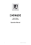
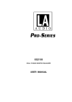
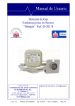
7610.530.10B
5/02
Refrigerated Compressed Air Dryers
Models DRD 25, 35, 50, 75, 100, 125, 150
Instruction Manual
For Sales or Service Call: 705-722-5747 Ext.1
Contents
GENERAL SAFETY INFORMATION ............................... 2
RECEIVING, MOVING, UNPACKING ............................. 2
1.0 INSTALLATION ...................................................... 3
2.0 OPERATION .......................................................... 5
3.0 MAINTENANCE .................................................... 6
SIZING ......................................................................... 6
ENGINEERING DATA .................................................... 7
ELECTRICAL SCHEMATICS ........................................... 8
DIMENSIONS / WEIGHTS ............................................. 9
TROUBLESHOOTING .................................................... 10
PARTS LIST .................................................................. 11
WARRANTY ................................................................. 12
For Sales or Service Call: 705-722-5747 Ext.1
SERVICE DEPARTMENT: (724) 746-1100
GENERAL SAFETY INFORMATION
RECEIVING, MOVING, AND UNPACKING
A. RECEIVING
1. PRESSURIZED DEVICES:
This equipment is a pressure containing device.
Do not exceed maximum operating pressure as
shown on equipment serial number tag.
Make sure equipment is depressurized before
working on or disassembling it for service.
This shipment has been thoroughly checked, packed
and inspected before leaving our plant.
It was received in good condition by the carrier and
was so acknowledged.
Check for Visible Loss or Damage.
If this shipment shows evidence of loss or damage at
time of delivery to you, insist that a notation of this
loss or damage be made on the delivery receipt by
the carrier’s agent.
B. UNPACKING
2. ELECTRICAL:
This equipment requires electricity to operate.
Install equipment in compliance with all
applicable electrical codes.
Standard equipment is supplied with electrical
enclosures not intended for installation in
hazardous environments.
Disconnect power supply to equipment when
performing any electrical service work.
Check for Concealed Loss or Damage.
When a shipment has beendelivered to you in
apparent good order, but concealed damage is
found uponunpacking, notify the carrier
immediately and insist on his agent inspecting the
shipment.
Concealed damage claims are not our responsibility
as our terms are F.O.B. point of shipment.
C. MOVING
In moving or transporting dryer, do not tip dryer
onto its side.
3. BREATHING AIR:
Air treated by this equipment may not be suitable
for breathing without further purification.
Refer to applicable standards and specifications for
the requirements for breathing quality air.
D. STORAGE
IMPORTANT - Do not store dryer in temperatures
above 130°F, 54.4°C.
For Sales or Service Call: 705-722-5747 Ext.1
2
1.2 Mounting
IMPORTANT:
READ PRIOR TO STARTING THIS EQUIPMENT
Mount on floor or shelf free from vibration.
1.0 Installation
1.1 Location
A. For typical placement in a compressed air system,
see drawing.
B. Air compressor intake–Locate air compressor so
that contaminants potentially harmful to the
dryer (e.g. ammonia) are not drawn into the air
system.
Aftercooler
Dryer
Oil Removal
Filter
Separator
Compressor
C. Clearances
Free air flow - Allow at least 12 inches (305 mm) on
the front and each side of the cabinet and 6 inches
(152 mm) at the back of the cabinet for free air flow.
Service - To facilitate maintenance leave 24 inches
(610 mm) of clearance in front of dryer.
D. Standard units are designed to operate in ambients
from 45 to 110°F (7 to 43°C).
E. Installations in altitudes above 4500 feet (1370 meters)
– Dryer is adjusted to operate in altitudes up to 4500
feet (1370 meters). If dryer is installed in an altitude
above this, and has not been preset at the factory for
this altitude, contact manufacturer’s Service Department.
NOTE: Outdoor installation–Standard units are designed
for indoor installation. Contact manufacturer if installing
outdoors.
Power On
Light
Temperature
Indicator
On/Off Switch
Air Inlet
Air Outlet
Separator
Condenser
Drain
Air Flow
Power Cord
Quick Release
Locks
* Screws used for shipping only.
Remove after installation.
For Sales or Service Call: 705-722-5747 Ext.1
3
1.3 Piping connections
1.4 Electrical connections
A. Air Inlet—Connect compressed air line from air
source to air inlet.
A. Dryer is designed to operate on the voltage, phase,
and frequency listed on the serial number tag.
B. Dryer is supplied with a cord and plug. Install in a
receptacle of proper voltage.
Air Inlet
Air Outlet
NOTE:
Refrigeration condensing unit is designed to run continuously and should NOT be wired to cycle on/off with the air
compressor.
NOTE:
Models 150 (115V only)—install plug in receptacle rated
for 20 amps.
WARNING: Refer to Serial Number Tag for maximum
working pressure. Do not exceed dryer’s Maximum
Working Pressure.
NOTE:
Install dryer in air system at highest pressure possible
(e.g. before pressure reducing valves).
NOTE:
Install dryer at coolest compressed air temperature
possible. Maximum inlet compressed air temperature:
120°F (49°C). If inlet air exceeds this temperature, precool
the air with an aftercooler.
1.5 Moisture separator
A. Separator has an internal drain which automatically
discharges collected condensate. It may be desirable
to pipe the condensate from the Automatic Drain
outlet to a suitable drain.
NOTE:
Discharge is at system pressure. Drain line should be
anchored.
B. Air Outlet—Connect air outlet to downstream
air lines.
C. By-pass piping—
If servicing the dryer without interrupting the
air supply is desired, piping should include
inlet and outlet valves and an air by-pass valve.
D. Water cooled models—cooling water inlet and
outlet
1. Connect cooling water supply to cooling water
inlet.
2. Connect cooling water return line to cooling
water outlet connection.
NOTE:
Condensate may contain oil. Comply with applicable laws
concerning proper disposal.
B. Separator has a knurled fitting with flexible drain
tubing attached. Be sure knurled fitting is tightened
by turning it counter-clockwise before operating
dryer.
NOTE:
Strainer and water regulating valve are supplied on water
cooled models.
TO CLOSE
TURN COUNTERCLOCKWISE
For Sales or Service Call: 705-722-5747 Ext.1
4
2.0 Operation
2.2 Start-up
2.1 Minimum/Maximum operating conditions
A. Maximum inlet air pressure: refer to dryer serial
number tag
Energize compressor by positioning the on/off switch in
the on (I) position. Compressor on light will illuminate.
2.3 Operating check points
B. Minimum inlet air pressure: 30 psig (2.1 kgf/cm2)
Check the following on a periodic basis:
C. Maximum inlet air temperature: 120°F (49°C)
A. Green power on light is illuminated.
D. Maximum ambient temperature:
Air-cooled models: 110°F (43°C)
Water-cooled models: 130°F (54°C)
B. Dewpoint indicator is in green area.
C. Condensate is discharging from drain.
E. Minimum ambient temperature: 45°F (7°C)
On/Off Switch
Power-On Light
Dewpoint Indicator (Green)
For Sales or Service Call: 705-722-5747 Ext.1
5
3.0 Maintenance
Sizing
3.1 Condenser coil—
Clean off accumulated dust and dirt monthly.
Determining dryer capacity at actual operating
conditions
3.2 Moisture separator—
Replace filter element when pressure drop across
dryer is excessive or annually.
To determine the maximum inlet flow capacity of a dryer
at various operating conditions, multiply the rated
capacity from Table 1 by the multipliers shown in Table 2.
Example: How many scfm can an air-cooled model 125
handle when compressed air to be dried is at 80 psig and
90°F; ambient air temperature is 80°F; and a 35°F dew
point temperature is desired?
Answer: 125 x 1.17 x 1.12 x 1.0 = 163.8 scfm.
3.3 Check separator daily to be sure automatic drain is
discharging.
3.4 Replace drain mechanism annually.
To facilitate service, maintenance kits are available.
TABLE 1
Rated capacity (scfm) and pressure drop @ 100 psig inlet
pressure, 100°F inlet temperature, and 100°F ambient
temperature
MODEL
Rated capacity of
air-cooled models (scfm)
Element o-ring
Bowl o-ring
60 Hz
50 Hz
25
35
50
75
100
125
150
25
21
35
29
50
42
75
63
100
84
125
105
150
125
Separator Element
Wave Spring
TABLE 2
Air capacity correction factors (Multipliers)
Drain Mechanism
INLET
PRESSURES
psig kgf/cm2
50
3.5
80
5.6
100
7.0
125
8.8
150
10.5
175
12.3
200
14.0
Tube
INLET COMPRESSED AIR CONDITIONS
INLET TEMPERATURES
90°F
100°F
110°F
80°F
27°C
32°C
38°C
43°C
1.35
1.05
0.84
0.69
1.50
1.17
0.95
0.79
1.55
1.23
1.00
0.82
1.63
1.31
1.07
0.91
1.70
1.37
1.13
0.95
1.75
1.42
1.18
0.99
1.80
1.47
1.22
1.03
120°F
49°C
0.56
0.66
0.70
0.74
0.80
0.84
0.89
Hose
Barb
COOLING MEDIUM*
AMBIENT
TEMPERATURE
MULTIPLIER
°F
°C
80
27
1.12
90
32
1.06
100
38
1.00
110
43
0.94
OUTLET DEWPOINT
DEW POINT
TEMPERATURE
MULTIPLIER
°F
°C
38
3
1.0
40
4
1.1
45
7
1.2
50
10
1.3
*Air-cooled models; water-cooled models use 1.15 multiplier if cooling water is
below 35°C, 95°F.
For Sales or Service Call: 705-722-5747 Ext.1
6
ENGINEERING DATA
Minimum – Maximum Operating Conditions
Min.-Max. Inlet Air Pressure (compressed air at inlet to dryer)
Max. Inlet Air Temp. (compressed air at inlet to dryer)
Min.-Max. Ambient Temperature
Refrigeration System Data
Compressor Type
Refrigeration Compressor Horsepower
BTU/HR – Refrigeration Only
@ 35°F Evaporator & 100°F Ambient
60 Hz / 50 Hz
Refrigerant Type
Refrigerant Charge
Suction Pressure Setting (controlled by hot gas by-pass valve)
Condenser Fan Switch Setting (in-out) (psig)
Air Flow Across Condenser (cfm)
60 Hz / 50 Hz
Condenser Cooling Water Requirements (gpm @ 85°F)
(water-cooled models only) (40 psig min. pressure)
Electrical
Nominal Voltages
Max.- Min. Voltage
Rated Load Amps
Locked Rotor Amps
Minimum Circuit Ampacity
Branch Circuit Fuse Size (amps)
Watts @ 35°F Evaporator & 100°F Ambient
Resistance (ohms)
Single phase
Start C/S
Run C/R
Overload
Nominal Voltages
Max.-Min. Voltage
Rated Load Amps
Locked Rotor Amps
Minimum Circuit Ampacity
Branch Circuit Fuse Size (amps)
Watts @ 35°F Evaporator & 100°F Ambient
Resistance (ohms)
Single phase
Start C/S
Run C/R
Overload
Nominal Voltages
Max.-Min. Voltage
Rated Load Amps
Locked Rotor Amps
Minimum Circuit Ampacity
Branch Circuit Fuse Size (amps)
Watts @ 35°F Evaporator & 100°F Ambient
Resistance (ohms)
Single phase
Start C/S
Run C/R
Overload
25
35
50
75
100 / 125
30 psig (2.1 kgf/cm2) - 250 psig (17.6 kgf/cm2)
120°F (49°C)
Air-cooled 45°F (7°C) - 110°F (43°C) Water-cooled 45°F (7°C) - 130°F (54°C)
1/6
Hermetic - Resistance Start, Induction Run - Non-Cycling
1/5
1/4
1/3
1/2
1010 / 842
R-134a
1380 / 1150
R-134a
31.5 psig
NA
105 / 98
31.5 psig
NA
235 / 196
NA
NA
127-104
3.4
18.0
4.0
15
280
-----
127-104
3.9
22.0
4.7
15
290
-----
253-187
1.8
8.5
2.2
15
280
-----
253-187
2.1
13.7
2.6
15
290
-----
264-198
1.6
8.7
2.0
15
223
-----
264-198
1.8
10.7
2.2
15
257
-----
2160 / 1800
2780 / 2317
R-134a
R-134a
See dryer serial number tag
31.5 psig
31.5 psig
NA
NA
275 / 229
220 / 183
NA
NA
115/1/60
127-104
127-104
5.9
7.4
28.0
35.0
7.3
9.1
15
15
465
600
--------Thermal & Current (Auto reset)
208-230/1/60
253-187
253-198
3.0
4.1
14.4
19.0
3.7
5.1
15
15
470
600
--------Thermal & Current (Auto reset)
220-240/1/50
264-198
264-198
2.6
3.5
14.5
15.2
3.2
4.4
15
15
395
507
--------Thermal & Current (Auto reset)
150
3/4
4430 / 3692
R-134a
6020 / 5017
R-134a
31.5 psig
NA
350 / 292
31.5 psig
110-70
530 / 440
NA
2.2 / 1.8
127-104
10.3
48.0
12.4
20
815
-----
127-104
14.7
66.3
18.3
25
1060
3.15
0.416
253-187
5.1
23.0
5.2
15
815
-----
253-198
8.3
33.5
10.5
15
1060
7.92
1.55
264-198
4.2
21.0
5.2
15
669
-----
264-198
7.6
53.0
9.9
15
930
10.49
1.8
For Sales or Service Call: 705-722-5747 Ext.1
7
ELECTRICAL SCHEMATIC
Models 25, 35 - 115V/60 Hz; 208-230V/60Hz; 220-240V/50 Hz
Model 50 - 115V/60 Hz; 220-240V/50 Hz
Model 75 - 115V/60 Hz
Model 150 - 230V/60 Hz
Model 50 - 208-230V/60Hz
Model 75 - 208-230V/60 Hz; 220-240V/50 Hz
Model 150 - 115V/60 Hz
Models 100, 125 - All Voltages
Legend
PBS - Push button switch
1LT - Power-on light
SR - Start Relay
CAP - Start Capacitor
MTR - Compressor
FM - Fan Motor
OL - Overload
FPS - Fan Pressure Switch (Only on 150 scfm)
CT - Contactor w/115v coil
SW - On/Off Switch
8
For Sales or Service Call: 705-722-5747 Ext.1
DIMENSIONS/WEIGHTS
Model
25
35
Dimensions
inches
50
75
100
A
B
C
D
E
F
G
H
I
Inlet/Outlet
Connections
Weights
lbs
17
22
17
1-13/16
4
15/16
1-7/8
3
1-3/16
17
22
17
1-13/16
4
15/16
1-7/8
3
1-3/16
19-15/16
24-7/16
17
1-15/16
5
15/16
1-7/8
3
1-3/16
21-9/16
28-11/16
20
1-15/16
5
15/16
1-7/8
3
1-3/16
21-9/16
28-11/16
20
1-15/16
5
15/16
1-7/8
3
1-3/16
3/4
3/4
1
1
1
1-1/2
1-1/2
105
118
156
180
198
229
230
D
125
C
E
150
26-15/16 26-15/16
30-1/8
30-1/8
23-3/4
23-3/4
2-3/16
2-3/16
5
5
15/16
15/16
1-7/8
1-7/8
3
3
1-3/16
1-3/16
B
I
A
F
G
G
Electrical Entry
Drain Outlet
H
H
Left Side View
Front View
Right Side View
For Sales or Service Call: 705-722-5747 Ext.1
9
TROUBLESHOOTING GUIDE
POSSIBLE CAUSE(S)
CORRECTIVE ACTION
1. Residual free moisture remaining
in downstream pipelines
2. Air by-pass system is open
3. Inlet and Outlet connections are
reversed
4. Temperatures surrounding air
lines downstream of dryer have
dropped below dryers dew point
rating
5. Excessive free moisture (bulk
liquid) at dryer inlet
6. Condensate not being automatically drained
Drain mechanism is clogged or
inoperative.
Drain line is restricted or frozen.
Electric drains–timer not set to
allow for sufficient condensate
removal
7. Dryer overloaded resulting in
elevated dew point.
Blow out system with dry air
SYMPTOM
A.
Water downstream of dryer
8. Refrigeration system not functioning properly resulting in
elevated dew point.
B.
C.
High pressure drop across
dryer
Dew point indicator in red
area
Check valve positions
Check for correct connection
Insulate or heat trace air lines exposed to
low ambients or dry air to lower dew point
Install separator ahead of dryer
Replace drain mechanism if inoperative
Open drain line
Electric drains–reset time so that all liquid
is discharged
Check inlet air temperature and pressure,
flow rate (compressor capacity) and
ambient air or water temperature.
See D below
1. Excessive air flow
2. Freezing of moisture in evaporator because of refrigeration
system improperly functioning.
3. Separator filter element clogged.
Check flow rate
See D below
1. Dryer overloaded resulting in high
air outlet temperature.
2. Refrigeration system not functioning properly resulting in high
air outlet temperature.
See A 7
Check power to unit
Close disconnect switch
Check for continuity
Have electrician check electrical
connections
Check min./max. temperature ranges
Clean condenser and check for free air
flow, if problem persists contact qualified
refrigeration repairman or manufacturer’s
service department.
Replace filter element.
See D below
D. Refrigeration system not
functioning properly
1.
Power on light off
a.
b.
c.
d.
2.
Refrigerant compressor
cycles on and off
a. High or low ambient conditions
b. Air-cooled models–Dirty, clogged
condenser fins, obstructed air
flow across condenser, or non
functioning fan motor or fan
control switch.
c. Water-cooled models–Cooling
water temperature too high, or
flow too low, faulty water regulating valve, clogged water strainer.
Power failure
Line disconnect switch open
Blown fuses, open breaker
Faulty wiring, loose terminals
Clean strainer, check water flow and
temperature, if problem persists contact
qualified refrigeration repairman or
manufacturer’s service department.
For Sales or Service Call: 705-722-5747 Ext.1
10
PARTS LIST
115/1/60
100/1/50
PARTS
DESCRIPTION
25
208-230/1/60
220-240/1/50
115/1/60
100/1/50
35
208-230/1/60
220-240/1/50
115/1/60
100/1/50
50
208-230/1/60
220-240/1/50
Condensing Unit (air-cooled)
Compressor Only
Overload
Start Relay
4130.120.7
4130.108.34
5925.570.2
5945.655.5
4130.120.8
4130.108.61
5925.578.24
5945.683.24
4130.120.9
4130.108.35
5925.570.3
5945.655.6
4130.121.8
4130.108.38
5925.578.1
5945.683.1
4130.121.9
4130.108.39
5925.578.2
5945.683.2
4130.121.10
4130.108.40
5925.578.3
5945.683.3
4130.122.10
4130.108.41
5925.578.4
5945.683.4
4130.122.11
4130.108.42
5925.578.5
5945.683.5
4130.122.15
4130.108.43
5925.578.6
5945.683.6
Start Capacitor
Fan Motor
Fan Blade
—
6105.239.1
4140.228.2
—
6105.237.4
4140.228.2
—
6105.237.4
4140.228.2
—
6105.238.27
4140.227.17
—
6105.238.28
4140.227.17
—
6105.238.28
4140.227.17
—
6105.238.29
4140.227.18
5910.103.23
6105.238.30
4140.227.18
—
6105.238.30
4140.227.18
Condenser (air-cooled)
4130.110.26
4130.110.26
4130.110.26
4130.111.18
4130.111.18
4130.111.18
4130.111.19
4130.111.19
4130.111.19
Dryer
Hot gas by-pass valve
By-pass valve strainer
Light assy., green
4130.165.14
9802-1
4130.701.8
6350.457.11
4130.165.14
9802-1
4130.701.8
6350.457.4
4130.165.14
9802-1
4130.701.8
6350.457.4
4130.165.14
9802-1
4130.701.8
6350.457.11
4130.165.14
9802-1
4130.701.8
6350.457.4
4130.165.14
9802-1
4130.701.8
6350.457.4
4130.165.14
9802-1
4130.701.8
6350.457.11
4130.165.14
9802-1
4130.701.8
6350.457.4
4130.165.14
9802-1
4130.701.8
6350.457.4
Dew Point Indicator
On/off switch
Maintenance Kit
Element
Drain
6685.283.1
6110.706.6
RDMK2C
DVE9-16
4460.151.10
6685.283.1
6110.706.6
RDMK2C
DVE9-16
4460.151.10
6685.283.1
6110.706.6
RDMK2C
DVE9-16
4460.151.10
6685.283.1
6110.706.6
RDMK2C
DVE9-16
4460.151.10
6685.283.1
6110.706.6
RDMK2C
DVE9-16
4460.151.10
6685.283.1
6110.706.6
RDMK2C
DVE9-16
4460.151.10
6685.283.1
6110.706.6
RDMK3C
DVE9-20
4460.151.10
6685.283.1
6110.706.6
RDMK3C
DVE9-20
4460.151.10
6685.283.1
6110.706.6
RDMK3C
DVE9-20
4460.151.10
115/1/60
100/1/50
PARTS
DESCRIPTION
75
208-230/1/60
220-240/1/50
115/1/60
100/1/50
100 & 125
208-230/1/60
220-240/1/50
115/1/60
100/1/50
150
208-230/1/60
220-240/1/50
Condensing Unit (air-cooled)
4130.122.12
4130.122.13
4130.122.14
4130.123.12
4130.123.13
4130.123.14
4130.134.31
4130.134.32
4130.134.33
Compressor Only
4130.108.44
4130.108.45
4130.108.46
4130.108.47
4130.108.48
4130.108.49
4130.108.50
4130.108.51
4130.108.52
Overload
5925.578.7
5925.578.8
5925.578.9
5925.578.10
5925.578.11
5925.578.12
5925.578.13
5925.578.14
5925.578.15
Start Relay
5945.683.7
5945.683.8
5945.683.9
5945.683.10
5945.683.11
5945.683.12
5945.683.13
5945.683.14
5945.683.15
Start Capacitor
Fan Motor
—
5910.103.26
5910.103.27
5910.103.28
5910.103.29
5910.103.29
5910.103.37
5910.103.38
5910.103.39
6105.238.31
6105.238.32
6105.238.32
6105.238.33
6105.238.34
6105.238.34
6105.238.35
6105.238.36
6105.238.36
Fan Blade
4140.227.19
4140.227.25
4140.227.25
4140.227.20
4140.227.20
4140.227.20
4140.227.21
4140.227.21
4140.227.21
Condenser (air-cooled)
4130.111.20
4130.111.20
4130.111.20
4130.111.21
4130.111.21
4130.111.21
4130.111.22
4130.111.22
4130.111.22
Dryer
4130.165.14
4130.165.14
4130.165.14
4130.165.14
4130.165.14
4130.165.14
4130.165.14
4130.165.14
4130.165.14
—
—
—
—
—
—
4130.138.13
4130.138.13
4130.138.13
Hot gas by-pass valve
9802-1
9802-1
9802-1
9802-1
9802-1
9802-1
9802-1
9802-1
9802-1
By-pass valve strainer
4130.701.8
4130.701.8
4130.701.8
4130.701.8
4130.701.8
4130.701.8
4130.701.8
4130.701.8
4130.701.8
Light assy., green
6350.457.25
6350.457.23
6350.457.23
6350.457.25
6350.457.23
6350.457.23
6350.457.25
6350.457.23
6350.457.23
Dew Point Indicator
6685.283.1
6685.283.1
6685.283.1
6685.283.1
6685.283.1
6685.283.1
6685.283.1
6685.283.1
6685.283.1
On/off switch
6110.706.6
6110.706.6
6110.706.6
6110.706.6
6110.706.6
6110.706.6
6110.706.6
6110.706.6
6110.706.6
Fan Pressure Switch
Contactor
Maintenance Kit
Element
Drain
—
—
—
—
—
—
5910.134.11
—
—
RDMK4C
RDMK4C
RDMK4C
*
*
*
RDMK5C
RDMK5C
RDMK5C
DVE9-24
DVE9-24
DVE9-24
**
**
**
DVE9-28
DVE9-28
DVE9-28
4460.151.10
4460.151.10
4460.151.10
4460.151.10
4460.151.10
4460.151.10
4460.151.10
4460.151.10
4460.151.10
* Model 100 - RDMK4C
Model 125 - RDMK5C
** Model 100 - DVE9-24
Model 125 - DVE9-28
For Sales or Service Call: 705-722-5747 Ext.1
11
Warranty
The manufacturer warrants the product manufactured by it, when properly installed, operated, applied and
maintained in accordance with procedures and recommendations outlined in the manufacturer’s instruction manuals,
to be free of defects in material and workmanship for a period of one (1) year from date of purchase at the retail level
by the end user, not to exceed eighteen (18) months from the date of manufacture, provided such defect is
discovered and brought to the manufacturers attention within the aforesaid warranty period.
The manufacturer will repair or replace any product or part determined to be defective by the manufacturer within
the warranty period, provided such defect occurred in normal service and not as the result of misapplication, misuse,
abuse, neglect, incorrect maintenance, accident, or normal wear. Normal maintenance items requiring routine
replacement are not warranted.
The warranty covers parts and labour for the warranty period. Repair or replacement shall be made at the sole option
of the manufacturer. Any service performed on the product by anyone other than the manufacturer must first be
authorized by the manufacturer. Unauthorized service voids the warranty and any resulting charge or subsequent
claim will not be paid.
Products repaired or replaced under warranty shall be warranted for the unexpired portion of the warranty applying to
the original product, based on the original date of purchase and/or date of manufacture, as outlined above.
There is no other expressed warranty. Implied warranties including those of merchantability and fitness for a particular
purpose are limited to one (1) year from date of purchase to the extent permitted by law and any and all implied
warranties are excluded. This is the exclusive remedy. Liability for consequential damages under any and all warranties
are excluded to the extent exclusion is permitted by law.
This warranty gives you specific legal rights, and you may also have other rights within your jurisdiction.
This warranty does not cover:
1. Merchandise that has become inoperative because of ordinary wear, misuse, negligence, accident, or improper
and unauthorized repair or alteration.
2. Costs occasioned by the removal, replacement, or repair of merchandise (other than by Devair) without
previous written authorization.
3. Expenses incurred in travel or lodging beyond a 40 kilometer (25 mile) distance from the nearest Devair
Authorized Service Centre, unless approved by Devair in advance.
4. Products, parts, materials, components, or accessories manufactured by others or supplied in connection with
the sale of the manufacturers products.
5. Repair and transportation costs of merchandise determined not to be defective under the terms and
conditions of this warranty.
All decisions by Devair Inc. with regard to this policy shall be final. Devair will not be responsible for any claimed
defective materials returned other than in accordance with this statement of policy or without our prior authorization.
For SERVICE
Sales orDEPARTMENT:
Service Call:(724)
705-722-5747
Ext.1
746-1100
Devair Inc.
P.O. Box 5800 Barrie, Ontario L4M 6K3
Tel: (705) 728-5657