1
Electrical installation
Operating Instructions
Chapter 5
ICR890
5
Electrical installation
5.1
Note
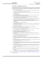
Overview of installation sequence
Complete installation of all the components is a prerequisite for electrical installation
(see Chapter 4 Installation, page 45).
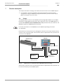
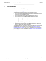
The following list provides an overview of a typical installation sequence:
•
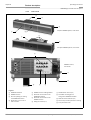
Connecting the power supply of the ICI890 Illumination and the illumination control line
to the camera (system-internal connections)
•
Connecting the ICD890 Camera to the external power supply (24 V DC)
•
Connecting the host processor (RS 232, RS 422/485, Ethernet or CAN)
•
Connecting the reading pulse sensor(s)
•
Connecting the MLG Light Grid (RS 485) or the VMS4xx/5xx (CAN)
•
Connecting the incremental encoder
•
Connecting a PC/laptop temporarily for startup/configuration (RS 232 or Ethernet)
•
Optional: Wiring the switching outputs for system status indication
•
Optional: Connecting the special PC with 2 GBit Ethernet interfaces and software
(driver) for real-time image transfer/presentation
The actual installation work which has to be carried out depends on the respective system
configuration with which the ICR890 System is operated (see Chapter 5.2 Electrical
installation preparation, page 54). Once electrical installation has been completed, the
system is started up, adjusted and configured (see Chapter 6.1 Overview of the startup
procedure, page 79).
8011325/0000/2006-10-24
© SICK AG · Division Auto Ident · Germany · All rights reserved
53