1
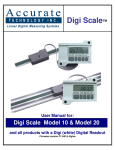
Digi Fence User Manual for: Digi Fence (All Models) Readout Firmware version d 2.000 & Higher ® Accurate Technology Digi Fence Page 2 of 16 Warranty Accurate Technology, Inc., warrants this product against defective parts and workmanship for 1 year commencing from the date of original purchase. Upon notification of a defect, Accurate Technology, Inc., shall have the option to repair or replace any defective part. Such services shall be the customer's sole and exclusive remedy. Expenses incidental to repair, maintenance, or replacement under warranty, including those for labor and material, shall be borne by Accurate Technology, Inc. (Including freight or transportation charges during the first 30 days). Except as expressly provided in this warranty, Accurate Technology, Inc., does not make any warranties with respect to the product, either expressed or implied, including implied warranties of merchantability or fitness for a particular purpose, except as expressly provided in this agreement. Accurate Technology, Inc., shall not be liable for any special, incidental, or consequential damages or for loss, damage or expense directly or indirectly arising from the customer's use of or inability to use the equipment either separately or in combination with other equipment, or for personal injury or loss or destruction of other property, or from any other cause. To request repair work (either warranty qualified parts or not), contact Accurate Technology, Inc. directly by phone, fax, or e-mail. A Returned Merchandise Authorization (RMA) number is required before returning a product for repair. Accurate Technology, Inc. +1 828.654.7920 800.233.0580 828.654.8824 (F) www.digi-kit.com [email protected] SAFETY WARNING Before installing Digi Fence on any machinery: Turn off the machine and disconnect the power. SAFETY WARNING P/N 800-1100-001 Rev. F Copyright Accurate Technology 2008 Accurate Technology Digi Fence Page 3 of 16 Table of Contents SECTION 1 GENERAL INFORMATION ......................................................................... 5 Introduction ............................................................................................................... 5 What This Manual Includes ....................................................................................... 5 Digi Fence Specifications .......................................................................................... 5 SECTION 2 INSTALLATION ....................................................................................... 6 Calibration................................................................................................................. 7 Maintenance ............................................................................................................. 7 SECTION 3 OPERATION .......................................................................................... 8 Readout Keys............................................................................................................ 8 Timing..................................................................................................................... 8 On/Off..................................................................................................................... 8 Mode ...................................................................................................................... 8 +, 0, and – Keys...................................................................................................... 9 Display Resolution................................................................................................... 10 Incremental Measurements ..................................................................................... 10 Lock Mode .............................................................................................................. 10 Reverse Scaling ...................................................................................................... 10 Changing the Batteries............................................................................................ 11 Jumpers.................................................................................................................. 12 Programming .......................................................................................................... 13 Programming Parameters ....................................................................................... 14 Frequently Asked Questions ................................................................................... 15 Accurate Technology Digi Fence Page 4 of 16 SECTION 1 GENERAL INFORMATION Introduction This is a custom engineered system that adds a digital readout to your existing commercial style Table Saw fence. This kit is supplied with an Digi-Scale measuring system, and all the components needed for a quick and easy retrofit to your existing fence. The readout has easy-to-use front panel keys for calibration, incremental measurements, and changing of measurement units. User selectable resolution will display fractions in 16ths, 32nds, or 64ths; inches as .01 or .001, and millimeters as .1 or .01. The system is powered by two AA alkaline batteries. It is immune to dirt, sawdust or other non-conductive contaminants making it the ideal choice for shops and other dusty environments. What This Manual Includes This manual includes information for the following Digi Fence Systems: Biesemeyer & General SawStop & Steel City Delta Unifence XACTA II / Powermatic XACTA II / HTC Safety Speed Cut QuickStop Felder K700 Series Part Number: 903-1000-001 Part Number: 903-1007-001 Part Number: 903-1004-001 Part Number: 903-1001-001 Part Number: 903-1013-001 Part Number: 903-7001-001 Part Number: 903-7002-001 Digi Fence Specifications Measuring Range Accuracy: Resolution Repeatability: Readout Range: Operating Temp: Max. Slew Rate: Encoder: Dimensions: Warranty: 60 inches + .01inch .1in/.1mm. or 01in/.1mm or .001in/.01mm or 1/16, 1/32, 1/64 .01inch or .1mm + 999.999 in; + 399 63/64 in; + 9999.99 mm 32 to 120°F 15 inches/sec. (400 mm/sec.) 24 inch six-conductor cable terminated by RJ11 connector. Available at on request. One year from date of purchase. Accurate Technology Digi Fence Page 5 of 16 SECTION 2 INSTALLATION Digi Fence is designed so that the aluminum Scale can be mounted on the saw fence rail and the Encoder can be attached to the moving part of the fence. A guide clip connects the Encoder to the fence so the two move together. Figure 1 shows a typical installation. Bracket Guide Clip Encoder Scale Cable Underside View NOTE: Follow the Installation Instructions you received with your kit for proper installation on your fence model. Accurate Technology Digi Fence Page 6 of 16 Calibration There are two ways to set a zero reference (calibration). Quick Method: Move the fence until it just touches the blade and depress the Zero key on the front of the digital readout. Best Method: Cut a small piece of material. Measure the size with a caliper, and use the + and - keys on the front of the readout to set in the correct reading. When the correct reading is set, lock the Readout if desired. This prevents accidentally re-zeroing of the readout. See Section 3 for more information about how to lock the readout. Maintenance The Digital Readout should be cleaned periodically with compressed air to remove any dust on the lens and keys. All fasteners should occasionally be checked for tightness. Do not use any liquid lubricants on the scale assembly, as this may impede the Encoder's ability to operate properly and attract other contaminants to the scale. Accurate Technology Digi Fence Page 7 of 16 SECTION 3 OPERATION Readout Keys Timing The keys pictured above have multiple functions. Timing, that is how long a key is depressed, and the combination of the keys pressed, is important. This manual uses the term ‘”momentarily” to describe a key press of typically less than 1 second. Whereas “press and hold” is used imply a key press of typically longer than 1.5 seconds. As an example; when using a PC keyboard to type a capital letter you would “press and hold” the SHIFT key and “momentarily” depress the LETTER key. In addition, keep in mind the key’s “function” is executed on the key RELEASE, not the key DEPRESS. This is important since some keys execute different functions based on how long they are depressed. These key operations, once tried, quickly become intuitive. On/Off Momentarily pressing the ON/OFF key will cause the Readout to turn on or off. The Firmware Version is displayed on power-up when ON/OFF key is pressed. While on, if no key presses or positional changes occur within 15 minutes, the Digital Readout will automatically turn itself off to conserve battery life. While off, if a position change is detected (.05mm or .002in) or the ON/OFF button is pressed, the Readout will automatically turn itself on with no loss of measurement information. Mode The Digital Readout can display measurement information in decimal inches, fractions, or millimeters. To change the current display mode, momentarily press the MODE key. With each key press the Readout will cycle through decimal inches, fractional inches and millimeters. When the Readout is in 1/16 or 1/32 inch fraction mode, a series of “bars” in the upper right corner of the LCD each represent an additional 1/64th of an inch measurement. ie. When in 1/16 inch mode and three bars are showing, the measurement displayed is rounded down to closest 1/16 inch and each illuminated bar indicates an additional 1/64 of an inch (“heavy”) measurement. For better resolution switch to 1/32 or 1/64 fraction mode. For the best resolution switch to a decimal mode. (Inch or mm). Accurate Technology Digi Fence Page 8 of 16 When the measurement is greater than 99 63/64 inches, a +100 and/or +200 will illuminate in the upper right portion of the display to indicate this amount must be added to the displayed reading. ie: If the measurement is 151 39/64 inches, 51 39/64 and +100 will be illuminated on the display. See photo below. +, 0, and – Keys The + (plus), 0 (zero) and – (minus) keys are used to change the currently displayed position to a different value. The 0 key forces the unit to display 0. Momentarily depressing the + key increments the current position by one unit of measurement. Momentarily depressing the – key decrements the current position by one unit. Pressing and holding the + or – keys will cause the displayed position to change continuously. Holding down the key will cause the amount of change to speed up. This allows for quick adjustments over a range of large values. NOTE: While the 0 (zero) key can be used to simply “zero” the currently displayed value, it can also be programmed to force the display to a preset value. This can be zero, or any other displayable value. See Programming Parameter Pr1 Accurate Technology Digi Fence Page 9 of 16 Display Resolution The Digital Readout can be configured to display measurements with different resolution. In Normal display mode the resolution is: .01in or .01mm. In Higher display mode the resolution is: .001in or .01mm In Lower display mode the resolution is: .1in or .1mm. Fractions remain the same for all settings: 1/16, 1/32 & 1/64 See Programming Parameter Pr4 Incremental Measurements To make Incremental measurements, press and hold MODE key for approximately 3 seconds. This switches the Readout to INCremental mode (as shown in the upper left corner of the LCD). You can now press the ZERO, + or – keys if desired. Any measurement taken will be an incremental measurement and you will not lose your original ABSolute position. While in the Incremental measurement mode, the Readout can be re-zeroed for repeated incremental measurements by pressing the ZERO key. To recall + and - offsets in Incremental measurement mode, simply press the MODE key for repeated incremental measurements. Measurement units (in, mm, fraction) changes are not allowed while in INC mode. To return to the ABS measuring mode, press the MODE key for 3 seconds. Lock Mode The user can “lock-out” the position offset adjustment functions (+, -, 0 keys) to prevent accidental changes of the current displayed position. To activate the lock mode, press and hold the ON/OFF key and then momentarily press the MODE key. The word LOCK will appear in the upper left corner of the LCD, and the +, - and 0 keys will not change the displayed position. For a more permanent keypad lock solution, See Programming Parameter Pr3 Reverse Scaling If you set a zero point on ProScale, moving the scale in one direction will produce positive readings. Moving the scale past zero in the opposite direction will produce negative readings. Reverse scaling means changing the orientation of the Encoder so that positive readings become negative and negative readings become positive. There are two methods to reverse readings: 1. Slide the Encoder off the scale and re-install the Encoder in the opposite direction, being careful not to damage the ground fingers inside the Encoder. 2. Change Programming Parameter Pr2 Accurate Technology Digi Fence Page 10 of 16 Changing the Batteries A “BAT” indicator will appear in the upper left corner of the LCD display when new batteries are needed. Remove the screws in the upper right and lower left corners. Pull the cover off. Remove the old batteries. Reinstall new AA Alkaline batteries, noting the proper orientation. Replace the cover and tighten the screws. CAUTION: DO NOT BEND BATTERY CLIPS! THESE CLIPS ARE DESIGNED TO BE LOOSE WHEN THE CASE IS OPEN AND WILL COMPRESS AND SECURE THE BATTERIES IN PLACE WHEN THE CASE HALVES ARE SCREWED TOGETHER. Accurate Technology Digi Fence Page 11 of 16 Jumpers User configurable jumpers consist of three pins and a ‘shorting block’. The center of these pins is ‘Common’. One end pin is labeled ‘A’ and the other end pin is labeled ‘B’. JP1 JP2 JP1 FACTORY USE ONLY JP2 Programming Lockout When jumper is in Position A, Front Panel Programming is ENABLED When jumper is in Position B, Front Panel Programming is DISABLED Accurate Technology Digi Fence Page 12 of 16 Programming Several functions of this Digital Readout are user programmable. The following describes how to change the factory defaults to customize your Digital Readout. To enter Programming Mode: 1. 2. 3. 4. Press and hold the MODE key then momentarily press the 0 key. The LCD will briefly display: pg on (Programming On), then Pr 1, (indicating Programming Parameter #1). Release the MODE key. The value stored for Pr1 is displayed. Press & Hold Momentarily press Once in the Programming Mode: Moving up parameter list - Momentarily press the MODE key to advance through the Programming Parameter list, first displaying the Programming Parameter number then the currently programmed value. Moving down parameter list - Press and hold the ON/OFF key and momentarily press the MODE key to move backward through the Programming Parameter list. Increase parameter value - Momentarily press the PLUS (+) key while displaying a Programming Parameter Value to increase the parameter setting. Decrease parameter value - Momentarily press the MINUS (-) key while displaying a Programming Parameter Value to decrease the parameter setting. Reset parameter value to default setting - Momentarily press the ZERO (0) key while displaying a Programming Parameter Value to reset it to the factory default value. Exit programming mode - Press and hold the MODE key. Momentarily depress the 0 key. The LCD will briefly display: pg oFF (Programming Off), and will then return to normal operation. NOTE: The system will automatically exit programming mode after 60 seconds of no key activity. Accurate Technology Digi Fence Page 13 of 16 Programming Parameters Programming Parameters are listed below. Values in [ ] are the available range of values that can be programmed for that parameter. Factory defaults are shown in Bold Red. Pr 1: 0 Key Value [0 to + 999.999in] or [0 to +9999.99mm] The programmed value that will be recalled whenever the 0 (zero) key is pressed during normal operation. Default = 0 Pr 2: Reverse Scaling [0 or 1] This parameter controls the sign of travel (positive vs negative) when the measuring system is moved. Default = 0 Pr 3: Key Lockout [0 or 1] This parameter controls the operation of the +, - and 0 keys. If enabled (set to 1), these keys will not function and the word LOCK will appear on the display. This prevents accidental changes when depressing these keys during normal operation. Default = 0 Pr 4: Display Resolution [1, 2 or 3] This parameter sets the number of places to the right of the decimal point on the display when the Digi Readout is in a decimal mode (in or mm). A value of 1 will display x.x. A value of 2 will display x.xx A value of 3 will display x.xxx Default = 2 NOTES: Decimal inches have a maximum of 3 places. Millimeters have a maximum of 2 places (even if parameter is set to 3.) This setting has no effect when displaying fractions. Accurate Technology Digi Fence Page 14 of 16 Frequently Asked Questions What F/W (Firmware) version do I have? The display will show d 2.xxx on power up. This is the firmware version of your Readout. What does “no Enc” mean? If the Encoder cable is unplugged from the Readout, no Enc will appear on the display. To clear: Be sure the Encoder is on the scale and plugged into the readout The keys don’t seem to do what they are supposed to do. Timing, that is how long a key is depressed, and the combination of the keys pressed is important. This manual uses the term ‘”momentarily” to describe a key press of typically less than 1 second. Whereas “press and hold” is used imply a key press of typically longer than 1.5 seconds. As an example; when using a PC keyboard to type a capital letter you would “press and hold” the SHIFT key and “momentarily” depress the LETTER key. In addition, keep in mind the key’s “function” is executed on the key RELEASE, not the key DEPRESS. This is important since some keys execute different functions based on how long they are depressed. The battery clips seem to be very loose. Is this normal? Yes. DO NOT attempt to bend these clips or wedge anything between them and the case. These clips are designed to expand when the two case halves are screwed together. The readings are “backwards”? You can change the “scaling” direction of the system by: 1. Reversing the orientation of the Encoder on the Scale. 2. Changing the value of Programming Parameter Pr 2. Accurate Technology Digi Fence Page 15 of 16 Thank you for choosing an Accurate Technology Product Please register your system at: http://www.proscale.com/registration.htm Accurate Technology, Inc. 270 Rutledge Rd. Unit E Fletcher, NC 28732 USA 800 233-0580 • 828-654-7920 Fax 828-654-8824 www.digi-kit.com [email protected] This manual is available online at www.digi-kit.com P/N 800-1100-001 Rev. F Copyright Accurate Technology 2008 Accurate Technology Digi Fence Page 16 of 16