1
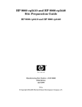
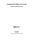
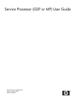
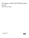
Operations Guide
HP 9000 rp3410 and HP 9000 rp3440
Manufacturing Part Number: A7137-96003
Second Edition
April 2005
U.S.A.
© Copyright 2004-2005 Hewlett-Packard Development Company, L.P..
Legal Notices
Copyright Notices. © Copyright 2004-2005 Hewlett-Packard Development Company, L.P.
The information contained herein is subject to change without notice.
The only warranties for HP products and services are set forth in the express warranty statements
accompanying such products and services. Nothing herein should be construed as constituting an additional
warranty. HP shall not be liable for technical or editorial errors or omissions contained herein.
2
Contents
1. Controls, Ports, and Indicators
Control Panel . . . . . . . . . . . . . . . . . . . . . . . . . . . . . . . . . . . . . . . . . . . . . . . . . . . . . . . . . . . . . . . . . . . . . . .
Additional Controls and Indicators. . . . . . . . . . . . . . . . . . . . . . . . . . . . . . . . . . . . . . . . . . . . . . . . . . . . . .
Hot-Plug Disk Drive Indicators . . . . . . . . . . . . . . . . . . . . . . . . . . . . . . . . . . . . . . . . . . . . . . . . . . . . . . .
Optional Removable Media Drive . . . . . . . . . . . . . . . . . . . . . . . . . . . . . . . . . . . . . . . . . . . . . . . . . . . . .
Rear Panel . . . . . . . . . . . . . . . . . . . . . . . . . . . . . . . . . . . . . . . . . . . . . . . . . . . . . . . . . . . . . . . . . . . . . . . . .
10/100/1000 Base-T Ethernet LAN Connector . . . . . . . . . . . . . . . . . . . . . . . . . . . . . . . . . . . . . . . . . . .
iLO Manageability Card LAN LEDs . . . . . . . . . . . . . . . . . . . . . . . . . . . . . . . . . . . . . . . . . . . . . . . . . . .
11
14
14
15
16
17
18
2. External Connectors
Connector Pinouts . . . . . . . . . . . . . . . . . . . . . . . . . . . . . . . . . . . . . . . . . . . . . . . . . . . . . . . . . . . . . . . . . . .
Universal Serial Bus (USB 2.0) Ports . . . . . . . . . . . . . . . . . . . . . . . . . . . . . . . . . . . . . . . . . . . . . . . . . . . .
SCSI Port, Ultra 3, 68-Pin . . . . . . . . . . . . . . . . . . . . . . . . . . . . . . . . . . . . . . . . . . . . . . . . . . . . . . . . . . . . .
10/100/1000 LAN Connector . . . . . . . . . . . . . . . . . . . . . . . . . . . . . . . . . . . . . . . . . . . . . . . . . . . . . . . . . . .
iLO Manageability Card LAN . . . . . . . . . . . . . . . . . . . . . . . . . . . . . . . . . . . . . . . . . . . . . . . . . . . . . . . .
19
20
21
23
24
3. Utilities
Boot Console Handler (BCH). . . . . . . . . . . . . . . . . . . . . . . . . . . . . . . . . . . . . . . . . . . . . . . . . . . . . . . . . . .
BCH Commands . . . . . . . . . . . . . . . . . . . . . . . . . . . . . . . . . . . . . . . . . . . . . . . . . . . . . . . . . . . . . . . . . . .
Management Processor (MP). . . . . . . . . . . . . . . . . . . . . . . . . . . . . . . . . . . . . . . . . . . . . . . . . . . . . . . . . . .
Configuring the MP LAN Port IP Address . . . . . . . . . . . . . . . . . . . . . . . . . . . . . . . . . . . . . . . . . . . . . .
Accessing the Management Processor . . . . . . . . . . . . . . . . . . . . . . . . . . . . . . . . . . . . . . . . . . . . . . . . . .
Configuring the Management Processor LAN Information . . . . . . . . . . . . . . . . . . . . . . . . . . . . . . . . .
MP Command Reference . . . . . . . . . . . . . . . . . . . . . . . . . . . . . . . . . . . . . . . . . . . . . . . . . . . . . . . . . . . .
25
25
31
32
33
35
38
4. Troubleshooting
Information to Collect Before You Contact Support. . . . . . . . . . . . . . . . . . . . . . . . . . . . . . . . . . . . . . . . .
Troubleshooting Methodology . . . . . . . . . . . . . . . . . . . . . . . . . . . . . . . . . . . . . . . . . . . . . . . . . . . . . . . . . .
Using the Front Panel Power Button. . . . . . . . . . . . . . . . . . . . . . . . . . . . . . . . . . . . . . . . . . . . . . . . . . .
Operating System Will Boot . . . . . . . . . . . . . . . . . . . . . . . . . . . . . . . . . . . . . . . . . . . . . . . . . . . . . . . . . . .
Support Tools Manager . . . . . . . . . . . . . . . . . . . . . . . . . . . . . . . . . . . . . . . . . . . . . . . . . . . . . . . . . . . . .
Event Monitoring Service. . . . . . . . . . . . . . . . . . . . . . . . . . . . . . . . . . . . . . . . . . . . . . . . . . . . . . . . . . . .
Management Processor. . . . . . . . . . . . . . . . . . . . . . . . . . . . . . . . . . . . . . . . . . . . . . . . . . . . . . . . . . . . . .
Operating System Will Not Boot . . . . . . . . . . . . . . . . . . . . . . . . . . . . . . . . . . . . . . . . . . . . . . . . . . . . . . . .
Offline Diagnostic Environment (ODE). . . . . . . . . . . . . . . . . . . . . . . . . . . . . . . . . . . . . . . . . . . . . . . . .
Identifying and Diagnosing Hardware Problems. . . . . . . . . . . . . . . . . . . . . . . . . . . . . . . . . . . . . . . . . . .
Troubleshooting Using LEDs . . . . . . . . . . . . . . . . . . . . . . . . . . . . . . . . . . . . . . . . . . . . . . . . . . . . . . . . .
LAN LEDs . . . . . . . . . . . . . . . . . . . . . . . . . . . . . . . . . . . . . . . . . . . . . . . . . . . . . . . . . . . . . . . . . . . . . . . . .
System Board Diagnostic LEDs . . . . . . . . . . . . . . . . . . . . . . . . . . . . . . . . . . . . . . . . . . . . . . . . . . . . . . . .
Cleaning Procedures . . . . . . . . . . . . . . . . . . . . . . . . . . . . . . . . . . . . . . . . . . . . . . . . . . . . . . . . . . . . . . . . .
Where to Get Help . . . . . . . . . . . . . . . . . . . . . . . . . . . . . . . . . . . . . . . . . . . . . . . . . . . . . . . . . . . . . . . . . . .
Information to Collect Before you Contact Support . . . . . . . . . . . . . . . . . . . . . . . . . . . . . . . . . . . . . . .
Online Support . . . . . . . . . . . . . . . . . . . . . . . . . . . . . . . . . . . . . . . . . . . . . . . . . . . . . . . . . . . . . . . . . . . .
Phone Support. . . . . . . . . . . . . . . . . . . . . . . . . . . . . . . . . . . . . . . . . . . . . . . . . . . . . . . . . . . . . . . . . . . . .
41
41
42
44
44
44
45
48
48
49
49
51
52
54
55
55
55
56
5. Specifications
3
Contents
Introduction . . . . . . . . . . . . . . . . . . . . . . . . . . . . . . . . . . . . . . . . . . . . . . . . . . . . . . . . . . . . . . . . . . . . . . . .
Hardware Specifications . . . . . . . . . . . . . . . . . . . . . . . . . . . . . . . . . . . . . . . . . . . . . . . . . . . . . . . . . . . . . .
Server Dimensions and Weights . . . . . . . . . . . . . . . . . . . . . . . . . . . . . . . . . . . . . . . . . . . . . . . . . . . . . . . .
Component Dimensions . . . . . . . . . . . . . . . . . . . . . . . . . . . . . . . . . . . . . . . . . . . . . . . . . . . . . . . . . . . . .
57
57
59
59
Index . . . . . . . . . . . . . . . . . . . . . . . . . . . . . . . . . . . . . . . . . . . . . . . . . . . . . . . . . . . . . . . . . . . . . . . 61
4
Figures
Figure 1-1. Front View . . . . . . . . . . . . . . . . . . . . . . . . . . . . . . . . . . . . . . . . . . . . . . . . . . . . . . . . . . . . .
Figure 1-2. Control Panel. . . . . . . . . . . . . . . . . . . . . . . . . . . . . . . . . . . . . . . . . . . . . . . . . . . . . . . . . . .
Figure 1-3. Hot-Plug Disk Drive LED Indicators. . . . . . . . . . . . . . . . . . . . . . . . . . . . . . . . . . . . . . . .
Figure 1-4. DVD–ROM. . . . . . . . . . . . . . . . . . . . . . . . . . . . . . . . . . . . . . . . . . . . . . . . . . . . . . . . . . . . .
Figure 1-5. Rear View . . . . . . . . . . . . . . . . . . . . . . . . . . . . . . . . . . . . . . . . . . . . . . . . . . . . . . . . . . . . .
Figure 1-6. 10/100/1000 Base-T Ethernet LAN Connector LEDs . . . . . . . . . . . . . . . . . . . . . . . . . . .
Figure 1-7. iLO Manageability Card LAN LEDs . . . . . . . . . . . . . . . . . . . . . . . . . . . . . . . . . . . . . . . .
Figure 2-1. Rear View of Server . . . . . . . . . . . . . . . . . . . . . . . . . . . . . . . . . . . . . . . . . . . . . . . . . . . . .
Figure 2-2. Dual USB Port Connector. . . . . . . . . . . . . . . . . . . . . . . . . . . . . . . . . . . . . . . . . . . . . . . . .
Figure 2-3. Single USB Port . . . . . . . . . . . . . . . . . . . . . . . . . . . . . . . . . . . . . . . . . . . . . . . . . . . . . . . .
Figure 2-4. SCSI Port, Ultra 3, 68-Pin . . . . . . . . . . . . . . . . . . . . . . . . . . . . . . . . . . . . . . . . . . . . . . . .
Figure 2-5. 10/100/1000 LAN Connector. . . . . . . . . . . . . . . . . . . . . . . . . . . . . . . . . . . . . . . . . . . . . . .
Figure 2-6. iLO Manageability Card LAN Connector . . . . . . . . . . . . . . . . . . . . . . . . . . . . . . . . . . . .
Figure 4-1. Control Panel LEDs . . . . . . . . . . . . . . . . . . . . . . . . . . . . . . . . . . . . . . . . . . . . . . . . . . . . .
Figure 4-2. Location of the STBY and BMC LEDs. . . . . . . . . . . . . . . . . . . . . . . . . . . . . . . . . . . . . . .
11
11
14
15
16
17
18
19
20
20
21
23
24
49
52
5
Figures
6
Preface
This preface contains the following sections:
•
Intended Audience
•
What’s New?
•
Notational Conventions
•
Reader Comments and Feedback
•
Related Information
•
Printing History
Intended Audience
This document is intended to provide technical product and support information for authorized service
providers, customer system administrators, and HP support personnel.
What’s New?
•
The layout of this document was changed to improve usability.
Notational Conventions
The following notational conventions are used in this publication.
WARNING
A warning lists requirements that you must meet to avoid personal injury.
CAUTION
A caution provides information required to avoid losing data or avoid losing system
functionality.
NOTE
A note highlights useful information such as restrictions, recommendations, or important
details about HP product features.
•
Commands and options are represented using this font.
•
Text that you type exactly as shown is represented using this font.
•
Text to be replaced with text that you supply is represented using this font.
Example:
“Enter the ls -l filename command” means you must replace filename with your own text.
•
Keyboard keys and graphical interface items (such as buttons, tabs, and menu items) are represented using this
font.
Examples:
The Control key, the OK button, the General tab, the Options menu.
•
Menu —> Submenu represents a menu selection you can perform.
7
Example:
“Select the Partition —> Create Partition action” means you must select the Create Partition menu item from
the Partition menu.
•
Example screen output is represented using this font.
Reader Comments and Feedback
HP welcomes your feedback on this publication. Please address your comments to
[email protected] and note that you will not receive an immediate reply. All comments are
appreciated.
Related Information
You can find other information on HP server hardware management, Microsoft® Windows®, and diagnostic
support tools in the following publications.
Web Site for HP Technical Documentation:
http://docs.hp.com
The main Web site for HP technical documentation is http://docs.hp.com, which has complete information
available for free.
Server Hardware Information:
http://docs.hp.com/hpux/hw/
The http://docs.hp.com/hpux/hw/ Web site is the systems hardware portion of the docs.hp.com and
provides HP nPartition server hardware management details, including site preparation, installation, and
more.
Windows Operating System Information
You can find information about administration of the Microsoft® Windows® operating system at the
following Web sites, among others:
•
http://docs.hp.com/windows_nt/
•
http://www.microsoft.com/technet/
Diagnostics and Event Monitoring: Hardware Support Tools
Complete information about HP’s hardware support tools, including online and offline diagnostics and event
monitoring tools, is at the http://docs.hp.com/hpux/diag/ Web site. This site has manuals, tutorials,
FAQs, and other reference material.
Web Site for HP Technical Support:
http://us-support2.external.hp.com
HP’s IT resource center Web site at http://us-support2.external.hp.com/ provides comprehensive
support information for IT professionals on a wide variety of topics, including software, hardware, and
networking.
Books about HP-UX Published by Prentice Hall
The http://www.hp.com/hpbooks/ Web site lists the HP books that Prentice Hall currently publishes, such
as HP-UX books including:
8
•
HP-UX 11i System Administration Handbook
http://www.hp.com/hpbooks/prentice/ptr_0130600814.html
•
HP-UX Virtual Partitions
http://www.hp.com/hpbooks/prentice/ptr_0130352128.html
HP Books are available worldwide through bookstores, online booksellers, and office and computer stores.
Printing History
The Printing History below identifies the edition dates of this manual. Updates are made to this publication
on an unscheduled, as needed, basis. The updates will consist of a complete replacement manual and
pertinent on-line or CD-ROM documentation.
Second Edition
........................................................
July 2004
Third Edition
........................................................
April 2005
9
10
1 Controls, Ports, and Indicators
This chapter describes the controls, ports, and indicators found on the front panel and rear panel locations of
the HP 9000 rp3410 or HP 9000 rp3440 server. The HP 9000 rp3410 and HP 9000 rp3440 servers are
designed to be rack or pedestal mounted.
Control Panel
The control panel of the HP 9000 rp3410 and HP 9000 rp3440 servers provide the controls and indicators
commonly used for operation.
Figure 1-1
Front View
Control Panel
DVD Drive
Drive 3
Drive 2
Drive 1
System Product
Label (pull-out)
Figure 1-2
Control Panel
Locator Button and LED
Diagnostics LEDs
(Disabled)
1
Chapter 1
2
3
4
LAN
LED
Power Button
System
LED
Power On/Off LED
LAN System
11
Controls, Ports, and Indicators
Control Panel
Table 1-1
Name
Control Panel LEDs and Switches
Function
Power on/off
LED
The green on/off LED is illuminated when the power is on.
Power button
Controls the power supply (turns system power on/off) if power is available to the power
supply. (Controls both power supplies if two are installed).
If power is off but power is available to the power supplies, pressing the Power button:
Momentarily (less than 1 second) turns on the power supplies and applies power to
server circuits.
For more than 1 second and then released, has no effect.
If power is on and the system is at ISL, pressing the Power button:
Momentarily (less than 1 second) has no effect.
For more than 1 second, but less than 5 seconds—do not use. This selection initiates
e-buzzer functions that are not supported in the HP 9000 rp3410 and HP 9000 rp3440
servers.
For more than 5 seconds (and then released) causes an immediate/hard power down.
If power is on and the system is at BCH, pressing the Power button:
Momentarily (less than 1 second) causes a immediate/hard power down.
For more than 1 second, but less than 5 seconds—do not use. This selection initiates
e-buzzer functions that are not supported in the HP 9000 rp3410 and HP 9000 rp3440
servers.
For more than 5 seconds (and then released) causes an immediate/hard power down.
If power is on but the OS has been shut down, pressing the Power button:
Momentarily (less than 1 second) has no effect.
For more than 1 second, but less than 5 seconds—do not use. This selection initiates
e-buzzer functions that are not supported in the HP 9000 rp3410 and HP 9000 rp3440
servers.
For more than 5 seconds (and then released) causes an immediate/hard power down.
If the OS is running, pressing the Power button:
Momentarily (less than 1 second) has no effect.
For more than 1 second, but less than 5 seconds—do not use. This selection initiates
e-buzzer functions that are not supported in the HP 9000 rp3410 and HP 9000 rp3440
servers.
For more than 5 seconds (and then released) causes an immediate/hard power down.
System LED
The System LED provides information about the system status. When operation is
normal, the LED is green. When there is a system warning, the LED is flashing yellow.
When there is a system fault, the LED is flashing red.a
LAN LED
The LAN LED provides status information about the LAN interface. When the LAN LED
is flashing, there is activity on the LAN.
12
Chapter 1
Controls, Ports, and Indicators
Control Panel
Table 1-1
Name
Locator button
and LED
Control Panel LEDs and Switches (Continued)
Function
The locator button and LED are used to help locate this server within a rack of servers.
When the button is engaged, the blue LED illuminates and an additional blue LED on
the rear panel of the server illuminates. This function may be remotely activated.
a. See Chapter 4, “Troubleshooting,” for information provided by the System LEDs.
Chapter 1
13
Controls, Ports, and Indicators
Additional Controls and Indicators
Additional Controls and Indicators
The HP 9000 rp3410 and HP 9000 rp3440 servers can have up to three low-voltage differential (LVD),
3.5-inch form factor hot-pluggable disk drives installed. These disk drives have LEDs that provide status and
activity information.
Hot-Plug Disk Drive Indicators
The hot-plug disk drives have two LEDs per drive, as described below.
•
Status LED—The drive status LED is red when power is applied to drive circuits.
•
Activity LED—The Drive Activity LED is flashing green and indicates disk drive activity. This LED is
directly controlled by the disk drive and turns on when a drive is accessed.
Figure 1-3
Hot-Plug Disk Drive LED Indicators
Status LED
Activity LED
Table 1-2
Hot-Plug Disk Drive LED Definitions
LED
State
Description
Status LED
Red
Drive fault
Activity LED
Flashing green
Reading/scanning hard drive
14
Chapter 1
Controls, Ports, and Indicators
Additional Controls and Indicators
Optional Removable Media Drive
The HP 9000 rp3410 and HP 9000 rp3440 servers are delivered without a removable media drive. Either a
DVD-ROM or CD-RW/DVD-ROM drive may be added. Each of these optional devices has one activity LED.
Figure 1-4
DVD–ROM
DVD
Activity
LED
Table 1-3
LED
Activity LED
Chapter 1
Eject Button
Emergency
Eject
DVD Drive LED Definitions
State
Flashing green
Description
Drive is active
15
Controls, Ports, and Indicators
Rear Panel
Rear Panel
The HP 9000 rp3410 and HP 9000 rp3440 server rear panels include communication ports, I/O ports, AC
power connector, and the locator LED/button. Additional LEDs located on the rear panel of the HP 9000
rp3410 and HP 9000 rp3440 servers signal the operational status of:
•
10/100/1000 Base-T Ethernet LAN
•
iLO manageability card LAN
Figure 1-5
Rear View
VGA Port-disabled
DO NOT USE
AC Power Receptacle
System Lock
Console/Remote/UPS
Console/Serial Port A (factory use only)
PCI Slot 1
PCI Slot 2
PCI Slot 3
(rp3440
only)
USB Ports
LVD/SE SCSI
Serial Port B
(factory use only)
10/100
Management LAN
TOC Button
10/100/1000 LAN
Locator Button and LED
Table 1-4
PCI Slot 4
(rp3440
only)
Rear Panel Connectors and Switches
Connector/Switch
Function
AC power
Primary power connection for the server.
LVD/SE SCSI
68-pin, low-voltage differential, single-ended U160 SCSI. This connector provides
external SCSI connection on SCSI Channel B.
(1 GB) 10/100/1000
LAN
10/100/1000 base-T ethernet LAN connector.
Serial A (console)
and Serial B
9-pin male serial connectors—factory use only.
USB
Four universal serial bus (USB 2.0) connectors.
TOC
Transfer of control button. Halts all system processing and I/O activity and
restarts system.
16
Chapter 1
Controls, Ports, and Indicators
Rear Panel
Table 1-4
Rear Panel Connectors and Switches (Continued)
Connector/Switch
Function
Locator button and
LED
The locator button and LED are used to help locate a server within a rack of
servers. When the button is engaged, the blue LED illuminates and an additional
blue LED on the front panel of the server illuminates. This function may be
remotely activated.
Video (not used)
15-pin female video connector. DISABLED—DO NOT USE. To enable video
capability you must obtain the supported A6150 video PCI card. See enclosed
ReadMe, A6150-90001.
Console/remote/UPS
25-pin female serial data bus connector for the iLO manageability card.
10/100 MP LAN
10 Mb/100 Mb LAN connector for the management processor.
10/100/1000 Base-T Ethernet LAN Connector
The rear panel 10/100/1000 base-T ethernet LAN connector has the following status and activity LEDs.
Figure 1-6
10/100/1000 Base-T Ethernet LAN Connector LEDs
1000BT
100BT
10BT
Activity
Table 1-5
10/100/1000 Base-T Ethernet LAN Connector LEDs
LED
Description
1000BT
Blinking green—the 1000 MHz with ethernet protocol and twisted-pair wiring is
enabled, off—no link.
100BT
Blinking green—the 100 MHz with ethernet protocol and twisted-pair wiring is
enabled, off—no link.
10BT
Blinking green—the 10 MHz with ethernet protocol and twisted-pair wiring is
enabled, off—no link.
Activity
Blinking green—LAN activity.
Chapter 1
17
Controls, Ports, and Indicators
Rear Panel
iLO Manageability Card LAN LEDs
The iLO manageability card LAN uses an RJ-45 type connector. This connector has four LEDs that signal
status and activity.
Figure 1-7
iLO Manageability Card LAN LEDs
Self-test
10BT
100BT
Standby
Power
Table 1-6
LED
iLO Manageability Card LAN LEDs
Description
Self-test
Yellow—MP is running self-test or error detected.
10BT
Green—10BT link established, blinking green—10BT link activity, off—no link.
100BT
Green—100BT link established, blinking green—100BT link activity, off—no link.
Standby power
Green—Standby power on, off—standby power off.
18
Chapter 1
2 External Connectors
This chapter describes the external connectors provided on the HP 9000 rp3410 and HP 9000 rp3440 servers.
Connector Pinouts
The following ports and connectors are found on the rear panel of the HP 9000 rp3410 and HP 9000 rp3440
servers.
•
Dual USB 2.0
•
Serial A (console) and Serial B (factory use only)
•
68-pin LVD, SE U160 SCSI
•
10/100 Management LAN
•
10/100/1000 LAN
Figure 2-1
Rear View of Server
VGA Port-DISABLED
DO NOT USE
AC Power Receptacle
LVD/SE
SCSI
Management
Processor LAN
10/100/1000 LAN
Chapter 2
System Lock
Console/Remote/UPS
Console/Serial Port A (factory use only
USB Ports
TOC Button
Serial Port B
(factory use only)
Locator Button and LED
19
External Connectors
Universal Serial Bus (USB 2.0) Ports
Universal Serial Bus (USB 2.0) Ports
Figure 2-2
Dual USB Port Connector
1 2 3 4
1 2 3 4
Figure 2-3
Single USB Port
1 2 3 4
Table 2-1
USB Pinouts
Pin Number
Signal Description
1
+5 VDC
2
MR
3
PR
4
Ground
20
Chapter 2
External Connectors
SCSI Port, Ultra 3, 68-Pin
SCSI Port, Ultra 3, 68-Pin
A single, Ultra 3, 68 pin SCSI connector is located at the rear panel of the server. The external connector
supports SCSI channel “B.”
Figure 2-4
Table 2-2
Pin Number
SCSI Port, Ultra 3, 68-Pin
35
68
1
34
SCSI Port Pinouts
Signal Description
Pin Number
Signal Description
1
S1 (+DB 12)
35
S35 (–DB 12)
2
S2 (+DB 13)
36
S36 (–DB 13)
3
S3 (+DB 14)
37
S37 (–DB 14)
4
S4 (+DB 15)
38
S38 (–DB 15)
5
S5 (+DB P1)
39
S39 (–DB P1)
6
S6 (+DB 0)
40
S40 (–DB 0)
7
S7 (+DB 1)
41
S41 (–DB 1)
8
S8 (+DB 2)
42
S42 (–DB 2)
9
S9 (+DB 3)
43
S43 (–DB 3)
10
S10 (+DB 4)
44
S44 (–DB 4)
11
S11 (+DB 5)
45
S45 (–DB 5)
12
S12 (+DB 6)
46
S46 (–DB 6)
13
S13 (+DB 7)
47
S47 (–DB 7)
14
S14 (+DB P)
48
S48 (–DB P)
15
S15
49
S49
16
S16 (DIFFSENS)
50
S50
17
S17 (TERMPWR)
51
S51 (TERMPWR)
18
S18 (TERMPWR)
52
S52 (TERMPWR)
19
S19 (RESERVED)
53
S53 (RESERVED)
Chapter 2
21
External Connectors
SCSI Port, Ultra 3, 68-Pin
Table 2-2
Pin Number
SCSI Port Pinouts (Continued)
Signal Description
Pin Number
Signal Description
20
S20
54
S54
21
S21 (+ATN)
55
S55 (–ATN)
22
S22
56
S56
23
S23 (+BSY)
57
S57 (–BSY)
24
S24 (+ACK)
58
S58 (–ACK)
25
S25 (+RST)
59
S59 (–RST)
26
S26 (+MSG)
60
S60 (–MSG)
27
S27 (+SEL)
61
S61 (–SEL)
28
S28 (+C/D)
62
S62 (–C/D)
29
S29 (+REQ)
63
S63 (–REQ)
30
S30 (+I/O)
64
S64 (–I/O)
31
S31 (+DB 8)
65
S65 (–DB 8)
32
S32 (+DB 9)
66
S66 (–DB 9)
33
S33 (+DB 10)
67
S67 (–DB 10)
34
S34 (+DB 11)
68
S68 (–DB 11)
22
Chapter 2
External Connectors
10/100/1000 LAN Connector
10/100/1000 LAN Connector
Figure 2-5
10/100/1000 LAN Connector
1 2 3 4 5 6 7 8
Table 2-3
Pin Number
10/100/1000 LAN Connector Pinouts
Signal Description
1
TXP
2
TXN
3
RXP
4
Not used
5
Not used
6
RXN
7
Not used
8
Not used
Chapter 2
1000BT
100BT
10BT
Activity
23
External Connectors
10/100/1000 LAN Connector
iLO Manageability Card LAN
The iLO Manageability LAN uses an RJ-45 type connector.
Figure 2-6
iLO Manageability Card LAN Connector
1 2 3 4 5 6 7 8
Table 2-4
Pin Number
iLO Manageability Card LAN Connector Pinouts
Signal Description
1
TXP
2
TXN
3
RXP
4
Not used
5
Not used
6
RXN
7
Not used
8
Not used
24
Chapter 2
3 Utilities
Boot Console Handler (BCH)
The boot console handler (BCH) is separate code in processor dependent code (PDC). It has two purposes:
•
It lets the bootstrap code know which path to boot from
•
It allows you to interact with PDC to view and/or modify a set of specific system parameters
Booting is accomplished in the standard PA RISC manner but may be transparent (depending on the state of
the autoflags [boot, search, and start)]. If the autoflags are clear and you override autobooting, a boot
sequence will end up in the interactive portion of BCH where modification and/or viewing of some system
parameters is possible.
NOTE
When the autostart flag is off, autoboots will be interrupted if a configuration change occurs
which causes reduced performance; thus requiring you to intervene prior to booting to the
internal system loader (ISL).
The auto boot will halt at the BCH prompt and you may continue booting by entering boot.
BCH Commands
In the interactive portion of BCH there is a Main Menu and five submenus.
Table 3-1
BCH Commands
Submenu
Description
BOot [PRI|ALT|<path>]
Boot from a specified path
DIsplay
Redisplay the current menu
HElp [<menu>|<command.>
Display help for specified command or menu
RESET
Restart the system
MAin
Return to the Main Menu
Table 3-2
Boot Paths
Boot Source
Boot Path
Bottom disk (Slot 0)
0/1/1/0.0.0
Middle disk (Slot 1)
0/1/1/0.1.0
Top disk (Slot 2)
0/1/1/1.2.0
DVD
0/0/2/0.0.0
Main Menu
The following commands are available in the Main Menu:
Chapter 3
25
Utilities
Boot Console Handler (BCH)
---- Main Menu ---------------------------------------------------------------
Command
Description
-------
-----------
BOot [PRI|ALT|<path>]
Boot from specified path
** PAth [PRI|ALT|CON|KEY] [<path>]
Display or modify a path
SEArch [DIsplay|IPL] [<path>]
Search for boot devices
COnfiguration menu
Displays or sets boot values
INformation menu
Displays hardware information
SERvice menu
Displays service commands
* DeBug menu
Displays debug commands
DIsplay
Redisplay the current menu
HElp [<menu>|<command>]
Display help for menu or command
RESET
Restart the system
---Main Menu: Enter command or menu >
* Not accessible to user.
** You cannot modify the keyboard path.
Configuration Menu
The following commands are available in the configuration menu:
Main Menu: Enter command or menu > co
---- Configuration Menu ------------------------------------------------------
Command
Description
-------
-----------
AUto [BOot|SEArch|STart] [ON|OFF] Display or set specified flag
26
BootID [<proc>] [<bootid>]
Display or set Boot Identifier
BootINfo
Display boot-related information
Chapter 3
Utilities
Boot Console Handler (BCH)
BootTimer [0 - 200]
Seconds allowed for boot attempt
CPUconfig [<proc>] [ON|OFF]
Config/Deconfig processor
DEfault
Set the system to predefined values
FAn [HI|NORmal]
Display or change fan speed
FastBoot [ON|OFF]
Display or set boot tests execution
PAth [PRI|ALT] [<path>]
Display or modify a path
SEArch [DIsplay|IPL] [<path>]
Search for boot devices
TIme [c:y:m:d:h:m:[s]]
Read or set the real time clock in GMT
BOot [PRI|ALT|<path>]
Boot from specified path
DIsplay
Redisplay the current menu
HElp [<command>]
Display help for specified command
RESET
Restart the system
MAin
Return to Main Menu
---Configuration Menu: Enter command >
The configuration default command sets the following values:
Primary boot path:
0/0/1/0.0
Alternate boot path:
0/0/2/0
Console path:
0/0/1/0.0
Keyboard path:
0/0/4/0.0
Autoboot:
ON
Autosearch:
ON
Autostart:
OFF
BootTimer
0
Information Menu
The following commands are available from the information menu:
Main Menu: Enter command or menu > in
---- Information Menu --------------------------------------------------------
Chapter 3
27
Utilities
Boot Console Handler (BCH)
Command
Description
-------
-----------
ALL
Display all system information
BootINfo
Display boot-related information
CAche
Display cache information
ChipRevisions
Display revisions of major VLSI
COprocessor
Display coprocessor information
FRU
Display FRU information
FwrVersion
Display firmware version
* IO
Display I/O interface information
LanAddress
Display Core LAN station address
MEmory
Display memory information
** PRocessor
*** WArnings
Display processor information
Display selftest warning messages
BOot [PRI|ALT|<path>]
Boot from specified path
DIsplay
Redisplay the current menu
HElp [<command>]
Display help for specified command
RESET
Restart the system
MAin
Return to Main Menu
---Information Menu: Enter command >
* The PCI device information displayed here will include description, path, vendorID, deviceID, slot#, and
bus#.
** Processor command displays system model string
***Warnings displayed are:
•
System serial number not set.
•
Support bus controller initialization failure.
•
WARNING: Card in unsupported PCI slot for rp3410 system.
•
WARNING: Too many cpus for a rp3410 system. System will not boot.
•
WARNING: Too much memory for a rp3410 system.
•
WARNING: A fatal error has occurred—system cannot boot. Review warning messages in the information
menu.
28
Chapter 3
Utilities
Boot Console Handler (BCH)
Info PR Example This command displays processor information on the console.
Main Menu: Enter command or menu > in pr
Model: hp server . (model string 9000/800/rp3410)
PROCESSOR INFORMATION
HVERSION SVERSION Processor
Processor Speed Model Model/Op CVERSION State
--------- -------- -------- -------- -------- ------------0 900 MHz 0x0886 0x0491 3.0 Active
1 900 MHz 0x0886 0x0491 0.0 Unknown
Central Bus Speed (in MHz) : 200
Software ID (dec) : 4468297807722676169
Software ID (hex) : 0x3e02952e9bf77fc9
Software Capability : 0x01f0
Service Menu
The following commands are available from the service menu:
Main Menu: Enter command or menu > ser
---- Service Menu ------------------------------------------------------------
Command
Description
-------
-----------
CLEARPIM
Clear (zero) the contents of PIM
SCSI [option] [<path>] [<val>]
Display or set SCSI controller values
MemRead <address> [<len>]
Read memory and I/O locations
PDT [CLEAR]
Display or clear the PDT
PIM [<proc>] [HPMC|LPMC|TOC]
Display PIM information
ProductNum <O|C> [<number>]
Display or set Product Number
ScRoll [ON|OFF]
Display or change scrolling ability
SELftests [ON|OFF]
Enable/disable self test execution
BOot [PRI|ALT|<path>]
Boot from specified path
DIsplay
Redisplay the current menu
Chapter 3
29
Utilities
Boot Console Handler (BCH)
HElp [<command>]
Display help for specified command
RESET
Restart the system
MAin
Return to Main Menu
---Service Menu: Enter command > e
The ProductNum command is for setting up the original and/or current product number. The Software
Identification (SWID) doesn’t get updated automatically on change of the original product number but it can
be generated by executing the default command from the configuration submenu.
The SCSI command is for displaying/setting the SCSI controller parameters like initiator ID and speed. These
parameters are used by the OS device drivers to program the controller(s).
30
Chapter 3
Utilities
Management Processor (MP)
Management Processor (MP)
Integrated Lights-Out (iLO) offers remote server management through an independent management
processor (MP). It provides a way for you to connect to a server and perform administration or monitoring
tasks for the server hardware. iLO is available whenever the system is connected to a power source, even if
the server main power switch is in the off position.
iLO controls power, reset, and Transfer of Control (TOC) capabilities; provides console access; displays and
records system events; and can display detailed information about the various internal subsystems. iLO also
provides a virtual front panel that you can use to monitor system status and see the state of front panel
LEDs. All iLO functions are available through the server LAN and the local RS-232 and remote RS-232 ports.
Access to local and remote ports, telnet, and secure shell (SSH) is through the iLO text interface, while Web
access is through a graphical user interface (GUI).
iLO was introduced into most Integrity Entry Class servers in late 2004. Prior to that, embedded remote
server management was referred to as MP functionality. All legacy MP functionality has been carried forward
and combined with new features, all under the heading of "iLO". Therefore, "iLO" and "MP" mean the same
thing for Entry Class servers.
Once you update the firmware to version E.03.13, the following features in the Integrated Lights-Out MP are
activated:
•
Always-on capability: iLO is active as long as the power cord is plugged in
•
Multiple access methods: Local, remote, telnet, and SSH use the iLO text interface. Web access uses a
GUI.
— Local Serial Port: Use a terminal or laptop computer for direct connection.
— Remote/Modem Serial Port: Use a dedicated modem RS-232 port and external modem.
— LAN: Use telnet, Web, or SSH to access iLO LAN.
•
Remote power cycle; power on or power off; reset
•
Mirrored console: The system console output stream is reflected to all connected console users, and any
user can provide input.
•
Independent, non mirrored sessions (from local and modem ports)
— Direct session with OS using the MP command SE
— Connection to another iLO using the MP command CSP
•
Display of information about various internal subsystems
— Field replaceable unit (FRU) information
— System power state, temperature information, and fan status
— Status of processors
•
Logging, display, and keyword search of:
— System console history
— System events
•
User access control
•
DHCP and DNS support
Chapter 3
31
Utilities
Management Processor (MP)
•
IPMI over LAN
•
Licensing
•
iLO Advanced Pack features, such as SSH access, group actions capability, and LDAP
A complete description of the MP is provided in the HP Integrity and HP 9000 Integrated
Lights-Out Management Processor Operations Guide.
NOTE
Configuring the MP LAN Port IP Address
By connecting the MP LAN port to an active network, you have two options for configuring an IP address. The
first option is to use a DHCP server, which automatically assigns an IP address, and the other is to use the
ping command from another host on the same subnet to set a static IP address for the MP. After the IP
address has been set, you can establish a telnet session to configure additional parameters.
If you are using a DHCP server, and it provides the Domain Name, and if the primary DNS server accepts
dynamic DNS (DDNS) updates or has been configured through the DHCP server, then you can use a default
host name to connect to the MP through telnet. The default host name is 14 characters long, consisting of the
letters “mp” followed by the 12 characters of the Media Access Protocol (MAC). See “Configure an IP Address”
on page 33 to determine the MAC address. If no DNS access is available, the telnet session can use the
assigned IP address.
If you are using DHCP, proceed to “Accessing the Management Processor” on page 33. For more information
on configuring DHCP, see “Configuring the Management Processor LAN Information” on page 35. For a
non-DHCP implementation, perform the following steps to configure a static IP address.
Configuring a Static IP Address (Non-DHCP)
To configure a static IP address for the MP LAN port, follow these steps:
1. Set up local terminal access.
2. Configure the IP address.
Set Up Local Terminal Access After powering on the terminal, ensure the communications settings are as
follows:
•
8/none (parity)
•
9600 baud
•
None (receive)
•
None (transmit)
If the terminal is a PC using Reflection 1, check or change these communications settings by performing the
following steps:
Step 1. From the Reflection 1 Main screen, pull down the Connection menu and choose Connection
Setup.
Step 2. Choose Serial Port.
Step 3. Choose Com1.
Step 4. Check the settings and change, if required.
Go to More Settings to set Xon/Xoff. Click OK to close the More Settings window.
32
Chapter 3
Utilities
Management Processor (MP)
Step 5. Click OK to close the Connection Setup window.
Step 6. Pull down the Setup menu and choose Terminal (under the Emulation tab).
Step 7. Choose a supported terminal type.
The preferred type is VT100.
Step 8. Click Apply.
This option is not highlighted if the terminal type you want is already selected.
Step 9. Click OK.
Configure an IP Address To configure the MP LAN static IP address, perform the following steps:
Step 1. Determine the Media Access Control (MAC) address of the MP LAN interface by viewing the label
located at the rear of the server.
Step 2. Connect a LAN cable on your local subnet to the core I/O LAN port.
Step 3. Add an Address Resolution Protocol (ARP) table entry to another host located on your local subnet.
This ARP table entry maps the MAC address of the core I/O LAN interface to the IP address chosen
for that interface.
NOTE
Adding an entry to the ARP table is typically done using the ARP command with the
appropriate option. For example, arp -s is used with Windows. Consult your
operating system documentation for more information.
Step 4. Use the ping command from the host that has the new ARP table entry. The destination address is
the IP address that is mapped to the MAC address of the MP. The MP LAN port should now be
configured with the appropriate IP address.
Step 5. Use the telnet command to connect to the MP from a host on the local subnet.
Accessing the Management Processor
You can connect to the management processor using the following methods:
•
The local serial port using a local terminal
•
The remote Customer Service Modem (CSM) port using external modem (dial-up) access, if remote
modem access is configured
•
The MP LAN port using the Web interface, telnet, or SSH, if login access through the MP LAN is enabled
Local Terminal Access to the Management Processor
You establish communication with the MP by connecting a terminal to the local CSM I/O serial port.
You can establish a terminal session using a standalone terminal or using terminal emulation software, such
as HyperTerm, Putty, or Reflection 1 running on a PC.
During installation, communicating with the MP enables such tasks as:
•
Verifying that the components are present and installed correctly
•
Configuring the LAN port
Chapter 3
33
Utilities
Management Processor (MP)
Interacting with the Management Processor
To interact with the MP command line interface, perform the following steps:
NOTE
On initial system installation, the MP has two default user accounts:
•
All Rights (Administrator) level user; login = Admin, password = Admin (both are case
sensitive).
•
Console Rights (Operator) level user; login = Oper, password = Oper (both are case
sensitive).
For security reasons, HP recommends that you use the UC command during the initial logon
session to modify default passwords (enter CM at the MP> prompt, and enter UC at the MP:CM>
prompt).
IMPORTANT Deleting default users such as Admin prevents you from using the HP Systems Insight
Manager group actions feature.
Step 1. Log in using your MP user account name and password.
NOTE
If you are logged in, the MP Main Menu displays. To follow this procedure, make sure
you are at the MP Main Menu. Use Ctrl-B to return to the MP Main Menu.
Step 2. Use the MP menus and commands as needed. Main Menu commands are shown in “MP Main
Menu”. You can access commands not displayed in the MP Main Menu in command mode by first
using the CM command at the MP prompt. You can display a list of available commands using the MP
help function. Invoke the help function from either the MP Main Menu or the Command Menu
prompts by entering HE followed by LI. You can return to the MP Main Menu by pressing Ctrl-B.
Step 3. Log out using the X command (enter X at the MP> prompt) after returning to the MP Main Menu.
MP Main Menu
Following are the MP Main Menu commands:
MP MAIN MENU:
CO: Console
VFP: Virtual Front Panel
CM: Command Menu
CL: Console Logs
SL: Show Event Logs
CSP: Connect to Service Processor
SE: Create OS Session
HE: Main Menu Help
X: Exit Connection
NOTE
34
The previous example shows the Main Menu screen accessed through the local serial or remote
modem ports. The list of commands displayed might be different and depends on your method
of access to the MP.
Chapter 3
Utilities
Management Processor (MP)
Configuring the Management Processor LAN Information
LAN information includes the management processor network name, IP address information, and configuring
DHCP and DNS service information.
To configure the management processor LAN IP address:
Step 1. At the MP Main Menu prompt (MP>), enter CM to choose command mode.
Step 2. At the command mode prompt (MP:CM>), enter LC (for LAN configuration).
The screen displays the default values and asks if you want to modify them. It is good practice to
write down the information, because you might need it for future troubleshooting. See “The LC
Command Screen” on page 36.
NOTE
The default value in the “IP address” field is set at the factory. You must configure
the actual MP LAN IP address.
Step 3. The screen displays the current LC data. When prompted to enter a parameter name, A to modify
All, or Q to Quit, enter A to choose all parameters.
Step 4. The screen displays the current DHCP status. If DHCP is used to acquire IP address information,
enter E to enable, D to disable, or Q unless you are using the local serial port.
To disable DHCP from the local serial port:
a. Use the LC command to disable DHCP.
b. Commit the DHCP change.
c. Use the LC command again to set network parameters.
CAUTION
Modifying the DHCP, IP address, gateway IP address, or subnet mask parameters
will drop all present LAN and Web connections.
NOTE
Changing DHCP status to Enabled or Disabled resets IP address, gateway IP
address, and subnet mask parameters to factory default values.
NOTE
If the IP address, gateway IP address, and subnet mask are obtained through DHCP,
you cannot change them without first disabling DHCP.
Step 5. The screen displays the current IP address. When prompted to enter a new value or Q, enter the
new IP address.
Step 6. The screen displays the current host name. When prompted to enter a new value or Q, enter the
new MP network name.
This is the host name for the MP LAN displayed at the command prompt. It is also used to identify
the MP LAN interface in a DNS database. The name can be up to 64 characters in length, and must
start with a letter, end with a letter or number, and contain only letters, numbers, or dashes.
Chapter 3
35
Utilities
Management Processor (MP)
NOTE
The host name is not case sensitive.
Step 7. The screen displays the current subnet mask name. When prompted to enter a new value or Q,
enter the new subnet mask name.
Step 8. The screen displays the current gateway address. When prompted to enter a new value or Q, enter
the new gateway address.
Step 9. The screen displays the current link state information. When prompted to enter a new value or Q,
press enter. The message -> Current Link State has been retained displays.
Step 10. The screen displays the current Web console port number. When prompted to enter a new value or
Q, press enter. The message -> Current Web Console Port Number has been retained
displays.
Step 11. The screen displays the current SSH console port number. When prompted to enter a new value or
Q, press enter. The message -> Current SSH Console Port Number has been retained
displays.
NOTE
SSH settings will not display if you do not have Integrated Lights-Out Advanced
Pack licensing.
Step 12. The screen displays a new LC listing, including the values entered in the preceding steps. Verify
that the desired values have been accepted. When prompted to enter a parameter for revision, Y to
confirm, or Q to Quit, enter Y to confirm all parameters.
> LAN Configuration has been updated
-> Reset MP (XD command option ‘R’) for configuration to take effect.
MP Host Name: mpserver
Step 13. Enter XD -reset to reset the MP.
Step 14. After the MP resets, log in to the MP again. Then enter the MP command mode (enter CM at the MP:
prompt).
Step 15. At the MP:CM> prompt, enter LS to confirm the new LAN settings.
Step 16. Enter SA to enable or disable Web console and telnet access after the MP has been reset.
The LC Command Screen
The following screen shows LC command output:
MP:CM> LC -nc
Current LAN Configuration:
36
MAC Address
: 0x0060b0f54c51
DHCP Status
: Enabled
IP Address
: 127.1.1.1
MP Host Name
: maestro
Subnet Mask
: 255.255.248.0
Gateway Address
: 127.1.1.1
Link State
: Auto Negotiate
Chapter 3
Utilities
Management Processor (MP)
Web Console Port Number : 2023
SSH Access Port Number
: 22
IPMI/LAN Port Number
: 626
LAN status: UP and RUNNING
-> Command successful.
MP:CM>
NOTE
Chapter 3
The SSH console port number does not display if you do not have Integrated Lights-Out
Advanced Pack licensing.
37
Utilities
Management Processor (MP)
MP Command Reference
There are two menus from which commands are executed: the MP Main Menu and the Command Menu. You
access the Command Menu by first using the CM command at the MP> prompt.
The following tables provide a reference for commands available through the command line interface.
MP Main Menu Commands
Commands are listed in Table 3-3.
Table 3-3
MP Main Menu Commands and Descriptions
Command
Description
CL
View console log
CM
Enter command mode
CO
Select console mode
CSP
Connect to another service processor
HE
Display help for menu or command
SE
Enter OS session
SL
Show event logs
VFP
Display virtual front panel
X
Exit
Command Menu Commands
Commands are listed in Table 3-4.
Table 3-4
Command Menu Commands and Descriptions
Command
Description
BP
Reset BMC passwords
CA
Configure async or serial ports
DATE
Display the current date
DC
Default configuration
DF
Display field replaceable unit (FRU) information
DI
Disconnect remote or LAN console
DNS
Set DNS configuration
FW
Upgrade MP firmware
HE
Display help for menu or command
ID
Display or modify system information
38
Chapter 3
Utilities
Management Processor (MP)
Table 3-4
Command Menu Commands and Descriptions (Continued)
Command
Description
IT
Modify MP inactivity timers
LC
LAN configuration
LDAP
LDAP configuration
LM
License management
LOC
Display and configure locator LED
LS
LAN status
MR
Modem reset
MS
Modem status
PC
Remote power control
PG
Paging parameter setup
PR
Power restore
PS
Power management module status
RB
Reset BMC
RS
Reset system through RST signal
SA
Set access options
SO
Configure security options
SS
Display system processor status
SYSREV
Display all firmware revisions
TC
Reset via transfer of control (TOC)
TE
Tell (send a message to other users)
UC
User configuration
VDP
Display virtual diagnostic panel LEDs
WHO
Display connected management processor users
XD
Diagnostics or reset of management processor
Chapter 3
39
Utilities
Management Processor (MP)
40
Chapter 3
4 Troubleshooting
This chapter provides troubleshooting instructions for maintaining your HP 9000 rp3410 or HP 9000 rp3440
server.
Information to Collect Before You Contact Support
Before you contact HP support, you should:
Step 1. Check information on troubleshooting and attempt to solve the problem.
•
Note failure symptoms and error indications (LEDs and messages) by checking the SEL and
FPL logs
•
Try to determine precisely what did or did not happen
Step 2. Collect the following information:
•
The model number of your server (for example, rp3410)
•
The product number of your server. This can be found on the identification label, which is found
at the front of the unit (typically A7136A or A7137A, and so on)
•
The serial number of your server. This can be found on the identification label
Step 3. Become familiar with your system configuration:
•
Are you using the LAN, RS232, or web interface to monitor the server?
•
How many processors, DIMMs, and PCI cards have been installed?
•
What versions of processor, memory, and PCI cards are used and where are they installed?
•
What accessories are installed?
Step 4. Determine the following:
•
Which firmware versions are in use?
•
When did the problem start?
•
Have recent changes been made to the system?
•
Which operating system and version is in use?
Troubleshooting Methodology
WARNING
Chapter 4
Ensure that the system is powered down and all power sources have been
disconnected from the server prior to working with the server.
41
Troubleshooting
Troubleshooting Methodology
Voltages are present at various locations within the server whenever an AC power
source is connected. This voltage is present even when the main power switch is in
the off position.
Failure to observe this warning could result in personal injury or damage to
equipment.
CAUTION
Do not operate the HP server for more than 5 minutes with any cover (including disk drives)
removed. If you are hot-swapping a fan, reinstall the cover within 5 minutes to prevent
overheating. Damage to system components may result due to improper cooling airflow.
To troubleshoot your server with online diagnostic tools, you must be familiar with the HP-UX operating
system. You should also be familiar with the Offline Diagnostics Environment (ODE). Install both online and
offline troubleshooting programs on your system before trouble is suspected. Descriptions and user
information about offline troubleshooting tools are available at http://docs.hp.com.
Use the online diagnostic tools if you can boot your system. Online troubleshooting programs area available
on the HP-UX operating system CD.
If you can not boot your system, run offline troubleshooting tool from the ODE CD that ships with your
server. ODE CDs are platform-specific for Integrity and PA-RISC servers.
Using the Front Panel Power Button
The server power button on the front panel operates differently, depending on how long the button is held in
and on what the system is doing when the button is pressed. You must be aware of its uses to properly
troubleshoot the system. Power button functions are described in the following table.
Table 4-1
Power Button Functions
System State
Switch Pressed Time
Result
Power connected to power
supplies—system power off
1 second or less
System power on
More than 1 second
No effect
System at ISL
Less than 1 second
No effect
More than 1 second but
less than 5 seconds
Not used. This selection initiates E-buzzer
functions that are not supported in the HP 9000
rp3410 and HP 9000 rp3440 servers
More than 5 seconds
Hard shutdown
System at BCH
Less than 1 second
Hard shutdown
More than 1 second but
less than 5 seconds
Not used. This selection initiates E-buzzer
functions that are not supported in the HP 9000
rp3410 and HP 9000 rp3440 servers
More than 5 seconds
Hard shutdown
42
Chapter 4
Troubleshooting
Troubleshooting Methodology
Table 4-1
Power Button Functions (Continued)
System State
Power on—OS shut down
Switch Pressed Time
Result
Less than 1 second
No effect
More than 1 second but
less than 5 seconds
Not used. This selection initiates E-buzzer
functions that are not supported in the HP 9000
rp3410 and HP 9000 rp3440 servers
More than 5 seconds
Hard shutdown
OS running
Less than 1 second
No effect
More than 1 second but
less than 5 seconds
Not used. This selection initiates E-buzzer
functions that are not supported in the HP 9000
rp3410 and HP 9000 rp3440 servers
More than 5 seconds
Hard shutdown
Chapter 4
43
Troubleshooting
Operating System Will Boot
Operating System Will Boot
If your operating system is running and you are experiencing problems, use the following online tools to help
solve your problem:
•
Support Tools Manager (STM)
•
Event Monitoring Service (EMS)
•
Management Processor (MP)
Support Tools Manager
Support Tools Manager (STM) is available in three user interfaces:
•
Graphical interface for X-based terminals (XSTM)
•
Menu interface for ASCII terminals (MSTM)
•
Command line interface for all ASCII terminals (CSTM)
You can use the graphical and menu interfaces intuitively and you can use the command line interface to
drive STM using scripts.
You can use diagnostics to thoroughly test a device and isolate failures down to the suspected Field
Replaceable Unit (FRU).
For complete documentation on how to access and use STM go to http://docs.hp.com. Under Topics menu go to
Diagnostics and look for Support Tools Manager.
Event Monitoring Service
Event Monitoring Service (EMS) is the framework for monitoring hardware and reporting events. You can use
EMS to eliminate most undetected hardware failures that cause data loss or interruptions of system
operation. You can monitor a hardware device (such as a disk) for the occurrence of any unusual activity
(called an event). When an event occurs, it is reported by a variety of notification methods such as e-mail.
Event detections are handled automatically with minimal involvement on your part.
The following monitors are available:
•
CMC monitor
•
UPS monitor
•
FC hub monitor
•
FC switch monitor
•
Peripheral status monitor
•
Memory monitor
EMS comes with your HP-UX operating system. To bring up the event monitoring Main Menu, execute the
following command at the shell prompt:
/etc/opt/resmon/lbin/monconfig
From the list of Main Menu selections, choose:
(E) Enable Monitoring
44
Chapter 4
Troubleshooting
Operating System Will Boot
Management Processor
The management processor (MP) interface provides access to the baseboard management controller system
information and provides some configuration capabilities. By viewing the system logs by way of the MP you
can identify and solve problems affecting your server. To access your MP interface and system logs, perform
the following steps:
The MP interface must be accessed from a terminal console that is attached to the MP via the
MP LAN or MP remote serial connector. The MP is always available for troubleshooting,
regardless of the state of your system, as long as there is AC power applied to your computer.
NOTE
A description of the MP is provided in the Utilities chapter of this guide and in the HP Integrity
and HP 9000 Integrated Lights Out Operations Guide. Check the HP website for the latest
revision.
Step 1. If necessary, press CTRL+B to access the MP interface.
Step 2. Log in with proper user name and password.
Step 3. Enter cl to display the console logs. This log displays console history from oldest to newest.
Step 4. Enter sl to display the system logs. The system logs consist of:
•
System event
•
Forward progress
•
Current boot
•
Previous boot
•
Live events
•
Clear SEL/FPL logs
Step 5. For a complete explanation of the management processor and all commands, refer to Chapter 3,
“Utilities.”
System Event Logs (SEL)
Step 1. Access the management processor command prompt.
Step 2. Run the sl command. The Event Log Viewer menu will display:
SL
Event Log Viewer:
Log Name
Entries
% Full
Latest Entry
------------------------------------------------------------------E - System Event
F - Forward Progress
B - Current Boot
Chapter 4
9
1 %
129
3 %
29 Oct 2002 19:15:05
82
45
Troubleshooting
Operating System Will Boot
P - Previous Boot
0
L - Live Events
C - Clear All Logs
Enter your choice or [Q] to Quit:
Step 3. Select e to review the events. The Event Log Navigation menu will display:
Set up alert filter options on this buffer? (Y/[N])
(N)
Log Name
Entries
% Full
Latest Entry
------------------------------------------------------------------E - System Event
410
47 %
18 Feb 2003 09:38:10
Event Log Navigation Help:
+
View next block
(forward in time,
e.g. from 3 to 4)
-
View previous block (backward in time, e.g. from 3 to 2)
<CR>
Continue to the next or previous block
D
Dump the entire log for capture and analysis
F
First entry
L
Last entry
J
Jump to entry number
V
View mode configuration (text, keyword, hex)
?
Display this Help menu
Ctrl-B
Quit and return to the Main Menu
Step 4. Select v, then t to change the display to text mode:
Display Mode Configuration:
H - Hex mode
Current -> K - Keyword mode
T - Text mode
Enter new value, or [Q] to Quit:
T
Step 5. To decode the blinking state of System LED, review the entire SEL and look at events with alert
level 3 and above.
46
Chapter 4
Troubleshooting
Operating System Will Boot
For example:
Log Entry 24: 14 Feb 2003 15:27:02
Alert Level 3: Warning
Keyword: Type-02 1b0800 1771520
Hot Swap Cage: SCSI cable removed
Logged by: BMC;
Sensor: Cable / Interconnect - SCSI ChExt Cable
Data1: Device Removed/Device Absent
0x203E4D0AC6020220 FFFF0008F61B0300
Log Entry 73: 00:00:12
Alert Level 3: Warning
Keyword: Type-02 050301 328449
The server's built-in sensors have detected an open chassis door.
Logged by: BMC;
Sensor: Physical Security - Chassis Open
Data1: State Asserted
0x200000000C020570 FFFF010302050300
Chapter 4
47
Troubleshooting
Operating System Will Not Boot
Operating System Will Not Boot
If your operating system will not boot, but you are able to reach the BCH (from either the main disk partition
or CD), then use the following offline tools to help solve your problem:
•
Offline Diagnostic Environment (ODE)
Offline Diagnostic Environment (ODE)
ODE is used to evaluate specific hardware components via a command line interface. To access ODE from
your ODE CD, perform the following steps:
Step 1. Power on your HP server and insert the ODE CD.
Step 2. Boot the system to the PDC (BOOTADMIN, BCH, etc.) prompt. PDC prompts may differ on some
computer models.
Main Menu: Enter command or menu>
Step 3. List the bootable devices by entering search: search.
Step 4. Select the CD device that contains the ODE CD, for example: p3
Step 5. Boot from that device by entering boot p3: boot p3.
Step 6. You are asked to interact with the Initial System Loader (ISL) prompt. Enter yes: y.
Step 7. From the ISL prompt, start the Offline Diagnostics Environment by entering ODE: ODE.
The following commands are available at the ODE prompt:
Table 4-2
ODE Commands
Command
Description
help
To display a list and description of the available commands
help <command>
To display the additional information
help <var>
To display the additional information
ls
To list the ODE modules that will run on your computer
<module_name>
To run an ODE module interactively
run <module_name>
To run an ODE module non-interactively
48
Chapter 4
Troubleshooting
Identifying and Diagnosing Hardware Problems
Identifying and Diagnosing Hardware Problems
Should a hardware failure occur, the system LEDs and the System Event Log (SEL) will help you identify the
problem:
•
LEDs. The lights on the front bezel of the server change color and blink in different patterns to help
identify specific hardware problems. LEDs on the rear panel of the server display LAN status.
•
The System Event Log (SEL) provides detailed information about the errors identified by the LEDs. The
SEL can be viewed using the MP.
Troubleshooting Using LEDs
If you suspect a hardware failure, the power and system LEDs, located on the control panel of the system, will
help you identify the problem. The following sections describe their functions. Additional diagnostic LEDs are
provided on the system board. (See “System Board Diagnostic LEDs” on page 52.)
If your server has no Extended Core I/O (ECI) card installed, the four diagnostic LEDs on the front panel
warn of impending failures and allow you to take preventive action. For example, you may want to back up
your data or replace a component before it fails.
•
If no ECI card is installed, the boot progress is monitored by diagnostic LEDs 1 through 4. During boot-up
the LEDs will turn on in sequence until the BCH prompt is reached.
•
If an ECI card is installed, the boot process will be monitored by the management processor (MP). The
four diagnostic LEDs will be disabled (always off). You can monitor server operation from a console using
the MP.
Figure 4-1
Control Panel LEDs
Locator Button and LED
Diagnostics LEDs
(Disabled)
1
2
3
4
LAN
LED
Power Button
System LED
Power On/Off LED
LAN System
Power and System LEDs
The power and system LED indicate the state of the system. When the system LED is blinking yellow or red,
a problem exists.
Table 4-3
System LED States
System LED
State
Off
AC power off if power LED is off.
Solid green
Running OS.
Chapter 4
49
Troubleshooting
Identifying and Diagnosing Hardware Problems
Table 4-3
System LED States (Continued)
System LED
State
Blinking green
Booting or running BCH.
Blinking yellow (1/sec.)
Attention:
Alerts of levels 3-5 detected in the management processor logs
The LED will turn off once the event log has been read.
Blinking red (2/sec.)
Fault:
System Alert 7 Detected, LED will blink until the problem is resolved
and the system boots successfully
Fatal hardware error detected by BMC, LED will blink until problem is
corrected.
For system alerts of levels 3-5, the attention condition on the LED can be cleared by accessing the logs using
the sl command available in the management processor command mode.
The fault condition for system alerts of level 7 can be cleared by resolving the problem and cycling power.
Refer to the SL error logs for additional error information.
NOTE
50
Always check the management processor status logs in the case of a blinking yellow or red
system LED before replacing any hardware.
Chapter 4
Troubleshooting
LAN LEDs
LAN LEDs
The front panel LAN LED indicates the system is communicating over the Gigabit or system management
LAN:
•
Blinking green—The system is communicating over the LAN
•
Solid green—LAN link is established, no current LAN activity
•
Not green—No LAN cable attached, LAN network dead or the system is off
10/100/1000 LAN LEDs are on the rear panel:
Table 4-4
10/100/1000 Base-T Ethernet LAN Connector LEDs
LED
Description
1000BT
Blinking green—the 1000 MHz with ethernet protocol and twisted-pair wiring is
enabled, off—no link
100BT
Blinking green—the 100 MHz with ethernet protocol and twisted-pair wiring is
enabled, off—no link
10BT
Blinking green—the 10 MHz with ethernet protocol and twisted-pair wiring is
enabled, off—no link
Activity
Blinking green—LAN activity
One System Management 10/100 LAN port on the rear panel provides the following LEDs:
Four management processor LAN LEDs are also on the rear panel:
Table 4-5
iLO Manageability Card LAN LEDs
LAN LED
Self-test
10BT
100BT
Standby
power
Chapter 4
Location
Top
2nd from top
2nd from bottom
Bottom
Color
State
Yellow
Management processor running selftest
or error
Off
Management processor has booted
Green
10BT link established
Blinking
green
10BT activity
Off
No link or 100BT link
Green
100BT link established
Blinking
green
100BT activity
Off
No link or 10BT link
Green
Standby power on
Off
Standby power off
51
Troubleshooting
System Board Diagnostic LEDs
System Board Diagnostic LEDs
There are three additional LEDs that can help when troubleshooting the system. These LEDs are located on
the system board close to the back of the system and can be viewed through the small cooling holes in the
system case.
Figure 4-2
Location of the STBY and BMC LEDs
STBY LED
F/W LED (Disabled)
BMC LED
The STBY LED may be
viewed here through
the cooling vents
52
The BMC LED may be
viewed here through
the cooling vents
Chapter 4
Troubleshooting
System Board Diagnostic LEDs
Table 4-6
LED
System Board LEDs
Cleaning Procedure
STBY
This standby LED comes on as soon as the system’s power cord is plugged in. If
this light is off when you plug it in, reseat the power supply, and if this does not
work, replace the power supply
BMC
A few seconds after the system is plugged in this LED starts blinking, which
means that the Baseboard Management Controller (BMC) is alive
Chapter 4
53
Troubleshooting
Cleaning Procedures
Cleaning Procedures
Refer to the following table for cleaning procedures for this HP 9000 rp3410 or HP 9000 rp3440 server. Be
sure to turn off power to the server when cleaning it.
Table 4-7
Cleaning
Component
Time Frame
Cleaning Procedure
Keyboard
Regularly
Dust with damp, lint-free cloth
Monitor screen
Regularly
Use the HP Video Screen Cleaning Solution found in
92193M Master Clean Kit
Mouse
Regularly
Refer to the mouse's manual for mouse maintenance
procedures
Cooling fans and
grills
6 Months
Check functions of cooling fans and clean the intake
openings on the chassis of dust, lint, and other
obstructions to airflow
CAUTION
54
DO NOT use petroleum-based cleaners (such as lighter fluid) or cleaners containing benzene,
trichlorethylene, ammonia, dilute ammonia, or acetone. These chemicals could damage all
plastic and painted surfaces.
Chapter 4
Troubleshooting
Where to Get Help
Where to Get Help
HP customer care will help you solve server problems and, if necessary, initiate appropriate service
procedures.
Support is available on the web and by phone.
For information on contacting the HP IT Resource Center (ITRC) near you, go to http://www.itrc.hp.com.
Information to Collect Before you Contact Support
Before you contact HP support, you should:
Step 1. Check the previous sections of this chapter and attempt to solve the problem.
•
Note failure symptoms and error indications (LEDs and messages) by checking the SEL and
FPL logs
•
Try to determine precisely what did or did not happen
Step 2. Collect the following information:
•
The model number of your server (for example, rp3410)
•
The product number of your server. This can be found on the identification label, which is found
at the front of the unit. (typically A7137A A7136B, and so on)
•
The serial number of your server. This can be found on the identification label
Step 3. Be familiar with your system configuration.
•
Are you using the LAN, RS232, or web interface to monitor the server?
•
How many processors, DIMMs, and PCI cards have been installed?
•
What versions of processor, memory, and PCI cards are used and where are they installed?
•
What accessories are installed?
Step 4. Determine the following:
•
Which firmware versions are in use?
•
When did the problem start?
•
Have recent changes been made to the system?
•
Which operating system and version is in use?
Online Support
To contact HP Customer Support online, refer to the Worldwide Limited Warranty and Technical Support
Guide or visit us at http://www.hp.com/go/bizsupport. On our web page, enter the server model number
(rp3410) and search the field.
The following information is available on this web site:
•
Software and firmware updates
Chapter 4
55
Troubleshooting
Where to Get Help
•
The latest drivers and utilities
•
Additional documentation
Phone Support
To contact HP customer support by phone, go to the HP IT Resource Center (ITRC) near you, at
http://www.itrc.hp.com. Local phone numbers are listed in your native language for help.
56
Chapter 4
5 Specifications
Introduction
This chapter provides the hardware specifications of the HP 9000 rp3410 and HP 9000 rp3440 server. The
following tables provide the specifications required for normal operation of the HP 9000 rp3410 or HP 9000
rp3440 server.
Hardware Specifications
Table 5-1
Hardware Specifications
Component
rp3410
rp3440
Microprocessors
One or two PA RISC
800 MHz/1.5 MB cache
Two or four PA RISC
800 MHz/32 MB cache
1 GHz/32 MB cache
Memory
Supports up to 12 double data rate
(DDR) registered ECC memory, in
PC2100 DIMMs. Supported DDR
DIMM sizes: 256 MB, 512 MB and
1 GB
Supports up to 12 double data rate
(DDR) registered ECC Memory, in
PC2100 DIMMs. Maximum
memory capacity is 32 GB if 4 GB
DIMMs are used. Supported DDR
DIMM sizes: 256 MB, 512 MB,
1 GB, 2 GB, and 4 GB
Disk drives
Three 36 GB, 15K RPM Ultra320
SCSI hot-plug disks or
Three 73 GB, 15K RPM Ultra320
SCSI hot-plug disks or
Three 146 GB, 10K RPM Ultra320
SCSI hot-plug disks
Three 36 GB, 15K RPM Ultra320
SCSI hot-plug disks or
Three 73 GB, 15K RPM Ultra320
SCSI hot-plug disks or
Three 146 GB, 10K RPM Ultra320
SCSI hot-plug disks
Video
A6150 PCI card (optional)
A6150 PCI card (optional)
SCSI
Integrated Ultra-3 SCSI dual
channel controller; 80 Mb/s
transfer rate with one internal
68-pin connector and one external
68-pin connector
Integrated Ultra-3 SCSI dual
channel controller; 80 Mb/s
transfer rate with one internal
68-pin connector and one external
68-pin connector
LAN
PCI Gigabyte, fast ethernet
controller
PCI Gigabyte, fast ethernet
controller
PCI slots
Two 64-bit PCI-X slots, 133 MHz,
3.3V slots
Four 64-bit PCI-X slots, 133 MHz,
3.3V slots
Chapter 5
57
Specifications
Introduction
Table 5-1
Hardware Specifications (Continued)
Component
rp3410
rp3440
Core I/O
One serial port, four USB 2.0 ports,
integrated RJ-45 LAN on iLO
manageability card
One serial ports, four USB 2.0
ports, integrated RJ-45 LAN on
iLO manageability card
DVD-ROM
None
IDE interface; 48x speed
External storage
Optional
Optional
Power supply
One 650W power supply. (A second
650W power supply can be
installed to provide a N+1
configuration)
One 650W power supply. (A second
650W power supply can be
installed to provide a N+1
configuration)
58
Chapter 5
Specifications
Server Dimensions and Weights
Server Dimensions and Weights
This section provides dimensions and weights of HP 9000 rp3410 and HP 9000 rp3440 server components.
Component Dimensions
Table 5-2
Server Component Dimensions
Dimension
Value
Rack dimensions (depth x width x height)
67.9 cm (26.8 in.) maximum x 48.3 cm (19.0 in.) x
8.6 cm (3.4 in.)
Tower dimensions (depth x width x height)
67.5 cm (26.6 in.) x 29.5 cm (11.6 in.) x 49.4 cm
(19.5 in.)
Rack weight
Min: 17.5 kg (38.6 lb.)
Max: 22.2 kg (49.0 lb.)
Tower weight
Min: 22.4 kg (49.4 lb.)
Max: 25.5 kg (56.3 lb.)
Tower footprint
0.2 m2 (2.1 sq. ft.)
Rack units
2U
Chapter 5
59
Specifications
Server Dimensions and Weights
60
Chapter 5
Index
B
BCH Commands, 25
Boot Console Handler (BCH), 25
Boot Logs, 45
C
Cleaning Procedures, 54
command interface See also MP Main Menu
commands, 38
Command Menu commands, 38, 38–??
Commands
BCH Commands, 25
Configuration Menu, 26
Information Menu, 27
Main Menu, 25
ODE, 48
Connectors, 19
Controls
CD/DVD Controls, 15
Control Panel, 11
Disk Drive Controls, 14
D
Dimensions and Weight, 59
Disk Drive, Controls and Indicators, 14
DVD-ROM Drive, Controls and Indicators, 15
dynamic DNS See DDNS
E
Ethernet Card LAN LEDs, 17, 51
Event Logs
Boot, 45
FPL, 45
SEL, 45
Event Monitoring Service (EMS), 44
F
Forward Progress Log, 45
Front Panel
Description, 11
H
Hard Disk Drive LEDs, 14
HyperTerm, 32
I
Identifying Hardware Problems, 49
iLO
overview, 31–??
iLO See also MP
Integrated Lights-Out Management Processor See
iLO
L
LAN port
configuring a static IP address (non-DHCP), 32
configuring the IP address, 32–33
LED
Diagnostic LEDs, 49
DVD, 15
Ethernet LAN, 17
Front Control Panel, 12, 49
Hard Drive, 14
LAN, 17, 51
Locator, 13, 16
Management Processor, 18
Rear Panel, 16, 19
System Board, 52
M
Management Processor
Description, 45
LAN, 18, 24
LEDs, 18, 24
management processor See iLO
MP
accessing, 33
commands, 36
configuring for LAN, 35
interacting with, 34
local terminal access to, 33
Main Menu, 34
MP LAN port IP address
configuring a static IP address (non-DHCP), 32
configuring an IP address (DHCP), 35
LC command, 36
MP Main Menu commands, 38–??
MP See also iLO
O
ODE, 48
Offline Diagnostic Environment (ODE), 48
P
Pinouts, Connector, 19
SCSI Port, 21
USB Connector, 20
Power Button, 12, 42
Putty, 32
R
Reflection 1, 32
S
SCSI Connector Pinout, 21
Specifications, 57
static IP address (non-DHCP)
configuring, 33
configuring the MP LAN port, 32
set up local terminal access, 32
Support Tools Manager, 44
System Board, 52
System Event Log, 45
System Will Boot, Troubleshooting, 44
System Will Not Boot, 48
System Will Not Boot, Troubleshooting, 49
61
Index
T
terminal access, 32
Troubleshooting
Event Monitoring Service (EMS), 44
Identifying Hardware Problems, 49
Management Processor (MP), 45
Methodology, 41
Offline Diagnostic Environment (ODE), 48
Support Tools Manager, 44
Using LEDs, 49
U
Universal Serial Bus, 20
W
Weight, 59
62