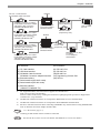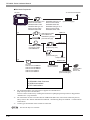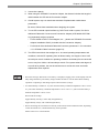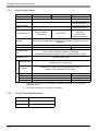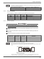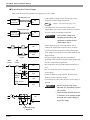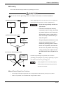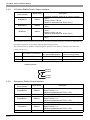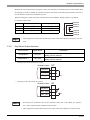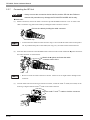
1
*3+6HULHV +DUGZDUH0DQXDO Preface Thank you for purchasing Pro-face's GP3000H Series Programmable Operator Interface (Hereafter referred to as the “GP unit”). Before operating your GP unit, be sure to read this manual to familiarize yourself with the GP unit's operation procedures and features. NOTICE 1. Copying this manual's contents, either in whole or in part, is prohibited without the express permission of Digital Electronics Corporation, Japan. 2. The information contained in this manual is subject to change without notice. 3. Should you find any errors or omissions in this document, please contact Digital Electronics Corporation to report your findings. 4. Regardless of Clause 3 above, Digital Electronics Corporation shall not be held responsible for any damages, losses or third-party damages resulting from the use of this product. © 2008 Copyright Digital Electronics Corporation. All rights reserved. Product names used in this manual are the trademarks / registered trademarks of their respective owners. 1 Essential Safety Precautions All safety-related procedures stated in this document must be followed to operate the GP correctly and safely. Be sure to read this and any related documents thoroughly to understand the correct operation and functions of the GP unit. Safety Icons Throughout this manual, these icons provide essential safety information for GP operation procedures requiring special attention. These icons indicate the following levels of danger: Indicates situations where severe bodily injury, death or major equipment damage can occur. Indicates situations where slight bodily injury or minor equipment damage can occur. Indicates actions or procedures that should NOT be performed. Indicates actions or procedures that MUST be performed to ensure correct unit operation. System Design Do not make switches using the switches on the touch panels which may cause operator injury and machine damage. An output may remain either ON or OFF due to a malfunction of the GP unit, it’s I/O unit(s) or cable(s), which may cause a major accident. To prevent this, set up circuits such as limiters that will monitor vital output signals. Design switches for important operations to be performed by separate devices. An incorrect output or malfunction can occur and thereby cause an accident. Do not create GP touch panel switches to control machine safety operations, such as an emergency stop switch. Install these switches as separate hardware switches, otherwise severe bodily injury or equipment damage can occur. Be sure to design your system so that a communication fault between the GP and its host controller will not cause equipment to malfunction. This is to prevent any possibility of bodily injury or equipment damage. Do not use the GP as a warning device for critical alarms that can cause serious operator injury, machine damage or can halt system operation. Critical alarm indicators and their control/activator units must be designed using stand-alone hardware with redundancy and/or mechanical interlocks. Do not use the GP with aircraft control devices, aerospace equipment, central trunk data transmission (communication) devices, nuclear power control devices, or medical life support equipment, due to these devices' inherent requirements of extremely high levels of safety and reliability. 2 When using the GP with transportation vehicles (trains, cars, and ships), disaster and crime prevention devices, various types of safety equipment, and medical devices that are not life-support related, use redundant and/or failsafe system designs to ensure proper reliability and safety. After the GP unit's backlight burns out the touch panel is still active, unlike the GP unit's "Standby Mode". If the operator fails to notice that the backlight is burned out and touches the panel, a potentially dangerous machine operation error can occur. Therefore, do not create GP unit touch panel switches that may cause injury and/or equipment damage. If your GP unit's backlight suddenly turns OFF, use the following steps to determine if the backlight is actually burned out. 1) If the GP unit's "Backlight Control" is not set and the screen has gone blank, your backlight is burned out. 2) If the GP unit's "Backlight Control" is set to Standby Mode and the screen has gone blank, and touching the screen or performing another input operation does not cause the display to reappear, your backlight is burned out. Handling Do not disassemble or modify the GP unit. Doing so may cause a fire or an electric shock. Do not operate the GP in an environment where flammable gases are present, since it may cause an explosion. Wiring To prevent electrical shock or equipment damage, unplug the GP unit's power cord from the power supply prior to installing or wiring the GP. To prevent an electric shock, be sure to disconnect your GP unit's power cord from the power supply before wiring the GP. Do not use voltage beyond the GP unit's specified range. Doing so may cause a fire or an electric shock. Maintenance Do not connect or disconnect Host and GP unit communication cables while the GP is turned ON. Do not replace the GP unit's battery yourself. The GP uses a lithium battery for backing up its internal clock data and the battery may explode if it is replaced incorrectly. When replacement is required, please contact your local GP distributor. 3 Installation Be sure all cable connectors are securely attached to the GP unit. A loose connection may cause incorrect input or output signals. Wiring Be sure to ground the GP unit's FG wire separately from other equipment FG lines. Also, be sure to use a grounding resistance of 100 or less and a 2mm2 or thicker wire, or your country's applicable standard. Otherwise, electric shock or malfunctions may result. Be sure that metal particles and wiring debris do not fall inside the GP unit. They can cause a fire, malfunction or incorrect unit operation. Maintenance Be sure to turn the GP unit's CF Card ACCESS switch OFF and confirm that the ACCESS lamp is not lit prior to inserting or removing a CF Card. Otherwise, CF Card internal data may be damaged or lost. Do not reset or turn the GP OFF, or insert or remove the CF Card while the GP unit's CF Card is being accessed. Create special application screens to perform operations like turning power OFF, resetting the GP or inserting or removing the CF Card. Unit Disposal When the product is disposed of, it should be disposed of in a manner appropriate to, and in accordance with, the user country's industrial machinery disposal/recycling standards. General Safety Precautions Do not press on the GP unit's display with excessive force or with a hard object, since it can damage the display. Also, do not press on the touch panel with a pointed object, such as the tip of a mechanical pencil or a screwdriver, since doing so can damage the touch panel. Do not install the GP where the ambient temperature exceeds the specified range. Doing so may cause a unit malfunction. To prevent abnormally high temperatures from occurring inside the GP, do not restrict or block the GP unit's rear-face ventilation slots. Do not operate the GP in areas where large, sudden temperature changes can occur. These changes can cause condensation to form inside the GP, possibly causing it to malfunction. Do not allow water, liquids or metal fragments to enter inside the GP unit's case, since they can cause either a malfunction or an electric shock. The allowable pollution degree is 2. 4 Do not operate or store the GP in locations where it can be exposed to direct sunlight, high temperatures, excessive dust, moisture or vibration. Do not operate or store the GP where chemicals evaporate, or where chemicals are present in the air. Corrosive chemicals: Acids, alkalines, liquids containing salt Flammable chemicals: Organic Solvents Do not use paint thinner or organic solvents to remove dirt or oil from the GP unit's surface. Instead, use a soft cloth moistened with a diluted neutral detergent. Do not use or store the GP in areas with direct sunlight, since the sun's ultraviolet rays may cause the LCD's quality to deteriorate. The cover on the insertion hole for function switch sheet may deteriorate when used in environments that experience high levels of ozone or extreme cold. If moisture remains on the cover on the insertion hole for function switch sheet when inserted, it may eventually peel off. Please dry the cap on insertion. Do not store the GP in an area where the temperature is lower than that recommended in the GP unit's specifications. Doing so may cause the LCD display's liquid to congeal, which can damage the LCD. Also, if the storage area's temperature becomes higher than the specified level, the LCD's liquid may become isotropic, causing irreversible damage to the LCD. Therefore, only store the GP in areas where temperatures are within the GP unit's specifications. After turning OFF the GP, be sure to wait a few seconds before turning it ON again. The GP may not operate correctly if it is restarted too quickly. Be sure to back up the GP screen data in case they are lost accidentally. LCD Panel Usage Precautions • The LCD panel's liquid contains an irritant. If the panel is damaged and any of this liquid contacts your skin, immediately rinse the area with running water for at least 15 minutes. If the liquid gets in your eyes, immediately rinseyour eyes with running water for at least 15 minutes and consult a doctor. • The GP unit's LCD screen may flicker or show unevenness in the brightness of certain images or at some contrast settings. This is an LCD characteristic and not a product defect. • There’s an individual difference in brightness and tone of LCD screen. Please be aware of this difference before using the lined-up plural units. • Depending on the ambient temperature, LCD displays may sometimes look whitish (at high temperatures) or blackish (at low temperatures). This is an LCD characteristic and not a product defect. • Some of GP unit's LCD screens may contain black and white colored pixels. This is an LCD characteristic and not a product defect. 5 • Extended shadows, or “Crosstalk” may appear on the sides of screen images. This is an LCD characteristic and not a product defect. • The color displayed on the GP unit's LCD screen may appear different when seen from outside the specified viewing angle. This is an LCD characteristic and not a product defect. • When the same image is displayed on the GP unit's screen for a long period, an afterimage may appear when the image is changed. This is an LCD characteristic and not a product defect. • To prevent an afterimage: * Set the GP unit's display OFF feature when you plan to display the same screen image for a long period of time. * Change the screen image periodically and try to not display the same image for a long period of time. • Please be aware that characteristics of the GP unit's LCD screen with a white LED backlight may change gradually owing to the deterioration of the backlight LED and the LCD display may look bluish. 6 Information Symbols This manual uses the following icons: Indicates a warning or a product limitation. Be sure to follow the instructions given with this icon to ensure the safe operation of the GP. Screen Editor Indicates the GP-Pro EX software. PLC Abbreviation for Programmable Logic Controller. * Indicates useful or important supplemental information. Contains additional or useful information. SEE Indicates pages containing related information. About the Manuals For the detailed information on GP3000H Series, refer to the following manuals. • Maintenance/Troubleshooting For the Offline Settings, see Maintenance/Troubleshooting (Offline Settings Guide). • GP-Pro EX Device/PLC Connection Manual "GP3000H Series Connection Guide" • GP-Pro EX Reference Manual "Hand-held GP" The manuals can be downloaded from Pro-face website "Otasuke Pro!". URL http://www.pro-face.com/otasuke/ 7 GP3000H Series Model Name Indication Model name A G P 3 * **H - * 1 - *** - ****- *** A B A B C D E F 3 00 10 L S T D24 None RED YEL GRY None KEY C D E F 5.7-inch AGP-3300HL/AGP-3300HS: QVGA (320 x 240 pixels) QVGA (320 x 240 pixels) AGP-3310HT: VGA (640 x 480 pixels) VGA (640 x 480 pixels) Monochrome LCD STN color LCD TFT color LCD DC type power supply is used. No Emergency Switch Emergency Switch : RED Emergency Switch : YELLOW Emergency Switch : GRAY No Key Switch Key Switch is used. GP3000H Series Model Names The term "GP3000H" Series refers to the following GP model numbers: Series GP3000 series 8 GP3000H series Names AGP-3300HL AGP-3300HS AGP-3310HT Models AGP3300H-L1-D24 AGP3300H-S1-D24 AGP3310H-T1-D24 Package Contents The following items are included in the GP unit's package. Before using the GP, please check that all items listed here are present. GP Unit: 1 • English and Japanese Installation Guides (1 of each) Hand Strap: 1 Hanger: 1 (Attached to the GP unit) The hanger is used to hang the GP unit on a wall. • Warning/Caution Information (1) Emergency Switch Guard: 1 Attachment Screws: 3 Function Switch Sheet: (Only for the GP unit with the Emergency Switch) 1 set (Attached to the GP unit) 5 sets (for replacement) Touch Pen: 1 (Attached to the GP unit) Connector Cover: 1 (Attached to the GP unit) This unit has been carefully packed, with special attention to quality. However, should you find anything damaged or missing, please contact your local GP distributor immediately. About Revision The nameplate on the GP has the revision number of the GP. In the example below, the asterisk, which is placed at the “A” position, shows that the revision number is “A”. 9 Installation prerequisites for standards • UL listed products*1 Industrial Control Equipment refer to UL508 see [a] in the “Product List“ refer to CSA-C22.2 No.142 see [b] in the “Product List“ • c-UL listed products*1 Standard for Process Control Equipment • Product List Product Model No. Registration Model No. UL c-UL [a] [b] AGP3300H-L1-D24 3610005-03 AGP3300H-S1-D24 3610005-02 AGP3310H-T1-D24 3610005-01 UL/c-UL File No.: E220851 For the detailed certification's information, refer to the Pro-face website. <Cautions> Be aware of the following item when building the GP into an end-use product: • The GP unit must be used indoors only. *1 The system constructing the following three components conform to UL/c-UL standards: •GP3000H •GP3000H Direct-connect Cable (with connector) GP3000H-CBLHD-10M, GP3000H-CBLSD-3M, GP3000H-CBLSD-5M, GP3000H-CBLSD-10M •GP3000H Conversion Adapter AGP3000H-ADPCOM-01 The safety certificate can be downloaded from Pro-face website. Home Page URL http://www.pro-face.com/ CE Marking The following units are CE marked products complying with the EMC Directive. AGP3300H-L1-D24 AGP3300H-S1-D24 AGP3310H-T1-D24 For the detailed information on CE Marked, be downloaded and refer the Declaration of Conformity from Pro-face website. Home Page URL http://www.pro-face.com/ 10 Contents Preface ...................................................................................................................... 1 Essential Safety Precautions..................................................................................... 2 Information Symbols.................................................................................................. 7 About the Manuals .................................................................................................... 7 GP3000H Series Model Name Indication.................................................................. 8 GP3000H Series Model Names ................................................................................ 8 Package Contents ..................................................................................................... 9 About Revision .......................................................................................................... 9 Installation prerequisites for standards.................................................................... 10 CE Marking.............................................................................................................. 10 Contents ..................................................................................................................11 Chapter 1 Overview 1.1 System Design................................................................................................ 1-2 1.1.1 Restrictions ..........................................................................................................1-7 1.2 Accessories .................................................................................................... 1-8 1.2.1 GP3000H Cable Connector .................................................................................1-8 1.2.2 USB Host Interface ..............................................................................................1-9 1.2.3 CF Card Items ...................................................................................................1-10 1.2.4 Option Items ......................................................................................................1-10 1.2.5 Maintenance Items ............................................................................................1-10 1.2.6 Peripheral options for the GP3000H Conversion Adapter .................................1-10 1.2.7 Maintenance options for the GP3000H Conversion Adapter.............................1-12 1.2.8 Peripheral options for the GP2000H Series RS-232C Conversion Adapter ......1-12 1.2.9 Peripheral options for the GP2000H Series RS-422 Conversion Adapter.........1-12 1.3 Part Names and Functions ........................................................................... 1-13 Chapter 2 Specifications 2.1 General Specifications .................................................................................... 2-2 2.1.1 Electrical Specifications .......................................................................................2-2 2.1.2 Environmental Specifications...............................................................................2-2 2.1.3 External Specifications ........................................................................................2-3 2.2 Performance Specifications ............................................................................ 2-4 2.2.1 Performance Specifications .................................................................................2-4 2.2.2 Display Specifications..........................................................................................2-6 2.2.3 Touch Panel Specifications ..................................................................................2-6 2.3 Connection with Peripheral Equipment........................................................... 2-7 11 2.3.1 Serial Interfaces...................................................................................................2-8 2.3.2 Ethernet Interface ................................................................................................2-9 2.3.3 DC24V Interface ..................................................................................................2-9 2.3.4 3-Position Enable Switch Output Interface ........................................................2-12 2.3.5 Emergency Switch Output Interface ..................................................................2-12 2.3.6 Key Switch Output Interface ..............................................................................2-13 2.3.7 Connecting the GP Unit .....................................................................................2-14 2.4 Dimensions ................................................................................................... 2-16 2.4.1 Dimensions ........................................................................................................2-16 2.4.2 External Dimensions of the Emergency Switch Guard ......................................2-16 Chapter 3 Fixing the GP and Attaching Accessories 3.1 Fixing the GP3000H ....................................................................................... 3-2 3.1.1 Hand Strap...........................................................................................................3-2 3.1.2 Neck Strap ...........................................................................................................3-3 3.1.3 Wall Mount Adapter .............................................................................................3-3 3.2 Instructions for Mounting Accessories ............................................................ 3-4 3.2.1 Attaching the Emergency Switch Guard ..............................................................3-4 3.2.2 Replacing the Function Switch Sheets ................................................................3-5 3.3 CF Card Insertion/Removal ............................................................................ 3-6 3.3.1 Inserting the CF Card ..........................................................................................3-7 3.3.2 Removing the CF Card ........................................................................................3-8 3.3.3 CF Card Handling ................................................................................................3-8 Chapter 4 Maintenance 4.1 Cleaning the Display....................................................................................... 4-2 4.2 Periodic Check Points..................................................................................... 4-3 4.3 Replacing the Backlight .................................................................................. 4-4 After-sales sevice 12 1 Overview 1. System Design 2. Accessories 3. Part Names and Functions 1-1 GP3000H Series Hardware Manual 1.1 System Design The following diagram illustrates the standard range of items that can be connected to GP-3000H Series unit. For host controller (PLC, etc.) connection information, refer to the "GP-Pro EX Device/PLC Connection Manual". GP RUN Mode Peripherals GP Unit (1) (2) CA3-CFCALL/128MB-01 CF Card CA3-CFCALL/256MB-01 CA3-CFCALL/512MB-01 CA6-CFCALL/1GB-01 CA8-CFCALL/2GB-01 USB-to-IEEE1284 Conversion Cable (Commercial type) Bar-Code Reader*1 (Commercial type) Printer*1 (Commercial type) USB Cable FP-US00 or commercial type USB Memory Strage*1 (Commercial type) Bar-Code Reader*1 (Commercial type) USB-Serial (RS-232C) Conversion Cable CA6-USB232-01 (3) GP3000H Hard-type 10 m Direct-connect Cable GP3000H-CBLH-10M GP3000H Soft-type 3 m Direct-connect Cable GP3000H-CBLS-3M GP3000H Soft-type 5 m Direct-connect Cable GP3000H-CBLS-5M GP3000H Soft-type 10 m Direct-connect Cable GP3000H-CBLS-10M Continued 1-2 To an Ethernet Network Hub (commercial type) 24 VDC Power Supply Unit (Commercial type) Host Controller PLC etc. Chapter 1 Overview GP Unit – Continued from the GP3000H Cable Connector (8) (3) GP3000H Hard-type 10 m Direct-connect Cable (with connector) GP3000H-CBLHD-10M RS-232C Cable CA3-CBL232/5M-01 GP3000H Conversion Adapter AGP3000H-ADPCOM-01 (8) Mitsubishi PLC Q-Series Link Cable CA3-CBLLNKMQ-01 (8) GP3000H Soft-type 5 m Direct-connect Cable (with connector) GP3000H-CBLSD-5M Omron PLC SYSMAC Link Cable CA3-CBLSYS-01 (8) GP3000H Soft-type 10 m Direct-connect Cable (with connector) GP3000H-CBLSD-10M Mitsubishi PLC Q-Series Connection Cable (12) CA3-CBLQ-01 GP3000H Soft-type 3 m Direct-connect Cable (with connector) GP3000H-CBLSD-3M (4) (5) Host Controller PLC etc. Siemens TTY Converter Cable CA6-CBLTTY/5M-01 (8) RS-232C Isolation Unit CA3-ISO232-01 RS-232C Cable CA3-CBL232/5M-01 Switch setting :RS-232C Mitsubishi PLC Q-Series Link Cable CA3-CBLLNKMQ-01 (8) Omron PLC SYSMAC Link Cable CA3-CBLSYS-01 (8) (8) Host Controller PLC etc. Mitsubishi PLC Q-Series Connection Cable CA3-CBLQ-01 (12) Siemens TTY Converter Cable CA6-CBLTTY/5M-01 (9) RS-232C Isolation Unit CA3-ISO232-01*2,3 Switch setting :RS-422 RS-422 Cable CA3-CBL422/5M-01 (9) COM Port Conversion Adapter CA3-ADPCOM-01 RS-422 Cable CA3-CBL422-01 (11) 2 Port Mitsubishi PLC A, QnA, Adapter Cable FX Series' 2 Port Adapter II CA3-MDCB11 GP070-MD11 (9) Continued Continued Terminal Block Conversion Adapter CA3-ADPTRM-01 RS-422 Cable (Prepared by user) • When connecting the CA3-ISO232-01, the 9 Pin's setting of COM port is required to be VCC. COM port settings can be set with the GP-Pro EX or in GP's offline mode. 1-3 GP3000H Series Hardware Manual GP Unit – Continued from the GP3000H Cable Connector (3) Continued from GP3000H Conversion Adapter (6) MPI Cable ST03-A2B-MPI21-PFE Mitsubishi PLC FX-Series Connection Cable CA3-CBLFX/1M-01 CA3-CBLFX/5M-01 Mitsubishi PLC A-Series Connection Cable CA3-CBLA-01 (10) (11) (11) (9) RS-422 Cable CA3-CBL422/5M-01 COM Port Conversion Adapter CA3-ADPCOM-01 RS-422 Cable CA3-CBL422-01 (11) 2 Port Adapter Cable CA3-MDCB11 Mitsubishi PLC A, QnA, FX Series' 2 Port Adapter II GP070-MD11 (9) Multi-Link Cable CA3-CBLMLT-01 (9) Terminal Block Conversion Adapter CA3-ADPTRM-01 RS-422 Cable (Prepared by user) To an Ethernet Network (7) Continued 1-4 Twisted pair Cable (Commercial type) HUB (Commercial type) Host Controller PLC etc. Chapter 1 Overview DC24V GP Unit – Continued from the GP3000H Cable Connector (8) (3) GP3000H Soft-type 3 m Cable for GP2000H Conversion Adapter <RS-232C> (with connector) GP3000H-CBLSD232-3M*4 GP2000H RS-232C Conversion Adapter GP2000H-AP232 RS-232C Cable GP410-IS00-O*5 Host Controller PLC etc. RS-232C Cable (Prepared by user) GP3000H Soft-type 10 m Cable for GP2000H Conversion Adapter <RS-232C> (with connector) GP3000H-CBLSD232-10M*4 DC24V (9) GP3000H Soft-type 3 m Cable for GP2000H Conversion Adapter <RS-422> (with connector) GP3000H-CBLSD422-3M*4 RS-422 Cable GP2000H RS-422 (Prepared by user) Conversion Adapter GP2000H-AP422 Mitsubishi PLC A, QnA, FX Series' 2 Port Adapter II GP070-MD11 GP3000H Soft-type 10 m Cable for GP2000H Conversion Adapter <RS-422> (with connector) GP3000H-CBLSD422-10M*4 GP Interfaces PLC Interfaces (1) CF Card Interface (2) USB Host Interface (3) GP3000H Cable Connector GP3000H Conversion Adapter Interface (4) External Interface (5) Serial Interface (RS-232C mode) (6) Serial Interface (RS-422 mode) (7) Ethernet Interface (10BASE-T/100BASE-TX) (8) RS-232C Port (9) RS-422 Port (10) RS-485 Port (11) Programming Console Port (12) PG Port *1 Host Controller PLC etc. For supported models, refer to Pro-face’s support site “Otasuke Pro!” (http://www.pro-face.com/otasuke/). You can connect to this site by clicking the GP-Pro EX’s [Help (H)] menu-[Connect to Support Site “Otasuke Pro!” (O)] command. *2 The RS-232C Isolation Unit does not correspond to RS-422/485 (2 wire) communication. *3 The RS-232C Isolation Unit does not correspond to Serial Multilink communication. *4 Be sure to read the restrictions when connecting GP3000H to any external devices using GP2000H RS232C or RS-422 Conversion Adapter and this cable. SEE *5 SEE 1.1.1 Restrictions (page1-7) Certain types and models of PLCs cannot be connected. GP-Pro EX Device/PLC Connection Manual "GP3000H Series Connection Guide" 1-5 GP3000H Series Hardware Manual Edit Mode Peripherals To an Ethernet Network GP Unit (1) GP3000H Hard-type 10 m Direct-connect Cable GP3000H-CBLH-10M GP3000H Soft-type 5 m Direct-connect Cable GP3000H-CBLS-5M GP3000H Soft-type 3 m Direct-connect Cable GP3000H-CBLS-3M GP3000H Soft-type 10 m Direct-connect Cable GP3000H-CBLS-10M (2) HUB (Commercial type) USB Port USB Transfer Cable CA3-USBCB-01 USB Memory Strage*1 (Commercial type) Serial Port USB-Serial (RS-232C) Conversion Cable CA6-USB232-01 RS-232C Cable*2 (Prepared by user) Modem*1 (Commercial type) Telephone lines (3) PCMCIA Slot CF Card CA3-CFCALL/128MB-01 CA3-CFCALL/256MB-01 CA3-CFCALL/512MB-01 CA6-CFCALL/1GB-01 CA8-CFCALL/2GB-01 CF Card Adapter GP077-CFAD10 Personal Computer*3 (Commercial type) Screen Editor Software GP-Pro EX GP Interfaces (1) GP3000H Cable Connector (2) USB Host Interface (3) CF Card Interface *1 For supported models, refer to Pro-face’s support site “Otasuke Pro!” (http://www.pro-face.com/otasuke/). You can connect to this site by clicking the GP-Pro EX’s [Help (H)] menu-[Connect to Support Site “Otasuke Pro!” (O)] command. *2 For instructions on how to connect between USB-Serial (RS-232C) Conversion Cable and your PC, always refer to the “GP-Pro EX Reference Manual ->Transferring Projects and Data -> COM Transfer Connections”. *3 Certain types and models of PCs cannot be connected. SEE 1-6 GP-Pro EX Reference Manual Chapter 1 Overview 1.1.1 Restrictions Please be aware of the following restrictions when using the GP2000H RS-232C/RS-422 Conversion Adapter (Hereafter referred to as the "GP2000H Conversion Adapter") to connect the GP3000H to peripheral equipment. • The GP3000H cannot be connected to Ethernet networks. • For GP3000Hs mounted with key switches, outputting to peripheral equipment by turning the GP3000H key switch is not possible. The GP3000H’s power supply can be turned ON/OFF by turning the GP3000H key switch. • The cable cannot be unplugged from the GP2000H Conversion Adapter without causing an emergency stop by providing an external safety circuit. • The operation switch and function keys cannot be used for functions involving signal outputting to peripheral equipment. Example: Function keys designed to activate external buzzers, etc. • Data set ready “DR (DSR)” signals cannot be used when connecting to peripheral equipment using RS232C connections. • The GP2000H Conversion Adapter does not comply with UL dust and drip proofing standards. • Pro-face’s GP3000H Conversion Adapter (model: AGP3000H-ADPCOM-01) and a dedicated cable (sold separately) are necessary to overcome these restrictions. SEE 1.2 Accessories (page1-8) 1-7 GP3000H Series Hardware Manual 1.2 Accessories All accessories listed here are produced by Pro-face. 1.2.1 GP3000H Cable Connector Accessories for connecting the external devices to GP3000H directly Product Name Model No. GP3000H Hard-type 10 m Direct-connect Cable GP3000H-CBLH-10M GP3000H Soft-type 3 m Direct-connect Cable GP3000H-CBLS-3M GP3000H Soft-type 5 m Direct-connect Cable GP3000H-CBLS-5M GP3000H Soft-type 10 m Direct-connect Cable GP3000H-CBLS-10M Description Heavy-duty type interface cable for communication between the GP and external equipment (e.g. host controller), equipped with common mode filter. Standard type interface cable for communication between the GP and external equipment (e.g. host controller), equipped with common mode filter. Accessories for connecting GP3000H Conversion Adapter to GP3000H Product Name GP3000H Hard-type 10 m Direct-connect Cable (with connector) GP3000H-CBLHD-10M GP3000H Soft-type 3 m Direct-connect Cable (with connector) GP3000H-CBLSD-3M GP3000H Soft-type 5 m Direct-connect Cable (with connector) GP3000H-CBLSD-5M GP3000H Soft-type 10 m Direct-connect Cable (with connector) GP3000H-CBLSD-10M GP3000H Conversion Adapter 1-8 Model No. AGP3000H-ADPCOM-01 Description Heavy-duty type cable between the GP3000H Conversion Adapter and the GP3000H. Standard type cable between the GP3000H Conversion Adapter and the GP3000H. Conversion Adapter for interfacing with a GP3000H Cable Connector and External Output I/F output the following connectors; serial: D-Sub 9 pin (plug), Ethernet: modular jack (RJ-45), others: terminal block. Chapter 1 Overview Accessories for connecting GP2000H Series RS-232C or RS-422 Conversion Adapter to GP3000H Product Name GP3000H Soft-type 3 m Cable for GP2000H Conversion Adapter <RS232C> (with connector)*1 GP3000H-CBLSD232-3M GP3000H Soft-type 10 m Cable for GP2000H Conversion Adapter <RS232C> (with connector)*1 GP3000H-CBLSD232-10M GP2000H Series RS-232C Conversion Adapter *1 GP2000H-AP232 GP3000H Soft-type 3 m Cable for GP2000H Conversion Adapter <RS422> (with connector) *1 GP3000H-CBLSD422-3M GP3000H Soft-type 10 m Cable for GP2000H Conversion Adapter <RS422> (with connector)*1 GP3000H-CBLSD422-10M GP2000H Series RS-422 Conversion Adapter *1 GP2000H-AP422 *1 Description The cable between the GP2000H Series RS-232C Conversion Adapter and the GP3000H, equipped with D-Sub connector. Conversion adapter to connect GP operation data to RS-232C D-Sub and power/DIO terminals. The cable between the GP2000H Series RS-422 Conversion Adapter and the GP3000H, equipped with D-Sub connector. Conversion adapter to connect GP operation data to RS-422 and power/DIO terminals. Be sure to read the restrictions to use the accessories. 1.1.1 Restrictions (page1-7) SEE 1.2.2 Model No. USB Host Interface Product Name Model No. Description USB Transfer Cable CA3-USBCB-01 (2m) Downloads project data created with the Screen Editor via the GP unit's USB I/F. USB Cable FP-US00 (5m) Connects a USB printer. (TYPE-B) CA6-USB232-01(0.5m) Cable for converting a GP unit's USB interface into a serial interface (RS-232C). Allows connection to modems*1 or barcode readers*1 that support RS-232C. Can be used to transfer project data created with the Screen Editor via a serial interface.*2 USB-Serial (RS-232C) Conversion Cable *1 *2 For supported models, refer to Pro-face’s support site “Otasuke Pro!” (http://www.pro-face.com/otasuke/). You can connect to this site by clicking the GP-Pro EX’s [Help (H)] menu-[Connect to Support Site “Otasuke Pro!” (O)] command. Requires an RS-232C cable (prepared by user) for connection. For details regarding system design, refer to " Edit Mode Peripherals (page1-6)". For instructions on how to connect between USB-Serial (RS-232C) Conversion Cable and your PC, always refer to the "GP-Pro EX Reference Manual -> Transferring Projects and Data -> COM Transfer Connections". 1-9 GP3000H Series Hardware Manual 1.2.3 CF Card Items Product Name 1.2.4 CF Card (128MB) CA3-CFCALL/128MB-01 CF Card (256MB) CA3-CFCALL/256MB-01 CF Card (512MB) CA3-CFCALL/512MB-01 CF Card (1GB) CA6-CFCALL/1GB-01 CF Card (2GB) CA8-CFCALL/2GB-01 CF Card Adapter GP077-CFAD10 Description Inserted into the GP unit's CF Card slot. Used for read/write of CF Card data via a PC's PCMCIA slot. Option Items Product Name 1.2.5 Model No. Model No. Description Screen Protection Sheet GP3000H-DFS6-01 Disposable, dirt-resistant sheet for the GP unit's screen. (5 sheets/set) (Hard type) Neck Strap GP2000H-STRAP11 Strap for wearing over the neck. Wall Hanging Adapter GP3000H-WMA-01 Bracket for mounting the GP3000H Series unit to a commercially available arm or panel. Touch Pen CA7-TPPEN/ALL-01 5 touch pens for screen operation. Maintenance Items GP accessories. Sold separately as an option for maintenance. Product Name Hand Strap Description GP3000H-HS-01 Strap for handheld operation. Emergency Switch Guard GP3000H-EMGD-01 Emergency Switch Guard for preventing accidental operation. Function Switch Sheet*1 GP3000H-DUPS-01 5 sheets/set (x 5) for changing image of the function switches. *1 1.2.6 Model No. For the Function Switch Sheet for printing, refer to Pro-face's support site "Otasuke Pro!" (http://www.pro-face.com/otasuke/). You can connect to this site by clicking the GP-Pro EX's [Help (H)] menu-[Connect to Support Site "Otasuke Pro!" (O)] command. Peripheral options for the GP3000H Conversion Adapter Optional parts for the GP3000H Conversion Adapter (hereinafter, “this adapter”). Product Name 1-10 Model No. Description RS-232C Cable CA3-CBL232/5M-01 (5m) Connects Mitsubishi PLC A-Series (or other host controller) to this adapter. (RS-232C) RS-422 Cable CA3-CBL422/5M-01 (5m) Connects a host controller to this adapter. (RS-422 / Socket Type) Chapter 1 Overview Product Name Model No. Description Mitsubishi PLC Q-Series Link Cable CA3-CBLLNKMQ-01 (5m) Connects Mitsubishi PLC Q-Series (or other host controller) to this adapter. (RS-232C) Omron PLC SYSMAC Link Cable CA3-CBLSYS-01 (5m) Connects Omron PLC SYSMAC Series unit (or other host controller) to this adapter. (RS-232C) CA3-CBLA-01 (5m) Connects Mitsubishi PLC A, QnA Series programming console I/F to this adapter. (Simultaneous use of programming console is not possible.) Mitsubishi PLC Q-Series Connection Cable CA3-CBLQ-01 (5m) Connects Mitsubishi PLC Q-Series programming console I/F to this adapter. (Simultaneous use of programming console is not possible.) Mitsubishi PLC FX-Series Connection Cable CA3-CBLFX/1M-01 (1m) CA3-CBLFX/5M-01 (5m) Connects Mitsubishi PLC FX-Series programming console I/F and this adapter. (Simultaneous use of programming console is not possible.) 9-pin-to-25-pin RS-232C Conversion Cable CA3-CBLCBT232-01 (0.2m) D-sub 9-pin plug to D-sub 25-pin socket conversion cable 9-pin-to-25-pin RS-422 Conversion Cable CA3-CBLCBT422-01 (0.2m) D-sub 9-pin socket to D-sub 25-pin socket conversion cable RS-422 Cable CA3-CBL422-01 (5m) Connects a host controller to this adapter. (RS-422 / Plug Type) 2 Port Adapter Cable CA3-MDCB11 (5m) Connects Mitsubishi PLC to this adapter using 2 port Adapter II (RS-422). Mitsubishi PLC A, QnA, FX Series 2 Port Adapter II GP070-MD11 Allows simultaneous use of this adapter and a Mitsubishi PLC A, QnA, FX Series peripheral device. Multi-Link Cable CA3-CBLMLT-01 (5m) Connects a host controller to this adapter for multi-link (n:1) communication. Terminal Block Conversion Adapter CA3-ADPTRM-01 Connects output from a serial interface with an RS-422 terminal block. COM Port Conversion Adapter CA3-ADPCOM-01 Connects optional RS-422 communication items to this adapter’s COM port. Siemens COM Port Conversion Adapter CA3-ADPSEI-01 Connects Siemens PLCs to this adapter. (for RS-485 communication) Siemens TTY Converter Cable CA6-CBLTTY/5M-01 (5m) Connects Siemens PLC S5 Series to this adapter. MPI Cable ST03-A2B-MPI21-PFE (3.5m) Connects a host controller to this adapter for MPI communication. RS-232C Isolation Unit CA3-ISO232-01 Connects a host controller to this adapter with provides isolation. (RS-232C and RS-422 are switchable.) Hub SPIDER8TX-PRO For all models with an Ethernet I/F Industrial Ethernet HUB DC24 Mitsubishi PLC A-Series Connection Cable 1-11 GP3000H Series Hardware Manual 1.2.7 Maintenance options for the GP3000H Conversion Adapter Accessory to the GP3000H Conversion Adapter. Sold separately as an option for maintenance. Product Name Installation Gasket 1.2.8 RS-232C Cable *1 SEE Provides dust and moisture resistance when GP3000H Conversion Adapter is installed into a solid panel. Model No. GP410-IS00-0*1 Description Connects the GP2000H Series RS-232C Conversion Adapter and Host (PLC). Certain types and models of PCs cannot be used. GP-Pro EX Device/PLC Connection Manual "GP3000H Series Connection Guide" Peripheral options for the GP2000H Series RS-422 Conversion Adapter Product Name Mitsubishi PLC A, QnA, FX Series’ 2 Port Adapter II 1-12 GP3000H-WPGADP-01 Description Peripheral options for the GP2000H Series RS-232C Conversion Adapter Product Name 1.2.9 Model No. Model No. GP070-MD11 Description Allows simultaneous use of a GP Series unit and a Mitsubishi PLC A, QnA, FX Series peripheral device. Chapter 1 Overview 1.3 Part Names and Functions A: Status LED (POWER) This LED indicates the GP's status, e.g. power input, firmware RUN status or backlight condition. E Color Indicator A B C Operation Mode OFFLINE Green ON Red ON When power is turned on. ON Backlight burnout or GP malfunction*1 Flashing During software startup Orange In operation OFF *1 D Front Power is OFF. When backlight replacement or repair of the GP is required, please contact your local GP distributor. B: Operation LED (O.P.) LED CF Card Cover Open G GP Status Indicates the Operation Switch is Green ON. Not Lit Indicates the Operation Switch is OFF. C: Operation Switch When this switch is enabled, the GP unit can accept touch panel input and function key input, only while this switch is being pressed. G Top F H I J, K D: Function Switches (11 switches) The switch functions are set up with the screen design software. For details, refer to the GP-Pro EX Reference Manual. E: Emergency Switch F: Key Switch Turning the key turns ON/OFF the GP unit power supply. G: CF Card Cover The CF Card I/F, USB I/F, Dip Switches and LAN Status LED are located in the CF Card Cover open. • During operation of the GP unit, keep the CF Card cover closed. Operating the GP with the cover left open removes the dust-proof and droplet-proof protection. Doing so could cause a unit malfunction. 1-13 GP3000H Series Hardware Manual H: USB Host Interface Complies with USB 1.1. Uses a “TYPE-A” connector. Power supply voltage: DC5V±5%, Output current: 500 mA (max). Connect to the transfer cable, storage device (USB memory, CF Card reader), etc. The maximum communication distance: 5 m. CF Card Cover Open G I: CF Card Interface Insert the CF Card in this slot. G Top F H I J: DIP Switches J, K ON DIP Switches 1 2*1 3 4 Function ON 1 2 3 4 OFF Note CF Card Startup Settings (Controls unit startup from the CF Card.) Startup from CF Startup from CF CF Card with startup Card is enabled. Card is disabled. data required. Forced Transfer Mode Forced Transfer Mode: ON Reserved CF Card access setting *1 Forced Transfer Mode: OFF - - CF Card access enabled CF Card access disabled Constantly OFF - When power supply is turned ON and DIP Switch 2 is ON, it starts with Transfer Mode. Normally, set it to OFF. • After inserting a CF Card, be sure to turn ON DIP Switch 4, and close the CF Card cover before using the GP unit. • Before removing the CF Card, turn OFF DIP Switch 4 first, and make sure that the CF Card access LED turns off. If you remove the CF Card while the CF Card is being accessed (while the LED is lit), it may result in data corruption. K: LAN Status LED The LED turns on or off to indicate the current status of the Ethernet transmission interface (10BASE-T/ 100BASE-TX). LED Green ON Indicates Data transmission available Green Data transmission in progress. Flashing 1-14 Green OFF No connection or subsequent transmission failure Orange ON During connection with 100BASETX Orange OFF During connection with 10BASE-T or No connection Chapter 1 Overview G L F L: Hanger A hanger for temporarily hanging the GP unit on a wall. M Q R N • Do not operate or conduct wiring of the GP unit, with the GP unit hung on a wall. Otherwise, the GP may fall, resulting in injury or damage to the equipment. T O P O S Rear Right Side • The following is recommended to be used as pairs for this hanger; -A 7 or less, rod-shaped or S-shaped hook -M4 pan-head machine screw with head diameter 7 or less. -Panel thickness: 1 to 1.6mm [0.04 to 0.06 in.], Panel width: 14mm [0.55 in.] M: CF Card Access Lamp Access Lamp Indicates Green ON Indicates that a CF Card is inserted and DIP Switch 4 is set to ON, or that the CF Card is being accessed. Green OFF Indicates that DIP Switch 4 is set to OFF, or that no CF Card is inserted. N: 3-Position Enable Switch The switch provides three positions: A position where the switch is not pressed (released), a position where the switch is pressed to the intermediate position, and a position where the switch is pressed to the innermost position (fully pressed). O: Hand Strap Attachment Slots P: GP3000H Cable Connector (with Connector Cover) Connects the GP3000H dedicated cable. Q: Touch Pen R: Wall Adapter Attachment Slots To mount the GP unit to a panel or commercially available arm, attach the GP3000H dedicated wall hanging adapter (optional) to this hole. S: Insertion hole (with cover) for Function Switch Sheet. T: Neck Strap Attachment Slot 1-15 GP3000H Series Hardware Manual 1-16 2 Specifications 1. General Specifications 2. Performance Specifications 3. Connection with Peripheral Equipment 4. Dimensions This chapter describes the general, functional and interface specifications of the GP as well as its dimensions. 2-1 GP3000H Series Hardware Manual 2.1 General Specifications Electrical Specifications Power Supply 2.1.1 2.1.2 Input Voltage DC24V Rated Voltage DC19.2 to 28.8V Allowable Voltage Drop 10 ms (max.) Power Consumption 16.7 W (max.) In-Rush Current Voltage Endurance AC500V 20 mA for 1 minute (between charging and FG terminals) Insulation Resistance DC500V 10 M (min.) (between charging and FG terminals) Environmental Specifications Ambient Operating Temperature Physical Storage Temperature Mechanical -20 to +60°C Ambient Humidity Storage Humidity 10 to 90% RH (Wet bulb temperature: 39°C max. - no condensation.) Dust Atmosphere Electrical 0 to 40°C 10 to 90% RH (Wet bulb temperature: 39°C max. - no condensation.) Pollution Degree 2-2 60 A (max.) Half width (Time duration with a current exceeding 30 A): 40 µs max. 0.1 mg/m3 and below (non-conductive levels) For use in Pollution Degree 2 environment Free of corrosive gases Air Pressure Vibration Resistance (altitude range) 800 to 1,114hPa (2000 meters above sea-level maximum) Vibration Resistance IEC/EN61131-2 compliant 5 to 9 Hz single-amplitude 3.5 mm [0.14 in.] 9 to 150 Hz constant-accelerated velocity 9.8 m/s2 X,Y,Z directions for 10 cycle (100 minute) Concussion Resistance IEC/EN61131-2 compliant (147 m/s2 X,Y,Z directions for 3 time) Drop Resistance IEC61131-2 compliant 1.0 meter drop - 2 times. Noise Immunity Noise Voltage: 1,000 VP-P Pulse Duration: 1 s Rise Time: 1 ns (via noise simulator) Electrostatic Discharge Immunity 6 kV (complies with IEC/EN 61000-4-2 Level 3) Chapter 2 Specifications External Specifications Installation 2.1.3 Grounding Grounding resistance of 100 2 mm2 or thicker wire, or your country's applicable standard. (Same for FG and SG terminals) Structure *1 Rating: Equivalent to IP65f Cooling Method Natural air circulation Weight Approx. 1,000g [2.2 lb.] max. (GP without a Key Switch, unit only) 1,050g [2.3 lb.] max. (GP with a Key Switch, unit only) External Dimensions *1 W 224 mm [8.82 in.] X H 174 mm [6.85 in.] X D 87.1 mm [3.43 in.] (except an Emergency Switch) Even though the GP unit's level of resistance is equivalent to the standards shown in the specification, oils that should have no effect on the GP can possibly harm the unit. This can occur in areas where either vaporized oils are present, or where low viscosity cutting oils are allowed to adhere to the unit for long periods of time. If the GP's front face protection sheet becomes peeled off, these conditions can lead to the ingress of oil into the GP and separate protection measures are suggested. Also, if non-approved oils are present, it may cause deformation or corrosion of the front panel's plastic cover. Therefore, prior to installing the GP be sure to confirm the type of conditions that will be present in the GP's operating environment. 2-3 GP3000H Series Hardware Manual 2.2 Performance Specifications 2.2.1 Performance Specifications Application*1 External Output I/F*4 GP3000H Cable Connector Data Backup SRAM 320 KB (Used lithium battery for backup memory) Serial Interface RS-232C/RS-422/RS-485 Asynchronous Transmission: Data Length: 7 bit/8 bit Parity: none, Odd or Even Stop Bit: 1 bit/2 bit Data transmission Speed:2400 bps to 115.2 kbps 187.5 kbps (MPI) Maximum communication distance*2: 15 m (when using RS-232C), 1200 m (when using RS-422 at 115.2 kbps) Ethernet Interface Ethernet (IEEE802.3u,10BASE-T/100BASE-TX) Maximum communication distance*2: 100 m Emergency Switch Output Interface Push-lock switch 3 contacts; a-contact (normally open): 1contact, b-contact (normally closed): 2 contacts Rated voltage: DC30V Maximum rated current: 1 A (Minimum allowable load: DC5V, 1 mA) Applicable standards*3: ICE60947-5-1, EN60947-5-1, ICE60947-5-5, EN60947-5-5, UL508, CSA C22.2 No.14 3-Position Enable Switch Output Interface GP Rear panel switch 2 contacts (a-contact: normally open) Rated voltage: DC30V Maximum rated current: 700mA (Minimum allowable load: DC3V, 5 mA) Applicable standards*3 IEC60947-5-8, EN60947-5-8, UL508 (UL approval), CSA C22.2 No.14 (UL approval), ISO12100/EN12100-1,2, IEC60204-1/EN60204-1 ISO11161/prEN11161, ISO10218/EN775, ANSI/RIA R15.06, ANSI B11.19 Key Switch Output Interface 1c-contact (can be set normally open or normally closed.) Rated voltage: DC24V Maximum rated current: 300 mA DOUT Output Open Collector Output: 2 points (GP Front function switches, F1 and F2 keys) Rated Voltage: DC24V Rated Current: 300 mA/point max. Operation Output Open Collector Output: 1 point Rated Voltage: DC24V Rated Current: 300 mA max. External Buzzer Output Open Collector Output 1 point Rated Voltage: DC24V Rated Current: 300 mA max. USB Host Interface 2-4 AGP-3300HL/AGP-3300HS: FLASH EPROM 6 MB AGP-3310HT: FLASH EPROM 8 MB Conforms to USB1.1. (TYPE-A connector) x 1 Power Supply Voltage: DC5V 5% Output Current: 500 mA (max.) Communication Distance: 5 m (max.) CF Card Interface Compact Flash CF Card Slot (TYPE-II) Clock Accuracy*5 65 seconds/month (at room temperature) Chapter 2 Specifications *1 User active capacity. *2 When using the GP3000H Conversion Adapter, the distance includes the length of cable between the GP and the Conversion Adapter. *3 Overall system may not meet these standards if implemented outside these parameters. Be sure to follow these standards when designing the system. *4 To use GP's external output interface eg. DOUT and build a system, Pro-face's dedicated Cable with Connector and Conversion Adapter (AGP3000H-ADPCOM01) (separately sold) are required. • For the details of DOUT circuit diagram, etc..., please see "GP3000H Conversion Adapter Installation Guide" (Included with the Conversion Adapter) • For the kinds of the dedicated Cable with Connector, please see "1.2 Accessories 1.2.1 GP3000H Cable Connector (page1-8)" *5 The GP's internal clock has a slight error. At normal operating temperatures and conditions, with the GP operating from its lithium battery, the degree of error is 65 seconds per month. Variations in operating conditions and battery life can cause this error to vary from -380 to +90 seconds per month. For systems where this degree of error will be a problem, the user should be sure to monitor this error and make adjustments when required. • When the message “RAAA051 Low battery” is displayed, supply power to the display unit and fully charge the battery. The battery charges within 24 hours to a level which allows backup operation. Completing a full charge requires about 96 hours (4 days). • A Lithium battery’s lifetime is: 10 years when the battery’s ambient temperature is 40°C or less. 4.1 years when the battery’s ambient temperature is 50°C or less. 1.5 years when the battery’s ambient temperature is 60°C or less. When used for backup: Approximately 100 days, with a fully charged battery. Approximately 6 days, with a half-charged battery. • When connecting the external device directly to the GP unit with an Ethernet cable, depending on the external device, communication may not be possible. Please connect over a network hub. 2-5 GP3000H Series Hardware Manual 2.2.2 Display Specifications Display Type Resolution AGP-3300HL AGP-3300HS Monochrome LCD STN Color LCD W 320 X H 240 pixels Dot pitch W 0.36 mm [0.01 in.] X H 0.36 mm [0.01 in.] Effective Display Area W 117.2 mm [4.61 in.] X H 88.4 mm [3.48 in.] Color/Shade level Black and White (16 Shades) 4,096 Colors AGP-3310HT TFT Color LCD W 640 X H 480 pixels W 0.18 mm [0.01 in.] X H 0.18 mm [0.01 in.] W 115.2 mm [4.54 in.] X H 86.4 mm [3.40 in.] 65,536 Colors (No blink) 16,384 Colors (With blink enabled) White LED (Not user replaceable. When replacement is required, contact your local GP distributor.) Brightness control 16 levels of adjustment available via touch panel Contrast Adjustment 8 levels of adjustment available via touch panel Not applicable 50,000 hours or more Backlight Service (at 25°C and continuous operation - period until Life backlight brightness decreases to 50% or backlight starts to flicker) ASCII, Japanese, Chinese(Simplified), Chinese(Traditional), Language Fonts*1 Korean, Cyrillic, Thai Text Text composition Backlight 2.2.3 2-6 Character Sizes Standard font: 8 X 8, 8 X 16, 16 X 16 and 32 X 32 dot fonts Stroke font: 6 to 127 dot fonts Standard font: Width can be expanded up to 8 times. Height can be expanded up to 8 times*2 Font Sizes 8 X 8 dots 8 X 16 dots 16 X 16 dots 32 X 32 dots 40 Char. X 30 rows 40 Char. X 15 rows 20 Char. X 15 rows 10 Char. X 7 rows 80 Char. X 60 rows 80 Char. X 30 rows 40 Char. X 30 rows 20 Char. X 15 rows *1 Please refer to the GP-Pro EX Reference Manual for details on font types and character codes. *2 The other font sizes can be set up by software. Touch Panel Specifications Type Resistive Film (analog) Resolution 1024 X 1024 Service Life 1,000,000 times or more Chapter 2 Specifications 2.3 Connection with Peripheral Equipment • To use GP's external output interface eg. DOUT and build a system, Pro-face's dedicated Cable with Connector and Conversion Adapter (AGP3000H-ADPCOM01) (separately sold) are required. • For the details of DOUT circuit diagram, etc..., please see "GP3000H Conversion Adapter Installation Guide" (Included with the Conversion Adapter) • For the kinds of the dedicated Cable with Connector, please see "1.2 Accessories 1.2.1 GP3000H Cable Connector (page1-8)" • For instructions on how to connect to other devices, always refer to the "GP3000H Series Connection Guide" of "GP-Pro EX Device/PLC Connection Manual". Here describes the dedicated Cables (separately sold) to communicate between GP and external devices (DC24V Power Supply Unit or PLC) without Conversion Adapter. Please confirm the kinds of the dedicated Cables, Interface specifications and how to install and remove the cable. Accessories for connecting the external devices to GP3000H directly Product Name Model No. GP3000H Hard-type 10m Direct-connect Cable GP3000H-CBLH-10M GP3000H Soft-type 3m Direct-connect Cable GP3000H-CBLS-3M GP3000H Soft-type 5m Direct-connect Cable GP3000H-CBLS-5M GP3000H Soft-type 10m Direct-connect Cable GP3000H-CBLS-10M Description Heavy-duty type interface cable for communication between the GP and external equipment (e.g. host controller), equipped with common mode filter. Standard type interface cable for communication between the GP and external equipment (e.g. host controller), equipped with common mode filter. • Do not allow the cable's connector to drop or hit against anything hard, or the connector could be damaged. • Be sure to connect peripheral equipment first, and connect the GP unit last. Otherwise, the RS-232C/RS-422/RS-485 circuit may fail. • Be sure to terminate unused wires to avoid short-circuits by other signals or metal parts. • After cable length adjustment, be sure to connect the shield on the cable to the FG terminal. 2-7 GP3000H Series Hardware Manual 2.3.1 Serial Interfaces This interface is used to connect an RS-232C/RS-422/RS-485*1 cable. Connect to the D-SUB 9-pin plug type connector. For host controller (PLC, etc.) connection information, refer to the “GP-Pro EX Device/PLC Connection Manual”. Recommended Cable Connector XM2D-0901 <OMRON Co.> Recommended Cable Cover XM2S-0913 <OMRON Co.> Recommended Jack Screw #4-40 (UNC) XM2Z-0073 <OMRON Co.> In the case of RS-232C Cable Color/ Marking Color, Number Brown/White 1 Brown/Black 1 Brown/White 2 Brown/White 4 Brown/None Brown/Black 3 Brown/Black 2 Brown/White 3 RS-232C Signal Name Direction CD RD(RXD) SD(TXD) ER(DTR) SG DR(DSR) RS(RTS) CS(CTS) Input Input Output Output Input Output Input Brown/Black 4 CI(RI)/VCC Input/- Green/None FG*3 - Description Carrier Detect Receive Data Send Data Data Terminal Ready Signal Ground Data Set Ready Request to Send Send Possible Called status display +5 V 5% Output 0.25 A*2 Frame Ground (Common with SG) In the case of RS-422/RS-485 Cable Color/ Marking Color, Number Brown/White 1 Brown/Black 1 Brown/White 2 Brown/White 4 Brown/None Brown/Black 3 Brown/Black 2 Brown/White 3 Brown/Black 4 Green/None *1 *2 *3 RS-422/RS-485 Signal Name Direction RDA RDB SDA ERA SG CSB SDB CSA ERB FG*3 Input Input Output Output Input Output Input Output - Description Receive Data A(+) Receive Data B(-) Send Data A(+) Data Terminal Ready A(+) Signal Ground Send Possible B(-) Send Data B(-) Send Possible A(+) Data Terminal Ready B(-) Frame Ground (Common with SG) Communication method is switched via software. The RI/VCC selection is switched via software. The VCC output is not protected against over current. To prevent damage or a unit malfunction, use only the rated current. Select AWG22 cable to use out of two green cables. • The GP3000H Direct-connect cable’s serial interface is not isolated. When the host (PLC) unit is also not isolated, and to reduce the risk of damaging the RS232C/ RS-422/RS-485 circuit, be sure to connect the SG (Signal Ground) terminal. 2-8 Chapter 2 Specifications • If isolation is required, use the RS-232C isolation unit (CA3-ISO232-01) by Pro-face, and the following recommended equipment. Recommended Intermediate Connector Recommended Fastener 1 Recommended Cable Cover 2.3.2 XM2A-0901 <made by OMRON Corp.> XM2Z-0003 <made by OMRON Corp.> XM2S-0913 <made by OMRON Corp.> Ethernet Interface Ethernet (IEEE802.3u, 10BASE-T/100BASE-TX) with modular jack connector (RJ-45) 2.3.3 Cable Color Signal Name Direction Blue White Brown Gray TX + TX RX + RX - Output Output Input Input Description Ethernet Send (+) Ethernet Send (-) Ethernet Receive (+) Ethernet Receive (-) DC24V Interface To avoid an electric shock, prior to connecting the GP unit's power cord terminals to the power terminal block, confirm that the GP unit's power supply is completely turned OFF, via a breaker, or similar unit. Supplying a power voltage other than that specified will damage the power source and the GP unit. Since there is no power switch on the GP unit, be sure to attach a breaker-type switch to its power cord. When the FG terminal is connected, be sure the wire is grounded. *1 Cable Color Signal Name Direction Description Red DC24V Input Power Input DC24V Black 0V Input Power Input 0 V Green FG*1 - Frame Ground (Common with SG) Select AWG16 cable to use out of two green cables. • Be sure to twist Power Input wires from a part close to the power supply. • It's recommended to use the provided common mode filter on the direct-connect cable to reduce noise. External power supply Common mode filter DC24V GP DC24V FG 0V 0V ■ The black square indicates the connection point for the dedicated cable and common field filter. The above image is an example internal circuit for a common mode filter. For the actual circuit in use, refer to the specifications of your common mode filter 2-9 GP3000H Series Hardware Manual Connecting the Power Supply This section describes the precautions for supplying a power voltage. Twisted-pair cord Constant Voltage Transformer • If the supplied voltage exceeds the GP unit’s range, GP FG connect a constant voltage transformer. SEE Chapter 2 Specifications (page 2-1) • For between the line and ground, select a power Twisted-pair cord Insulating Transformer supply that is low in noise. If there is an excess amount GP of noise, connect a insulating transformer. FG • Use constant voltage and insulating transformers with capacities exceeding Power Consumption value. GP GP Power Main Power • When supplying power to the GP unit, be sure to separate the input/output and power lines, as shown. • To increase the noise resistance quality of the power Input/Output Power Main Power Input/Output Unit cord, simply twist each power wire before attaching the Ring Terminal. • The power supply cable must not be bundled or positioned close to main circuit lines (high voltage, high GP Power current), or input/output signal lines. GP T1 •The temperature rating of field installed conductors is 60°C. • DC 24 V input unit must be used with a Class 2 T2 Input/Output Unit Input/ Output Power Input/Output Unit Main Circuit Operation Unit power supply. • Connect a lightning surge absorber, as shown in the diagram, to deal with power surges. • To avoid excess noise, make the power cord as short as possible. • Be sure to ground the surge absorber (E1) separately from the GP unit (E2). • Select a surge absorber that has GP FG E1 E2 Lightening Surge Absorber 2-10 a maximum circuit voltage greater than that of the peak voltage of the power supply. Chapter 2 Specifications Grounding This section describes the precautions for grounding the GP unit. Do not use common grounding, since it can lead to an accident or machine breakdown. (a) Exclusive Grounding (BEST) • When supplying power to the GP unit, be sure to separate the Other Equipment GP input/output and power lines, as shown. [diagram (a)] • Check that the grounding resistance is 100or less. • FG and SG terminals are internally connected in the GP. When connecting an external device to the GP using the SG terminal, be sure to check that no (b) Exclusive Grounding (OK) short-circuit loop is created when you setup the system. GP Other Equipment • The grounding wire should have a cross sectional area greater than 2mm2 Create the grounding point as close to the GP unit as possible, and make the wire as short, as possible. When using a long grounding wire, replace the thin (C) Common Grounding (Not OK) wire with a thicker wire, and place it in a duct. GP Other Equipment • If exclusive grounding is not possible, use a common grounding point. [Diagram (b)] A D-type grounding or equivalent should be used for the grounding point. • If the equipment does not function properly when grounded, disconnect the ground wire from the FG terminal. Input/Output Signal Line Cautions • All GP Input and Output signal lines must be separated from all operating circuit (power) cables. • If this is not possible, use a shielded cable and ground the shield. 2-11 GP3000H Series Hardware Manual 2.3.4 3-Position Enable Switch Output Interface Cable Color/Marking Color, Number Signal Name Blue/Black 2 ENB0A Blue/Black 3 ENB0B Blue/None ENB1A Blue/Black 1 ENB1B Description 3-position operation switch 0A (a-contact: normally open) Rating: DC30V, 700 mA (Minimum applicable load: DC3V, 5 mA) 3-position operation switch 0B (a-contact : normally open) 3-position operation switch 1A (a-contact : normally open) Rating: DC30V, 700 mA (Minimum applicable load: DC3V, 5 mA) 3-position operation switch 1B (a-contact : normally open) The 3-position enable switch has three positions: the released position where the switch is not depressed, the half-depressed position, and the fully depressed position (fully closed). The continuity between ENB0 to ENB1 during each position of the switch is as follows. The state of the contact is shown in ( ). The switch is not pressed. The switch is pressed to the intermediate position. The switch is pressed to the innermost position.*1 0 (OFF) 1 (ON) 0 (OFF) 0 (OFF) 1 (ON) 0 (OFF) ENB0 ENB1 *1 The contact is OFF when the switch is fully depressed and then returned to the released position. ENB1A ENB0A ENB0B ENB1B 2.3.5 2-12 Emergency Switch Output Interface Cable Color/Marking Color, Number Signal Name Purple/Black 2 EMG0A Purple/White 3 EMG0B Purple/Black 1 EMG1A Purple/White 2 EMG1B Purple/None EMG2A Purple/White 1 EMG2B Description Emergency switch 0A (a-contact : normally open) Rating: DC30V, 1 A (Minimum applicable load: DC5V, 1 mA) Emergency switch 0B (a-contact : normally open) Emergency switch 1A (b-contact : normally closed) Rating: DC30V, 1 A (Minimum applicable load: DC5V, 1 mA) Emergency switch 1B (b-contact : normally closed) Emergency switch 2A (b-contact : normally closed) Rating: DC30V, 1 A (Minimum applicable load: DC5V, 1 mA) Emergency switch 2B (b-contact : normally closed) Chapter 2 Specifications With the GP unit incorporating an emergency switch, the emergency switch activates the contact output, when the emergency switch is enabled. To reset the emergency stop status (lock status), pull the button forward, or turn the button in the direction indicated by arrow. When the emergency switch is pressed, ON/OFF status of the EMG0 to EMG2 signals are as follows: ( ) indicates contact status. Emergency Stop Reset Emergency Stop EMG0 0 (OFF) 1 (ON) EMG1 1 (ON) 0 (OFF) EMG2 1 (ON) 0 (OFF) EMG2A EMG1A EMG0A EMG0B EMG1B EMG2B • These signal lines must be disconnected (NC) when a GP unit without an emergency switch is used. 2.3.6 Key Switch Output Interface • Cable Color/Marking Color, Number Signal Name Orange/None KEY_NC Orange/Black 1 KEY_NO Description Key Switch b-contact (normally closed) Rating: DC24V, 300 mA Key Switch a-contact (normally open) Rating: DC24V, 300 mA Turning OFF GP unit with the key switch GP3000H Cable GP DC24V ON KEY_NO KEY_NC • OFF Turning ON GP unit with the key switch GP3000H Cable GP DC24V KEY_NO ON KEY_NC OFF • When the key is not turned to ON or OFF, either the “KEY_NO” or the “KEY_NC” signal is ON. These signals will not simultaneously turn OFF. • These signal lines must be disconnected (NC) when a GP unit without a key switch is used. 2-13 GP3000H Series Hardware Manual 2.3.7 Connecting the GP Unit • Always connect the connection device side first, and the GP side last. Failure to observe this precaution may damage the RS-232C/RS-422/RS-485 circuitry. Attachment (1) Before connection, remove the cable’s connector cap and GP3000H connector cover. To remove the cable’s connector cap, pull out the cable by holding the cable connector as shown. Pull out the cable by holding the cable connector. connector cap • To disconnect this cable from the connector cap, be sure to hold the cable connector and pull it out. If you hold other parts of this cable (lock ring, etc.), the cable cannot be disconnected. (2) Insert the cable connector to the GP3000H cable connector until it clicks. Match the points and insert the cable connector, as shown below. Match the points and insert the cable connector until it clicks. • Be sure to insert the cable connector as shown. Failure to do so might result in damage to the connector. (3) Turn the cable connector lock ring to lock the connector, so that the small mark (for LOCK) on the lock ring is aligned with the small mark on the cable connector. Align the small and marks to lock the connector. Lock Ring 2-14 Chapter 2 Specifications Removal (1) Unlock the connector that has been locked in the mounting procedure. (Turn the lock ring as shown so that the small mark is displaced from the mark). Then, pull out the cable by holding the cable connector. 2. Pull out the cable by holding the cable connector. 1. Turn the lock ring to unlock the connector. • To disconnect the cable, be sure to hold the cable connector and pull it out. If you hold other parts of the cable (lock ring, etc.), the cable cannot be disconnected. 2-15 GP3000H Series Hardware Manual 2.4 Dimensions 2.4.1 Dimensions The following dimensions apply to GP3000H Series units. External Dimensions 87.1 [3.43] 107.5 [4.23] Unit: mm [in.] Top 174 [6.85] 224 [8.82] Front 2.4.2 External Dimensions of the Emergency Switch Guard 45 [1.77] 81.5 [3.21] Unit: mm [in.] 65 [2.56] 2-16 3 Fixing the GP and Attaching Accessories 1. Fixing the GP3000H 2. Instructions for Mounting Accessories 3. CF Card Insertion/Removal This Chapter explains methods for fixing the GP, and instructions for attaching accessories. 3-1 GP3000H Series Hardware Manual 3.1 Fixing the GP3000H This section explains cautions involved with handling the GP3000H Series units. Be sure to operate the GP unit only after securing it, using any of the following three methods. Be sure to use the hand strap or neck strap, or attach the GP unit to a wall with the Wall Mount Adapter. Dropping the unit may result in injury to the user or damage to the unit. Use the GP3000H Series by correctly attaching the hand strap (included), neck strap (optional), or the wallmount Adapter (optional). 3.1.1 Hand Strap Attaching the Hand Strap The hand strap (included) that attaches to the GP3000H Series unit is used to hold the GP unit by hand, and to prevent it from dropping during use. Attach the hand strap using the following procedure. (1) Insert the hand strap into the hand strap mounting slots on the GP unit rear panel, as shown. (2) Insert both ends of the hand strap into the buckles as shown, and fasten them securely. 3-2 Chapter 3 Fixing the GP and Attaching Accessories 3.1.2 Neck Strap Attaching the Neck Strap The neck strap (optional) that attaches to the GP3000H Series unit is used to hang the GP unit from the user’s neck, and to prevent it from dropping during use. Attach the neck strap using the following procedure. (1) Start by removing the neck straps from the buckles on both ends as shown. Next, insert the ends of the neck straps into the neck strap mounting slots as shown. (2) Insert the neck straps into the buckles as shown, and fasten them. • Be sure to keep the neck strap around your neck when operating the GP unit. 3.1.3 Wall Mount Adapter The GP3000H Series can be mounted to the wall or a commercially available arm with the separately sold wall-mount adapter (model: GP3000H-WMA-01). Read the Instruction Manual included with the wall-mount adapter for details. 3-3 GP3000H Series Hardware Manual 3.2 Instructions for Mounting Accessories 3.2.1 Attaching the Emergency Switch Guard An emergency switch conforms to safety standards (EC Machinery Directive IEC60204-1, etc.). When the emergency switch guard is attached, the emergency switch does not conform these standards. If conforming to the safety standards is required, do not use the emergency switch guard (included in the GP unit). Prevent the Emergency Switch from accidentally turning ON (for example, if the GP is dropped or placed upside down on a desk) by installing the Emergency Switch Guard, as follows: (1) Prepare three screws for mounting the emergency switch guard (included in the package of the GP unit incorporating an emergency switch). (2) Remove the emergency switch guard hole Emergency Switch Guard Hole Covers covers at two places beside the emergency switch. (3) Align the three screw holes of the emergency switch guard with the screw holes of the GP unit, and fasten the two points in the front, and the one point in the rear of the GP unit with First, align the screw holes of the emergency switch guard with those of the GP unit. screws. • Tightening each screw with excessive torque may result in damage to the equipment. Appropriate tightening torque is 0.5 N•m. (4) 3-4 The following is the compete mounting condition: Fasten the two points in the front, and the one point in the rear of the GP unit with screws. Chapter 3 Fixing the GP and Attaching Accessories 3.2.2 Replacing the Function Switch Sheets (1) There are two holes located on the lower right and left corners of the GP for replacing the function switch sheet. Remove the cover on the insertion hole, pull out the current sheet, and insert the new sheet (sold separately). • It’s easy to insert the function switch sheet with the edge bent on the dotted line as shown. (2) Function Switch Sheet Function Switch Sheet insertion hole Put the cover back on the insertion hole. • Be sure to insert the cover on the insertion hole all the way in. Failure to do so may remove the droplet-proofing. • The cover cannot be pressed into place if the sheet sticks out from the insertion hole. Use one of the touch pens (included) to push the sheet all the way into the GP. 3-5 GP3000H Series Hardware Manual 3.3 CF Card Insertion/Removal This section describes how to insert and remove a CF Card. When using the GP Unit and a CF Card, observe the following precautions: Prior to inserting or removing a CF Card, be sure to turn the GP unit’s CF Card ACCESS switch OFF and to confirm that the ACCESS lamp is not lit. If you do not, CF Card internal data may be damaged or lost. While a CF Card is being accessed (CF Card access LED: Green ON), NEVER turn OFF or reset the GP, or insert or remove the CF Card. If you do not, CF Card internal data may be damaged or lost. Prior to inserting a CF Card, familiarize yourself with the CF Card’s front and rear face orientation, as well as the CF Card connector's position. If the CF Card is not correctly positioned when it is inserted into the Unit, the CF Card’s internal data and the GP unit may be damaged or broken. Be sure to use only CF Cards manufactured by Pro-face. The CF Card’s internal data may be damaged when using another manufacturer's CF Card. Once GP data is lost, it cannot be recovered. Since accidental data loss can occur at any time, be sure to back up all GP screen and CF Card data regularly. Be sure to follow the instructions given below to prevent the CF Card’s internal data from being destroyed or a CF Card malfunction from occurring: • DO NOT bend the CF Card. • DO NOT drop or strike the CF Card against another object. • Keep the CF Card dry. • DO NOT touch the CF Card connectors. • DO NOT disassemble or modify the CF Card. 3-6 Chapter 3 Fixing the GP and Attaching Accessories 3.3.1 Inserting the CF Card Use the following steps to insert the CF Card in the GP. (1) Open the CF Card cover on the rear panel of the GP by pulling the tab as indicated by the arrow. (2) Insert the CF Card in the CF Card Slot, until the eject button is pushed forward. Set DIP Switch No. 4 to ON. Eject Button Set DIP Switch No. 4 to ON. • To make the CF Card accessible, set DIP Switch No. 4 to ON. (3) Close by performing the steps for opening the CF Card cover in reverse. • Before accessing the CF Card, be sure to close the CF Card cover and confirm the CF Card access LED is lit green. 3-7 GP3000H Series Hardware Manual 3.3.2 Removing the CF Card Simply reverse the steps shown in the previous “Inserting CF Card” explanation. • Open the CF Card cover and set DIP Switch No. 4 to OFF. Confirm that the CF Card access LED goes out and then press the eject button to remove the CF Card. 3.3.3 CF Card Handling The CF Card has a data overwrite limit of approximately 100,000 times. Therefore, be sure to back up all CF Card data regularly to another storage media. (100,000 times assumes the overwriting of 500KB of data in DOS format.) Two methods are available for backing up data. After using either method (1) or method (2), use your personal computer to save your data to the CF Card. (1) If your PC is equipped with a PC Card Slot To view CF Card data on a personal computer, first, insert the CF Card into a CF Card Adapter (GP077CFAD10). (2) If your PC is NOT equipped with a PC Card slot Use a commercially available PC Card Reader, or a CF Card Reader. 3-8 4 Maintenance 1. Cleaning the Display 2. Periodic Check Points 3. Replacing the Backlight This chapter explains cautions and inspection criteria that will ensure trouble-free use of the GP. 4-1 GP3000H Series Hardware Manual 4.1 Cleaning the Display When the surface or frame of the display become dirty, soak a soft cloth in water with a neutral detergent, wring the cloth tightly, and wipe the display. • Do not use paint thinner, organic solvents, or a strong acid compound to clean the unit. • Do not use hard or pointed objects to operate the touch-screen panel, since it can damage the panel surface. 4-2 Chapter 4 Maintenance 4.2 Periodic Check Points To keep your GP unit in its best condition, please inspect the following points periodically. GP Operation Environment Is the operating temperature within the allowable range (0ºC to 40ºC)? Is the operating humidity within the specified range (10%RH to 90%RH, dry bulb temperature of 39ºC or less)? Is the operating atmosphere free of corrosive gasses? When using the GP unit inside a panel, the ambient environment refers to the interior of the panel. Electrical Specifications Is the voltage range within DC19.2 to 28.8V? Related Items Are all power cords and cables connected properly? Have any become loose? Is the connection cable damaged? 4-3 GP3000H Series Hardware Manual 4.3 Replacing the Backlight • The backlight in the GP3000H Series cannot be replaced by the user. When the backlight needs to be replaced, please contact your local GP distributor. 4-4 After-sales sevice For details on after-sales service, refer to Pro-face website at http://www.pro-face.com/trans/en/manual/1001.html