1
Scissor Lift SL by Draper
page 4 of 5
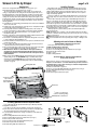
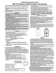
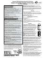
Connecting Controls to Data Cable Splitter Board
Controls plug into the Data Cable Splitter Board, which is located on
the Top Frame on the front side of the lift, using RJ14 connectors.
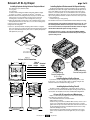
DETAIL OF DATA CABLE
SPLITTER BOARD
Pin
123456
YGRB
Pin
123456
YGRB
Please Note:
Data cable connections must be made using
electrically straight 4-conductor modular cable
(RJ14). If making your own cables, this means
colors do not cross over: blue leads to blue, green
to green, etc. (see diagram below).
LVT
RP/RQ
KEY
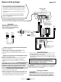
Any control, including automated dry contact systems, being
connected to the wall switch input MUST send a momentary signal.
Pin
123456
YGRB
WALL
For serial control of "Show" position, use data cable with RJ14
connectors on both ends and an R2D7 Serial Control Interface.
Plug into the "RP/RQ" input.
RP/RQ
Function Indicator
For IR or RF Remote Control, use data cable with RJ14 connectors
on both ends.
Low Voltage Trigger
(6-24 VDC)
(No +/- wiring requirement)
RP/RQ Bus Ports for
remote controls such as
IR Eye, RF Receiver, LED
Wall Switch and RS232
LVC-S
Red - Down
Black - Com
Black - Com
Blue - Up
Pin
123456
YGRB
SP-KSM
Green
Black
DCU
Yellow
Low voltage
wiring by others
Green
Black
Yellow
R2D7 (Optional)
Pin
654321
B R GY
CLEARING THE SHOW POSITION AT CURRENT SHOW POSITION:
1 Move lift to the show position.
2 While lift is at the show position press and hold the Key Up toggle
switch and release once the Lift begins moving upward.
3 The show position is now cleared and ready for a new show position
to be set.
CLEARING THE SHOW POSITION AT THE MAINTENANCE POSITION:
1 Move lift to the maintenance position.
2 While lift is at the maintenance position press and hold the Key Down
toggle switch and release once the Lift begins moving upward.
3 The show position is now cleared and ready for a new show position
to be set.
PLEASE NOTE: At this point the Key Switch will not operate until
the new “Show Position” has been set. Also the 3-Button Wall Switch
changes into a maintain, push and hold type button, for continuous
movement. This allows for easy setting of new “Show Position”)
PROCEDURE FOR SETTING SHOW POSITION:
1 Now that the show position has been cleared, use wall switch up and down
buttons to get lift into desired show position.
2 While lift is at desired show position, press and hold the Key Down toggle
switch until lift begins to move upward. Lift will begin a calibration cycle
where it will move upward for two seconds, stop then move down for one
second and then the Lift will return to the desired show position.
www.draperinc.com
Pin
123456
YGRB
To RS232 Port:
Yellow = Rx (Data from control system)
Green = Tx (Data to control system)
Red = Unused
Black = Gnd (Signal Ground)
Optional Delay Feature
1When the Optional Delay Feature is installed the Delay Switch must be in the "Delay On" position for normal operation.
2If the Optional Delay Feature is installed and the "Show Position" requires adjusting, then the "Delay Switch" must be switched to OFF while adjusting the show position.
PLEASE NOTE: If the Scissor Lift loses power, the DOWN
function will not work until you operate the lift in the UP
direction using the wall switch. This allows the lift's control
encoder to recognize it's "home" location.
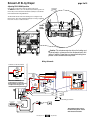
CAUTION: Be sure all switches are in OFF position before adjusting limit
switch. Always be prepared to shut lift off manually when new adjustment is
being tested. Please refer to wiring diagram.
Adjusting Limit Switches
PLEASE NOTE:
Changing the fully open or fully closed position will reset the
electronic controls and cuase the lift to operate improperly.
Please call Draper before attempting these adjustments.
(765) 987-7999