1
Scissor Lift SL by Draper
page 5 of 5
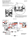
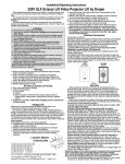
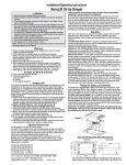
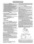
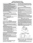
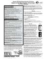
Adjusting FULLY DOWN position
Limit switches for the Scissor Lift SL are preset at the factory.
The DOWN limit switch is set for the fully down (maintenance) position for
the size lift you have ordered. The limit switch assembly is located inside
the lift and behind the Lifting Cable Drum.
DOWN
The Down limit switche shown in the drawing are for setting the "Fully
Down" position. This can be adjusted manually by loosening or tightening
the screw to increase or reduce the travel.
ROTATE
TO
ADJUST
DOWN
Limit
Switch
Caution: The maintenance/service factory limit setting must
not be adjusted to a lower position than the preset factory limit
setting. In addition, Draper does not recommend setting show
position at the maintenance/service position.
Wiring Schematic
ALTERNATE ‘UP’ LIMIT SWITCH WIRING
NC
OR
NC
BK
BK
BK
WH
OR
RD
2 Cond. Cable
Down
Limit
BN Switch
BK
BK
Jumper*
NC RD
NOTE: This CANNOT be
used when lift is installed in
Environmental Air Space Housing
and Optional Ceiling Closure
UCD
BN
RD
WH
BK
YL
YL/GN
Up
Limit
RD Switch
NC OR
BK
NC BK
Delay Switch
(on position)
OR
BK
RD
Run Cap
45 MFD
BK
RD Motor
Down
BK
BK
BK
WH
OR
RD
BL
AC
Up
YL/GN
AC
COM
BK
BK
WH
RD
N.O.
N.C.
OR
BK
Optional Delay Assembly
115V ac, 7A 60 Hz Outlet WH
RD
Attached to lower pan
WH
BK
WH
BK
GN
N
115V ac,
Supply
Up
Limit
RD Switch
WH
FRONT OF DATA CABLE
SPLITTER BOARD
BACK OF DATA CABLE
SPLITTER BOARD
Dashed wiring by electrician
WH
RD
Encoder
KEY
WALL
LVT
RP/RQ
RP/RQ
BK
RD
BK WH
RD
WH
*Black (BK) Jumper wire is
located in the plastic sleeve
with these instructions.
www.draperinc.com
(765) 987-7999