1
@
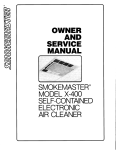
OWNER
AND
TEGHNICAL
MANUAL
SMOKEMASTER'
MODEL
C-12
SELF-CONT\INED
ELEOTRONIC
AIRCLEANER
TABLEOF CONTENTS
SECTION
PAGE
OWNERM
S A N U A LP A R TI
INTRODUCTION
2
COMPONENTS
3
PRINCIPLES
OF OPERATION. .
3
OPERATING
INSTRUCTIONS.
4
MAINTENANCE
4
T E C H N I C AMLA N U A LP A R TI I
SPECTFTCATTONS
G E N E R AILN F O R M A T I O N
Application
......6
....6
.......6
OutdoorAir...
.........7
Sizing.
....7
INSTALLATION
.......8
Location
.........8
C e i l i nMgo u n t i n g
........9
W a lMl o u n t i n g . . . .
......9
Wiring.
....9
CHECKOUT
....10
SERVICE
.......11
ELECTRICAL
TROUBLESHOOT
..
. . . ..12
DTAGNOSTTC
CHECKS
. . . . .13
PARTSLIST.
. . .15
GUIDESPECIFICATIONS
. . ..16
CERTIFICATE
.
OF WARRANTY.
MADEWITHPRIDEIN THE U.S.A.
. . . . . . .17
OWNER
MANUAL
SMOKEMASTER
FART1
Your Smokemaster Electronic Air Cleaner is an advanced sel{-contained electronic air cleaner. The Model C-I2 is
an e{ficient indoor pollution lighter while reducing costly energy consumption.
CLEANAIR
A clean lresh atmosphere is a plus to any business. With yqur new Smokemaster Electronic Air Cleaner, your
customers and employees can now breathe air that is relatively lree ol smoke, dust or pollen. This is especially important with regard to today's concetn with the eflects of smokers upon non-smokers and also lor a more comlortable environment lor allergy sufferers.
LOWERENERGYCONSUMPTION
A common solution to the problem ol dense concentrations ol smoke is to exhaust. Excessive exhausting is wastelul
and very expensive. One is exhausting expensively heated or cooled air and needing to heat and cool the outdoor
ait
coming in. A Smokemaster C-12 drastically reduces the need lor outside air. This ..un. you can save as much as 40
percent on heating and cooling bills!
REDECORATING
Smoke particles also have a tendency to settle out as a dulling lilm on mirrors, windows, trophies, bottles
and
glassware. In lact, most ol the particles which produce soiling attd "taittitrg are
lust too small io be removed by
average dusting. Electronic air cleaning gets rid ol these particles belore they have a chance to start the soiling process. Less soiling means longer periods between redecorating. If the appearance ol your business is important to you,
electronic air cleaning is certainly a plus.
EXTRACOMFORTAND SAVINGS
The ellective air pattern of the Model C{2 creates a more comlortable almosphere by constant slight air
movement. This slight movement, while more comfortable, also helps to eliminate existing drafts: Another side Lenelit
oI the air recirculation pattern is that it distributes the heated or cooled air more evenly. TLi..rr"r, distribution helps
to
reduce the amount of heated or cooled air needed lor the same degree ol warmih oi cool.
LOW OPERATINGCOST
In addition to reduced heating-cooling bills and redecorating bills, the relatively low cost oI maintaining
an electronic air cleaner is another linancial boost to your business. This air cleaner has no throwaway lilter or oiher parts
that must be periodically replaced. The durable electronic cells and prefilter screens are washei and used oiei and
over again. No replacement parts means reduced maintenance cost.
2
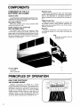
COMPONENTS
OF THE C.l2
COMPONENTS
AIR CLEANER
ELECTRONIC
Cabinet& Grllle
Iow prolile design and finish options assure decor compatibility while also made oI durable steel. Intake grille
adds to the compatible appearance.
RemovablePrefilters
Metal mesh prelilters catch larger particles belore
entering the electronic cells.
System Indicator Lamp, Power Pack
and Three Speed Control
The System Lamp monitors the electrical output
automatically indicating any system mallunciion. The
power supply is located behind the bolted door with the
system indicator light. The three-speed control is accessible and is convenient to alter fan speed lor varying concentrations ol contaminanrs.
Electronic
Cells
Heovy Duty Cells remove eqsily with crttoche grip
handles. Lightweight (972 lbs.) and durable, each cell Iits
easily in the dishwasher or conventional container to
remove trapped particles accumulated {rom cleaning dirty air.
Hlnged Access Door
Allows easy access to components {or periodic cell
and prelilter cleaning. Sa{ety interlock discharges all
power when door is opened. Built-in test button assures
collector perlormance.
Mounting
Mounts on wall brackets or with steel suspension rods.
For mounting directly to a ioist ceiling, lag screws are
available.
..'il:;l
]irliill]ill
For Your Safety
U.L.Listed
(60Hz.unitsonly)
OF OPERATION
PRINCIPLES
HOW YOURELECTRONIC
AIR CLEANERWORKS
Airborne contaminants are trapped by a process
"Electrostatic Precipitation." The diagram below
called
simplilies the construction ol the Smokemaster Electronic
Air Cleaner. Particles are lirst given a strong electrical
charge in the charging section ol each cell. These
charged particles are then attracted to and held by the
collection seclion ol each cell and held there until
cleansed at regular intervals. The Smokemaster C-12 has
its own lan which circulates the air through the unit.
3
Plug
Plugs into any regular l2O volt
grounded outlet.
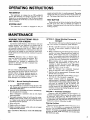
OPERATING
INSTRUCTIONS
FAN SWITCH
Your electronic air cleaner has an OII-low-Med-Hi
switch. The electronic air cleaner and built-in Ian are
designed to run simultaneously. Turn OII the air cleaner
belore opening the access door to remove the electronic
cells lor cleaning.
SYSTEMLIGHT
Your electronic air cleaner is equipped to tell you
simply and quickly that it is working properly. The amber
system light tells at a glance the status ol the power supply. The system light should be on when the unit is on.
TESTBUTTON
Pushing the red test button located on the cell door (on
the side ol the unit), tells you whether the collector is
working. A snapping sound indicates that the collector is
working properly.
MAINTENANCE
WASHINGTHE ELECTRONIC
CELLS
AND PREFILTER
SCREENS
To maintain peak efliciency, the electronic cells and
prelilter screens in your electronic air cleaner must be
washed regularly. The washing is necessary to remove
dirt particles collected Irom the air. Check with your
Smokemaster representative to determine how olten your
cells need to be washed lor your particulat application.
Intake grille may be removed lrom machine {or periodic
washing.
WARNING: Electronic cell is a delicate instrument'and should be handled accordingly. Warranty covers manulacturer's delects only.
Smokemaster Inc. assumes no responsibility lor
misused or damaged cells due to improper handling or maintenance.
CAUTION:
Use care when handling the electronic cells. The
metal edges can be sharp. Also be carelul not to
damage cells by dropping, bumping against lurniture, etc. Do not splash detergent solution in
eyes, and avoid prolonged contact with skin.
Keep detergent out ol children's reach.
OPTION 1 - Manual Washing/Smokemaster
Liquid Cell Cteaner
1. Pour CLEANERinto a containernearly the size of the
cell. Cleanerand containersare available from your
SMOKEMASTERdealer.
2. Immerse cell in CLEANERand remove immediately.
Set cell asidefor 5-7minutes.
Note: If detergent is allowed to dry on cell, repeat
aboveprocedure.
3 . Thoroughlypressure rinse cell with very hot water.
Rinsingis most critical. If cell is not completelyrinsed,
or if water is not very hot, cell will not be clean and
proceduremust be repeated,
4 . Allow cell to dry.
5 . Replacecell in air cleaner.
6 . Replace cleaning solution when cells are no longer
being effectivelycleaned.
CELL CLEANERIS REUSABLE.SAVE FOR REPEATED
USE.
OPTION 2 - Manual Washing/Commercial
Detergent
The electronic cell may be washed manually by soak.
ing it in a solution o{ commercial grade detergent.
l. Provide a suitable container, Iarge enough to hold
the cells. A large plastic dishpan or laundry tub
works well.
2. Select a commercial grade detergent that dissolves
readily in hot water. Depending on local water conditions, some brands may lorm a precipitate or
scum. II a noticeable scum lloats to the sur{ace, try
another brand. Special electronic cell detergent is
available lrom your Srnokemaster representative.
3. Belore placing cells in wash container, pour in
detergent. Use approximalely 3/ecup per cell i{
container is about the size ol cells. Use proportionately more if container is larger. Add enough
very hot water to cover the cells.
4. Alter the detergent has completely dissolved,
place the electronic cells in the container.
5. Soak the cells lor approximately 30 minutes, slosh
several times and remove.
6. Rinse the cells well with very hot water. It is important that all ol the detergent is rinsed olf.
7. Inspect collector plates lor cleanliness. Repeat
wash procedure il necessary. Check the electronic
cells for broken wires and bent collector plates. The
cells may be installed in the air cleaner and
energized. The indicator light may remain oll dur_
ing the normal two hour drying time. However, il
annoying arcing occurs during this period, the cell
may be removed to dry.
OPTION 3 - Automatic Dishwasher
Electronic cells and prelilters can be washed in ar
automatic dishwasher. Make sure that the airllow artows
on electronic cells point up. Also be carelul not to
damage cells by bending plates or breaking ionizer wires
on dishwasher rack. Ttre cells rnay require more {requent
washing il automatic dishwasher is used.
Cleaning prefilters
Remove lint lrom prelilter screens with vacuum
or
wash in a dishwasher or commercial
detergent
solution. Do not wash screens in Smokemaster
cell
cleaner. II ecreens are washed i" ""."a ""rirmercial
solution ae cells, make sure they are wasied
alter
the electronic cells.
4
TEGHNICAL
MANUAL
SMOKEMASTER
FART2
5
THE C-12 IS A SELF-CONTAINEDELECTRONIC AIR CLEANER FOR USE IN
COMMERCIAL AND LIGHT INDUSTRIAL
APPLICATIONS. THE AIR CLEANER IS
MOUNTED IN THE ROOM OR AREA
WHERE THE AIR IS TO BE CLEANED. A.
THREE.SPEED FAN CIRCULATES AIR
THROUGH A METAL MESH PREFILTER
AND AN ELECTRONIC CELL. IT RE'
MOVES AIRBORNE PARTICLESSUCH AS
DUST, SOOT, POLLEN, AND TOBACCO
SMOKE FROM THE AIR.
power supply output is not
r Self-regulating
affected by moderate fluctuations in line
voltage.
I Three-speedlon ctculcrtes up to 1250cubic
leet per minute (2124M3t ).
I Electronic cells easily removedfor cleaning.
r Interlock switchespreventoperationwhen
accessdoor is open.
r 120V, 60 Hz or 220/240V,50 Hz models
availabte.
I powered from a standard grounded electrical outlet.
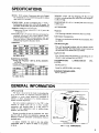
SPECIFICATIONS
MODEL: C-l 2 includes 2 electronic cells and a S-speed
fan. Dischargesair in four directions parallel to ceiling
upon which it is mounted.
WEIGHT: 79 lbs. [36 kg] shipping, 69 lbs. [3] kg]
installed,including electronic cells.Each cell weighs il / 2 l b s . I a . 3k e ] .
POWER CORD: lO Ieet (3 meters) long, 3 wires 3-prong plug included with lzOV 60 I-Iz models. On
22O|2NV,5O tlz models, plug must be purchased locally.
D I M E N S I O N S : 2 5 x 2 5 x I I i n c h e s[ 6 3 5 m m x 6 3 5 m m
x 279.5mml.
AMBIENT TEMPERATURE RATING:
Shipping and Storage minus 40 to 150 F
[minus ulO
to plus65.5 C I
EFFICIENCY:Up to 94 percent elliciency is deivered as
measured according to the national Bureau ol Stan_
dards Dust Spot Method using atmospheric dust, and
American Society o{ Heatirrg, Relrigerating, and AirConditioning Engineers Standard S2-76.
CAPACITY:
FAN
ACCESSORIES:
WashKit
Cell Washing conrainerwith cover.part no. 30182
Cell CleanerConcentrete
Dilutes 4 to one. Stores in abovewash container.part
no.45008
Wrll Mounting Kit
Two wall mounting brackets with air cleaner mounring bolts attached.One blank plate covers louvers on
the wall sideof air cleaner.part no.02006.
Lag Screw Kit
aAt 230V,50Hz.
ELECTRICALRATINGS:
Voltageand Frequency-120Vac,60 Hz;220/240V
ac,50 Hz.
Currentand Porrycr
Consumption-
Four 8 inch screwsand washersfor mounting of air
cleanerto joist ceilings.Part no.05053.
UNDERWRITERS
LISTED:
LABORATORIES
INC.
F i l e N o . E 5 5 7 1I
Guide No. AGGZ (60 Hz. unirs only)
CAI.IADIAN STAIIDAIDS LI9IED,
FiIeNo. LR894l6-l
aAt 230V, 50 Hz.
GENERAL
INFORMATION
APPLICATION
The gl2 is mountedin the roomor areawherethe
air is to be cleaned.It is especiallysuited for servicein
buildings or rooms where existing air circulation is
limited, or where installationof a central system air
cleanerwould be impractical.
One very common applicationfor the C12 is the
removal of smoke from the air in bars, lounges,
restaurants,and bowling alleys. It is also used in a
variety of other applications such as welding shops,
kitctrens,and club rooms.
Becauseit providesits own air circulation, the Clz
may be used in almost any application requiring the
removal of airborne particulate contaminationfrom an
enclosedspace.
It cannot, however, be used in any area where
combustible gasesor vapors are likely to be present
in the air.
FrG. 1- C12 COMPONENTS.
6
- Continued
GENERALINFORMATION
MAKE.UPAIR
Recommendedquantitiesof clean outdoor ventilation air for variousapplicationsare described in
Table 2 of the ASHME Standard 62-89'Ventilation
for AcceptableIndoor Air Quality.' ASHRAE
(AmericanSociety of Heating,Refrigerating,and
Air ConditioningEngineers,Inc., Phone #404-63684OO)notes that these recommended outdoor air
quantitiesmay be reduced by the use of clean,
recirculatedair if the IAQ Procedure6.2 is used
Appendix E of ASHME 62-89 includes recommendationsfor the use of clean recirculatedair'
However,in most cases, adequate controlof carbon dioxide generallyrequiresa minimum clean
orrtdoorair quantityof no less than 15 cubic feet
of air per minute Per Person.
Additionalventilationmay be requiredfor toxic contaminants. In any event,the air cleaner must be
used only in areas which are ventilatedfor human
occupancy in order to disipate any incidentalgeneration of ozone,
SIZING
Electronicair cleanersare generallybestsized
accordingto the useof the areaandthe volumeof
the room(AirChangesper HourMethod).
Secondaryfactorsto considerin applyingelectronicair cleanersinclude:
-typeof contamination
-numberof occupants
-olrtsideairquality
-anticipated
fan setting
-rateof contaminate
generation
thesefactors,the numberof air
By considering
can be adjustedup or downto
required
cleaners
in operatingconditions.
accountfor abnormalities
FollowSteps1 through4 to determinethe number
of aircleanersrequired:
Steo1 - Measurethe length,width,and height
of the roomin feet.
the Air Changesper Hour
Step2 Determine
required.SeeChartA below.
the C.F.M.(CubicFeetper
Steo3 - Determine
Minuteof Aifl. SeeChartB below.
Steo4 - Plugthe figuresfromSteps1-3intothe
sizingformulabelowand calculatethe
numberof air cleanersrequired.
7
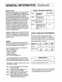
CHARTA - AIR CHANGESPER HOUR
Load
of
Description.
Application
Light
Generaloffices&
computer rooms
Air Changes
4-5
6
Average Conferenceand
break rooms
Heavy
Designatedsmoking
areas,bingo halls,
bars, & elitra smoky
areas
8-10
CHARTB. CUBICFEETOF AIR PER MINUTE
fan motor.
Theaircleanerhasa three-speed
to
Usethe C.F.M.thatcorresponds the speed
thatthe aircleanerwilloperateon normally.Low
speedwherenoiseis a primeconcernand high
speedwherenoiseis not a factor.
Hlgh
Model C-12
Low
Medium
c.F.M.
800
1050
1zso
Nolse Level
57.5
dB(A)
65
dB(A)
69
dB(A)
SIZINGFORMUI.A
L x W x H of Roomx AirChanges/ Hr.
: # ol C-12's
C.F.M.of Air (seeChartB) X 60 Min.
for cellcleaning
interval
NOTE:Themaintenance
the numberof
can be lengthenedby increasing
air cleanersbeyondthe requirednumber.
INSTALLATION
l. Installer must be a trained, experienced
serviceman.
2. Disconnect power supply before installation
to prevent electrical shock and eguipment
damage.
- L . *E*
a
-f*
_T_
-T
3. All wiring must comply with applicablecodes
and ordinances.
t
+l
4. Do not exceed the ratings given in the
SPECIFICATIONSsection.
c.rz f+
t'
5. Always conduct a thorough checkout when
installationis complete.
LOCATION
The C 12 should be mounted on th€ Giling near the
center of the room. Air is drawn into the bottom of
the C-12 and dischargedin 4 directions. Divide larger
rooms into sections and use an C-12 in the crnter of
eachsection(Fig. 2).
F I G . 2 - M O U N T T H E C . 1 2 O N T H E C E I L I N GA T
THE CENTER OF THE AREA TO BE
CLEANED.
Check the existing air circulation in the room. The
C-12 should be installed so that it aids the sirculation
already $tablished. When airflow patterns are not
immediately apparant, obserw the snpke froma cigarette
in various locations within the room.
1 u r . rr1r j
rf
TheC-]2 should be installed at the c€iling in nearly
all applications. This is especially important when the
air cleansr is used for smoke crntrol. Visible smoke
contains very small particles-so srnall, in fact, tbat
they are not noticaably affected by gravity. Smoke
lsrrelly risesto the ceiling and hangsthere.
r o P o Fc . r 2
,
If the C-12 must b€ installed some distanor away
from ths ctiling, make sura it is at least 14 inches
[355 mm] away from the ciling. This measureis necessary to reduce staining of th€ $iling of lingring srnoky
air. When the air cl€aner is right against the ceiling, the
air at the ceiling is moving too fast to deposit dirt
particlss. Ovtr 14 inchc [355 mm] from the cuiling,
ths effsct is not a probhm. But in thc spaoebotsrern,
rlow moving, dirty air is drawn into thc aroa of ths
dircharg outbts and can stain a light colorod c.iling.
-o-| //
l
A
/tla
llal
CLEARANCE
HoLz(.t
-o I
l
eluow rr uelsr rr rNcxEst3goMMI FoR cELL REMovAL.
FIG.3-APPROXIMATE INSTALLATION DIMEN.
stoNs tN tNcHEs (MtLLtMETERStN
BRACKETS.
8
CEILING MOUNTING
The C-I2 ir mounted by supending it from the
csiling.
The mounting holes in the C- I 2 ore spoced 16 inches
(406.5 mm) between centers in both directions. This
mqkes it eqsy to fosten the oir clecrner directly to the
ceiling tomework with 8 inch log screws. Lecrve spqce
tor the power cord to run between the top ol C-12 qnd
ceiling. The power supply cord must not be concecrled
crbove ceilings or behind wqlls.
Notc in Fig. 4 that the air cleaner is not srspended
from the top but rathsr from the venturi plate, which
is heavier rnatd and desiEred to supPort the entire
dcvicc.
oRrLL l/ll lN. llMMl
PILOT HOLES
LEAVE SPACE
FOR CORO
!/. IN. II9 MMI OIAMETER
CLEANANC€ IiOLES
IN AIR
PROVTD€O
C L E A N E RH O U S I N G
3 / 6X t r N . l r 0x 2 0 3 M M l L AS
GC R E w
A N DW A S H E(RA C C E S S I EWL IET H
REMOVEO)
FITTER
A N OC E L L S
OR VENTURI
O O N O T O V E R T I C H T E NL A G S C R E W S
P L A T EM A Y O I S T O R T .
FIG. 4-USE FOUR 3/8 X 8 INCH LAG SCREWSAND
WASHERSTO FASTENTHE C.12 TO THE CEILING FRATE.
Be surethat you select a strong structural part oI the ceiling. Do not fasten it to a lalse ceiling or to plaster or plasterboard. In somecases,it may be necessaryto conskuct soure
type o{ framing strong enough to support the weight ol the
c-rz.
Thc C-12 rnayalsobemountcdrdngs/8in'[l0nnJ
diamatertbr€ded stoel rods availablcin nuny hardwaro
stor€s.Four st€€lrds wiu be rcquird.
WALL MOUNTING
Tvro wall mounting brackets are utd to support thg
C-12. Ttrey are included in an acctssory pa*agc along
with a blank plate to block off the outlet louvlrs on
the side of ths air cleaner which will be aginrt thc
wall.
The 2 brackets must be rnountd on the wdl 16
inches [406.5 mm] between cantors so thet th€ long
bolts will line up with the air cleaner mounting holes.
The brackets should be sccurely fastened to the wall
studs with lag screws. On rnasonry walb, u88appropriate
scr8wanchors.
Use the blank rnetal plate to block off the louvered
outlet on the side of tha air cleaner thet wiU face the
wall. Use the 2 screws with nuts and washes to fasten
this plate to the louwrs.
EOLT ANO WASHER
WALL BRACXE' (2}
BLANK PLATE
MOUNT AS CLOSE
TO CEILING
AsFossrELE
l-
,
NUT
,'/
\
NUT ANO WASHER
TOP ANO BOTTOM
'7
NUT AND WASH€R
TO? ANO BOTTOM
/,/
[-
-- ?i3
l;i,'i
LAG SCREW
SRACK€TS TO
not oua"trcHTEN LAGscR€wsoR vENlrJRtP.-ATEMAYolsroRt'
TIOUITTINGBRACKETS
FIG. 6-USE ACCESSORY
TO MOUNTC.12ON WALL.
OIAMETER
THREAOEO ROD
t.r/2 rN. lla0 MMI
THREADEO
ROD B€LOW
CEILING
I
I
NUI ANO WAs}tER
TOP ANO 3O?IOM
DO NOT OVERTIGHTEN LAG 5CREWSOR VENIURI
PLATE MAY OISYORT.
STEEL
FIG.s-}IANGTHEG12FBOiITHETHREADED
RODSWHICHBOLTTOTHEVENTURIPLATE.
I
WIRING
The 120V, 60 llzOl2lras a standaldS'pronEplugon
a I0 foot [3 m] powercord.It requiresonly a standard
groundd outlet for eleetricalPower.O'nthe 22O|24OV,
SO fU models,add a S'prongplug (purchasedlocally)
to the pow€rcord.
Ttre power sourcemust be 120 volt, @ Hz ot 22Ol
240V,50 Hz dependingon mdel.
Route the power cod 30 that it will be out of the
wayof the building'soccuPants.
PERMANENTWIRING
To permanently wire the C-12 follow these instructions
exactly. All wlring must comply with applicable codes and
ordinances. Wire the C-12 using the built-in iunction box
as indicated in lig.7 The power source must be l2O volt,
60 Hz.
It is recommended that No. 14 or heavier wire be used to
complete the wiring from the junction box to the external
power source. However, be sure to comply with local codes.
ii\
l. Open C-12 junction box cover (Fig.7).
2. Disconnect and discard the power cord, the
solderless connectors and strain relief. PIug the
power cord hole with the plug provided.
SO! D€ RLLSS
!O\llfCTORS
3. Run conduit lrom power supply to junction box
through the appropriate knockout. Fish wires to
iunction box.
4 . Connect Iead wires with solderless connectors
including ground (green) wires. Proper grounding
ol this device is mandatory lor correct operation
and salety.
5. Insert hole plug in hole where power cord
was removed.
F I G . 7 - R E M O V ET H E J U N C T I O N B O X C O V E R T O
GAIN ACCESS TO THE POWER SUPPLY
CONNECTIONS.
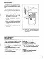
CHECKOUT
Before leaving the installation, check to be sure that
the Ol2 is properly installed and operatescorrectly.
MOUNTING
o The Cl2 is securely fastened to the ceiling or wall'
6 lt is mounted wher€ it will not interfere with normal
occupant traffic.
tr Unit is properly oriented for good air circulation.
ASSEMBLY
O Elestronic cells are cor€stly orientd-airflow
pointing toward blower.
El hefilter screGnsproporly instalhd.
arrows
OPERATION
O Fan runs correctly in all speedsettings.
o SYSTEM light turns on when fan is running.
O Opening acoess door stop6 fan and turns out the
systemlight.
NOTE: If the Ctz does not apPear to work right,
refer to ELECTRICAL TROUBLESHOOTING'
CLEANUP
tr Clean the outside surfac€sof the air cleaner.
CJ Oean up the installation area.
10
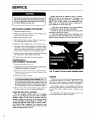
SERVICE
The lollowing instructions are intended lor qualiIied service personnel only. Dangerotrs line voltage
circuits are o<posed during this procedure. Disconneci power before servicing unit.
MOTORREPLACEMENT
PROCEDURE
L Disconnect power {rom unit.
2. Open cell access door. Remove cells, pre{ilters, and
grille to provide access to motor.
3. Remove lan blade lrom motor.
Broken wires must be replaed as roon ar possible.
Remove all parts of the broken wire. lf neoessary.the
cell may be temporarily used with I wire mrsring. See
PARTS LIST for part number of the replacem.nr wlne
Wires come cut to length with eyeletsat eachcnd for
easyinstallationin the electroniccell.
I. Use care to avoid damageto the spring connestor
or other partsof the cell during the installation.
2. Hook one end of the ionizing wire over the spring
connectorat one end of the cell.
3. Hold the oppositeeyelet with a needlenosepliers
and stretch the wire the length of the cell. Depressthe
opposite spring connector and hook the eyelet over it.
Disconnect lan motor leads at disconnect near motor
(or at terminal block on earlier units).
5 . Remove 4 screws holdinq motor and bracket to unit.
6 . On earlier units it will be necessary to install a bracket
(included in motor replacement kit) in place ol the
cable clamp. Plug the electrical connector into this
bracket and route the wires to the terminal block.
Install new motor and bracket, connect electrical lines
and replace lan, grille, prelilters and cells.
8. Connect power and check new motor operation.
POWERSUPPLY
REPLACEMENT
PROGEDURE
f . Disconnect power lrom unit.
2. Dlsconnect quick connect terminols tom power supply,
Unplug power supply wte hqmess.
3. Remove 4 screws holdinq power supply in place.
(On earlier units, remove nuts and washers {rom
inside ol cabinets.)
4. Install new power supply
5. Connect line voltage wires to power supply with
plugrs, Wlres wlth dtnll@ colors go togetber. Ned, connect the pink highvoltqgew"bes to the oubide terminols
on the contqct boqrd which qre mqrked L Attqch the
grey high voltoge wires to the irside termincls morked
C. Be cerloin that oll wires cse connected properly.
6. Reconnect power and test power supply with test
button to be sure unit is operating properly.
W I R ER E P L A C E M E N T
IONIZING
The fine tungsten ionizing wires in the charging
section of the electronic cell may break or become
damaged. Inspea the cell from the upstream side after
washing to make sure that none of the wires are broken
or out of position. During operation, a broken or deformed wire generally causesa short to ground, possibly
with visible arcing or sparking. This condition, or any
other short in the ionizing section of the cell, will
causethe indicator light to go out.
11
FIG. 8.!NSTALLATIONOF NEWIONIZINGWIRES.
ARCING
From time to time you may hear a snapping noise coming lrom the electronic air cleaner. This arcing occurs
when the air cieaner collects an unusually large particle,
when cells are wet, extraordinarily dirty or damaged.
If an unusual amount ol arcing persists, check lirst to
determine if the electronic cells need washing. look also
Ior any sign ol bent collector plates or broken ionizer
wlres.
II arcing siill occurs when cell is clean and dry, consult your serviceman or dealer lor repair.
PROCEDURE
MOTORMAINTENANCE
The manufacturer of the motor used in the C-12
necommendsoiling of the motor at least once a year.
The followingprocedurecan be followed:
o De-energizethe unit.
. Removethe prefilters and cells from the cabinet.
. Removethe fan blade from the motor shaft.*
. Unscrew the four screws holding the motor mounting
plate, and lower the motor. THE WIRING NEEDNOT
BE DISCONNECTED.
r There are lwo oil holeson the motor:
1. Near the motorshaft.
2. On the end opposite the motor shaft near the
bearingplate.
o Five drops of SAE 20 weiSht nondetergent oil or
electric motor oil in eachhole is adequate.
. Wipe off excess oil which misses or runs out of oil
holes.
r Replacemotor fan blade, cells and pre-filters in the
unit.
. Re€nergize and check out to ensure proper operation'
*Fan blade need not be removed if serviceman has a
hypodermic-typeneedle available for insertion of oil
throughoil hole plug. 1 cc is approximatelyfive drops.
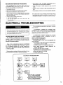
TROUBLESHOOTING
ELECTRICAL
The troubleshooting procedi.rredescription is divide,l
into 2 sections:
The lollowing instructions are intended {or qualified service personnel only. Dangerous line voltage
circuits are exposedduring this procedure.Disconnect power before servicing unit.
T R O U B L E S H O ONTGI P R O C E D UER
The following troubleshootingproc€dure has been
designedto speedthe serviceman'swork and insure that
any rnalfunction in the'electronicair cleaneris quickly
detectedand properly repaired.
Most of the troubleshooting steps can be performed
by observing the indicator light. This light is powered
by the resonating winding on the high voluge transformer and is ON wheneverthe high voltagetransformer
is working properly.
This procedureis outlined in the llow chart below.A complete descriptionis provided on the lollowing pages'
1. DIAGNOSTIC CHECKS-The numbered stePs
correspondto the numberedstepson the uoubleshooting
flow chart. Follow this sequenceof checksto locatethe
causeof a failure within the air cleaner.
2. COMPONENT CHECKS-Explains how to Iocate
a faulty component within an assembly,or how to
provea comPonentgood or bad.
TOOLSAND EOUIPMENT
Troubleshooting the Cl2 can be accomplishedwith
only a few tools.
o Screwdrivers-long shank, plasticor rubber handles;
2 required for somearc checks.
o Needlenosepliers-for stringing ionizing wires.
o Test Meter-Honeywell W859 Electronic Air
CleanerTest Meter,or
o Simpson260 with 25 kV dc Probe.
o Solderingiron for replacingcomponents.
o Neon test lamp for line voltage.
. A sparesilicon diode.
E T E C T R I C A LT R O U B L E S H O O T I T U G
OPEFAIION
LIGHI o|
+
cT-----]
I :*s* l----J
l**' I
I rNcoRR€cr
(Y TOGROUND)
IONIZER
VOLTAGE
DCMINIMUM.
NOCELLS-8,5(X)V
wrTH cELLS-7,500TO 8,500vDc.
VOLTAGE
{R TO GROUND}
COLLECTOR
DCMINIMUM.
NOCELLS-3,sOOV
DCMINIMUM.
WITHCELLS-3,OOOV
12
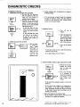
DIAGNOSTIC
CHECKS
DIAGNOSTICCHECKS
1. ENERGIZE ELECTRONICAIR CLEANER
a. Be sure that the electronic
cells and prefilter screensare
clean, dry, and properly installed in the air cleaner.
b. Energize the air cleaner and
check for operation in all fan
speeds.In each case the fan
NO FAN
OPERATION
should run and the SYSTEM
light shouldturn on.
-If the fan does not run,
check the fan motor, power
sourc€,and interlock safety
switch.
-lf the SYSTEM light does
not come on, go to step 3.
-If the fan runs and the
SYSTEM light comes on,
go to step 2.
b. Arcing indicates that the electronic air cleaneris
working properly.
c. If no arcing noise is heard, check for cgntinuity
through the collector resistor, and then check for
a failure in the electronic ceUs, voltage doubler
circuit, or cell contact boards.
3. REMOVECELLS
a. Turn pff
' cleaner.
b. Open the acrcess
door
by removing 2
thumbscrewsholding
door in place. Re.
move the electronic
cells.Closethe door.
2. CHECKCOLLECTOR
OUTPTIT
,n.o"*..r$[1'rX;1-l
----tlnX*:n.ncurr
I
volrAGE wrR|NG I
t-l
a. With air cleaner turned on,
push
TEST
BUTTON to
momentarily
short out the
collector section of the
electronic cell.
the air
+i#r-)
c. Turn the air cleaner
oN.
-If the light comeson now, check the electronic
cellsfor a short circuit.
-If the light rernainsoff, go to step 4.
4. CHECKPOWERSUPPLYAND INDICATORLAMP
a. Removethe 4 screws
holding the control
door in place and
open the door.
VOLTAGT
b. Usea neon test light
or a voltmeter to
checkline voltageon
the primary of the
high voltage transformer.
-If the correct line voltageis present,continue the
checkout.
-If the correct line voltage is not measuredon
the primary of the high roltage transformer,
check backwards through the switch and wiring.
to the power sourc€ until the problem can be
located and corrected.
c. Checkthe voltageon the indicator light.
-If the voltageis correct (about l20V ac) and if
the light is out, replacethe assembly.
13
-ll there is no voltoge, or Iess thon IOOV qc, the
power supply musl be reploced. See poge I I
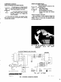
COMFONENT
CHECKS
SOURCE
CHECKFANMOTORANDPOIVER
lf the fan doesnot run whentheswitch
is in HIGH,MEDIUMand LOWpositiom,
checkvoltagesuppliedto the motor.
I. If the morordoesnot turn with the
correctvoltageapplied,checkto seethat
the shaft is free to turn. Replacr the
motor if necdsary.
!o FAi
orfnatroN
I
2. If the correctline voltageis not m€asured,
check
beck throughtho wiring to the powsr source,including
intcrlocksafetyswitches.
CELLS
CHECKELECTRONIC
WSUAL INSPECTION
Carefullyoraminsthe electroniccells.
Look especidlyfor€LECTRONIC I
|
-Bent collectorplat6s.
I cELLr
I
-Brokon ionizingwiras.
r_-|
-Dirt accumulation
on insulators.
I
-Contact tabs-ionizer and colloctor
b'nn"
I
damage.
l-..*. I
CHECK FOR SHORT CIRCUITS
Use an ohmmotcr to check resistancebetween the
outsido frama of the cell and both the ionizer and
cgllector contasts. In each cas€, the resistancl should
be infinite (open circuit).
FIG. ll-USE AN OHMMETERTO CHECKTHE
ELECTRONIC CELLS FOR SHORT
clRculTs.
C-I2 ELECTRONIC AIR CLEANER
..PIN
HICH VOLTACE
POWER SUIPLY
PLUC
C RE Y
..PIN PLUC
:
I
GROUND
r x r en r - o c xs a F E r Y
swrrcrl
smorEmgsTEB'
INPUT
t20v
aoHz
HICH SPEED
MEDIUM SPEED
LOW SIEED
t-3A
2.1A
2-14
1t0 wATTs
230WATTS
2aewaTTs
6. gi(^! ,
OUTPUTT2.ln^ AT ll50 vDC
6D ,.o,,.,u.,
LrsrEo
ELEcrRosrArc
3895
AIR CLEANER
REV (.
I U AD E I N U . S . A
51021
V
FIG. 12 INTERNALSCHEMATICDIAGRAM
14
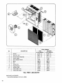
I
2
3
4
5
_q
_
7
8
I
10
11
PARTNUMBER
120V.
2201240V.
60 HZ MODELS 50 HZ MODELS
41009 (2)
4 1 0 0 9( 2 )
38001 (2\
38001 Q\
4 6 1 1 3( 2 )
4 6 1 1 3( 2 )
07089
07071
10106
10106
DESCRIPTION
NO.
Prefilter
ElectronicCell
Contact Board Assembly
PowerSupply
Door InterlockSwitch
05013
37022
Fan
_
Power Cord
_7
Control Switch
_I
lndicator Light
I
4rorl
louo-loor?
f-
,0016
a ,oor5
Intake Grille, lvory
Intake Grille, Black
TOLL FREE1-800-328-0787
PARTSNOTILLUSTRATED
of 5),PartNo.38004
lonizingWires(package
15
05014
g?on
w
I
1 0 1 0t
10097
|
20026
w
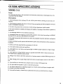
GUIDE SPECIFICATIONS
MODELC.I2
Scope:
The following describesa self-contained,cord-connected,electronic
air cleaning device to be
suspendedfrom the ceiling.
Description:
1' Unit shall operate from ordinary 120 volt,50 Hz. power source,
drawing no more than 3.3
amPeres.
2'.unit shall be equipp-edwith power cord and three prong plug
and also equipped to be hard
wired in installation if desired.
3' Provision for ground wire connectionin field wiring compartment
shall be made.
4' Fan motot shall be of shaded pole design and capableof running
at three distinct speeds:hi,
med and lo.
5. Air dischargeshall be in four different directions.
5' Atmospheric dust spot efficiency shall be 89o/ominimumwhen
tested according to ASHRAE
Standard 52-76,and up to 93Voeff-icienton lo speed.
7.' Unit-shall incorporate bell-mouthedfan orifice for purposes
of quieter operation and greater
throughput.
8' Built in interlock switch system shall disconnect power from all
functions when accessdoor
is opened.
9. Airflow on Hi fan speed shall be a minimum of 1250
cfm.
10. Unit shall include metal mesh prefilters.
11' Unit shall have a test button and system light to indicate
proper operation of high voltage
power system.
12' Unit shall have voltage doubler system to provide over
8,000 volts to ionizer section and
over 4,000 volts to collectorsectionof cell.
13' Design of air cleanershall limit production of noxious ozone
to within osHA approved levels.
1a' High voltage Power supply design shall limit short circuited
output current to less than 5
mA.
15' Unit shall have a total electroniccell plate area of at least
105.gsquare feet.
16. No tools shall be required to open or closecell accessdoor.
17' Air cleanershall mount to building supports on 16 inch
centersand layout template shall
be included to facilitate mounting.
l8' Unit shall be listed by Underwriters Laboratoriesfor use
as an electrostaticair cleaner.
16
CERTIFICATE
OF WARRANTY
WARRANW
LIMITEDONEYEARSMOKEMASTER
Air Quality Engin€ering, Inc. warrants the Smokemaster Electronic Air Cleaners to be free from delects in worloanship or materials, under normal use and service, Ior a period oI one ( I ) year ftom the date oI purchase by tbe congumer
II, at any time during the warranty period, the product is de{ective or mallunctions, Air Quality Engineering, Inc.
shall repair or replace it (at Air Quality Engineering's option) 1yifhin 6 reasonable period o{ time.
II the product is delective,
(i) return unit or delective component with a bill oI sale or other dated prool oI purchase, to the retailer ftom which
you purchased it, or
(ii) package unit or component, along with prool oI purchase (includiag date purchased) and a short description
oI the mallunction, and mail or ship, postage or fteight prepaid, to the lollowing addrees:
AIR OUALITY ENGINEERING, lNC. Customer Service 7140 Northland Drive North. Mnpls., MN 55428-1520
The repa.ired or replaceo part or unit will be shipped bV Air Quality Engineering, Inc. to the puchasea freight collect,
with the purchaser to be responsible lor all freight charges. The warranty on any repaired or replacement part shall
be lor a duration oI tine no longer than the remaining or unexpired term oI the original warranty. This warranty does
not cover any labor or other service charges incurred by the purchaeer.
This warranty shall not apply iI it is shown by Air Quality Engineering that the delect or mallunction was caus€d
by damage which occurred while product was in the poesession ol a consumer.
Air Quality Engineering's sole responsibility shall be to repair or replace the product within the terms stated above.
AIn QUALITY ENGINEERING SHALL NOT BE LIABLE FOR ANY CONSEQUENTLAL DAIVIAGES RESUXilNG
FROM ANy BREACH OF WARRANTY, EXPRESS OR IMPLIED, APPIJCABLE TO THIS PRODUCI. Some states
do not allow the exclusion or lirnitation ol conseguential damages, 80 this limitation may not apply to you.
ORIMPUED,AND TIIE WANNANTIES
THISWANruNTYIS IN TJEUOF ALL OTHERWARMNTIES,EKPRESS
OFMERC}TJINTtsILITYANDFITNESSFORAPANTICUUNPURPOSEAREHEREBYEXCLTJDEDBEYOI{DTHE
Somestatesdonotallowlimitationsonhowlonganinplied warranty
ONEYEARDUnef,IONOFTHISWARRANTY.
Iasts, so the above linitation
may not apply to you.
This warranty gives you specific legal rights, and you may also have other rights which vary from state to state.
18
smorEmgsrER'
AIR OUALITY ENGINEERING,INC. 7140 NORTHLAND DRIVE NORTH, BROOKLYN PARK, MN 55428-152O
(8OO)328-O7a7 . FA)( (763) 531-99OO. [email protected] ' www-air-quality-eng.com
c-12s83A PN #51167 REV.A