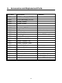
1
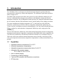
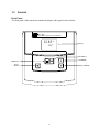
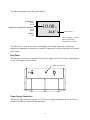
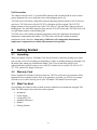
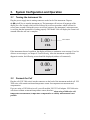
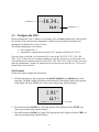
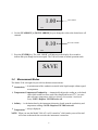
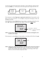
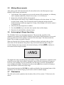
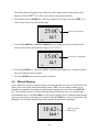
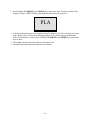
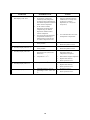
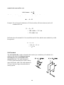
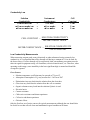
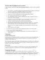
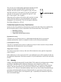
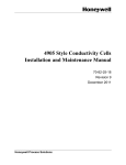
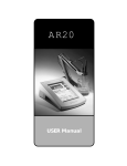
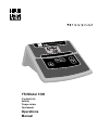
CONDUCTIVITY INSTRUMENT µS C YSI Model 3100 Conductivity Salinity Temperature Instrument Operations Manual Table of Contents 1. Introduction..............................................................................................................................................1 1.1 Capabilities ...................................................................................................................................................... 1 1.2 Controls............................................................................................................................................................ 2 Front Panel...................................................................................................................................................... 2 Rear Panel....................................................................................................................................................... 3 2. Getting Started.........................................................................................................................................4 2.1 Unpacking........................................................................................................................................................ 4 2.2 Warranty Card.................................................................................................................................................. 4 2.3 What You Need ............................................................................................................................................... 4 3. System Configuration and Operation....................................................................................................5 3.1 Turning the Instrument On............................................................................................................................... 5 3.2 Connect the Cell............................................................................................................................................... 5 3.3 Configure the 3100 .......................................................................................................................................... 6 Cell Constant .................................................................................................................................................. 6 3.4 Measurement Modes ........................................................................................................................................ 7 3.5 Making Measurements ..................................................................................................................................... 9 3.6 Autoranging & Range Searching ..................................................................................................................... 9 3.7 Platinization ..................................................................................................................................................... 9 4. Advanced Setup.....................................................................................................................................10 4.1 Cell Calibration.............................................................................................................................................. 10 4.2 Temperature Coefficient ................................................................................................................................ 12 4.3 Reference Temperature .................................................................................................................................. 12 4.4 Manual Ranging............................................................................................................................................. 13 5. Maintenance...........................................................................................................................................15 5.1 Cell Cleaning and Storage.............................................................................................................................. 15 5.2 Platinization ................................................................................................................................................... 15 6. Troubleshooting ....................................................................................................................................17 Error Messages ............................................................................................................................................. 17 7. Principles of Operation .........................................................................................................................19 7.1 3100 Principles .............................................................................................................................................. 19 7.2 Conductivity Principles.................................................................................................................................. 19 Introduction .................................................................................................................................................. 19 Conductivity Fundamentals .......................................................................................................................... 19 Cell Constant ................................................................................................................................................ 20 Choosing a Conductivity Cell ....................................................................................................................... 21 Cell Constant Calculation ............................................................................................................................. 22 Conductivity Cell Calibration - Some Things To Remember ..................................................................... 22 Conductivity Law.......................................................................................................................................... 23 Low Conductivity Measurements ................................................................................................................. 23 General Conductivity Measurement Precautions .......................................................................................... 24 Platinization .................................................................................................................................................. 24 Temperature Correction................................................................................................................................ 24 i Small Sample Measurements ........................................................................................................................ 25 Conductivity System Accuracy Considerations ............................................................................................ 26 7.3 Salinity ........................................................................................................................................................... 26 7.4 Temperature ................................................................................................................................................... 27 7.5 Sources of Errors ........................................................................................................................................... 27 Cell Contamination ....................................................................................................................................... 27 Cell Platinizing ............................................................................................................................................. 27 Electrical-Noise Errors ................................................................................................................................. 27 Contact Resistance........................................................................................................................................ 27 Cable Series Resistance and Shunt Capacitance ........................................................................................... 28 Galvanic and Miscellaneous Effects ............................................................................................................. 28 8. Warranty & Repair .................................................................................................................................29 8.1 Cleaning Instructions ..................................................................................................................................... 30 8.2 Packing Instructions....................................................................................................................................... 31 8.3 Disassembly/Assembly Procedures................................................................................................................ 32 9. Accessories and Replacement Parts...................................................................................................33 9.1 YSI Conductivity Cells .................................................................................................................................. 34 9.2 Standard Calibrator Solutions ........................................................................................................................ 35 10. Required Notice ...................................................................................................................................36 11. Appendix A - Specifications ...............................................................................................................37 12. Appendix B - Temperature Correction Data For Typical Solutions................................................38 13. Appendix C - Conversion Factors......................................................................................................42 14. Appendix D - Glossary of Terms ........................................................................................................43 ii 1. Introduction The YSI Model 3100 is a microprocessor based instrument designed to perform laboratory measurement of conductivity, salinity and temperature. The instrument’s push button operation makes it simple to use. The Model 3100's microprocessor allows the system to be easily calibrated with the press of a few keys. Additionally, the microprocessor performs a self-diagnostic routine each time the instrument is turned on. The self-diagnostic routine provides you with useful information about the cell constant, function of the instrument circuitry, and the quality of the readings you obtain. The system simultaneously displays temperature (in oC), along with one of the following parameters: conductivity (in µS/cm or mS/cm), temperature compensated conductivity, (in µS/cm or mS/cm), and salinity (in parts per thousand [ppt]). You can switch back and forth from salinity, conductivity, and temperature compensated conductivity with a single push of the [MODE] key. The new YSI 3200 series conductivity cells contain internal temperature sensors for temperature measurement and automatic temperature compensation. The Model 3100 is also compatible with YSI 3400 series conductivity cells when used with the YSI Model 3232 cell adapter. However 3400 series cells do not contain an internal temperature sensor, therefore, when using a 3400 series cell, temperature measurement, temperature compensation or salinity measurement is not possible. 1.1 Capabilities • • • • • • • • Adjustable reference temperature 15 to 25 °C Automatic temperature compensation Adjustable temperature compensation factor 0 to 4%/°C Adjustable Cell constant, ranges: 0.01, 0.08-0.12, 0.8-1.2, 8-12 Auto or manual ranging Conductivity or Salinity readings 7-pin mini DIN connector with thermistor connections AC line power 1 1.2 Controls Front Panel The front panel of the instrument contains the display and keypad as shown below. 3100 CONDUCTIVITY INSTRUMENT 12.85 uS 22.4°C Display ENTER Key UP ARROW MODE Key Power ON/OFF DOWN ARROW 2 The following diagram shows the typical display. Conductivity: mS/cm uS/cm Temperature compensated conductivity: mS/cm uS/cm 10.00 µS 24.8 °C Salinity: ppt Temperature: °C NOTE: Flashing °C symbol indicates temperature compensation is enabled. The [Mode] key is used to select the current display mode. Mode choices are conductivity, temperature compensated conductivity or salinity. Temperature is always displayed at the bottom of the screen. Rear Panel The rear panel contains the connections for the power supply and cell. It also has a mounting post for the 3232 adapter as shown below. Adapter mounting post @ 100ma Power Supply Connection The power supply connection requires a 12 VDC power supply (included) with at least 100 ma current. The polarity is marked on the instrument. 3 Cell Connection The connector for the cell is a 7-pin mini DIN connector and is marked with an arrow to show proper alignment. Be sure to align the arrows when plugging in the cell. YSI 3200 series cells utilize a mini DIN connector that plugs directly into the 3100. If, however, you have a YSI 3400 series cell, the YSI 3232 cell adapter will be required. The YSI 3232 adapter mounts on the post on the rear of the 3100. It has a 7-pin mini-DIN connector and two binding posts. The mini-DIN connector plugs into the 3100 cell socket and a YSI 3400 series cell (or equivalent) connects to the binding posts. YSI 3200 series cells contain an internal temperature sensor for temperature measurement, temperature compensation and salinity. YSI 3400 series cells do not contain an internal temperature sensor, therefore, when using a 3400 series cell, temperature measurement, temperature compensation or salinity measurement is not possible. 2. Getting Started 2.1 Unpacking When you unpack your new YSI Model 3100 for the first time, check the packing list to make sure you have received everything you should have. If there is anything missing or damaged, call the dealer from whom you purchased the Model 3100. If you do not know which of our authorized dealers sold the system to you, call YSI Customer Service at 800-765-4974 or 937767-7241, and we'll be happy to help you. 2.2 Warranty Card Please complete the Warranty Card and return it to YSI. This will record your purchase of this instrument in our computer system. Once your purchase is recorded, you will receive prompt, efficient service in the event any part of your YSI Model 3100 should ever need repair. 2.3 What You Need Several things are needed in order to make accurate conductivity measurements using the YSI 3100. The following list shows the basic items required. • • • • • • Instrument Power Supply Conductivity Cell Standard Solution(s) Beakers Rinsing Solution 4 3. System Configuration and Operation 3.1 Turning the Instrument On Plug the power supply into its mating connector on the back of the instrument. Depress the (on/off) key to turn the instrument on. The instrument will activate all segments of the display for a few seconds, which will be followed by a self test procedure which will last for several more seconds. During this power on self test sequence, the instrument’s microprocessor is verifying that the instrument is working properly. The Model 3100 will display the current cell constant when the self test is complete. 1.00 Cell constant CEL If the instrument detected a problem, the display will show a continuous error message. For a list of these error messages, see chapter 6 Troubleshooting. After the instrument completes this diagnostic routine, the following screen should be displayed (with no cell connected). 0.00 µS udr °C 3.2 Connect the Cell Plug the cell (YSI 3200 series) into the connector on the back of the instrument marked cell. YSI 3200 series cells contain an internal temperature sensor for temperature measurement and compensation. If you are using a YSI 3400 series cell, you will need the YSI 3232 cell adapter. YSI 3400 series cells do not contain an internal temperature sensor, therefore, when using a 3400 series cell, temperature measurement, temperature compensation or salinity measurement is not possible. 5 Conductivity 16.34 µS 24.8 °C 3.3 Temperature: °C Configure the 3100 Before operating the 3100, or whenever you change cells, you must configure the 3100 to match the cell used. You must enter the manufacturer’s stated (or your manually calculated) cell constant (K) as shown below (Cell Constant). The default configuration is as follows: • • Cell constant of K = 1 Temperature compensation corrected to 25°C using a coefficient of 1.91%/°C. If you are using a cell with a cell constant of K=1 (such as the YSI 3252, 3253, 3254, 3401, 3403, 3417, or 3445), the cell constant is already set correctly. If, however, you are using a cell with a different cell constant (such as the YSI 3256, 3255, 3402, 3418, 3440, or 3446), you must enter the manufacturer’s stated cell constant for the cell that you are using (K= 0.1, 10.0 etc.) as shown below (Cell Constant). Cell Constant Follow these steps to change the cell constant. 1. With the instrument on, press and release the [DOWN ARROW] and [MODE] keys at the same time. The CAL symbol will appear at the bottom left of the display and the large portion of the display will show 1.91% (or a value set previously using Advanced Setup). 1.91% 22.7 °C Cal symbol CAL 2. Press and release the [MODE] key. The large portion of the display will show 25.0C (or a value set previously using Advanced Setup). 3. Press and release the [MODE] key again. The large portion of the display will show 1.00 (or a value set previously using Advanced Setup). 6 1.00 Cell constant CAL 4. Use the [UP ARROW] or [DOWN ARROW] keys to change the value to the desired new cell constant. 0.10 New cell constant CAL 5. Press the [ENTER] key. The word “SAVE” will flash across the display for a second to indicate that your change has been accepted. The 3100 will return to normal operation mode. SAVE 3.4 Measurement Modes The Model 3100 is designed to provide four distinct measurements: ! Conductivity -- A measurement of the conductive material in the liquid sample without regard to temperature ! Temperature Compensated Conductivity -- Automatically adjusts the reading to a calculated value which would have been read if the sample had been at 25o C (or some other reference temperature which you choose). See section 4. Advanced Setup. NOTE: Requires YSI 3200 series cell. ! Salinity -- A calculation done by the instrument electronics, based upon the conductivity and temperature readings. NOTE: Requires YSI 3200 series cell. ! Temperature -- Always displayed. NOTE: When you turn the Model 3100 off, it will “remember” which mode you used last and will return to that mode the next time the instrument is turned on. 7 To choose one of the measurement modes (temperature is always displayed), simply press and release the [MODE] key. Carefully observe the small legends at the far right side of the LCD. Temperature Compensated Conductivity with °C Conductuctivity with °C Salinity with °C If the instrument is reading Temperature compensated conductivity, the large numbers on the display will be followed by either a µS or mS and the small portion of the display will show the o C flashing on and off. If the instrument is reading Conductivity, the large numbers on the display will be followed by either a µS or mS, but the small portion of the display will show the oC NOT flashing. 10.62 mS 24.8 °C °C Not flashing = Conductivity °C Flashing = Temperature compensated conductivity NOTE: The instrument measures conductivity in uS/cm or mS/cm even though the /cm is not shown on the display. If the instrument is reading Salinity, the large numbers on the display will be followed by a ppt. 34.2 Salinity ppt 24.8 °C NOTE: Temperature compensated conductivity and salinity modes cannot be used unless a YSI 3200 series cell is connected. When using a YSI 3400 series cell (or equivalent) with the 3232 cell adapter, these modes will display an error message (“LErr”) since 3400 series cells do not contain a temperature sensor. 8 3.5 Making Measurements After setting up the 3100 instrument and cell as described earlier, the following basic steps should be used to make measurements. 1. Verify that the 3100 is properly set up to use the current cell by measuring, or calibrating with, a standard conductivity solution. See section 4.1 Cell Calibration. 2. Immerse the cell in the solution to be measured. 3. Gently tap the cell to remove any air bubbles and dip the cell in the solution 2 or 3 times to ensure proper wetting. The cell electrodes must be submerged and the electrode chamber must not contain any trapped air. If using a flow through or fill cell, be certain it is completely full. 4. Allow time for the temperature to stabilize. 5. Press the [MODE] key to select the units required, then read the display. 6. Rinse the cell with distilled or deionized water. 3.6 Autoranging & Range Searching The YSI Model 3100 is an autoranging instrument. This means that, regardless of the conductivity or salinity of the solution (within the specifications of the instrument), all you need to do to get the most accurate reading is to put the cell in the sample. This feature makes the Model 3100 as simple as possible to operate. When you first place the cell into a sample or calibration solution, and again when you first remove the cell, the instrument will go into a range search mode that may take as long as 5 seconds. During some range searches, the instrument display will flash rANG to indicate its movement from one range to another. rANG The length of the range search depends on the number of ranges which must be searched in order to find the correct range for the sample. During the range search, the instrument will appear to freeze on a given reading for a few seconds then, once the range is located, will pinpoint the exact reading on the display. The display may also switch to 00.0 for a second or two during a range search before it selects the proper range. During normal operation, the [ENTER] key enables and disables the autoranging feature of the instrument. See 4.4 Manual Ranging if you need to switch to manual ranging. 3.7 Platinization The 3100 can be used to replatinize the electrodes of the cell. See section 5.2 Platinization for details. 9 4. Advanced Setup For highest accuracy, the 3100 and cell may be calibrated as a system using standard conductivity calibration solutions. See the following section, 4.1 Cell Calibration, for details. The default temperature compensation settings of the YSI Model 3100 are appropriate for the vast majority of measurement applications. However, some measurement applications require very specific measurement criteria. For that reason, we have made the YSI Model 3100 flexible to accommodate these “advanced users.” If, for example, you are using the YSI Model 3100 for a process control application which requires that the conductivity readings be compensated to 20°C instead of 25°C -- see section, 4.3 Reference Temperature. Or, if your application involves the measurement of a very specific saline solution, the default temperature coefficient may need to be changed to get the very best measurement of that specific salt. See section 4.2 Temperature Coefficient. 4.1 Cell Calibration Prior to calibration of the YSI Model 3100, it is important to remember the following: • The cell constant must be set correctly before calibrating. See section 3.3 Configure the 3100, Cell Constant. • Always use clean, properly stored, NIST traceable calibration solutions (see section 9.2 Standard Calibrator Solutions). When filling a calibration container prior to performing the calibration procedures, make certain that the level of calibrant buffers is high enough in the container to cover the electrodes. Gently agitate the cell to remove any bubbles in the conductivity cell. • Rinse the cell with distilled water (and wipe dry) between changes of calibration solutions. • During calibration, allow the cell time to stabilize with regard to temperature (approximately 60 seconds) before proceeding with the calibration process. The readings after calibration are only as good as the calibration itself. • Perform calibration at a temperature as close to 25°C as possible. This will minimize any temperature compensation error. Follow these steps to perform an accurate calibration of the YSI Model 3100: 1. Select a calibration solution which is most similar to the sample you will be measuring. • • • For sea water choose a 50mS/cm conductivity standard (YSI 3165 or 3169) For fresh water choose a 1mS/cm conductivity standard (YSI 3161 or 3167) For brackish water choose a 10mS/cm conductivity standard (YSI 3163 or 3168) 2. Place at least 3 inches of solution in a clean glass beaker. 3. Insert the cell into the beaker deep enough to completely cover the electrodes. Do not rest the cell on the bottom of the container -- suspend it above the bottom at least 1/4 inch. 10 4. Gently tap the cell to remove any air bubbles and dip the cell in the solution 2 or 3 times to ensure proper wetting. If using a flow through or fill cell, be certain it is completely full. 5. Allow at least 60 seconds for the temperature reading to become stable. 6. Press the [MODE] key until the instrument is in the conductivity mode that you want to calibrate in as follows: Temperature compensated conductivity (°C symbol flashing): This mode will automatically compensate the calibration value to 25°C using a coefficient of 1.91%/°C. Conductivity (°C symbol NOT flashing): This mode does NOT use temperature compensation. 7. Press and release both the [UP ARROW] and [DOWN ARROW] keys at the same time. 10.12 mS 24.3 °C CAL CAL symbol The CAL symbol will appear at the bottom left of the display to indicate that the instrument is now in Calibration mode. 8. Use the [UP ARROW] or [DOWN ARROW] key to adjust the reading on the display until it matches the value of the calibration solution you are using. If you are calibrating in temperature compensated conductivity mode, enter the value at 25°C. If you are calibrating in conductivity mode (not temperature compensated), enter the value the calibration solution should read at the current temperature (see Appendix B). 10.00 Calibration solution value mS 24.3 °C CAL 9. Once the display reads the exact value of the calibration solution being used, press the [ENTER] key. The word “SAVE” will flash across the display for a second indicating that the calibration has been accepted. The YSI Model 3100 is designed to retain its last calibration permanently. Therefore, there is no need to calibrate the instrument after power down. 11 4.2 Temperature Coefficient Follow these steps to modify the temperature coefficient of the Model 3100. 1. Press and release the [DOWN ARROW] and [MODE] keys at the same time. The CAL symbol will appear at the bottom left of the display and the large portion of the display will % show 1.91 (or a value set previously using Advanced Setup). 1.91% Temperature coefficient 22.7 °C CAL CAL symbol 2. Use the [UP ARROW] or [DOWN ARROW] key to change the value to the desired new temperature coefficient. 1.50% New temperature coefficient 22.7 °C CAL 3. Press the [ENTER] key. The word “SAVE” will flash across the display for a second to indicate that your change has been accepted. 4. Press the [MODE] key two times to return to normal operation; the CAL symbol will disappear from the display. See Appendix B for charts of common salt solutions at various temperatures. 4.3 Reference Temperature Follow these steps to modify the reference temperature of the Model 3100. 1. Press and release the [DOWN ARROW] and [MODE] keys at the same time. 1.91% 22.7 °C CAL symbol CAL 12 The CAL symbol will appear at the bottom left of the display and the large portion of the % display will show 1.91 (or a value set previously using Advanced Setup). 2. Press and release the [MODE] key. The large portion of the display will show 25.0C (or a value set previously using Advanced Setup). 25.0C Reference temperature 22.7 CAL 3. Use the [UP ARROW] or [DOWN ARROW] key to change the value to the desired new reference temperature (the allowable range is 15°C to 25°C). 15.0C New reference temperature 22.7 CAL 4. Press the [ENTER] key. The word “SAVE” will flash on the display for a second to indicate that your change has been accepted. 5. Press the [MODE] key to return to normal operation. 4.4 Manual Ranging If your application is easier to perform using a manual range that you select, the YSI Model 3100 allows you to turn off the default autoranging feature. While you are making conductivity or temperature compensated conductivity measurements, simply press and release the [ENTER] key. The conductivity units will flash indicating that the instrument is now in a manual range. Each additional press of the [ENTER] key will cycle the Model 3100 to a different manual range until you return again to autoranging. Six pushes of the [ENTER] key will cycle the Model 3100 through the five available manual ranges and return the instrument to autoranging. 10.62 mS 24.8 °C 13 Flashes to indicate Manual range NOTE: You may see an error message in some manual ranges if the range selected is not adequate for the sample you are measuring. rErr mS Range error message 24.8 °C If this happens, simply press and release the [ENTER] key again until a range is selected which is suitable for your sample. If you get lost and don’t know if you’re in a manual range or autoranging, simply turn the instrument off and back on. The instrument will default to autoranging when first turned on. The YSI Model 3100 has five possible ranges. The number of ranges available for use depends on the current cell constant. Cell Constant Range 1 0 - 49.99 µS/cm Range 2 0 - 499.9 µS/cm K=0.01 √ √ K=0.1 √ √ √ K=1 √ √ √ √ √ √ √ K=10 Range 3 0 - 4999 µS/cm Range 4 0 - 49.99 mS/cm Range 5 0 - 499.9 mS/cm √ NOTE: Cells may be used beyond their normal range, but with instability and/or reduced accuracy. 14 5. Maintenance 5.1 Cell Cleaning and Storage The single most important requirement for accurate and reproducible results in conductivity measurement is a clean cell. A dirty cell will change the conductivity of a solution by contaminating it. To clean a conductivity cell: 1. Dip or fill the cell with cleaning solution and agitate for two to three minutes. Any one of the foaming acid tile cleaners, such as Dow Chemical Bathroom Cleaner, will clean the cell adequately. When a stronger cleaning preparation is required, use a solution of 1:1 isopropyl alcohol and 10N HCl or Sulfuric Acid or Ethanol or Methanol. CAUTION: Cells should not be cleaned in aqua regia or in any solution known to etch platinum or gold. 2. Remove the cell from the solution and rinse in several changes of distilled or deionized water. Inspect the platinum black to see if replatinizing is required. Storage Short term: Store conductivity cells in deionized or distilled water. Change the water frequently to prevent any growth that may cause electrode fouling. Long term: Rinse thoroughly with deionized or distilled water and store dry. Any cell that has been stored dry should be soaked in distilled water until the electrodes appear black before use. 5.2 Platinization The electrodes of YSI 3200 and 3400 Series conductivity cells are coated with platinum black during manufacturing. This coating is extremely important to cell operation, especially in solutions of high conductivity. The cell should be inspected periodically. If the coating appears to be thin or if it is flaking off, the electrodes should be cleaned, as noted above, and replatinized. Properly maintained conductivity cells will perform for years without replatinizing. The 3100 can be used to replatinize the electrodes of the cell. In addition, you will need a 2-oz bottle of platinizing solution (YSI 3140). WARNING: Before replatinizing the electrodes of a cell, make sure that the cell is designed to have a platinum coating on the electrodes. 1. Immerse the cell in the platinizing solution (YSI 3140). Make sure that both electrodes are submerged. 15 2. Press both the [UP ARROW] and [MODE] keys at the same time. The large portion of the display will show “PLA” flashing, indicating that platinization is in process. PLA 3. After the platinization process is complete (about 30 minutes), the 3100 will return to normal mode. Remove the cell from the platinizing solution. If you want to stop the platinization before 30 minutes have passed, press both the [UP ARROW] and [MODE] keys at the same time to abort. 4. Thoroughly rinse the cell with distilled or deionized water. 5. Promptly return the platinizing solution to its container. 16 6. Troubleshooting Error Messages The instrument performs a Power On Self Test each time it is turned on. The following error messages are provided to facilitate troubleshooting. They appear on the LCD when an error is detected. SYMPTOM 1. Instrument will not turn on 2. Instrument will not calibrate 3. 4. 5. 6. 7. Instrument readings are inaccurate Main Display reads “OVEr” Main Display reads “Undr” Main Display reads “rErr” Main Display reads “PErr” POSSIBLE CAUSE ACTION • • Power supply Instrument requires service • • Check power supply and AC outlet Return system for service • Incorrect calibration procedure • See 4.1 Cell Calibration • Cell needs cleaning • See 5. Maintenance • Instrument requires service • Return system for service • Calibration is required • See 4.1 Cell Calibration • Cell is contaminated • See 5. Maintenance • Temperature coefficient has been set incorrectly • See 4.2 Temperature Coefficient • Reference temperature incorrect • See 4.3 Reference Temperature • Readings are or are not temperature compensated. • See 3.4 Measurement Modes • Conductivity Reading is over range: >112 uS with K=0.01 cell >11.2 mS with K=0.1 cell >112 mS with K=1 cell >499.9 mS with K=10 cell • In all cases, check calibration values and procedure; check Advanced Setup settings. • Set cell constant to correct range. See 3.3 Configure the 3200, Cell Constant. • If each of these is set correctly, return system for service. • Set cell constant to correct range. See 3.3 Configure the 3200, Cell Constant. • Recalibrate using known good conductivity standard. See 4.1 Cell Calibration. • Follow cell cleaning procedure. See 5. Maintenance. • Use the ENTER key to select a higher or lower manual range, or to set system to Autoranging. • Refer to manual section which provides step by step procedures for the function you are attempting. • Salinity reading is > 80ppt • User cell constant cal is over the limit of the current range • User cell constant cal is under the limit of the current range • User has selected manual ranging & sample exceeds selected range • Conductivity reading is over the range of the instrument: >499.9 mS • Incorrect sequence of key strokes 17 SYMPTOM 8. 9. Main Display reads “LErr” Secondary Display reads “Err ra” 10. Secondary Display reads “Err ro” 11. Secondary Display reads “udr” 12. Secondary Display reads “ovr” 13. Secondary Display reads “rEr” POSSIBLE CAUSE ACTION • Adjust user defined temperature coefficient (see 4.2 Temperature Coefficient) or reference temperature (see 4.3 Reference Temperature) • Use a YSI 3200 series cell or turn off temperature compensation. System has failed its RAM test check procedure • Turn instrument OFF and back ON. • Return the system for service. System has failed its ROM test check procedure • Turn instrument OFF and back ON. • Return the system for service. • Current cell does not contain a temperature sensor (such as YSI 3400 series). • Use a YSI 3200 series cell if temperature readings or compensation are required • Temperature is < -5o C • Read solution of higher temperature • Replace Cell/Cable assy • In temperature compensated conductivity mode, temperature exceeds the values computed using user defined temperature coefficient and/or reference temperature. • In cell constant cal mode, temperature exceeds the values computed using user defined temperature coefficient and/or reference temperature. • The user has selected Temperature Compensated Conductivity or Salinity and the current cell does not contain a temperature sensor. • • • • Temperature is > 95o C o Temperature jumper is set to F and reading is >199.9 o F but < 203 o F 18 • Return system for service • Read solution of lower temperature • Replace Cell/Cable assy. • Return system for service • Set jumper to read o C. • Return system for service 7. Principles of Operation 7.1 3100 Principles The YSI 3100 obtains a conductance value by varying the amplitude of a square-wave current forced through the cell so that the center-sampled magnitude of the cell voltage for each halfcycle is constant and is equal to a reference voltage. In this condition, the current and conductance are directly proportional. To convert this conductance value to conductivity, it is multiplied by the cell constant which has units of reciprocal cm (cm-1). For most applications, the cell constant is automatically determined (or confirmed) with each deployment of the system when the calibration procedure is followed. Solutions with conductivities of 1.00, 10.0, 50.0, and 100.0 mS/cm, which have been prepared in accordance with recommendation 56-1981 of the Organization International De Metrologie Legale (OIML) are available from YSI. The instrument output is in µS/cm or mS/cm for both conductivity and temperature compensated conductivity. The multiplication of cell constant times conductance is carried out automatically by the software. 7.2 Conductivity Principles Introduction Conductivity measurements are used in waste water treatment, industry, pharmaceutical, and military etc. as a measurement of the purity or the condition of a process. Conductivity is used as a measurement of a solution’s ability to conduct electric current. The ability of a solution to conduct electric current depends upon ions: their concentration, size, mobility, viscosity, valence and the temperature of the solution. Inorganic solutions are relatively good conductors. Organic solutions are poor conductors. Conductivity Fundamentals Electrical conductance (k) is defined as the ratio of the current (I) in a conductor to the difference in the electrical potential (V) between its ends (k=I/V), measured in mhos or siemens (S). Conductance, therefore, is not a specific measurement. Its value is dependent upon the length of the conductor. Conductivity (ℵ ℵ), or specific conductance, is the conductance per unit of conductor length. For our purposes, conductivity is defined as the conductance in mhos or siemens measured across the sides of a one centimeter cube of liquid at a specified temperature. Looking at our electrodes as sides of a cube, it becomes apparent that the conductance changes as the geometry of the cube changes. If the cube lengthens with respect to the area of the sides, then the conductance will decrease. If the area of the sides increases with respect to the distance between them, then the conductance will increase. The conductivity, however, will remain the same, regardless of the geometry, provided that the temperature and composition of the measured solution remain constant. A factor called the cell constant (K) relates conductivity to conductance. The cell constant is defined as the ratio of the distance between the electrodes (d) to the area 19 normal to the current flow (A): d Cell Constant = K = A Therefore, conductivity equals conductance multiplied by the cell constant. ℵ = k ×K Example: For an observed conductance of 100 micro mhos (100 microsiemens) and a cell constant of 0.1/cm ℵ = k × K = 100 µ mho × 0.1 / cm = 10 µ mho / cm In SI units, the cell constant K=0.1/cm would become K=10/m, and the same conductivity would be expressed: ℵ = k × K = 100 µ S × 10 / m = 1 mS / m Cell Constant The cell constant (K) is used to determine the resistivity or conductivity of a solution. It is defined as the ratio of the distance between electrodes (d) to the area normal to the current flow (A). Cells with constants of 1.0/cm or greater normally have small, widelyspaced electrodes, while cells with constants or 0.1/cm or less have larger electrodes that are closely-spaced. 20 Choosing a Conductivity Cell Decide which cell will be the most useful for your conditions by considering the conductivity of the solution you want to measure, the size of the sample and if temperature measurement or compensation is required. 3252, 3417 3418 3256, 3402 3255, 3446 3401 3440 3253, 3403 3254, 3445 0 0.1 1.0 10 1000 µS/cm 1 100 10 100 1000 mS/cm Conductivity The chart above reflects general guidelines. Refer to cell specifications for details. 3200 SERIES CONDUCTIVITY CELLS Dip cells are generally used for routine conductivity measurements. The 3254 Fill Cell is designed for small sample or high throughput work. It requires only 5 ml of sample and can make measurements quickly from one sample to the next. The 3255 Flow Cell is designed for in-line conductivity measurements, such as for ultrapure water systems. For temperature measurement, temperature compensation or salinity, use YSI 3200 series cells. 3252 3253 3254 3255 3256 21 Cell Constant Calculation YSI 3200 and 3400 Series conductivity cells are calibrated to ± 1% of nominal by means of a YSI transfer standard traceable to OIML Recommendation 56 and NIST. Anytime the condition of the conductivity cell changes, it is possible that the cell constant has also changed. Therefore, you should calibrate your system regularly. If you want to manually calculate your cell constant, measure the conductance of a standard solution and compare with the theoretical conductivity of the solution. The formula for determining the cell constant is: K = where K k ℵ ℵ k = cell constant in cgs metric units (cm-1) = measured conductance in µ mho = theoretical conductivity in µ mho/cm The measured conductance (k) and conductivity (ℵ) must either be determined at the same temperature or corrected to the same temperature for the equation to be valid. One main reason for cell constant calibration is to increase overall system accuracy. Conductivity Cell Calibration - Some Things To Remember 1. Rinse the cell and solution container with some calibrator solution before calibration. 2. Prevent contamination of the solution. 3. Minimize evaporation of the solution. 4. Use adequate sample volume. 5. Purge all air from the cell. 6. Allow adequate time for temperature equilibration. 7. Stir the solution slowly. 8. Know the solution temperature accurately; a 1º C temperature error is approximately a 2% error in conductivity. 9. Insure sound electrical connection between the cell and the instrument. 22 Conductivity Law Solution Conductivity S/cm or mho/cm mS/cm or mmho/cm µS/cm or µmho/cm Instrument Conductance S or mho mS or mmho µS or µmho = = = CELL CONSTANT = × × × Cell Constant 1/cm 1/cm 1/cm SOLUTION CONDUCTIVITY METER CONDUCTANCE METER CONDUCTANCE = SOLUTION CONDUCTIVITY CELL CONSTANT Low Conductivity Measurements When measuring reagent grade water (deionized) or other substances having extremely low conductivity, it is recommend that a flow-through cell having a constant of 0.1/cm be used for the best accuracy. If a flow-through cell is not practical, then extraordinary precautions must be taken in regard to equipment setup, cell cleanliness, electrical interferences, etc. Therefore, when operating on this range, some instability in the least significant digit is normal and should be averaged or ignored. Error Sources • • Solution temperature coefficient may be upwards of 7% per °C Absorption of atmospheric CO2 may account for 1.3µS/cm at 25°C • • • • • • • • Platinization ions may leach into the solution from the electrodes Glass ions may leach into the solution from the cell or container Organic substances may leach into the solution if plastic is used Electrical noise Contact resistance Cable series resistance and shunt capacitance Cell series and shunt capacitance Galvanic effects Only the first four are of major concern for typical measurements, although the user should also be careful to see that cells are clean and maintained in good condition at all times. 23 General Conductivity Measurement Precautions After selecting the proper cell, observe the following precautions to ensure accurate, repeatable results: 1. The cell must be clean before making any measurements. When working with substances having low conductivity, extraordinary cleanliness may be required. 2. Soak cells that have been stored dry in deionized water before use. 3. Immerse the cell in the solution deep enough to submerge the vent hole. 4. The electrode chamber should be free of trapped air. 5. The cell should be at least ¼ inch away from any other object, including the walls or bottom of the solution container. 6. Stirring may be necessary for highest accuracy measurements, especially in lowconductivity solutions and to achieve good thermal equilibration. 7. If possible, isolate from ground potential the measurement container. 8. Electrical fields and stray currents caused by stirrer motors, heaters, etc., can interfere with measurements. The user should determine the effects of these and make the necessary corrections, either by shielding or by disconnecting those units that cause trouble. 9. Always handle the cell carefully. 10. Always rinse the cell carefully before transferring it from one solution to another. 11. Never store a dirty or contaminated cell. 12. The cells should not be submerged in aqua regia or any solution which might etch or dissolve gold. Platinization Platinum Black Inspection The electrodes of YSI 3200 and 3400 Series conductivity cells are coated with platinum black during manufacturing. This coating is extremely important to cell operation, especially in solutions of high conductivity. The cell should be inspected periodically. If the coating appears to be thin or if it is flaking off, the electrodes should be cleaned and replatinized. Properly maintained conductivity cells will perform for years without replatinizing. Replatinizing The 3100 can be used to replatinize a cell that utilizes electrodes coated with platinum. See section 5.2 Platinization. You will need a 2-oz bottle of platinizing solution (YSI 3140). Temperature Correction By convention, the conductivity of a solution is the conductivity it exhibits at 25°C. The conductivity of electrolytic solutions varies with temperature, concentration, and composition. The amount that the conductivity changes with temperature is expressed as a percent 24 change in conductivity for each degree change in temperature (%/°°C), which is called the temperature coefficient. In extreme cases, the temperature coefficient may have a value as high as 7%/°C. Each conductive ion has a different temperature coefficient. When practical, control the temperature of the solution to be analyzed. For high precision work (±1%), maintain the temperature at 25°C ± 0.1°C. For routine lab work, 25°C ± 0.5°C may be acceptable. (Ref: ASTM D1125-82 Standard Methods of Test for Electrical Conductivity of Water) When sample temperature control is not practical, use temperature correction to determine the conductivity at 25°C. The temperature coefficient of your sample can be determined either from published data or from measurements of representative samples. This coefficient may then be applied to correct future measurements on samples of similar composition. If sample composition changes appreciably, the coefficient should be redetermined. Once the temperature coefficient is known, the conductivity at 25°C can be manually determined from the following equation: ℵ25 = where T ℵ25 ℵT α ℵT 1 + α (T - 25) = temperature of sample = conductivity at 25°°C = conductivity at measurement temperature T = temperature coefficient of the conductivity solution Determining The Temperature Coefficient You can determine the linear temperature correction coefficient of a solution by measuring its conductivity at different temperatures using the following equation: α= where T ℵ25 ℵT α ℵT - ℵ25 ℵ25 (T - 25) = temperature of sample = conductivity at 25°°C = conductivity at measurement temperature T = temperature coefficient of the conductivity solution Small Sample Measurements It is not always possible to immerse the conductivity cell in a solution for measurements. If the quantity of solution is not sufficient for a proper measurement with a dip cell, a sample must be removed for assay. For this application, use the 3254 fill cell. This cell requires 5 mL of sample. Alternatively, any 3200 or 3400 Series cell, except the 3418 or 3440, may be inverted and used as a fill cell. 25 The cell you use for small sample applications depends upon the quantity of solution available and the conductivity of the solution. The 3401 cell (K=1.0/cm) requires 15 mL, the 3256 and 3402 cells (K=0.1/cm) require 12 mL, the 3253 and 3403 cells (K=1.0/cm) require 3 mL, and the 3252 and 3417 cells (K=1.0/cm) require 1 mL of sample. When a dip cell is used as a fill cell, the cell's vent hole is sealed and the electrode chamber is inverted and filled with solution, changing the cell constant (K). The cell will require calibration after being configured as a fill cell. Conductivity System Accuracy Considerations System accuracy for conductivity measurements is equal to the sum of the errors contributed by the environment and the various components of the measurement setup. These include: • • • Instrument accuracy Cell-constant accuracy Temperature measurement accuracy Instrument Accuracy YSI meters are very accurate; however, each instrument and range has its own accuracy statement and therefore, must be accounted for in the overall accuracy determination. Cell-Constant Accuracy YSI cells are warranted to be accurate to within one percent, for more accurate work you should calibrate the cell to determine the exact cell constant. Temperature Accuracy The solution temperature accuracy is the sum of the instrument accuracy plus the temperature sensor accuracy. If the conductivity is to be expressed at 25°C, some additional errors will be introduced either by the instrument's temperature correction electronics or by the mathematics used for the conversion to 25°C. 7.3 Salinity Salinity is determined automatically from the Model 3100 conductivity and temperature readings according to algorithms found in Standard Methods for the Examination of Water and Wastewater (ed. 1995). The use of the Practical Salinity Scale 1978 results in values which are unitless, since the measurements are carried out in reference to the conductivity of standard seawater at 15°C. However, the unitless salinity values are very close to those determined by the previously-used method where the mass of dissolved salts in a given mass of water (parts per thousand) was reported. Hence, the designation "ppt" is reported by the instrument to provide a more conventional output. 26 7.4 Temperature The Model 3100 system utilizes a thermistor of sintered metallic oxide which changes predictably in resistance with temperature variation. The algorithm for conversion of resistance to temperature is built-in to the Model 3100 software, and accurate temperature readings in degrees Celsius or Fahrenheit are provided automatically. No calibration or maintenance of the temperature sensor is required. 7.5 Sources of Errors Cell Contamination This error is usually due to contamination of the cell by some previous solution. Normally this is in the form of an organic film which reduces the solution-electrode interface conductance. Follow the cleaning instructions carefully. An entirely different form of contamination sometimes occurs when cells are stored for long periods of time wet; alga and other life forms grow on the electrodes. While rare, such deposits have, on occasion, markedly reduced the effectiveness of the cell by reducing the solutionelectrode interface conductance. Cell Platinizing Errors can be introduced by cells that have begun to lose their electrode coating of platinum black when measuring solutions having high conductivity values. The effect of poor platinization is a loss of linearity and a noticeably large change in conductance from range to range on the instrument. When you suspect a problem with the cell platinization, follow the instructions for electrode inspection and replatinization carefully before attempting any critical measurements. Electrical-Noise Errors Electrical noise can be a problem in any measurement range, but will contribute the most error and be the most difficult to eliminate when using the lowest conductance settings. The noise may be either line-conducted or radiated or both, and may require revised lead dress, grounding, shielding, or all three. Often, all that is necessary is to make sure that parallel leads are of equal length and twisted together. Contact Resistance YSI 3200 series cells utilize a 4-wire connection virtually eliminating errors due to contact resistance. When using the YSI 3232 cell adapter to connect a 2-wire cell (such as the YSI 3400 series cells), contact resistance can be a source of error when measuring high conductivity. Lugs should be clean and free of mechanical distortion. They should fit squarely on terminal posts that are properly tightened. Leads should also be inspected to verify that no physical damage has occurred that might degrade electrical contact. 27 Cable Series Resistance and Shunt Capacitance YSI 3200 series cells utilize a 4-wire connection virtually eliminating errors due to cable resistance. The short cables provided as a part of regular cell assemblies will introduce negligible error in most measurements. However, if longer cables are required or if extraordinary accuracy is necessary, special precautions may be prudent. When using the YSI 3232 cell adapter and a 2-wire cell (such as the YSI 3400 series cells) with solutions having very high conductivity values, a high cable resistance will become a major source of error unless accounted for. When working with solutions having very low conductivity values and long cables with large capacitance, such as might be used with a flow-through cells at remote locations, the large cable capacitance will become a major source of error. Galvanic and Miscellaneous Effects In addition to the error sources described above, there is another class of contributors that can be ignored for all but the most meticulous of laboratory measurements. These errors are always small and are generally completely masked by the error budget for cell-constant calibration, instrument accuracy, etc. Examples range from parasitic reactances associated with the solution container and its proximity to external objects to the minor galvanic effects resulting from oxide formation or deposition on electrodes. Only trial and error in the actual measurement environment can be suggested as an approach to reduce such errors. If the reading does not change as the setup is adjusted, errors due to such factors can be considered too small to see. 28 8. Warranty & Repair YSI Model 3100 Instruments are warranted for two years from date of purchase by the end user against defects in materials and workmanship. YSI cells and cables are warranted for one year from date of purchase by the end user against defects in material and workmanship. Within the warranty period, YSI will repair or replace, at its sole discretion, free of charge, any product that YSI determines to be covered by this warranty. To exercise this warranty, write or call your local YSI representative, or contact YSI Customer Service in Yellow Springs, Ohio. Send the product and proof of purchase, transportation prepaid, to the Authorized Service Center selected by YSI. Repair or replacement will be made and the product returned, transportation prepaid. Repaired or replaced products are warranted for the balance of the original warranty period, or at least 90 days from date of repair or replacement. Limitation of Warranty This Warranty does not apply to any YSI product damage or failure caused by (i) failure to install, operate or use the product in accordance with YSI’s written instructions, (ii) abuse or misuse of the product, (iii) failure to maintain the product in accordance with YSI’s written instructions or standard industry procedure, (iv) any improper repairs to the product, (v) use by you of defective or improper components or parts in servicing or repairing the product, or (vi) modification of the product in any way not expressly authorized by YSI. THIS WARRANTY IS IN LIEU OF ALL OTHER WARRANTIES, EXPRESSED OR IMPLIED, INCLUDING ANY WARRANTY OF MERCHANTABILITY OR FITNESS FOR A PARTICULAR PURPOSE. YSI’s LIABILITY UNDER THIS WARRANTY IS LIMITED TO REPAIR OR REPLACEMENT OF THE PRODUCT, AND THIS SHALL BE YOUR SOLE AND EXCLUSIVE REMEDY FOR ANY DEFECTIVE PRODUCT COVERED BY THIS WARRANTY. IN NO EVENT SHALL YSI BE LIABLE FOR ANY SPECIAL, INDIRECT, INCIDENTAL OR CONSEQUENTIAL DAMAGES RESULTING FROM ANY DEFECTIVE PRODUCT COVERED BY THIS WARRANTY. YSI Authorized Service Centers Please contact YSI for the nearest authorized service center. YSI Technical Support • 1725 Brannum Lane • Yellow Springs, OH • 45387 • Phone: +1 937 767-7241 • 800 897-4151 (US) [email protected] • www.ysi.com 29 8.1 Cleaning Instructions NOTE: Before they can be serviced, equipment exposed to biological, radioactive, or toxic materials must be cleaned and disinfected. Biological contamination is presumed for any instrument, probe, or other device that has been used with body fluids or tissues, or with waste water. Radioactive contamination is presumed for any instrument, probe or other device that has been used near any radioactive source. If an instrument, probe, or other part is returned or presented for service without a Cleaning Certificate, and if in our opinion it represents a potential biological or radioactive hazard, our service personnel reserve the right to withhold service until appropriate cleaning, decontamination, and certification has been completed. We will contact the sender for instructions as to the disposition of the equipment. Disposition costs will be the responsibility of the sender. When service is required, either at the user's facility or at YSI, the following steps must be taken to insure the safety of our service personnel. 1. In a manner appropriate to each device, decontaminate all exposed surfaces, including any containers. 70% isopropyl alcohol or a solution of 1/4 cup bleach to 1 gallon tap water are suitable for most disinfecting. Instruments used with waste water may be disinfected with .5% Lysol if this is more convenient to the user. 2. The user shall take normal precautions to prevent radioactive contamination and must use appropriate decontamination procedures should exposure occur. 3. If exposure has occurred, the customer must certify that decontamination has been accomplished and that no radioactivity is detectable by survey equipment. 4. Any product being returned to the YSI Repair Center, should be packed securely to prevent damage. 5. Cleaning must be completed and certified on any product before returning it to YSI. 30 8.2 Packing Instructions 1. Clean and decontaminate items to insure the safety of the handler. 2. Complete and include the Cleaning Certificate. 3. Place the product in a plastic bag to keep out dirt and packing material. 4. Use a large carton, preferably the original, and surround the product completely with packing material. 5. Insure for the replacement value of the product. Cleaning Certificate Organization Department Address City _______________ State ______ Zip Country __________________ Phone Model No. of Device ______ Lot Number Contaminant (if known) Cleaning Agent(s) used Radioactive Decontamination Certified? (Answer only if there has been radioactive exposure) ___ Yes ___ No Cleaning Certified By Name Date 31 8.3 Disassembly/Assembly Procedures NOTE: The following procedure should only be performed by a qualified service technician. C Case Disassembly • • • • • While applying slight separation force to the front, curved edge of the case near one corner, use a small straight-blade screwdriver to release the snap (A) on the same side. When that snap releases, keep applying the separation force, and use the screwdriver to release the front snap (B) nearest the same corner. Repeat the procedure on the other corner to release both front and both side snaps. Swing the case open slowly, pivoting on the three rear snaps (C) until they release. Lay the lower case assembly to the side. A B PC Board Removal • • Gently release the two snaps nearest the front, curved edge of the unit. With the snaps released, lift the front of the board slightly and slide the board out of the rear connector openings. PC Board Re-installation • • • Remove the protective covering from the display. DO NOT TOUCH THE FACE OF THE DISPLAY, FINGERPRINTS CANNOT BE EASILY REMOVED. Slip the connector end of the board into place against the gaskets at the rear of the case, then rotate the board down into position, engaging each snap as you go. Be sure that the switch extenders line up with the switches. Inspect the assembly to insure that all board snaps are fully engaged and the board is in the proper position in the case. Turn the assembly over and activate each switch. Be sure you can hear and feel each switch click as it is pressed. Case Re-assembly • Hook the three snaps at the rear of the case into place and rotate the lower case into place on the upper case. Make sure all four snaps are fully engaged. Press firmly down on the three rear snaps to make sure they are completely engaged. 32 9. Accessories and Replacement Parts YSI Item # Description Comments 003208 3208 Power Supply, 115 VAC 003209 3209 Power Supply, 240 VAC 031008 Overlay, Window 031009 Overlay, Keypad 051009 Window 113117 Board Assy, PC, Main 055214 LCD 113138 Case Assy, Upper 111027 Case Assy, Lower 003226 Weight, SS 051043 Foot, Rubber, Self-Stick 032061 Gasket, Connector, Cell 032063 Gasket, Connector, Power 051025 Standoff, .25, Snap-In 003228 Extension, Switch 031041 Operations Manual 031043 Service Manual 003229 Cable Assy, Cell 7-pin mini DIN to pigtail 3232 Cell adapter For YSI 3400 Series cells 3166 Calibrator resistor set Requires 3232 cell adapter Includes zebra strips Includes 003226 weight Retain display 33 9.1 YSI Conductivity Cells YSI 3200 series conductivity cells have a built in temperature sensor for temperature measurement and automatic temperature compensation. Dip, fill and flow-through conductivity cells are available, each utilizing platinized platinum iridium electrodes. These cells have the following specifications: Part cgs Cell Number Constant 3200 Series Dip Cells 3252 1.0/cm SI Cell Constant Material Overall Length O.D. 100/m ABS plastic glass glass 146 mm 3253 1.0/cm 100/m 3256 0.1/cm 10/m 3200 Series Fill Cell 3254 1.0/cm 100/m 3200 Series Flow-Through Cell 3255 0.1/cm 10/m Chamber I.D. Chamber Depth 13 mm 10 mm 20 mm 178 mm 159 mm 13 mm 25 mm 10 mm 21 mm 51 mm 52 mm glass 135 mm 19 mm 11 mm 83 mm glass 146 mm 25 mm 21 mm 76 mm YSI also offers 3400 series cells which do not contain temperature sensors. Several dip and flowthrough conductivity cells are available, each utilizing platinized platinum iridium electrodes, except the YSI 3418, which has platinized nickel electrodes. These cells require the 3232 cell adapter for use with the YSI 3100 and will not provide temperature measurement, temperature compensation or salinity. These cells have the following specifications: Part cgs Cell Number Constant 3400 Series Dip Cells 3401 1.0/cm SI Cell Constant Material Overall Length O.D. 100/m 191 mm 3402 0.1/cm 10/m 3403 1.0/cm 100/m 3417 1.0/cm 100/m 3418 0.1/cm 10/m 3440 10.0/cm 1000/m Pyrex 7740 Pyrex 7740 Pyrex 7740 ABS Plastic ABS Plastic Pyrex 7740 Pyrex 7740 Pyrex 7740 3400 Series Flow-Through Cells 3445 1.0/cm 100/m 3446 0.1/cm 10/m Chamber I.D. Chamber Depth 25 mm 21 mm 76 mm 159 mm 25 mm 21 mm 52 mm 178 mm 13 mm 10 mm 51 mm 146 mm 13 mm 10 mm 20 mm 159 mm 13 mm 10 mm 30 mm 203 mm 13 mm 2 mm 86 mm 146 mm 19 mm 10 mm 76 mm 146 mm 25 mm 21 mm 76 mm The nominal volumes of the cells are 15 mL for the YSI 3445 and 30 mL for the YSI 3255 and 3446 and 5 mL for the YSI 3254. 34 9.2 Standard Calibrator Solutions YSI manufactures NIST-traceable conductivity calibrator solutions for calibration purposes. The following conductivity calibrator solutions are available from YSI. Part Number 3161 3163 3165 3167 3168 3169 Size 1 quart 1 quart 1 quart 8 pints 8 pints 8 pints Conductivity at 25.00°°C 1,000 µ mho/cm ± 0.50% 10,000 µ mho/cm ± 0.25% 100,000 µ mho/cm ± 0.25% 1,000 µ mho/cm ± 1.0% 10,000 µ mho/cm ± 1.0% 50,000 µ mho/cm ± 1.0% 35 Resistivity at 25.00°°C 1,000 Ω cm ± 0.50% 100 Ω cm ± 0.25% 10 Ω cm ± 0.25% 1,000 Ω cm ± 1.0% 100 Ω cm ± 1.0% 20 Ω cm ± 1.0% 10. Required Notice This equipment generates and uses radio frequency energy and if not installed and used properly, may cause interference to radio and television reception. There is no guarantee that interference will not occur in a particular installation. If this equipment does cause interference to radio or television reception, which can be determined by turning the equipment off and on, the user is encouraged to try to correct the interference by one or more of the following measures: • • • • Reorient the receiving antenna Relocate the computer with respect to the receiver Move the computer away from the receiver Plug the computer into a different outlet so that the computer and receiver are on different branch circuits. If necessary, the user should consult the dealer or an experienced radio/television technician for additional suggestions. The user may find the following booklet, prepared by the Federal Communications Commission, helpful: "How to Identify and Resolve Radio-TV Interference Problems." This booklet is available from the U.S. Government Printing Office, Washington, DC 20402, Stock No. 0004-000-00345-4. 36 11. Appendix A - Specifications Modes Conductivity Temperature compensated conductivity Salinity Temperature Conductivity Range 0 - 49.99 µS* 0 - 499.9 µS 0 - 4999 µS** 0 - 49.99 mS*** 0 - 499.9 mS**** Accuracy ± 0.5% full scale ± 0.5% full scale ± 0.5% full scale ± 0.5% full scale ± 0.5% full scale Resolution 0.01 µS 0.1 µS 1 µS 0.01 mS 0.1 mS Salinity Range 0-80 ppt (NaCl) Accuracy ±2% or ±0.1 ppt Resolution 0.1 ppt Temperature Range -5 - 95°C Accuracy ±0.1°C +1LSD Resolution 0.1°C Temperature Compensation Method Ref. temp., °C Temp. Coefficient Frequency 70 Hz 70 Hz 240 Hz 1562 Hz 1562 Hz Linear 15 - 25 0 - 4%/°C Cell constant, cm-1 0.01 0.08 - 0.12 0.8 - 1.2 8 - 12 Display LCD Cell connector 7-pin Mini Din Power AC, 115V, 220V Approvals UL, CSA, CE Environmental requirements 95% RH non-cond Size 9 x 9.5 x 4.4 inches 22.9 x 24.1 x 11.2 cm Weight 2.6 pounds 1.1 kg * Requires a cell constant of K=0.01, K=0.1 or K=1. ** Requires a cell constant of K=0.1, K=1 or K=10. *** Requires a cell constant of K=1 or K=10. **** Requires a cell constant of K=10. 37 12. Appendix B - Temperature Correction Data For Typical Solutions ** A. Potassium Chloride (KCl) Concentration: 1 x 10⁻¹ mole/liter Concentration: 1 mole/liter °C mS/cm %/°C (to 25°C) °C mS/cm %/°C (to 25°C) 0 5 10 15 20 25 65.10 73.89 82.97 92.33 101.97 111.90 1.67 1.70 1.72 1.75 1.77 1.80 0 5 10 15 20 25 30 35 37.5 40 45 50 7.13 8.22 9.34 10.48 11.65 12.86 14.10 15.38 16.04 16.70 18.05 19.43 1.78 1.80 1.83 1.85 1.88 1.90 1.93 1.96 1.98 1.99 2.02 2.04 Concentration: 1 x 10⁻² mole/liter Concentration: 1 x 10⁻³ mole/liter °C mS/cm %/°C (to 25°C) °C mS/cm %/°C (to 25°C) 0 5 10 15 20 25 30 35 37.5 40 45 50 0.773 0.892 1.015 1.143 1.275 1.412 1.553 1.697 1.771 1.845 1.997 2.151 1.81 1.84 1.87 1.90 1.93 1.96 1.99 2.02 2.03 2.05 2.07 2.09 0 5 10 15 20 25 30 35 37.5 40 45 50 0.080 0.092 0.105 0.119 0.133 0.147 0.162 0.178 0.186 0.194 0.210 0.226 1.84 1.88 1.92 1.96 1.99 2.02 2.05 2.07 2.08 2.09 2.11 2.13 ** Charts developed by interpolating data from International Critical Tables, Vol. 6, pp. 229-253, McGraw-Hill Book Co., NY. 38 * B. Sodium Chloride (NaCl) Saturated solutions at all temperatures Concentration: 0.5 mole/liter °C mS/cm %/°C (to 25°C) °C mS/cm %/°C (to 25°C) 0 5 10 15 20 25 30 134.50 155.55 177.90 201.40 225.92 251.30 277.40 1.86 1.91 1.95 1.99 2.02 2.05 2.08 0 5 10 15 20 25 30 35 37.5 40 45 50 25.90 29.64 33.61 37.79 42.14 46.65 51.28 56.01 58.40 60.81 65.65 70.50 1.78 1.82 1.86 1.90 1.93 1.96 1.99 2.01 2.02 2.02 2.04 2.05 Concentration: 1 x 10⁻¹ mole/liter Concentration: 1 x 10⁻² mole/liter °C mS/cm %/°C (to 25°C) °C mS/cm %/°C (to 25°C) 0 5 10 15 20 25 30 35 37.5 40 45 50 5.77 6.65 7.58 8.57 9.60 10.66 11.75 12.86 13.42 13.99 15.14 16.30 1.83 1.88 1.92 1.96 1.99 2.02 2.04 2.06 2.07 2.08 2.10 2.12 0 5 10 15 20 25 30 35 37.5 40 45 50 0.632 0.731 0.836 0.948 1.064 1.186 1.312 1.442 1.508 1.575 1.711 1.850 1.87 1.92 1.97 2.01 2.05 2.09 2.12 2.16 2.17 2.19 2.21 2.24 Concentration: 1 x 10⁻³ mole/liter °C mS/cm %/°C (to 25°C) 0 5 10 15 20 25 30 35 37.5 40 45 50 0.066 0.076 0.087 0.099 0.111 0.124 0.137 0.151 0.158 0.165 0.180 0.195 1.88 1.93 1.98 2.02 2.07 2.11 2.15 2.19 2.20 2.22 2.25 2.29 * Charts developed by interpolating data from the CRC Handbook of Chemistry and Physics, 42nd ed., p. 2606, The Chemical Rubber Company, Cleveland. 39 * C. Lithium Chloride (LiCl) Concentration: 1 x 10⁻¹ mole/liter Concentration: 1 mole/liter °C mS/cm %/°C (to 25°C) °C mS/cm %/°C (to 25°C) 0 5 10 15 20 25 30 35 37.5 40 45 50 39.85 46.01 52.42 59.07 65.97 73.10 80.47 88.08 91.97 95.92 103.99 112.30 1.82 1.85 1.89 1.92 1.95 1.98 2.02 2.05 2.07 2.08 2.11 2.15 0 5 10 15 20 25 30 35 37.5 40 45 50 5.07 5.98 6.87 7.75 8.62 9.50 10.40 11.31 11.78 12.26 13.26 14.30 1.87 1.85 1.85 1.85 1.85 1.86 1.88 1.91 1.92 1.94 1.98 2.02 Concentration: 1 x 10⁻² mole/liter Concentration: 1 x 10⁻³ mole/liter °C mS/cm %/°C (to 25°C) °C mS/cm %/°C (to 25°C) 0 5 10 15 20 25 30 35 37.5 40 45 50 0.567 0.659 0.755 0.856 0.961 1.070 1.183 1.301 1.362 1.423 1.549 1.680 1.88 1.92 1.96 2.00 2.04 2.08 2.12 2.16 2.18 2.20 2.24 2.28 0 5 10 15 20 25 30 35 37.5 40 45 50 0.059 0.068 0.078 0.089 0.101 0.114 0.127 0.140 0.147 0.154 0.166 0.178 1.93 2.03 2.12 2.19 2.25 2.28 2.31 2.32 2.32 2.31 2.29 2.25 D. Potassium Nitrate ** (KNO3) Concentration: 1 x 10⁻¹ mole/liter Concentration: 1 x 10⁻² mole/liter °C mS/cm %/°C (to 25°C) °C mS/cm %/°C (to 25°C) 0 5 10 15 20 25 30 35 37.5 40 45 50 6.68 7.71 8.75 9.81 10.90 12.01 13.15 14.32 14.92 15.52 16.75 18.00 1.78 1.79 1.81 1.83 1.85 1.87 1.90 1.92 1.94 1.95 1.97 2.00 0 5 10 15 20 25 30 35 37.5 40 45 50 0.756 0.868 0.984 1.105 1.229 1.357 1.488 1.622 1.690 1.759 1.898 2.040 1.77 1.80 1.83 1.86 1.88 1.90 1.93 1.95 1.96 1.97 1.99 2.01 * Charts developed by interpolating data from the CRC Handbook of Chemistry and Physics, 42nd ed., p. 2606, The Chemical Rubber Company, Cleveland. ** Charts developed by interpolating data from International Critical Tables, Vol. 6, pp. 229-253, McGraw-Hill Book Co., NY. 40 * E. Ammonium Chloride (NH4Cl) Concentration: 1 x 10⁻¹ mole/liter Concentration: 1 mole/liter °C mS/cm %/°C (to 25°C) °C mS/cm %/°C (to 25°C) 0 5 10 15 20 25 64.10 74.36 83.77 92.35 100.10 107.00 1.60 1.53 1.45 1.37 1.29 1.21 0 5 10 15 20 25 30 35 37.5 40 45 50 6.96 7.98 9.09 10.27 11.50 12.78 14.09 15.43 16.10 16.78 18.12 19.45 1.82 1.88 1.93 1.97 2.00 2.03 2.06 2.07 2.08 2.08 2.09 2.09 Concentration: 1 x 10⁻² mole/liter Concentration: 1 x 10⁻³ mole/liter °C mS/cm %/°C (to 25°C) °C mS/cm %/°C (to 25°C) 0 5 10 15 20 25 30 35 37.5 40 45 50 0.764 0.889 1.015 1.144 1.277 1.414 1.557 1.706 1.782 1.860 2.020 2.186 1.84 1.86 1.88 1.91 1.94 1.97 2.02 2.06 2.08 2.10 2.14 2.18 0 5 10 15 20 25 30 35 37.5 40 45 50 0.078 0.092 0.105 0.119 0.133 0.148 0.162 0.178 0.186 0.194 0.210 0.227 1.88 1.90 1.91 1.93 1.95 1.98 2.01 2.04 2.06 2.07 2.11 2.15 * Charts developed by interpolating data from the CRC Handbook of Chemistry and Physics, 42nd ed., p. 2606, The Chemical Rubber Company, Cleveland. 41 13. Appendix C - Conversion Factors TO CONVERT FROM TO EQUATION mhos Siemens Multiply by 1 mhos ohms 1/mho ohms mhos 1/ohm Feet Meters Multiply by 0.3048 Meters Feet Multiply by 3.2808399 Degrees Celsius Degrees Fahrenheit 9/5×(oC)+32 Degrees Fahrenheit Degrees Celsius 5/9×(oF-32) Units of Measure Measurement Units Resistance Conductance Conductance Conductivity Cell Constant Ohm Siemens 1 / Resistance Siemens / Meter 1 / cm or 1 / m Symbols Ω S 1/Ω S/m Mho or Mho / Centimeter Calculate conductivity by multiplying the measured conductance in mhos or siemens by the appropriate cell constant (K), observing the dimensions of the constant. 42 14. Appendix D - Glossary of Terms ampere (A) - SI unit of electric current; one coulomb per second. amplitude - The maximum deviation of an alternating current from its average value during its cycle. ASTM - American Society for Testing and Materials calibrate - To determine, check, or rectify the graduation of any instrument giving quantitative measurements. calibrator solution - A solution of known value used to calibrate. capacitance (C) - The ratio of the total charge on an isolated conductor to its potential; the property of being able to collect a charge of electricity. C = Q/V. capacitor - An electrical component able to accumulate and hold an electric charge. cell constant (K) - The ratio of the distance between two electrodes to the area normal to the current flow. K=d/A. cgs - Abbreviation for the centimeter-gram-second system of metric units. Mostly superseded by SI units. conductance (k) - The ratio of the current in a conductor to the potential difference between its ends; the ability of a conductor to transmit current; the reciprocal of resistance. The SI unit is siemens (S), also measured in mhos. conductivity (ℵ) - The ratio of the current density in a conductor to the electric field causing the current to flow; the inverse of resistivity; the conductance between opposite faces of a cube of the measured material of 1 cm (cgs units) or 1 m (SI units) edge. Measured in mho/cm (cgs units) or S/m (SI units) conductivity cell - Any cell with electrodes used to measure the conductivity of liquid. coulomb - The quantity of electric charge which flowing by any point in one second produces a current of one ampere. current (I) - The rate of flow of an electric charge, usually expressed in amperes. electrode - A conductor whereby an electric current enters or leaves a liquid, gas, or vacuum. ion - Any atom or molecule that has an electric charge due to the loss or gain of valence electrons. mks - Abbreviation for the meter-kilogram-second system of metric units. mho - A unit of conductance; the reciprocal of an ohm. micro (µ) - The metric prefix indicating 10-6. milli (m) - The metric prefix indicating 10-3. 43 NIST - National Institute of Standards and Technology. The US government agency that defines measurement standards in the United States. ohm (Ω) - SI unit of resistance OIML - Organisation Internationale de Métrologie Légale is a treaty organization for the harmonization of practical applications of measurement standards. platinum black - Platinum precipitated from a solution of the (IV) chloride by reducing agents. A velvety-black powder. polarization - The separation of the positive and negative charges of a molecule by an external agent. Pyrex - A trademark name for heat-resistant and chemical-resistant glass. reference voltage - A closely controlled d.c. or a.c. voltage used as a reference. replatinize - To deposit a new layer of platinum black on an electrode. resistance (R) - Opposition to the passage of current that causes electrical energy to be transformed into heat. resistivity - An intrinsic property of a conductor, which gives the resistance in terms of its dimensions; the resistance between opposite faces of a one-centimeter cube of a given material; the inverse of conductivity. SI - Système International is the international system of units. siemens (S) - SI unit of electrical conductance; the reciprocal of an ohm; equivalent to a mho. temperature correction - An adjustment made to a measurement to compensate for the difference between the measured and nominal temperatures. temperature coefficient - The change in any particular physical quantity per degree change in temperature. voltage - Electromotive force or potential expressed in volts. 44 45 1725 Brannum Lane Yellow Springs, Ohio 45387 USA 937 767-7241 • 800 765-4974 • Fax 937 767-9353 [email protected] • www.YSI.com 1997 YSI Incorporated 031041 A31041B September 99