1
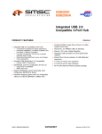
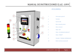
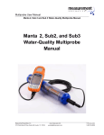
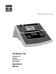
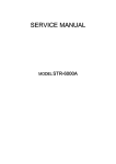
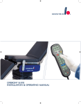
USER'S MANUAL
CONTENTS
SYSTEM DESCRIPTION............................................. 1
OPERATING INSTRUCTIONS................................. 3
SET UP......................................................................... 4
ADJUSTING SETTINGS............................................ 5
CONTROLS & INDICATORS.................................... 6
FRONT PANEL CONTROLS.................................... 7
WIRING/MAINTENANCE........................................ 8
SAFETY CHECKLIST................................................ 9
GLOSSARY OF TERMS...........................................10
ERROR CONDITIONS...............................................11
PIN-OUTS FOR CONNECTORS............................. 12
SPECIFICATIONS..................................................... 13
APPENDIX.................................................................14
Items manufactured by companies other than Smith-Root carry the original manufacturer’s warranty. Please contact
product manufacturer for return instructions.
All Smith-Root, Inc. manufactured products are covered by a one year warranty.
Due to increased handling costs a minimum order amount of $25.00 is required.
Prices are subject to change without notice. SRI reserves the right to make changes of products at anytime without notice.
Smith-Root, Inc. Electrical Field Fish Barrier systems are protected by patent. Ideas, arrangements, drawings, and specifications are the sole property of
Smith-Root, Inc. and are intended for this specific catalog and shall not be used for any other purpose, without written consent of Smith-Root, Inc.
U.S. - 4,750,451 Canada - 1,304,442
Credit & Refund Policy: Customers returning equipment, in new condition, will be given credit to the applicable VISA/Master Card account within five
days from the date of the return. A return authorization must accompany returns. Valid equipment returns include, but are not limited to, ordering incorrect
equipment, funding deficits, and defective equipment returned for reimbursement. All returns are subject to a restocking fee and applicable shipping charges.
The restocking fee is figured at 10% of the purchase price but not less than $20.00. Customers receiving equipment in damaged condition will be referred to
the shipping company for insurance reimbursement.
Rev.005
© 2013 Smith-Root, Inc. Vancouver, WA - USA • Rev. 05
Control # 08117.05
2013
I
EA-1000B
USER'S MANUAL
ELECTROANESTHESIA UNIT
WARNING: HIGH VOLTAGE IS USED IN THE OPERATION OF THIS
EQUIPMENT! DEATH ON CONTACT MAY RESULT IF PERSONNEL
FAIL TO OBSERVE SAFETY PRECAUTIONS. BE CAREFUL TO
AVOID CONTACT WITH ALL CIRCUIT COMPONENTS AND
CONNECTIONS WHILE CHECKING OR SERVICING THIS EQUIPMENT.
SYSTEM DESCRIPTION
power required is 120 VAC to 240 VAC, 60 Hz single phase at 15 amps. The input
Input
power fuses are housed in indicating fuse holders mounted on the front panel.
The polarity of the electrical output supplied by the EA unit can be switched at the front
panel in order to counteract the electrical generation of deposits on the electrodes in the tank
over time.
The output is switched on and off by a low voltage remote control switch. Either a single or
dual footswitch assembly can be connected to the receptacle on the EA unit.
PROCEDURE AT A TYPICAL ELECTROANESTHESIA INSTALLATION
1
2
ELEVATOR
CONTROL
UNIT
CROWDER
CA
TH
OD
AN
E
Fish are herded through crowder and into the Elevator.
3
Elevator lifts fish above electroanesthesia tank and
drops them in.
4
OD
E
ANESTHESIA
TANK
The EA-1000B Electroanesthesia Unit is a high-voltage Direct
Current, (DC), pulsator that puts out a complex waveform capable of anesthetizing fish
placed in the treatment tank. The varying electric field first excites the fish then puts
them into an anesthetized state. The electrical output of the EA unit is engineered to
induce the mildest possible physiological reaction of the fish. The controls should be
adjusted to anesthetize the fish quickly and deeply with the minimum power applied.
The electrical output waveform is applied in two successive stages, each having
selectable peak voltage, waveform, and duration. Stage 1 is a lower voltage, applied as
a preparatory measure for the higher voltage applied in Stage 2. The output is applied
to electrodes mounted in a pair of plastic holding tanks, with one electrode mounted
in the common wall between the tanks (normally the anode or positive electrode), and
the others (normally the cathode or negative electrodes) mounted in the opposite wall
of each tank and tied together electrically. The output is electrically isolated from the
grounded input power circuit to reduce the hazard of shock to personnel who might come
into contact with the output circuit.
A brail basket raises anesthetized fish from the tanks to a workstation.
1
www.smith-root.com
Fish undergo Electroanesthesia cycle for
predetermined time.
Anesthetized fish are lifted out of Electroanesthesia
tank and lifted to sorting table.
There are front panel LED’s to indicate Input Power Ok, Output Power Ok, Stage 1 On, Output
On, Pulse On, and Stage 2 On. There is also a front panel ammeter and a timer display. The
timer can be set to count up or down in seconds; counting down is the default mode. By
default the timer display shows the number of seconds remaining in a treatment cycle. A
treatment cycle is the combined time of Stage 1 and Stage 2. At the end of the treatment
cycle the output is automatically turned off. In addition a front panel audio enunciator sounds
when the output is active. A remote alarm is connected to the EA-1000B via the Remote
Enunciator terminal block behind the front panel. It is used to warn personnel in the area
when the output of the unit is active. The remote alarm must be AC powered and rated at
240 volts or less, and 5 amps or less.
2013
2
EA-1000B
USER'S MANUAL
ELECTROANESTHESIA UNIT
WARNING! UNIT IS NOT WATERPROOF! TO PREVENT WATER DAMAGE
TO THE EA-1000B, MAKE SURE THAT THE LID IS CLOSED DURING
OPERATION AND WHILE CLEANING WORK AREA.
OPERATING INSTRUCTIONS:
Do not install the EA-1000B in an area where it will be directly exposed to the
weather. Do not install the EA-1000B in an area where it will be exposed to
condensation.
Always make sure the EA-1000B is connected to a properly grounded power source.
Before using the EA-1000B for the day inspect all the input and output cables for
damage and repair or replace any damaged cables immediately. Make sure all
connections to the unit and the treatment tanks are tight.
SET UP:
1.The Power switch must be in the Off position (handle down).
2.Check the area to be sure all personnel are in their correct positions, and the safety switches are
not depressed.
3.Ensure that fish are in the the brail basket, which is submerged in the electroanesthesia
tanks.
4.Turn the Power switch to the On position (handle up). Note that after a short time the Input
Power Ok indicator lights.
5.Adjust the Voltage and Time (Sec) switches for each of the two stages to anesthetize the fish
quickly and deeply with the minimum power applied. Any adjustments made while the output is
on will not take affect until the safety switch is released and pressed again. Note that currently
the Waveform Switches select the same output waveform in all positions. These switches have
been provided to allow for the possibility of using different waveforms in the future based on
continuing research into their effectiveness. Until you have gained more experience with the
EA-1000B, start with the settings shown below:
Surplus/Kill
Sorting/Spawning
Stage 1
Do not operate the unit if any of the output indicators are not functioning correctly.
If it becomes necessary to replace a fuse the lamp in the fuse holder cap will light.
When replacing fuses use only fuses of the same type and size as the original: 250V,
10 Amp Slow Blow.
When the EA-1000B is correctly adjusted,
WARNING: The water and
the fish in the treatment tanks will first be
excited during Stage 1 and then anesthetized
the electrodes in the holding tanks
during stage 2. Some experimentation may
carry electrical current capable of
be required to find the optimum settings of
inflicting SEVERE INJURY OR
the controls. Things to take into consideration
DEATH when the Electroanesthesia
would include (but are not limited to) water
Unit is operating! Keep all
conductivity, temperature, power density,
personnel clear of the holding tanks fish size, species, life history stages, and the
and all water in contact with them
physical condition of the fish. For example
when the Electroanesthesia Unit is
salmonids, with extended time in fresh
operating. Ensure that at least two
water, will require adjustments of settings
people on site are trained in
(both voltage and time). Fish behavior and
the condition of fish flesh (for consumption
emergency first aid procedures for
purposes) will also be a concern.
treatment of electrical shock.
This unit is not designed to electrocute the fish,
but rather anesthetize them to the point of non-recovery or close to it dependent
on your needs. We have found that to be effective, the fish must first be subjected
to a low voltage treatment, forcing the fish to be very active for a period of time and
then exposed to a high voltage that forces the fish to stop respiration for a period of
time. The goal is to achieve the targeted fish behavior without creating unnecessary
injury to the fish at any point.
3
www.smith-root.com
Stage 2
Volts
Seconds
130
64
18
56
Stage 1
Stage 2
Volts
18
290
Seconds
56
128
6.Press the safety switch or switches. Note that the enunciator sounds for 5 seconds
before the Output On, and Output Power OK indicators light. Also note the timer is
reset to the combined time of Stage 1 and Stage 2. The timer does not start until the
output becomes active, after the 5 second safety delay. The safety switches must be
pressed throughout the output cycle. If any of the safety switches are released the
output cycle is immediately terminated, and the control circuitry is reset. The timer will
display the time remaining from the previous treatment cycle until the safety switches
are again pressed. When the safety switches are pressed again a new output cycle will
start and the timer display will be reset.
7.After the 5 second turn on delay the Stage 1 indicator, and Output Power OK indicator
light, the timer starts, and the lower Stage 1 voltage and waveform is applied to the
electrodes for the time selected by the Stage 1 Time control.
8.Note that the Pulse On indicator flashes.
9. When the Stage 1 indicator goes out the Stage 2 indicator will light and the higher
Stage 2 voltage and waveform is applied to the electrodes for the time selected by the
Stage 2 Time control.
10. Note at the end of the cycle the Output On, Stage 2, and Pulse On indicators go out,
the enunciator becomes silent, and the timer display shows 0 seconds remaining in the
treatment cycle.
11. Release the safety switch.
12. Raise the brail basket and process the fish.
13. Lower the brail basket and repeat the procedure until all the fish have been processed.
2013
4
EA-1000B
USER'S MANUAL
ELECTROANESTHESIA UNIT
ADJUSTING THE SETTINGS:
f the fish are not sufficiently anesthetized increase the time of treatment. When
Iamount
increasing the settings on the EA Unit, we recommend incrementally increasing the
of time per treatment prior to increasing voltage. This will result in reduced
injury to the fish.
Hemorrhaging in the muscle tissue along the spine of the fish can occur in addition to
vertebral damage. This usually indicates the voltage setting of one or both stages is
too high. These injuries can be greatly reduced by using proper EA settings (voltage,
time or a combination of both).
When setting up the unit we recommend checking for both injuries and recovery
time of the treated fish. When the EA-1000B is adjusted correctly the injury rate
should be very low and the recovery time should be less than 10 minutes for all fish. In
general, decreasing stage 2 voltage or increasing stage 1 time will result in lower injury
rate. Decreasing stage 2 time usually leads to shorter recovery times.
Remember, desired fish response and condition must always be taken into
consideration. There are not any magic settings that work all the time for every
application.
CONTROLS AND INDICATORS:
POWER ON/OFF: Turns power to the EA-1000B on and off.
INPUT POWER OK: Indicator lights when the input power is switched on at the front
panel and the internal circuitry is ready.
POLARITY SWITCH: Reverses the internal connection to the Anode/Cathode
receptacle to enable switching the polarity of the electrodes in the holding tank.
Setting the switch to Normal connects the positive side of the output to the anode
cable and the negative side to the cathode cable. Periodically reversing the polarity
of the electrodes in the tanks helps to prevent the buildup of deposits on the
electrodes.
WARNING!: Do not change the setting of this switch when the output of the
EA-1000B is active! Doing so may damage the switch and can cause severe
injury to any fish in the tanks.
If the injury rate is too high then either decrease the stage 2 voltage or increase the
stage 1 time. Keep in mind that the duration of stage 1 can have a dramatic affect
on injury rates. Injury rates tend to increase with stage 1 times less than 20 seconds.
This is because the fish have not tired sufficiently before the higher stage 2 voltage is
applied.
CONTROL SWITCH: When the remote control safety switch is pressed and
held, the EA will perform 1 complete treatment cycle. If the switch is released
during the cycle, the output is switched off and the control circuitry reset. In a
normal treatment cycle the lower voltage Stage 1 output is turned on after a 5
second warning delay. At the end of Stage 1 the higher voltage Stage 2 begins
automatically. At the end of Stage 2 the output is automatically switched off until
the remote control safety switch is released and pressed again. If the time for either
Stage 1 or Stage 2 is set to 0 that stage is skipped in the treatment cycle.
If the fish are over anesthetized decrease the duration of treatment, usually the stage
2 time.
OUTPUT POWER: Indicator lights when the output is active.
If the fish do not quickly calm down after stage 2 has begun, increase the stage
1 time. If the fish continue to take more than 5 seconds to calm down after the
beginning of stage 2 then increase the stage 2 voltage but take care to watch for an
increase in injuries to the treated fish.
OUTPUT: Indicator lights when the output is active.
Remember that changes to the settings of the EA-1000B do not take affect until
the next time the safety control switch is pressed. Releasing and pressing the switch
again not only changes the settings the machine uses but also resets the treatment
time to the full duration of the stage 1 and stage 2 times. We do not recommend
making changes during a treatment cycle. Rather wait until the cycle has ended then
make changes.
PULSE: Indicator flashes when output pulses are being applied to the electrodes.
There should always be quality control throughout the duration of time when fish are
returning and being held at the hatchery (via filleting of random fish) to ensure the
injury rate is low and the quality of the flesh is still acceptable for its’ intended use.
STAGE 1: Indicator lights during Stage 1 of the output.
STAGE 2: Indicator lights during Stage 2 of the output.
OUTPUT CURRENT: Meter indicates the amount of electrical current flowing
through the electrodes.
STAGE 1 & 2 TIME (SEC) ROTARY SWITCHES: Sets the duration of the output stage
at 8, 16, 24, 32, 40, 48, 56, 64, 72, 80, 88, 96, 104, 112, 128 seconds. If 0 is selected
the stage is not performed.
STAGE 1 & 2 VOLTAGE: Sets the output voltage for the Stage.
Stage 1: 3, 6, 9, 12, 15, 18, 21, 24, 27, 30, 33, 36, 39, 42, 45, 48
Stage 2: 50, 66, 82, 98, 114, 130, 146, 162, 178, 194, 210, 226, 242, 258, 274, 290
TIME: By default, shows the number of seconds remaining in a treatment cycle. The
timer can be programmed to show the number of seconds a treatment cycle has
been running.
AUDIO ALARM: Sounds 5 seconds before the Output is activated and continues
until the treatment cycle ends.
5
www.smith-root.com
2013
6
EA-1000B
USER'S MANUAL
ELECTROANESTHESIA UNIT
FRONT PANEL CONTROLS:
Blue
Gray
Gray -Basket Position Switch
Blue - Foot Switch
Remote Enunciator
www.smith-root.com
Fuse # 1
Fuse # 2
Blue - Anode Out
Green -Ground/Earth
Gray - Cathode Out
7
The input and output power connections, as well as control and external signal
connections are on DIN rail connectors, accessible behind the front panel. See
diagram below for wiring and pin-out details and descriptions on page 12 for further
information.
Gray - Hot 120VAC/240 VAC
Green - Ground/Earth
Blue - Neutral/240 VAC
1. ENUNCIATOR: Sounds when unit
is active.
1
2. TIME ROTARY SWITCHES: Sets
2
the duration of the output on
2
stages 1 & 2
3. WAVEFORM ROTARY SWITCHES:
4
Inactive at this time. This feature is
3
5
currently under developement.
3
6
4. OUTPUT CURRENT METER:
Indicates the amount of electrical
7
current flowing through the
7
cathode circuits.
5. STATUS LEDS:
• Stage 1: Lights when Stage 1 is on.
• Output:Lights when Output is
active for Stage 1 or Stage 2.
8
8
9 10
• Power: Lights when power is on.
• Stage 2: Lights when Stage 2 is
on.
11
12
• Output Power: Lights when
13
14
Output is active.
• Pulse: Flashes when Output is
active.
6. TIME METER: Shows duration of treatment cycle in
seconds.
7. VOLTAGE ROTARY SWITCHES: Sets the voltage of
the output on stages 1 & 2.
8. AC FUSES: Two (2), 10 amps ea. Fuse holder cap
lights up when fuse is blown.
11
9. POWER SWITCH: Turns power to the EA-1000B on
and off.
10. POLARITY SWITCH: Reverses the internal connection to the Anode/
Cathode receptacle to enable switching the polarity of the electrodes in
the holding tank.
11. FOOT-SWITCH CONNECTOR: Allows for the connection of a single footswitch controller. Additional configurations can be connected via the DIN
terminal strip inside the unit, behind the control panel.
WIRING THE CONTROL UNIT
MAINTENANCE:
The EA-1000B requires little maintenance other than keeping the unit clean.
Carefully remove abrasive substances before wiping the unit. The unit can be
cleaned with a mild soap and water solution and a soft cloth.
Do not wash down with a hose.
Before using the EA-1000B for the day inspect all the input and output cables for
damage and repair or replace any damaged cables immediately.
When the EA-1000B is used seasonally we recommend the unit be stored inside
when it is not being used. It should be kept in an area where it will not be exposed
to condensation. Remove foot switch connector and use provided cap to protect
connector.
To maintain safety, fuses must be replaced with the same size and type as the
original.
WARNING! UNIT IS NOT WATERPROOF! TO PREVENT WATER
DAMAGE TO THE EA-1000B, MAKE SURE THAT THE LID IS CLOSED
DURING OPERATION AND WHILE CLEANING WORK AREA.
2013
8
EA-1000B
ELECTROANESTHESIA UNIT
GLOSSARY OF TERMS:
USER'S MANUAL
AC: Alternating current is a common form of electricity in which
the polarity of the electrical signal reverses over time.
SAFETY CHECKLIST:
Before operating unit, make sure that:
•At least 2 people on the crew know how to administer first aid for electric
shock.
•Unit is clean and dry (close lid during use).
•All cables are in good condition, with no cracks or abrasions and that all
termineal connections are in place with no missing or damaged parts.
•Safety control switches are in good condition and functioning properly.
•Indicators and alarms are functioning properly.
•All personal protective equipment is in good condition.
•All electrical connections in the system are clean and tight.
•Electrodes are clean and in good condition, with no loose or damaged
parts.
•Treatment tanks clean and in good condition, with no leaks or damaged
areas.
•Fish handling system is clean and in good condition, with no worn or
damaged parts.
•Power outlet is in good condition and is properly wired.
•Work area is clear, with no trip hazards.
•Floor has a non-slip surface.
•All crew members know where the nearest phone is and the emergency
services number is clearly posted by the phone.
AMMETER: A device used to measure the amount of electricity flowing
in a circuit.
AMPS: The unit of measure for the amount of electricity flowing in a
circuit also called electrical current.
ANESTHESIA A general loss of senses, such as pain, touch, temperature,
etc.
ANODE: The positive lead or electrode of a direct current, DC, power
source.
BRAIL BASKET: A basket made of wire screen or other perforated material.
CATHODE: The negative lead or electrode of a direct current, DC, power
source.
CIRCUIT: Any combination of power sources, wires, electrodes, or
other electrically conductive media through which electrical
current flows.
DIRECT CURRENT: An electrical source, the value of which, does not vary over
time.
ELECTROANESTHESIA: Using electricity to induce an anesthetized state.
ELECTRODE: A device used to apply electricity to a different media or
organism.
ENUNCIATOR: An audible or visual indicator or alarm.
FUSE: An electrical safety device designed to burn out in a safe
manner if more than the rated current flows in the protected
circuit.
HEMORRHAGING: Bleeding.
HERTZ: Abbreviated Hz. The unit of measure of electrical frequency.
Also known as cycles per second or pulses per second.
LED: Light Emitting Diode. A solid state electronic device often
used as a visual indicator.
PEAK VOLTAGE: The maximum voltage that an electrical signal or waveform
attains.
POLARITY: Having both positive and negative terminals or connections.
POLARITY REVERSAL:
Having the ability to exchange positive and negative
terminals or connections.
POWER SOURCE: A source of electricity.
PULSATOR: A machine that generates pulses of electricity.
RATED OR RATING: The amount of electrical voltage, current, or power that a
circuit or device can safely handle.
SINGLE PHASE: An electrical signal having only one pattern that repeats
over time.
VOLTMETER: A device used to measure the amount of electrical pressure
in a circuit.
VOLTS: The unit of measure of electrical pressure.
WAVEFORM:
9
www.smith-root.com
A pattern of electrical output that repeats over time.
2013
10
EA-1000B
USER'S MANUAL
ELECTROANESTHESIA UNIT
TIME (SECONDS)
8
80
88
48
40
Error
conditions shown on the front
panel
LED’s only appear as long as
96
9696
3232
32
2424
24
104
104
104
the
control switch in pressed.
1616
16
112
112
112
8 8 0 0128
128
0 128
OUTPUT CURRENT
STAGE 1
H
I
J
L
E
D
N
STAGE 2
WAVEFORM
PULSE
OUTPUT
B
A
O
P
INPUT
OUTPUT
POWER
POWER
E
D
N
PULSE
OUTPUT
M
B
A
INPUT
O
P
OUTPUT
AC FUSES
#1
#2
POWER
TIME
(SECONDS)
21
18
15
12
9
10A
24 27 30
6
POWER
VOLTAGE
10A
WAVEFORM
TIME
O
O112
C C2
B B2 A A0 P128
P
POLARITY
NORMAL
OFF
STAGE 1
WAVEFORM
OUTPUT
#2
POWER
10A
OUTPUT
11
WARNING
INPUTLIGHT
SERIAL NO.
POLARITY
B2
ON
NORMAL
AC FUSES
POWER
VOLTAGE
REVERSE
OFF
EA-1000B
BASKET
OUTPUT
SENSOR
WARNING
FOOT-SWITCH
LIGHT
POLARITY
162 178 194
210
146
130
226
114
98
82
242
258
274
66 50 290
ELECTROANESTHESIA
STAGE 2
SYSTEM
BASKET SENSOR
SERIAL NO.
AC FUSES
O
112
P
A0 128
TIME
ELECTROANESTHESIA
STAGE 2
SYSTEM
www.smith-root.com
M
96
C2
STAGE 1 + PULSE ON LED
FLASHING: Indicates an output
42258
peak
current overload.
45274
EA-1000B STAGE 1
K
80
L
88
N
104
POWER
POWER
WAVEFORM
(SECONDS)
10A
30194
2416227178
33210
36226
39242
I 72
J
H 64
56
E
32
D
24
6 663 5048290
3 48
G
48
F
40
SERIAL NO.
AC FUSES
112
0 128
WAVEFORM
PULSE
VOLTAGE
REVERSE
STAGE 2
INPUT
242
88
258
96
274
290 104
STAGE 2
OUTPUT
#1
50
8
(PEAK AMPS)
M
M 96
VOLTAGE
TIME (SECONDS)
162 178 194
210
146
64 72
130 56
48
80226
OUTPUT CURRENT
N
N104
ON
VOLTAGE
O
112
P
A0 128
(SECONDS)
16
I J 72
J
H I 64
H 56
G
G 48
K
K 80
L
L 88
F
F 40
POWER
POWER
B2
STAGE 1 + OUTPUT POWER OK LED
114
40
FLASHING: Indicates an output power
98
32
82
overload.
24
66
33
21146
STAGE
1 + INPUT POWER OK LED
36
18130
FLASHING:
Indicates a problem 15114
39
1298
42
with
the AC power to the unit.
45
9 82
AGE 1
C2
TIME (SECONDS)
E
E 32
D
D 24
SERIAL NO.
M
96
N
104
POWER
POLARITY
Gray -Basket Position Switch
L
C
STAGE 2
WAVEFORM
K
F
POWER
K
80
L
88
Blue - Foot Switch
J
OUTPUT
Fuse # 1
Fuse # 2
Remote Enunciator
(PEAK AMPS)
I
INPUT
STAGE 1 STAGE 2
OUTPUT CURRENT
STAGE 1
H
O
O112
C C2
B B2 A A0 P128
P
STAGE 1 LED FLASHING: Indicates
the control switch was pressed
when the power switch was turned
on.
I 72
J
H 64
56
E
32
D
24
30194
2416227178
33210
21146
64647272
56
56
36
18130
4848
8080226
15
3988
114
242
88
40
40
258
1298
42
9696
3232
45274
9 82
2424
104
6 663 5048290104
1616
112
112
8 8 0 0128
128
AGE 1
G
G
48
F
40
PULSE
OUTPUT
WAVEFORM
WAVEFORM
N
N104
VOLTAGE
TIME (SECONDS)
33
21
64 72
36
18 56
48
80
15
39
88
40
12
42
96
32
45
24 9 6
104
48
3
16
112
8 0 128
All cabling is routed through electrical conduit and enters the EA-1000B box at
the bottom through the provided knock-outs. Each circuit is connected at DIN rail
terminals to assure proper mating.
112
0 128
Blue - Anode Out
Green -Ground/Earth
Gray - Cathode Out
24 27 30
8
Gray - Hot 120VAC/240 VAC
Green - Ground/Earth
Blue - Neutral/240 VAC
S)
PIN-OUTS FOR DIN RAIL CONNECTIONS:
96
104
Blue
Gray
TIME
STAGE 2
M
M 96
E
E 32
D
D 24
(SECONDS)
STAGE 1
WAVEFORM
WAVEFORM
I J 72
J
H I 64
H 56
G
G 48
K
K 80
L
L 88
F
F 40
M
C
80
88
(PEAK AMPS)
K
F
56 64 72
OUTPUT CURRENT
(PEAK AMPS)
G
TIME (SECONDS)
EA-1000B ERROR CONDITIONS:
32
24
16
TIME (SECONDS)
565664647272
4848
8080
8888
4040
#08877 REV. 006
48
40
56 64 72
INPUT POWER BLOCK:
DIN Block/Plug Socket:
ANODE CATHODE BLOCK:
DIN Block/Plug Socket:
Green DIN/Socket # A: Green wire, Earth
ground
Blue DIN/Socket # B: White wire, Neutral
power
Gray DIN/Socket # C: Black wire, 240 VAC
power
Not used/Socket # D: Red wire, 240 VAC
power
Gray DIN/Pin # A: White wire, Tank
anode
Blue DIN/Pin # B: Black wire, Tank
cathode
Green DIN/Pin # C: Green wire, frame
ground
CONTROL SWITCH PLUG:
DIN Block/Plug Socket:
Alternate connection to two switches to
operate in series on external MS connector.
Blue DIN/Pin # A:Switch # 1 connection # 1
Blue DIN/Pin # B:Switch # 1 connection # 2
Gray DIN/Pin # C:Switch # 2 connection # 1
Gray DIN/Pin # D:Switch # 2 connection # 2
Connection to a single switch on external MS
connector.
Gray DIN/Pin # A: Switch connection #1
Blue DIN/Pin # D: Switch connection #2
FOOT-SWITCH
#08877 REV. 006
S)
2013
12
EA-1000B
USER'S MANUAL
APPENDIX
ELECTROANESTHESIA UNIT
SMITH-ROOT MODEL EA 1000A/B ELECTROANESTHESIA SYSTEM
SPECIFICATIONS:
STANDARD OPERATING PROCEDURES
Input Voltage: 120 to 240 VAC 60 Hz single phase 10 Amps.
Fuse: 250V 10A Slow Blow, Bussman # 10A or Littlefuse
# 32610
Output Voltage: Stage 1: 3 to 48 volts in 3 volt steps.
Stage 2: 50 to 290 volts in 16 volt steps.
Output Current: 3 Amps maximum.
Output Waveform: Burst of 3 rectangular pulses, 2.08 milliseconds
wide 10% duty cycle, repeated at 15 Hz rate.
Output Duration: 0 to 256 seconds, set with Stage 1 and Stage 2
time switches.
Output Polartity: Normal or reverse user selectable.
Dimensions: 17” W X 10 1/2” D X 19 5/8” H
(43.18 cm W X 26.67 cm D X 49.8 cm H)
Weight: 29 1/4 Lbs. (13.26 Kg)
Operating Temperature 32 to 104 F
Range: (0 to 40 C)
Storage Temperature Range: -0 to 150 F
(-18 to 65 C)
IMPORTANT NOTE: This technology must not be used without first receiving hands-on
training in safety and operating procedures from qualified, trained technicians.
INTRODUCTION: The EA 1000A/B induces fish sedation in two sequential stages, a
low voltage phase (Stage 1) followed by a high voltage, electronarcosis phase (Stage
2). Salmonids should never be exposed to high voltage without a prior low-voltage
exposure unless euthanasia is desired. The low-voltage stage promotes rapid movement
and physically prepares fish neurotransmission physiology for the high-voltage stage that
follows, thus avoiding violent muscle contractions that can induce stress or cause injury.
OPERATIONAL PROCEDURES: The Model 1000A/B EA System uses a 5-second delay
from foot-switch initiation before electricity is applied to fish. The foot-switch (which
helps ensure crew safety) must be applied throughout the entire Stage 1 and Stage 2
cycles. Premature release of the foot pedal will instantly terminate exposure and reset the
timer and control circuitry, thus it is important not to interrupt the cycle unless an unsafe
operating condition warrants doing so. Never adjust settings while the foot-switch is
engaged or damage to the EA unit can result.
Once initial setup has been completed and successfully trialed on a cross-section of test
fish (please see below), the settings should be recorded and posted onsite. Each day prior
to exposing fish to the electrosedation field, the operator must confirm that the desired
EA1000A/B settings have been selected (and not inadvertently altered).
Water conductivity, temperature and fish species are among the variables that may
require adjustments to settings. It is therefore recommended that such parameters be
monitored on a regular basis.
If dark bands (called “branding”) appear on multiple fish, this may be an indication that
fish are being injured (and that downward adjustments must be made to settings).
SUGGESTED OPERATIONAL SETTINGS: For initial set-up, only two to three fish should
be used at a time. The determination of optimum settings may require several tests.
Stage 1 voltage should be just high enough to make the fish move excitedly. In the Pacific
Northwest where conductivities are moderately low (<100 mS/cm), voltage for Stage
1 is commonly set in the range of 18-30 V for 24 to 48 seconds. Stage 2 voltage in the
Pacific Northwest is commonly set in the range of 114-194 V for 32 to 68 seconds. Stage 2
voltages have the potential to injure fish, so operator care is necessary. Facilities with lowconductivity water (<30 mS/cm) may need to add salt to the treatment tank water so that
sedation can be achieved at moderate voltages.
The operator should always start at the lowest voltage and exposure times mentioned
above. If sedation is not initially achieved after both stages are administered, Stage 1
exposure time should be increased in up to 8-second increments. If sedation is still not
achieved, Stage 2 exposure time should be increased by 8 s increments up to 60 s. If
sedation is still not attained, Stage 2 voltage should be increased by 16-V increments and
re-assessed until sedation is achieved. Stage 2 voltage will likely be less than or equal to
194 V. The operator may want to try slightly higher voltages and reduced exposure times,
all the while examining fish for branding marks. Detailed notes and record keeping will
prove to be valuable allies in achieving successful fish sedation with the Smith-Root Model
EA 1000A/B System and in reporting results.
CONTACT INFORMATION: Please consult Smith-Root (360-573-0202) if further guidance
is needed or if you are having any issues in achieving safe, successful fish sedation.
13
www.smith-root.com
2013
14