1
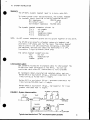
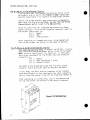
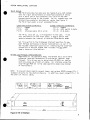
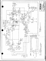
CP-300 & TW-12
Belt-Pack & Interface
Two-Wire System
INSTRUCTION
and
SERVICE MANUAL
CA)
ClearCor®e
Intercom systems
1111 17th Street * San Francisco, California 94107 * 415-861-6666
CLEAR-COM 810044
TW/10-84 REV B
CLEAR-COM CP-300 BELTPACK STATION
& TW-12 TWO-WIRE INTERFACE UNIT
OPERATION & SERVICE MANUAL
Contents
Page #
Introduction to the Belt-Pack & Interface...I
System Installation .......................... 3
Headsets
Interconnect Cable
CP-300 in a Single-Channel System
CP-300 in a Two-Channel System
TW-12 Set-Up
Loop-Through Interconnection
6
CP-300 Operating Controls ..........
7
Parts Listings ..........
8
Specifications ..........
Illustrations
Figure 1: System Interconnection ........... 3
Figure 2: CP-300 Belt-Pack ................. 4
Figure 3: TW-12 Interface .................. 5
9
...........................
CP-300 Schematic .
11
...........................
.
TW-12 Schematic
CLEAR-CON CP-300 BELT-PACK
Operation & Service Manual
ADDENDA
CP-300 "Call" Signalling
(replaces "Optional Signalling" section of Introduction to the
Belt-Pack; page 1, column 2)
The signalling option for the CP-300 provides a visual alert for
users who aren't listening to the intercom. Pressing the CP300's CALL button sends a special call-signalling voltage (either
a 20 kHz tone or a positive DC voltage) onto the intercom channel
currently in use. This voltage is detected by all other stations
which are switched to that channel, causing their call lights to
turn on.
The 2-channel/1-channel mode-select switch sets the signalling
method: a tone for 2-channel or "TWi operation, or DC voltage for
single channel (standard Clear-Com) use.
The signalling option requires installation of a switch/light
button and an additional PC assembly.
Headsets
(see System Installation, page 3)
The headset used with the CP-300 should have a rated mic output
level of -55 dBv.
CP-300 as a two-wire /two-channel station
(see System Installation, page 4)
Using the CP-300 as a two-channel station requires connection to
a TW-12 Interface Unit OR connection to an existing "TW' (twowire) two-channel intercom system. The CP-300's side panel contains a recessed "mode-select" switch, which must be set to the
"2-CH MODE" position (refer to Figure 2 for switch location).
CLEAR-COM 810044
TW/5-85 REV B
CLEAR-COM CP-300 BELT-PACK STATION & TW-12 INTERFACE UNIT
OPERATION MANUAL
.
1. INTRODUCTION TO THE BELT-PACK & INTERFACE
The Clear-Com CP-300 is a portable
belt-pack intercom that allows communication on two channels,
using
standard two-conductor microphone
cable.
The CP-300 is different
from other Clear-Com Stations because it requires connection to an
interface unit, Model TW-12, to
utilize its full capabilities.
O
When the CP-300 is used in its twochannel/two-wire mode, two audio
channels are transmitted on one
cable: channel A audio and DC power
on one of the wires, channel B
audio on the other wire.
The System must include the TW-12 Interface when two intercom channels are
required on one cable.
(Clear-Com
typically uses one cable to support
one audio channel plus power, or it
uses multi-pair cable for two or
more channels.)
The
CP-300 features Clear-Com's
excellent speech intelligibility in
all high- and low-noise environments.
It also includes a mic
limiter, which holds the output
relatively constant over a 30 dB
input range.
The CP-300 has the
same
pin-to-pin connections and
functions as RTS intercoms (e.g.,
RTS Model BP-300),
with better
performance.
A unique CP-300 feature is its
switch-selectable operation as a
two-channel/two-wire station or as
a "standard" one-channel Clear-Con
station.
It operates in a standalone, two-channel system or combined in a system with standard
Clear-Com Stations.
Refer to the
system diagrams, page 3.
Other CP-300 features include its
"user-friendly"
control
lay-out,
including the rocker switch for
channel-selection (A or
B),
a
three-position mic switch (on/off/
momentary on), and a low-profile
volume control.
The controls are
different sizes to facilitate adjustment by touch only.
Al I controls are protected by the raised
lip of the belt-pack's chassis.
Optional Signalling
The Visual Signalling function, a
typical Clear-Com feature, is configured differently in the CP-300
than it is in standard Clear-Com
Stations.
The CP-300 uses a 20,000 Hz signal,
transmitting it on the audio channel selected for communicating (A
or B). This signal is detected by
the other CP-300's which are using
that same channel (A or B), causing
the CP-300 call lamps to light up.
When the signalling option is included in the CP-300, a call lamp/
button is added to the belt-pack's
chassis.
The system of signalling
is determined by the one-channel/
two-channel mode switch on the CP300 operation;
it switches the
signallirg circuitry from DC mode
(standard Clear-Com) to the 20k Hz
signal used in the 'TW" system.
The CP-300's headset amplifier provides power to drive a standard
Clear-Com headset to levels greater than 110 dB SPL, without any
distortion. The belt-pack operates
with either a dynamic or a carbon
headset, providing an input connector for each one.
The CP-300 also incorporates "automatic headset detection,"
which
mutes the mic pre-amp when the
headset is not plugged in. Therefore an unused yet on-line beltpack doesn't cause background noise.
(continued)
CP-300 and TW-12 Description, continued
The belt-pack provides a sidetone
adjustment, which allows the user
to vary the level of his/her voice
(full on to 25 dB null) as heard in
the headset. This control need be
set just once, if at all, even if
other intercom stations join or
leave the intercom network.
TW-12
The TW-12 Interface connects between the CP-300 Belt-Pack(s) and a
standard Clear-Com Power Supply or
Its function is to
Main Station.
translate audio line levels and
and to modulate
call signal Iing,
one of the two audio channels onto
The TW-12,
the DC power line.
rackspace-saving
a
in
is
which
mount chassis (1.75" high), contains no operational controls extoggle
for a Mode-Select
cept
switch.
The TW-12* translates levels and
voltages from two separate ClearCom channels, and provides the twowire, two-channel output on mic
cable. An auto-termination feature
prevents oscillation in partiallyThe TW-12,
systems.
connected
which typically receives its power
through the connection to ClearCom, translates the visual call
signalling between the two systems
(tone to DC & vice versa).
2
The TW-12 can also be used to link
the Clear-Com System with a twowire, two-channel intercom system
The
RTS's "TW" System).
(e.g.
Interface supports RTS BP-300 beltpacks as well as Clear-Com's CP-300
belt-packs.
0
When the TW-12 is used to link a
Clear-Com System with a two-wire
system, the number of
two-channel
intercom stations that may be contained within both systems is only
limited by the capacity of the
power supplies in the respective
systems.
The ability of the TW-12 to support
intercom stations is only limited
when it functions as support for a
stand-alone two-wire, two-channel
The TW-12 supports up to
system.
ten (10) two-channel/two-wire in,tercom stations with signal ling or
up to 16 such intercoms without the
signalling function (Clear-Com CP300, RTS BP-300, or equivalent).
The TW-12, once set up, is transpaIts
rent to the intercom users.
one control is a toggle switch that
selects between internal termination (for "TW" belt-packs) or external termination (for interfacing
with an RTS-type power supply).
W
II. SYSTEM INSTALLATION
Headsets
The CP-300's dynamic headset input is a 4-pin, male XLR.
To insure proper level and performance, the dynamic headset
(or handset) should have the following characteristics-Mic Impedance:
150-250 ohms
Mic Output Level:
-55 dB
Ear Element Impedance: 50-2000 ohms
The dynamic headset connector pin-out is:
Pin 1:
mic common
Pin 2:
mic hot
Pin 3:
headphone common
Pin 4:
headphone hot
NOTE:
Do NOT connect headphone ground and mic ground together at any point.
The CP-300 also accepts a standard carbon mic headset, and
provides a 1/4" phone jack for the input. The carbon headset
should contain a 50 ohm carbon-type microphone, a 600-1000
ohm earpiece, and the cord should be terminated in a 1/4",
3-conductor (ring/tip/sleeve) phone plug.
The carbon headset connections are:
Tip:
mic hot
Ring:
headphone hot
Sleeve:
ground
Interconnect Cable
Use standard 2-conductor microphone cable to interconnect the
CP-300 with other belt-packs or the TW-12. You can use
unshielded cable where AC interference is not a problem.
We recommend rubber-insulated and jacketed cable, such as:
Belden 8413 or equivalent (24 ga., stranded conductors) for
lines running up to 500 feet in length;
Belden 8412 or equivalent (20 ga., stranded conductors) for
lines running 500-5000 feet in length;
Belden 8428 or equivalent (18 ga., low-capacity) for lines
greater than 5000 feet in length.
FIGURE 1: System Interconnection
CS-210
TW-12
CP-300's in 2-CHrmode
A 13
TO
(loop-through)
RM-120A
KB-112
OTHER
TW'
STATIONS
RS-10A
P-Box
lA
B
TO
3 CLEAR-COM
Typical mixed standard and 'TW" two-channel system (portable)
3
SYSTEM INSTALLATION, continued
The CP-300 as a Single-Channel Station
First be sure that the recessed two-position switch on the
belt-pack's side is set to the "SINGLE CH MODE (select B)"
position (see Figure 1 for location of mode-select switch).
Second, the CP-300 operator must communicate on Channel B
when using the single-channel mode; be sure that the CP-300
Channel-Select switch is set to the "B8"position.
Bring mic cable from the Clear-Com Main Station or Power
Supply and plug it into the D3F connector labelled "input" on
the CP-300. The pin-out is-Pin 1: Common
Pin 2: +VDC
Intercom Audio
Pin 3:
After completing all connections, plug in the headset and
turn up the volume. The Station is now ready to operate.
The CP-300 as A Two-Wire/Two-Channel Station
This mode requires the TW-12 to support the CP-300. First be
sure that the CP-300 mode-select switch is set to the "2-CHl
In this mode,
MODE" position (see Figure I for location).
extension
and
input
the pin-out assignment for the CP-300
connectors is-Pin 1: Common
Pin 2: +VDC and Channel A Audio
Channel B Audio
Pin 3:
The INPUT to the CP-300 MUST come from the TW-12 output
connector (3-pin male XLR) labelled "System Interface."
In this mode, the TW-12 must be connected to two standard
Clear-Com channels via the interface's two input connectors,
one for Clear-Com channel A and one for Clear-Com channel B.
After completing all connections, plug in the headset and
turn up the volume. The Station is now ready to operate.
(9347
I
4
t
Figure 2: CP-300 Belt-Pack
SYSTEM INSTALLATION, continued
TW-12 Set-Up
The TW-12 provides two male and two female 3-pin, XLR connedtors for input and extension of Clear-Com channels A and B,
plus a third set of XLR connectors for use with the twochannel/two-wire end of the system. For all connections, use
standard two-conductor shielded mic cable. See Figure 3.
The TW-12 rear panel pin-out assignments are:
Clear-Com System Connectors:
Pin 1:
Common
Pin 2:
+VDC
Pin 3:
Intercom Audio (Ch A or B)
System Interface Connectors:
Pin 1: Common
Pin 2: +VDC and Ch A Audio
Pin 3: Ch B Audio
The TW-12, once set up, is transparent to the user.
It has
only one control on the front panel: a toggle switch that
selects between the internal or external termination mode.
Set this switch to the "2-Channel Station" position to support TW-type belt-packs (internal termination); or set it to
the "System Interface" position for interfacing the Clear-Com
System with a TW-type system that includes its own power
supply (external termination).
0
CP-300 Loop-Through Interconnection
Regardless of its operation mode, the CP-300 has a 3-pin male
connector labelled "extension" to provide an internal loop-
through.
This allows you to daisy-chain CP-300's or similar
stations along one stretch of cable. All stations using the
loop-through MUST be in the same operation mode (one channel
or two-channel).
NOTE: To prevent shock hazard, ground loops, and noises, NEVER connect Pin 1
(common) directly to the station chassis. In addition, never connect Pin 1 to
the shell of the mic cable.
711
cv~~~~~~~~fR
T__/F~r
.~~~~~~~~~~~~~~_1
7-r
sfUea_
45
(t',5 /,
_t44 201)d
K~~~~~~
0
(402 60)
Figure 3: TW-12 Interface
5
111.
CP-300 OPERATING CONTROLS
The MIC SWITCH turns the headset
mic ON and OFF, and includes a
third position marked "on (mom)"
(momentary on) for quick messages.
The CHANNEL-SELECT SWITCH allows:
1) communication on Channel A or on
Channel B, when the CP-300 uses
the 2-Channel mode, OR
2) communication on one channel (3)
when the CP-300 uses the SingleChannel mode.
Note that the Channel-Select Switch
must be set to "B" when the CP-300
standard
operator is using the
Clear-Corn single-channel mode.
The VOLUME knob adjusts the
level in your earphone(s).
audio
The SIDETONE adjustment is located
on the side of the belt-pack, and
is used to vary the amount of your
voice as heard in your headset. It
does not affect the level of incoming or outgoing signals, and is
set at the factory to be approximately 6 dB lower than incoming
6
To re-set it, locate the
signals.
unmarked hole (which contains a
Plug in your headset,
trimpot).
insert a small-bladed screwdriver
through the hole, and engage the
slot on the trirnpot. Turn up the
headset volume all the way, and
start talking to yourself while
A
slowly turning the screwdriver.
null point will be found where you
can barely hear yourself; the normal setting is anywhere to the left
of the null.
The optional VISUAL CALL SIGNALLING
function follows the setting of the
belt-pack's Channel-Select switch;
for instance, if you are talking on
channel A, pressing the Call switch
illuminate the lights at all
will
on
other Stations communicating
stay
will
channel A. Call lights
on for as long as the switch is
depressed. The CALL LIGHT lights up
attract your attention when
to
another Station operator (using the
same channel) activates the Call
signal.
IV. PARTS LISTING
CP-300 Belt-Pack Without Signal Option
part #
150048
210002
210003
210013
210050
240031
250041
250233
250234
640007
710152
description
qty.
capacitor, lOOpF 1kv 20% RF
1
input connector, 3-pin female XLR
1
output connector, 3-pin male XLR
1
dynamic headset input, 4-pin male XLR 1
carbon headset input, 1/4" phone jack 1
volume control knob
1
large belt-clip
1
CP-300 chassis
1
CP-300 chassis cover
1
hole plug
1
CP-300 printed circuit board assembly I
CP-300 Belt-Pack With Signal Option
same as above EXCEPT: delete part #640007, hole plug
and add:
510064
Call switch with lamp
1
710153
CP-300 signalling circuit board assy. I
TW-12 Two-Wire Interface
210002
210003
240017
250073
250152
250231
250232
510006
710147
input connector, 3-pin female XLR
3
output connector, 3-pin male XLR
3
rack handles for 1.75' chassis
2
1.75" mainframe chassis
1
mainframe chassis cover
1
two-wire interface front panel
1
two-wire interface rear panel
1
mini-toggle switch, 2-position
1
two-wire interface printed circuit asy.1
7
V. CP-300 SPECIFICATIONS
AMPLIFIER DESIGN: Solid-state, low-noise I.C. amps; current-limited and shortcircuit-protected, with reverse polarity protection.
MICROPHONE PRE-AMPLIFIER
1k ohm
Mic Input Impedance:
50 dB
Mic Pre-amp Gain:
-32 dB
Max Input Before Clipping:
250-12k Hz, *5dB
Freq. Response:
10 ma nominal
Carbon Mic Current:
8 dB change in
Limiter Range:
output for 30 dB change in input
HEADPHONE AMPLIFIER
Load Impedance Range:
Output Level:
50-2k ohms
+15 dBm into
300 ohm load
>110 dB SPL
Headset Level:
(with dynamic Clear-Com headset)
<0.1% THD 6 I kHz
Distortion:
24 dB
Amplifier Gain:
150-12k Hz, 42dB
Freq. Response:
CONNECTORS
(1) 4-pin male, D4M
Headset:
& (1) 1/4", 3-cond. phone jack
- two 3-pin XLR, I male
Line:
and 1 female for loop-through
VI.
GENERAL
Station Bridging
>20k ohms (200-10k Hz)
Impedance:
-6 dB, +3 dB max
Avg. Line Level:
Sidetone Adjust: 25 dB null-full on
Call Light
(receive) 4 volts DC
Sensitivity:
(send) IlVDC
Power
25 ma quiescent
Requirements:
12-32v @ 25ma
DC Voltage Range:
average, 25v nominal
Max. Number of CP-300s with TW-12:
16
without signalling,
with signalling, 10
PHYSICAL CHARACTERISTICS
3.78" x 5.1" x 1.6"
Dimensions:
14.5 oz
Weight:
circuit)
signal
(without
Ambient Operating
0-60 C (32-1400 F)
Temperature:
0-90% relative humidity
Humidity:
TW-12 SPECIFICATIONS
LINE CHARACTERISTICS, CLEAR-COM SIDE
-15 dBv nominal, 0 dBv max
Level:
before clipping
AC termination
ohm
200
Impedance:
5000 ohm DC termination
LINE CHARACTERISTICS, TW SIDE
-5 dBv nominal, +3dBv max
Level:
200 ohm AC
Impedance:
GENERAL CHARACTERISTICS
+12 dB
Gain, Clear-Com-to-TW:
-12 dB
Gain, TW-to-Clear-Com:
200-10k Hz, 13 dB
Freq. Response:
Power Requirements: 12-32 VDC, 50ma
quiescent plus current for TW side
500ma max
TW Power Capacity:
(6-12 stations)
SIGNALLING, TW SIDE
Frequency:
Freq. Tolerance:
Tone Level:
20k Hz
;100 Hz send,
+500 Hz receive
-6dBv minimum send,
-30dBv maximum receive
SIGNALLING, CLEAR-COM SIDE
4 VDC maximum receive,
11 VDC minimum send
DIMENSIONS
1.75" H x 19" W x 6" D
44mm H x 483mm W x 152mm D
0 dBv is referenced to 0.775 volts RMS
8
[1 1 1CD
0
:
0) La~~~~~~~~~L
Li~~~~~~~±c
,
U F-
cl e11
~
£
<
X
.
12
,
111
U+1~~~~~~~~~~~~~~~~*
cn
NOV
woo
-*
0
zT,
~ ~~~~L
L.J~
0
<n
0~~~~~~~~~~0IL
NJ~~~~~~~~~~~~
rq~~~~~~~~~~~
'-a
0~~~~~~~~~~~~~L
0
Xt ,Y~~~~kbo,..
3~~~~~~~~~~~~~~~~~~~~~~~~~~~~~~~~~~~~~~~~~f
g-'
oo
0,__--a
wi~~~~~~~~~~~~~~~~~~~~~~~~~~e~
W
vr
L, 9
% v
d..I.28...
_____
<
N
!
:
M
~~~~~wL
H1 C;;S
H
c
0
1T
|,CR~~~+1
r
T
auO
zo
+X
~JSI
~~~~~~~~~~~~~~~~~~~~~~~6
------ ~
gwo
HH
A_
-_I/-
- -
I
_
_
__
_._
_
a
I~~~~~~~~~~~~~~~~~C
~~~~~~i
_
_ _ _ _ _ _ _ _ _
U
_
Lj~~~~~~~~~~~~~~~~~~~~~~~~~~~~~~~~~~~~~~~~~~~~~~~~~~~~~~~~~~~~~~~~i
,
1-~1
N1,>
,m
f~~~~~~~~etc1 ~~~~~~~~~~~L
'
r
INa3llg
~~~~~~~~~~~~~~~~~~~~~~~~~~~~S
_.
>
-
-
rd~~~~~~C
6C
u
z
a
-J~
~ ~~JZ
0-
s
f~~~~T
rt
L
~
xo
,,
~ ~
>E
I-J
,
1
4
NI
YE
=
-I
IZ~~~~~~~~~~~~~~~~~~~~~~~~~~~~~~~~~~~~~~~~~~~~~~~~~~~~~~~~~I
-
00,~~~~~~~~~~~~~~~~~~~~~~
~~~~~~ ~ ~ ~ ~ ~ ~ ~ ~ ~ ~ ~ ~ ~ ~ ~ ~~~~i
Li
-U
Li±
2
-
z
~~~~~~~~0IC
-
![AD75C20SNJ2 AJ65BT-D75P2-S3-MR-J2[ ]A](http://vs1.manualzilla.com/store/data/006537624_3-ebac58f9411437eb9480ea10c1970d7b-150x150.png)