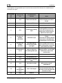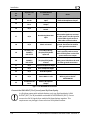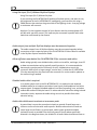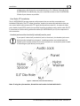
1
SV-INTERCOM-2S Installation and User’s Guide This product is not approved for installation in type certificated aircraft Document 102061-000, Revision A June, 2013 Copyright © 2013 by Dynon Avionics, Inc. Permission to print this this manual is granted to third parties Contact Information Dynon Avionics, Inc. st 19825 141 Place NE Woodinville, WA 98072 Phone: (425) 402-0433 - 8:00 AM – 5:00 PM (Pacific Time) Monday – Friday Dynon Technical Support available 7:00 AM–4:00 PM (Pacific Time) Monday – Friday Email: [email protected] Fax: (425) 984-1751 Dynon Avionics offers online sales, extensive support, and frequently updated information on its products via its Internet sites: www.dynonavionics.com –Dynon Avionics primary web site; including: docs.dynonavionics.com – Current and archival documentation. downloads.dynonavionics.com – Software downloads. support.dynonavionics.com – Support resources. store.dynonavionics.com – Dynon’s secure online store for purchasing all Dynon products 24 hours a day. wiki.dynonavionics.com – Dynon’s Documentation Wiki provides enhanced, extended, and frequently updated online documentation contributed by Dynon employees and customers. forum.dynonavionics.com Dynon’s Internet forum where Dynon customers can interact with each other and Dynon Avionics. A key feature of the forum is that it allows the exchange of diagrams, photos, and other types of files. newsletter.dynonavionics.com – Dynon’s email newsletter. blog.dynonavionics.com – Dynon’s blog where you can find new and interesting Dynon-related content. register.dynonavionics.com – Register your Dynon Avionics product. license.dynonavionics.com – Redeem certificates for Navigation Mapping Software, Synthetic Vision, and other features for license codes that add new functionality to your SkyView system. Copyright 2013 Dynon Avionics, Inc. All rights reserved. No part of this manual may be reproduced, copied, transmitted, disseminated or stored in any storage medium, for any purpose without the express written permission of Dynon Avionics. Dynon Avionics hereby grants permission to download a single copy of this manual and of any revision to this manual onto a hard drive or other electronic storage medium to be viewed for personal use, provided that such electronic or printed copy of this manual or revision must contain the complete text of this copyright notice and provided further that any unauthorized commercial distribution of this manual or any revision hereto is strictly prohibited. Information in this document is subject to change without notice. Dynon Avionics reserves the right to change or improve its products and to make changes in the content without obligation to notify any person or organization of such changes. Visit the Dynon Avionics website (www.dynonavionics.com) for current updates and supplemental information concerning the use and operation of this and other Dynon Avionics products. Limited Warranty Dynon Avionics warrants this product to be free from defects in materials and workmanship for three years from date of shipment. Dynon Avionics will, at its sole option, repair or replace any components that fail in normal use. Such repairs or replacement will be made at no charge to the customer for parts or labor performed by Dynon Avionics. The customer is, however, responsible for any transportation cost and any costs that are incurred while removing, reinstalling, or troubleshooting the product. This warranty does not cover failures due to abuse, misuse, accident, improper installation or unauthorized alteration or repairs. THE WARRANTIES AND REMEDIES CONTAINED HEREIN ARE EXCLUSIVE, AND IN LIEU OF ALL OTHER WARRANTIES EXPRESSED OR IMPLIED, INCLUDING ANY LIABILITY ARISING UNDER WARRANTY OF MERCHANTABILITY OR FITNESS FOR A PARTICULAR PURPOSE, STATUTORY OR OTHERWISE. THIS WARRANTY GIVES YOU SPECIFIC LEGAL RIGHTS, WHICH MAY VARY FROM STATE TO STATE AND IN COUNTRIES OTHER THAN THE USA. IN NO EVENT SHALL DYNON AVIONICS BE LIABLE FOR ANY INCIDENTAL, SPECIAL, INDIRECT OR CONSEQUENTIAL DAMAGES, WHETHER RESULTING FROM THE USE, MISUSE OR INABILITY TO USE THIS PRODUCT OR FROM DEFECTS IN THE PRODUCT. SOME STATES AND COUNTRIES DO NOT ALLOW THE EXCLUSION OF INCIDENTAL OR CONSEQUENTIAL DAMAGES, SO THE ABOVE LIMITATIONS MAY NOT APPLY TO YOU. Dynon Avionics retains the exclusive right to repair or replace the instrument or firmware or offer a full refund of the purchase price at its sole discretion. SUCH REMEDY SHALL BE YOUR SOLE AND EXCLUSIVE REMEDY FOR ANY BREACH OF WARRANTY. These instruments are not intended for use in type certificated aircraft at this time. Dynon Avionics makes no claim as to the suitability of its products in connection with FAR 91.205. Dynon Avionics’ products incorporate a variety of precise, sensitive electronics. SkyView products do not contain any field/user-serviceable parts. Units found to have been taken apart may not be eligible for repair under warranty. Additionally, once a Dynon Avionics unit is opened up, it is not considered airworthy and must be serviced at the factory. Revision History Revision Revision Date A June, 2013 Description Initial release Table 1– Revision History iv SV-INTERCOM-2S Installation and User Guide - Revision A Table of Contents Contact Information ..................................................................................................................................................... iii Copyright ...................................................................................................................................................................... iii Limited Warranty .......................................................................................................................................................... iii Revision History ............................................................................................................................................................ iv 1. Introduction 1-1 Before You Fly .............................................................................................................................................................1-1 Warning ......................................................................................................................................................................1-1 Dynon Avionics Product Registration .........................................................................................................................1-1 About this Guide .........................................................................................................................................................1-1 2. Installation 2-1 Physical Installation ....................................................................................................................................................2-1 Electrical Installation ..................................................................................................................................................2-3 3. Using the SV-INTERCOM-2S 3-1 Power ..........................................................................................................................................................................3-1 LED Power/Transmit Indicator....................................................................................................................................3-2 Volume .......................................................................................................................................................................3-2 Squelch Adjustment....................................................................................................................................................3-2 Front Music In Jack .....................................................................................................................................................3-2 Muting Inputs .............................................................................................................................................................3-3 Selectable Auto Mute (music only).............................................................................................................................3-3 Fail-safe Operation .....................................................................................................................................................3-3 Radio Push-to-Talk (PTT) Behavior and Priority ..........................................................................................................3-3 Dual Radio Operation .................................................................................................................................................3-3 4. Specifications 3-1 SV-INTERCOM-2S Specifications .................................................................................................................................3-1 SV-INTERCOM-2S Installation and User Guide - Revision A v 1. Introduction Thank you for purchasing the Dynon Avionics SV-INTERCOM-2S. This chapter provides some important cautionary information and general usage instructions for this guide. The printed version of this guide is in grayscale. Some figures and diagrams contain important color information. Reference the electronic version of this guide to view it in color. Before You Fly We strongly recommended that you read this entire guide before attempting to use the SVINTERCOM-2S in an actual flying situation. We encourage you to keep this guide in the aircraft to use as a reference. This document is designed to give you quick access to information that might be needed in flight. In a flying situation, it is the pilot’s responsibility to use the system and the guide prudently. Warning Dynon Avionics’ products incorporate a variety of precise, sensitive electronics. Dynon products do not contain any field/user-serviceable parts. Units found to have been taken apart may not be eligible for repair under warranty. Additionally, once a Dynon Avionics unit is opened up, it is not considered airworthy and must be serviced at the factory. Dynon Avionics Product Registration Please take a moment to register your Dynon Avionics product at register.dynonavionics.com. Registering your product with Dynon ensures that your contact information is up-to-date. This helps verify product ownership, can expedite warranty claims, and allows us to notify you in the event a service bulletin is published for your product. You can also optionally sign up to receive other Dynon news and product announcements. Dynon will not share your contact information with third parties or send you announcements without your explicit consent. About this Guide This guide helps you configure and get acquainted with the SV-INTERCOM-2S’s features and facilitates quick access to vital information. For detailed technical and installation information, refer to the SkyView System Installation Guide. In the electronic (.PDF) version of this guide, page and section references in the Table of Contents and elsewhere act as hyperlinks taking you to the relevant location in the guide. The latest electronic version (.PDF) of this guide may be downloaded from our website at docs.dynonavionics.com. This guide discusses the most common operation scenarios. If you have an operational issue that is not discussed in this guide, you can find additional operational information on Dynon’s internet sites: SV-INTERCOM-2S Installation and User Guide - Revision A 1-1 Introduction wiki.dynonavionics.com–Dynon’s Documentation Wiki provides enhanced, extended, frequently updated online documentation contributed by Dynon employees and customers. forum.dynonavionics.com–Dynon’s Online Customer Forum is a resource for Dynon Avionics customers to discuss installation and operational issues relating to Dynon Avionics products. The Forum is especially useful for pilots with uncommon aircraft or unusual installation issues. For customers that cannot call Dynon Technical Support during our normal business hours, the Forum is a convenient way to interact with Dynon Avionics Technical Support. The Forum allows online sharing of wiring diagrams, photos, and other types of electronic files. The following icon is used in this guide. This icon denotes information that merits special attention. This icon denotes a helpful tip. 1-2 SV-INTERCOM-2S Installation and User Guide - Revision A 2. Installation While the SV-INTERCOM-2S is designed to seamlessly complement a SkyView System, its design is flexible enough to be used in any experimental or light sport aircraft panel that does not required a TSO’d intercom. For a neat panel installation, a vertically-mounted SV-INTERCOM-2S is dimensioned to 50% of the height of a SkyView SV-D1000 display’s bezel. Physical Installation The SV-INTERCOM-2S package includes #6-32 hex-drive round head fasteners (to match those furnished with SkyView displays). Fasteners are 5/8” in length and require a 5/64” hex drive tool. Dynon recommends fastening the included mounting screws to nut plates installed behind the panel. If access behind the panel allows, standard #632 lock nuts or nuts with lock washers can be used. Do not rivet the SV-INTERCOM-2S to the aircraft as this will hinder future removal if necessary. SV-INTERCOM-2S Panel Cutout and Mounting Hole Dimensions – NOT ACTUAL SIZE SV-INTERCOM-2S Installation and User Guide - Revision A 2-1 Installation SV-INTERCOM-2S Unit Dimensions – NOT ACTUAL SIZE 2-2 SV-INTERCOM-2S Installation and User Guide - Revision A Installation Electrical Installation * == While the audio grounds labeled with a * ultimately come back to the main ground on pin 1, they should NOT be wired directly from the source audio device to any ground (pin 1 or otherwise) directly. Instead, to minimize noise and interference, their ground lines should be routed with their audio signal inside the required shielded cable as far as possible and connected to ground as close to the intercom as possible. Connecting these grounds to the shield (which is also grounded at pin 1) at the intercom end of the harness is a suitable way to accomplish this goal. SV-INTERCOM-2S Installation and User Guide - Revision A 2-3 Installation * == While the audio grounds labeled with a * ultimately come back to the main ground on pin 1, they should NOT be wired directly from the source audio device to any ground (pin 1 or otherwise) directly. Instead, to minimize noise and interference, their ground lines should be routed with their audio signal inside the required shielded cable as far as possible and connected to ground as close to the intercom as possible. Connecting these grounds to the 2-4 SV-INTERCOM-2S Installation and User Guide - Revision A Installation shield (which is also grounded at pin 1) at the intercom end of the harness is a suitable way to accomplish this goal. SV-INTERCOM2S Pin SkyView Unit Pin SV-INTERCOM-2S Function 1 N/A Master Ground In / Master Shield Ground. The shields of all shielded audio cables should be connected to this pin. 2 N/A Microphone / PTT Ground Pilot and Copilot 3 N/A Copilot Microphone 4 N/A Notes Auxiliary Mono Muting Input This audio signal mutes when audio signals are received on other non-muting inputs and radio inputs. Use this input for NON critical audio signals. 5 SV-D700 / SVD1000(s) D37 Pin 26 LED Dimmer Input Used for SkyView Dimming Output If more than one SkyView display, connect this to only ONE of the SkyView displays. See note below. 6 SV-D700 / SVD1000(s) D37 Pin 31 Stereo Non-Muting (SkyView/EFIS) Audio Input Right This audio signal does not mute, and is typically used to receive audio from SkyView or other EFIS system with stereo output. This audio signal does not mute. Typically used for a second COM, a NAV radio, or other mono avionics alerts. 7 SV-COM 425 #2 Pin 10 Radio 2 or Other Aux Non-Muting Audio Input 8 N/A Copilot Headphones Left 9 N/A Pilot Headphones Left 10 N/A Pilot Push-To-Talk Switch Input 11 N/A Stereo Music In Right This input is over-ridden by the Music In jack on the SVINTERCOM-2S 12 SV-COM-425 #1 Pin 5 SV-COM-425#2 Pin 5 Push-To-Talk Output If two radios are used, this signal must be switched between the two radios so that only ONE radio transmits at a time. 13 N/A Power In SV-INTERCOM-2S Installation and User Guide - Revision A 2-5 Installation SV-INTERCOM2S Pin SkyView Unit Pin SV-INTERCOM-2S Function Notes 14 SV-COM-425 #1 Pin 10 Radio 1 Headphones Input Connects to SV-COM-425 #1 / Radio #1 Headphones Output 15 SV-COM-425 #2 Pin 1 Radio 2 Microphone Output 16 N/A Copilot Push-To-Talk Switch 17 N/A Non-Muting Mono Aux Input This audio signal does not mute when audio signals are received on other inputs. Use this input for critical audio signals such as a NAV radio or avionics alerts. 18 N/A Music In Ground Used exclusively for stereo audio ground. Should not be used for other ground connections. 19 SV-D700 / SVD1000(s) D37 Pin 13 Stereo Non-Muting (SkyView/EFIS) Audio Input Left This audio signal does not mute, and is typically used to receive audio from SkyView or other EFIS system with stereo output. 20 SV-D700 / SVD1000(s) D37 Pin 30 Stereo Non-muting (SkyView/EFIS) Audio Ground Used exclusively for stereo EFIS audio ground. Should not be used for other ground connections. 21 N/A Copilot Headphones Right 22 N/A Pilot Headphones Right 23 N/A Pilot Microphone 24 N/A Stereo Music In Left 25 SV-COM-425 #1 Pin 1 Radio 1 Microphone Output This input is over-ridden by the Music In jack on the SVINTERCOM-2S Figure 1 - SV-INTERCOM-2S Connections Connect the DIM INPUT (Pin 5) to only one SkyView display In a SkyView system with multiple displays, only one SkyView display’s DIM OUTPUT (D37, Pin 26) should be connected SV-INTERCOM-2S (Pin 5). Do not connect the Pin 26 signals from multiple SkyView displays together. This requirement may change in future versions of SkyView firmware. 2-6 SV-INTERCOM-2S Installation and User Guide - Revision A Installation Using Dim Input (Pin 5) Without SkyView Displays Using Dim Input (Pin 5) Without SkyView If you are using the SV-INTERCOM-2S without a SkyView system, and want to vary the brightness of the SV-INTERCOM-2S’ backlighting, you must dim this using a PWM dimmer that switches the ground side of the lighting circuit. A varying voltage or resistance will not work. Hook pin 5 to the negative terminal of your dimmer and the transmit/power LED will dim with your dim control. This input may be connected in parallel with other loads that are dimmed by the dimmer Audio output from multiple SkyView displays must be connected together The audio outputs from all SkyView displays must be connected together before connection to their respective pins of the SV-INTERCOM-2S. More detail is available in the SkyView System Installation Guide. Allow sufficient room behind the SV-INTERCOM-2S for connector and cables Audio wiring typically uses shielded cables, which can be stiffer, and larger, than DC or data communications wiring typically used for avionics. It is recommended to leave ample room beyond the connector for stiff, shielded wires to exit the connector AND to form a large-enough “service loop” to allow the SV-INTERCOM2S to be removed from the panel with the connector for service and/or updates to the audio wiring if needed. Shielded audio cable is required In an audio system such as the SV-INTERCOM-2S, it is required to use separate shielded cables for microphone and other input signals, and headphone and other output signals. If separate shielded cables are not used, squealing, hum, and other undesirable audio will likely be heard. To reduce electrical noise from being induced into audio circuits, separate the audio wiring as much as possible from other electrical wiring. Audio cable shields must terminate at a common point A ground loop is more than one electrical path to ground. Ground loops are a common source of noise with audio systems. Because other electrical loads can cause large current flows in a ground path, audio system grounds should be isolated as much as possible from electrical ground. Except where specifically directed in the diagrams above, the shields for all audio cables should terminate at SV-INTERCOM-2S Installation and User Guide - Revision A 2-7 Installation a single point, with that point connected directly to Pin 1 (Master Ground) of the SV-INTERCOM-2S. Additionally, the point should be as close to the SV-INTERCOM2S side of your harness as possible. Dual Radio PTT Installation The SV-INTERCOM-2S has two separate radio outputs that can each be connected to an individual COM radio. The PTT output, therefore, needs to be externally switched so that you can control which radio receives the PTT signal (and therefore transmits). An external single pole, double throw (SPTD) switch (not provide) should be installed to select which radio the PTT is connected to. See the wiring schematics above (SV-INTERCOM-2S pin 12) for a depiction of this connection. Headset jacks must be electrically isolated from the panel If your panel is electrically conductive (such as aluminum), the headset jacks must be electrically isolated from the panel. Insulating washers are included with the headset jacks. Another method is to mount the jacks on a small plastic plate instead of mounting the jacks directly to the panel. Figure 2 - Audio Jack / Panel Interface Stack-Up Note: If using the nylon washers, discard the steel washer included with the kit. 2-8 SV-INTERCOM-2S Installation and User Guide - Revision A Installation Figure 3 - Headset Jack Schematic Symbol Guide SV-INTERCOM-2S Installation and User Guide - Revision A 2-9 3. Using the SV-INTERCOM-2S The SV-INTERCOM-2S is a 2-Place Stereo Intercom for Sport Aircraft. It includes features: Ample inputs for EFIS systems, stereo music, and all the other technology in your panel. High-Fidelity Audio Circuitry: No more scratchy, garbled voices. Stereo music that sounds fantastic! Dual Radio Support: The SV-INTERCOM-2S has dual radio outputs for the well-equipped panel. Fail-safe between the pilot headset and primary radio that allows communication without intercom power. Horizontal and Vertical faceplates are both included; headset jack kits also included. Selectable Auto Mute turns down the music when a radio or other non-muting input (like an EFIS alert) receives audio. A single knob press toggles whether or not intercom speech also mutes music. Independent intercom Voice Activation reduces background noise; talking on one headset won’t open up squelch on the other. Radio broadcasts are also isolated so that only the person pressing the PTT is heard over the air. Figure 5 – Horizontal Faceplate / Mounting Figure 4 – Vertical Faceplate / Mounting Power To power the SV-INTERCOM-2S on and off manually, press the volume knob. The power switch remembers its on/off state: Once the SV-INTERCOM-2S is powered on, aircraft power can be used to turn the Intercom on and off in normal use. Therefore, the power switch need not be used in routine operation. SV-INTERCOM-2S Installation and User Guide - Revision A 3-1 Using the SV-INTERCOM-2S LED Power/Transmit Indicator The LED indicator light in the center of the Intercom is green when the Intercom is powered on. When either the pilot or co-pilot PTT switch is depressed, the LED becomes orange to indicate radio transmission. The LED can be dimmed by a capable device such as a Dynon SkyView system. There is no manual dimming control on the SV-INTERCOM-2S itself. Volume The volume knob adjusts the audio levels of the stereo music input and pilot-to-copilot intercom communication only. It does not adjust the volume level of aircraft radios or other devices that are connected. Adjust the volume levels on your radios and other audio devices to achieve the desired volume balance between all audio devices in the aircraft. Squelch Adjustment The SV-INTERCOM-2S has voice-activated (VOX) microphone channels to reduce background noise from the aircraft when no one is speaking. When either the pilot or co-pilot speaks into their headset, their microphone channel is activated, allowing them to be heard by the other person. The microphone audio level that is required to activate a microphone channel is adjusted with the squelch knob. Adjust squelch with the engine running: First, while no one is talking, turn the squelch knob until you hear background noise in your headset. Next, adjust the squelch until you no longer hear background noise. Finally, with the microphone very near your lips, talk to confirm that normal speech levels activate the microphone. The VOX feature will automatically close the microphone after you finish speaking. To reduce background noise, the pilot and co-pilot microphones are activated individually. Front Music In Jack The SV-INTERCOM-2S has wiring provisions for a permanent stereo music source via its rearmounted wiring connector. A music device can also be plugged in to the standard 3.5mm Music In jack on the front of the intercom. When a device is plugged in to the Music In jack, it over-rides the permanent music input. 3-2 SV-INTERCOM-2S Installation and User Guide - Revision A Using the SV-INTERCOM-2S Muting Inputs Whenever a radio or other non-muting input has audio activity, music and muting input volume is immediately decreased to near fully-muted so that you may hear important radio transmissions or audio alerts. When audio from radios/non-muting inputs ceases for a moment (.5 second), volume levels are automatically restored gradually over the next second. Selectable Auto Mute (music only) Press the squelch knob to toggle whether or not music is muted by intercom conversation as well as by non-muting input and radio activity. This allows you to set the music and aux muting input to not mute as you sing along or occasionally chat over the intercom: When Auto Mute is DISABLED: Only audio activity from radios and non-muting inputs will mute music. When Auto Mute is ENABLED: Audio from radios, non-muting inputs, AND intercom conversation will mute music. Fail-safe Operation When power is lost or the SV-INTERCOM-2S is powered off, the primary radio is connected directly to the pilot’s headset. If the pilot headset is a stereo headset, you will only hear radio audio in one ear. Intercom conversation and audio from other radios and inputs (including music) will not be heard when in this unpowered fail-safe mode. Radio Push-to-Talk (PTT) Behavior and Priority When the pilot or co-pilot presses their PTT switch, only the person pressing their PTT is heard over the radio. If the pilot and co-pilot PTT buttons are both depressed, the pilot PTT takes priority. Only the pilot’s voice is transmitted over the radio. Additionally, the pilot PTT will take priority from the co-pilot even if the co-pilot PTT is already depressed. Dual Radio Operation If you have two COM radios, you will have installed an external switch that chooses which radio transmits when you press the PTT switch. Use your radio volume control to control which radio(s) you wish to hear at any given moment. SV-INTERCOM-2S Installation and User Guide - Revision A 3-3 4. Specifications SV-INTERCOM-2S Specifications Power Usage 0.1A at 14V Input Voltage 10-30V DC Weight Temperature Dimensions Radio Outputs Headsets Non-muting Inputs Muting Inputs 7.2 oz (204g) -40°C to +70°C 3.5” (89.71mm) x 1.80” (45.72mm) x 4.18” (106.17mm) (2) COM radio outputs. External PTT selector required. (2) stereo headsets supported. (1) stereo, differential, noise-rejecting EFIS input. (3) mono inputs for radios and other avionics. Primary radio fail-safe to pilot headset. (1) stereo, differential, noise-rejecting music input, with panel-mounted music jack override. (1) mono input for additional muting source. SV-INTERCOM-2S Installation and User Guide - Revision A 3-1