
1
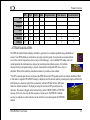
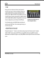
EFIS-D6
Electronic Flight Information System
Pilot’s User Guide
P/N 101208-000, Revision A
For use with firmware version 1.0
May, 2009
Dynon Avionics, Inc.
This product is not approved for
installation in type certificated aircraft
Contact Information
Dynon Avionics, Inc.
19825 141st Place NE
Woodinville, WA 98072
Phone: (425) 402-0433 - 7:00 AM – 5:00 PM (Pacific Time) Monday - Friday
Fax: (425) 984-1751
Dynon Avionics offers online sales, extensive support, and continually-updated information on its products via its Internet sites:
• www.dynonavionics.com –Dynon Avionics primary web site; including:
• docs.dynonavionics.com – Current and archival documentation.
• downloads.dynonavionics.com – Software downloads.
• support.dynonavionics.com – Support resources.
• store.dynonavionics.com – Dynon’s secure online store for purchasing all Dynon products 24 hours a day.
• wiki.dynonavionics.com – Dynon Avionics’ Documentation Wiki provides enhanced, extended, continuously-updated online documentation
contributed by Dynon employees and customers.
• forum.dynonavionics.com – Dynon Avionics’ Internet forum where Dynon customers can interact and receive Dynon technical support
outside of telephone support hours. A key feature of the forum is that it allows the exchange of diagrams, photos, and other types of files.
• newsletter.dynonavionics.com – Dynon’s email newsletter.
• blog.dynonavionics.com – Dynon’s blog where you can find new and interesting Dynon-related content.
Copyright
© 2003-2009 Dynon Avionics, Inc. All rights reserved. No part of this manual may be reproduced, copied, transmitted, disseminated or stored in any
storage medium, for any purpose without the express written permission of Dynon Avionics. Dynon Avionics hereby grants permission to download a
single copy of this manual and of any revision to this manual onto a hard drive or other electronic storage medium to be viewed for personal use,
provided that such electronic or printed copy of this manual or revision must contain the complete text of this copyright notice and provided further
that any unauthorized commercial distribution of this manual or any revision hereto is strictly prohibited.
Information in this document is subject to change without notice. Dynon Avionics reserves the right to change or improve its products and to make
changes in the content without obligation to notify any person or organization of such changes. Visit the Dynon Avionics website
(www.dynonavionics.com) for current updates and supplemental information concerning the use and operation of this and other Dynon Avionics
products.
Limited Warranty
Dynon Avionics warrants this product to be free from defects in materials and workmanship for three years from date of shipment. Dynon Avionics
will, at its sole option, repair or replace any components that fail in normal use. Such repairs or replacement will be made at no charge to the customer
for parts or labor. The customer is, however, responsible for any transportation cost. This warranty does not cover failures due to abuse, misuse,
accident, improper installation or unauthorized alteration or repairs.
THE WARRANTIES AND REMEDIES CONTAINED HEREIN ARE EXCLUSIVE, AND IN LIEU OF ALL OTHER WARRANTIES
EXPRESSED OR IMPLIED, INCLUDING ANY LIABILITY ARISING UNDER WARRANTY OF MERCHANTABILITY OR FITNESS FOR A
PARTICULAR PURPOSE, STATUTORY OR OTHERWISE. THIS WARRANTY GIVES YOU SPECIFIC LEGAL RIGHTS, WHICH MAY
VARY FROM STATE TO STATE.
IN NO EVENT SHALL DYNON AVIONICS BE LIABLE FOR ANY INCIDENTAL, SPECIAL, INDIRECT OR CONSEQUENTIAL DAMAGES,
WHETHER RESULTING FROM THE USE, MISUSE OR INABILITY TO USE THIS PRODUCT OR FROM DEFECTS IN THE PRODUCT.
SOME STATES DO NOT ALLOW THE EXCLUSION OF INCIDENTAL OR CONSEQUENTIAL DAMAGES, SO THE ABOVE LIMITATIONS
MAY NOT APPLY TO YOU.
Dynon Avionics retains the exclusive right to repair or replace the instrument or firmware or offer a full refund of the purchase price at its sole
discretion. SUCH REMEDY SHALL BE YOUR SOLE AND EXCLUSIVE REMEDY FOR ANY BREACH OF WARRANTY.
These instruments are not intended for use in type certificated aircraft at this time. Dynon Avionics makes no claim as to the suitability of its products
in connection with FAR 91.205.
Dynon Avionics’ products incorporate a variety of precise, calibrated electronics. Except for replacing the optional internal backup battery in EFISbased products per the installation guide, our products do not contain any field/user-serviceable parts. Units that have been found to have been taken
apart may not be eligible for repair under warranty. Additionally, once a Dynon Avionics unit is opened up, it will require calibration and verification
at our Woodinville, WA offices before it can be considered airworthy.
EFIS-D6 Pilot’s User Guide
iii
Table of Contents
Contact Information..............................................................................................................................................................ii
Copyright..............................................................................................................................................................................ii
Limited Warranty ................................................................................................................................................................iii
1. Introduction
1-1
Before You Fly ..................................................................................................................................................................1-1
Warning .............................................................................................................................................................................1-1
About this Guide................................................................................................................................................................1-1
2. Product Overview
2-1
EFIS-D6 Hardware ............................................................................................................................................................2-1
ADAHRS Operation..........................................................................................................................................................2-2
3. Product Operation
3-1
Front Panel Layout ............................................................................................................................................................3-1
Display...............................................................................................................................................................................3-2
Menus ................................................................................................................................................................................3-2
4. Display Elements
4-1
Horizon line, pitch and roll indicators ...............................................................................................................................4-1
Stabilized heading tape and digital readout .......................................................................................................................4-2
Turn rate indicator .............................................................................................................................................................4-2
Altitude tape, digital readout, and VSI ..............................................................................................................................4-3
Angle of attack (AOA) indicator .......................................................................................................................................4-3
EFIS-D6 Pilot’s User Guide
v
Table of Contents
Airspeed tape, digital readout, and trend .......................................................................................................................... 4-4
Slip/skid ball ..................................................................................................................................................................... 4-5
Altimeter setting display................................................................................................................................................... 4-5
5. Operation
5-1
POWER – Power on/off ................................................................................................................................................... 5-1
BARO – Changing Altimeter Setting ............................................................................................................................... 5-1
SETUP – Setting Preferences ........................................................................................................................................... 5-2
6. Alerts
6-1
Alarm Indicators ............................................................................................................................................................... 6-1
7. Appendix
7-1
Appendix A: PC Support Program ................................................................................................................................... 7-1
Appendix B: Troubleshooting .......................................................................................................................................... 7-1
Appendix C: EFIS-D6 Specifications............................................................................................................................... 7-5
vi
EFIS-D6 Pilot’s User Guide
1. INTRODUCTION
Thank you for purchasing the Dynon Avionics EFIS-D6. This section provides some important cautionary information
and general usage instructions for this manual.
Before You Fly
We strongly recommended that you read this entire guide before attempting to use the EFIS-D6 in an actual flying
situation. Additionally, we encourage you to spend time on the ground familiarizing yourself with the operation of the
product. While first learning to use the instrument in the air, we recommend you have a backup pilot with you in the
aircraft. Finally, we encourage you to keep this manual in the aircraft with you at all times. This document is designed to
give you quick access to information that might be needed in flight. CAUTION: in a flying situation, it is the pilot’s
responsibility to use the product and the guide prudently.
Warning
Dynon Avionics’ products incorporate a variety of precise, calibrated electronics. Except for replacing the optional
internal backup battery in EFIS-based products per the installation guide, our products do not contain any field/userserviceable parts. Units that have been found to have been taken apart may not be eligible for repair under warranty.
Additionally, once a Dynon Avionics unit is opened up, it will require calibration and verification at our Woodinville,
WA offices before it can be considered airworthy.
About this Guide
This guide serves two purposes. The first is to help you configure and get acquainted with the EFIS-D6’s many
functions. The second is to give you quick access to vital information. For detailed technical and installation information,
please refer to the EFIS-D6 Installation Guide.
EFIS-D6 Pilot’s User Guide
1-1
Introduction
In the electronic (.PDF) version of this manual, page and section references in the Table of Contents and elsewhere act as
hyperlinks taking you to the relevant location in the manual. The latest version of this manual may be downloaded from
our website at docs.dynonavionics.com.
This guide discusses the most common operation scenarios. If you have an operational issue that is not discussed in this
guide, you can find additional operational information on Dynon’s Internet sites:
• wiki.dynonavionics.com – Dynon’s Documentation Wiki provides enhanced, extended, frequently updated online
documentation contributed by Dynon employees and customers.
• forum.dynonavionics.com – Dynon’s Online Customer Forum is a resource for Dynon Avionics customers to
discuss installation and operational issues relating to Dynon Avionics products. The Forum is especially useful for
pilots with uncommon aircraft or unusual installation issues. For customers that cannot call Dynon Technical
Support during our normal business hours, the Forum is a convenient way to interact with Dynon Avionics
Technical Support. The Forum allows online sharing of wiring diagrams, photos, and other types of electronic files.
Any text following this icon refers to a setting or situation which merits particularly close attention.
1-2
EFIS-D6 Pilot’s User Guide
2. PRODUCT OVERVIEW
This section provides a general overview of the various parts of the EFIS-D6 as well as a theory of operation. The
information in this section serves as a reference only and helps familiarize you with the inner workings of the unit. It
should not be used for diagnostic or reparative work.
EFIS-D6 Hardware
The EFIS-D6 uses solid-state sensors to provide accurate and reliable information about your flying environment in an
easy-to-use interface.
POWER
The EFIS-D6 requires between 10 and 30 volts DC for operation. It is acceptable to have the EFIS-D6 turned on during
engine start.
The EFIS-D6 can be ordered with an optional internal battery which allows the instrument to continue to operate in the
event of an external power failure. This lithium-ion battery is rechargeable and is managed by the EFIS-D6. Under
normal conditions, the internal battery should have a voltage between 13 and 16.8 volts. When the battery’s voltage
drops below 13 volts, the EFIS-D6 displays a low battery warning. When new, a fully charged internal battery is rated
for a minimum of 2 hours of normal operation with the EFIS-D6. If the EFIS-D6 has switched to its internal emergency
battery due to a power loss in your aircraft, it is advised that you land as soon as possible.
SENSORS AND INPUTS
Attitude information is obtained from 3 solid-state gyrometers, 3 solid-state accelerometers, and the airspeed pressure
sensor. Heading information is obtained from 3 solid-state magnetometers housed in the EDC-D10A. Airspeed, altitude
and angle of attack are obtained from three separate pressure transducers.
EFIS-D6 Pilot’s User Guide
2-1
Product Overview
OUTPUTS
The EFIS-D6 has an output to drive an external customer-supplied audible device for AOA (if installed) and altitude
alerts.
A serial output is also provided for serial altitude encoder data. An optional Serial-to-Gray Code Converter is available
for connection to Mode C Gray Code transponders.
DISPLAY
The display is a 4-inch, 320 by 240 pixel, 450-nit LCD screen.
BUTTONS AND KNOBS
User interaction takes place via the six buttons along the bottom of the front panel of the unit.
ADAHRS Operation
The primary flight instruments on your EFIS display are generated using a group of calibrated sensors. All of them are
solid state – that is, there are no moving parts. These sensors include accelerometers, which measure forces in all three
directions; rotational rate sensors, which sense rotation about all three axes; pressure transducers for measuring air data;
and magnetometers on all three axes for measuring magnetic heading. These sensors form the core of Dynon’s Air Data
Attitude and Heading Reference System (ADAHRS).
The table below describes which inputs and sensors are used within the EFIS to generate the different displayed
instruments. It is not meant to enable in-flight troubleshooting, but is provided to convey how much of an integrated
system your EFIS is.
2-2
EFIS-D6 Pilot’s User Guide
Product Overview
Ball
Altitude
Airspeed
AOA
Turn Rate
Heading
Attitude
GPS
Pitot
Static
X*
X*
X*
X
X
X
X
X
X
X
X
X
X
X
AOA
Magnetometers
Rate Sensors
Accelerometers
X
X
X
X
X
X
X
X
X
ATTITUDE CALCULATION
The EFIS-D6 artificial horizon display (attitude) is generated via a complex algorithm using a multitude of
sensors. Your EFIS attitude is not reliant on any single external system. It can provide an accurate attitude even in the event of airspeed loss (due to icing or other blockage) - via a redundant GPS aiding source. In
normal operation the instrument uses airspeed to provide superior attitude accuracy. If a problem
develops with your airspeed reading, a properly connected and configured GPS source acts as a
substitute. When in this mode the instrument continues to provide accurate attitude.
*If a GPS is present upon the loss of airspeed, the EFIS-D6 uses the GPS ground speed in its attitude calculation. When
in this mode, a magenta GPS ASSIST message is displayed over the horizon and the ground speed is displayed below the
IAS indicator (as shown at right). If the connectivity with the GPS fails while in GPS assist
mode, the attitude continues to be displayed, using the last known GPS ground speed as a
reference. This mode is flagged on the horizon with a yellow CROSS CHECK ATTITUDE
message. In the very rare case that this sequence of event occurs, the EFIS-D6’s attitude
accuracy is reduced; use other references in the aircraft to cross-check against the EFIS-D6’s
attitude.
EFIS-D6 Pilot’s User Guide
2-3
3. PRODUCT OPERATION
After reading this section, you will be familiar with the basics of how to use your EFIS-D6. For details regarding specific
procedures (e.g., adjusting display brightness, changing the altimeter setting, etc.) please refer to the Operation section.
Front Panel Layout
All normal operation of the EFIS-D6 happens via the front panel. The
front panel contains buttons and a display.
• Buttons – There are six buttons on the front panel of the EFISD6. Throughout this guide, these buttons are referred to as one
through six, with button one being the leftmost and button six
being the rightmost. EFIS-D6 buttons are used to turn the
instrument on and off, scroll through menus, and adjust
instrument parameters.
• Display – The display shows EFIS information and menus.
1
2
3
4
5
6
User interaction takes place via the EFIS-D6
main display and the six buttons beneath.
EFIS-D6 Pilot’s User Guide
3-1
Product Operation
Display
The EFIS-D6 display is the most obvious and commonly used output of the device.
Menus
All interaction with the EFIS-D6 is accomplished through the use of its menu system. The menu system is accessed and
navigated via the six buttons located on the front of the unit. With no menu displayed, press any button to display the
main menu. With a menu displayed, pressing any one of these buttons performs the action – or enters the menu –
described by the label above it.
FUNCTIONALITY
A menu consists of two rows of gray boxes containing text. The upper row contains one tab that denotes the currently
displayed menu. The lower row contains six labels that denote the function of the button below it. Many of the onscreen
elements move up to avoid the menu. This prevents the menu from obscuring useful data while it is up. Upon exiting the
menu, the screen returns to its normal appearance.
Pressing a button either displays another menu or adjusts a parameter. If there is no text above a button, then that button
does not have a function in the context of that menu. Occasionally, a button label spans two or more buttons. In this case,
any button below the label invokes the command.
If a menu contains more options than there are buttons, the MORE label is displayed over button five. Pressing this
button shows you the next set of options in the current menu.
In any menu, press the BACK button to return to the previous menu and save any changes. In all top-level menus, button
six is the EXIT button. Pressing EXIT removes the menu system and moves many of the onscreen elements down to
their original positions.
3-2
EFIS-D6 Pilot’s User Guide
Product Operation
FLOW
Each page has its own main menu, which may contain options for
navigating to other menus or choosing and adjusting parameters. For
example, the EFIS SETUP menu contains button labels for PITCH,
UNITS, CLUTTR, MORE, and BACK. Pressing MORE reveals the rest
of the SETUP menu. That menu contains options for VRSION, IASCLR,
ALTENC, BARO, MORE, and BACK. Pressing MORE on the last menu
of the series simply returns you to the first part of the EFIS menu.
Each menu consists of labels above each
button denoting their function.
To exit the menu system, press the BACK button as many times as is
needed to reach an EXIT button. This varies based upon how deep you
are into the menu system.
DESCRIPTIONS IN THIS GUIDE
Throughout this guide, the “>” character is used to indicate entering a deeper level of the menu system. For example,
“SETUP > BARO” indicates entering the SETUP menu, pressing MORE, and then pressing BARO. Note that the
MORE button is not included in the sequence, since pressing MORE reveals more options in the same level of the menu
system.
EFIS-D6 Pilot’s User Guide
3-3
4. DISPLAY ELEMENTS
The EFIS main pages use various tapes, digital displays, and other
indicators overlaid on an artificial horizon.
Some of the displayed items described below may not be onscreen,
depending on whether or not they have been enabled in the SETUP >
CLUTTR menu.
The following sections provide detail on each onscreen display
element.
Horizon line, pitch and roll indicators
Bounded on the top by blue, and on the bottom by brown, the horizon
line behaves in much the same way as a traditional gyro-based artificial horizon. Unlike a
mechanical artificial horizon, the EFIS-D6’s horizon has no roll or pitch limitation. The horizon
line stays parallel to the Earth’s horizon line regardless of attitude. The parallel lines above and
below the horizon line are the pitch indicator lines, with each line indicating 5 degrees of pitch.
The end of each 10º pitch indicator line has a hooked barb that points towards the horizon line to
aid attitude awareness.
The roll scale has tic marks at 10, 20, 30, 45, 60, and 90 degrees of roll. In the CLUTTR menu
(described on page 5-3), you can choose between a stationary roll indicator and one that rotates
along with the horizon. The stationary roll indicator (type 1 in the SETUP > CLUTTR > ROLL menu) has an internal
arrow which moves to stay perpendicular to the horizon, like a jet EFIS presentation. The moving roll indicator (type 2)
rotates the scale about a stationary internal arrow which points to the current roll angle on the scale, like most
mechanical attitude instrument presentations.
EFIS-D6 Pilot’s User Guide
4-1
Display Elements
Stabilized heading tape and digital readout
Located at the top of the EFIS page, the heading indicator
functions much like a standard slaved directional gyro.
North, East, South, and West directions are labeled on the tape, “N,” “E,” “S,” and “W,” respectively. The digital readout
displays your current heading, while the surrounding tape scrolls beneath its arrow.
Like a conventional gyro-stabilized magnetic compass, magnetic heading reacts immediately to turn rate so that heading
changes are reflected immediately. It then uses magnetometer data over the long term to ensure that it remains correct.
Additionally, heading is corrected for attitude so that it is accurate as you pitch and roll.
Turn rate indicator
Centered just below the heading digital readout, the turn rate indicator displays the
aircraft’s current rate of turn with respect to the ground. The magenta bar grows in
the direction that the aircraft is currently turning, and is anchored at a white
vertical anchor line. The brackets on either side of the bar’s anchor line represent
the turn rate which results in a standard rate turn. Turn rate takes attitude into
account. This means that even when you are highly banked, it still shows rate of turn in relation to the aircraft’s heading.
The turn rate indicator is scaled to indicate a 6-second heading trend. In the example above, the trend indicator is
showing that the aircraft will be pointed at 40º in 6 seconds if the rate of turn does not change.
4-2
EFIS-D6 Pilot’s User Guide
Display Elements
Altitude tape, digital readout, and VSI
The altitude tape scrolls beneath the altitude digital readout and arrow. The digital readout’s digits scroll
up and down, simulating an analog altimeter and giving a sense of the direction of movement. Thousands
of feet are displayed using large numbers while hundreds of feet are displayed in smaller numbers. The
EFIS-D6 accurately displays altitudes from -1200 to 30,000 ft (-365 to 9144 m).
The graphical Vertical Speed Indicator is located next to the altitude tape. The magenta bar grows in the
direction of – and in proportion to – the rate of climb or descent. The numbers on the scale represent
thousands of feet per minute. In the CLUTTR menu, the VSI scale can be set to display 1000 ft/min, 2000
ft/min, and 4000 ft/min. The 2000 ft/min scale is linear throughout the range, while the 1000 ft/min and
4000 ft/min are non-linear as shown on the scale. When set to display 2000 ft/min, the VSI bar is scaled to
indicate a 6-second altitude trend based on its position with relation to the altitude bar. When set to display
4000 ft/min, the VSI bar is scaled to indicate a 6-second trend only up to 1000 ft/min. When set to display
1000 ft/min, the VSI bar is scaled to indicate a 12-second trend up to 500 ft/min.
During the first 30 seconds of operation, the altitude tape and digital readout are not displayed as the unit
needs a small amount of time before altitude measurements are deemed accurate.
Angle of attack (AOA) indicator
The angle of attack indicator – available only with Dynon’s AOA Pitot Probe – displays the aircraft’s current
AOA relative to the stall AOA. The AOA calibration process should result in the lowest angle of attack stall
(usually the “clean” configuration) occurring between the yellow and red lines and the higher angle-of-attack stall
(usually the “dirty” configuration) occurring at the top of the red. As your aircraft’s angle of attack increases, the
bars in the indicator disappear, leaving the empty outline. As your aircraft’s AOA approaches stall, downwardpointing arrows are left. Depending on your installation and configuration, an audible alarm may also occur when
EFIS-D6 Pilot’s User Guide
4-3
Display Elements
near or in the stall. This audio alarm is accompanied by a flashing red triangle at the top of the AOA display. To judge
when a stall will occur, remember that the AOA indicator is showing actual AOA, and the stall AOA changes with
configuration. Because of this, a stall could occur anywhere inside the yellow range, but will occur at the same point
every time given a specific configuration. Refer to the EFIS-D6 Installation Guide for more information on calibrating
the AOA indicator.
Airspeed tape, digital readout, and trend
The airspeed tape scrolls beneath the airspeed digital readout and arrow. The digital readout’s digits scroll
up and down, simulating an analog airspeed indicator and giving a sense of the increase or decrease in
speed. The EFIS-D6 is factory-calibrated to be accurate for airspeeds between 15 and 325 knots (17 to 374
mph). As airspeed increases from 0 knots, the indicator becomes active at 20 knots. The indicator remains
active until airspeed drops below 15 knots. The EFIS-D6 may display airspeeds above 325 knots, but it is
not guaranteed to be accurate.
The airspeed tape utilizes 4 colors to give you a graphical representation of your speed with relation to your
aircraft’s limits. By default all of the color thresholds are set at 0, causing a grey tape to be displayed. You
must set the values of the airspeed color thresholds via the SETUP menu. Refer to the EFIS-D6 Installation
Guide for more information on setting the airspeed color thresholds.
The airspeed trend indicator is located to the left of the airspeed tape. The magenta bar grows in the
direction of—and in proportion to—the rate of acceleration or deceleration. The trend indicator is scaled to indicate a 6second airspeed trend. In the example at right, the trend indicator is showing that the aircraft will reach 119 knots in 6
seconds if acceleration does not change.
4-4
EFIS-D6 Pilot’s User Guide
Display Elements
Slip/skid ball
The slip/skid ball works much like a standard mechanical gauge. It is a visual representation of lateral
acceleration. If the ball is within the two vertical lines, then you are in coordinated flight.
Altimeter setting display
The current altimeter setting is displayed at the bottom right of the screen below the altitude tape. The value
is shown in either inches of Mercury or millibars depending on your preference set in the BARO menu.
EFIS-D6 Pilot’s User Guide
4-5
5. OPERATION
This section guides you through each of the EFIS main page menu selections and their sub-menus. To enter the EFIS
menu system, press any button.
POWER – Power on/off
When the EFIS-D6 is turned off but still has a power source via Master switch power, Emergency backup power, or
Internal battery, press Button 1 to turn the unit on. Likewise, once the unit is on and no menus are displayed, push and
hold the leftmost button to turn it off. While power is still connected, the unit is never fully turned off. It simply enters an
extremely low-power state (except when the backup battery is discharged; in that case the EFIS will charge the battery
then return to the low-power state). It is acceptable to have the EFIS-D6 on during engine crank. It immediately powers
on upon application of external power.
BARO – Changing Altimeter Setting
In the EFIS > BARO menu, you can adjust the altimeter
setting. When the BARO menu is displayed, the valuesetting box shows the current altimeter setting. The DECand INC+ buttons change the altimeter setting by 1/100th
inHg or 1 mbar, depending upon your selected units. As you change the altimeter setting, the altitude indicators change
accordingly. Adjust the altimeter setting until the altitude indicators display the correct altitude for your location or the
altimeter setting matches the current barometric pressure value.
The altimeter setting can be set in units of inches of mercury (inHg) or millibars (mb). To change the units, simply press
buttons 1 or 2, corresponding to the UNITS label. To reset the altimeter setting to standard day pressure (29.92 inHg),
press button 3, corresponding to 29.92 (inHg) or 1013 (mb).
EFIS-D6 Pilot’s User Guide
5-1
Operation
The current indicated altitude is preserved across a power cycle. When powered down, the instrument saves the indicated
altitude. When it is powered up again, the instrument automatically adjusts the altimeter setting by exactly enough to
preserve that saved value. This is not a replacement for modifying the altimeter setting by the pilot before takeoff; it
makes it very close to the correct value, minimizing the amount of adjustment needed. To turn auto-set on or off, enter
the SETUP > BARO menu and set the ADJUST AT BOOT option to ON or OFF.
SETUP – Setting Preferences
Enter the SETUP menu to make changes to preferences. Many of the settings in this menu should only be changed by the
installer, and are described in the EFIS-D6 Installation Guide. The preferences and settings that are relevant to the pilot
and in-flight operation are explained below.
CHANGE DISPLAYED UNITS
In the UNITS submenu, you may change the system-wide
displayed units for the following units. See the
Parameter
following table for a list of available units for
Airspeed (IAS)
each displayed parameter.
Altitude (ALT)
Barometric Pressure (BARO)
5-2
Available units
Knots, miles/hour, kilometers/hour
Feet, meters
inHg, mbar
EFIS-D6 Pilot’s User Guide
Operation
SHOW/HIDE DISPLAY ITEMS
In the SETUP > CLUTTR menu, you can turn on or off almost every item displayed on the EFIS page. As with all other
menu items, these options are abbreviated to commands containing 6 letters or fewer. Pressing a button corresponding to
one of these options turns the respective onscreen item on or off. The following table summarizes the display item
abbreviations and their function.
Abbreviation
ALTBAR
ALTDIG
IASBAR
IASDIG
HDG
BALL
TURNRT
AOABAR
Display Item
Altimeter Bar
Altimeter Digital
Indicated Airspeed Bar
Indicated Airspeed Digital
Heading
Slip/skid Ball
Turn Rate
AOA Bar
ASTRND
BARO
Airspeed Trend
Altimeter Setting
ROLL
Roll Scale
EFIS-D6 Pilot’s User Guide
Function
Toggles the display of the graphical altitude tape.
Toggles the display of the digital altitude window.
Toggles the display of the graphical airspeed tape.
Toggles the display of the digital airspeed window.
Toggles the display of the heading tape and digital display.
Toggles the display of the slip/skid ball and associated center markers.
Toggles the display of the turn rate indicator and associated scale markers.
Toggles the display of the angle of attack indicator. The AOA indicator requires the
use of a Dynon heated or unheated AOA probe.
Toggles the display of the 6-second airspeed trend indicator next to the IAS tape.
Toggles the display of the current altimeter setting (also known as the Kollsman
setting). This display is not required to adjust the altimeter setting. While in the
EFIS > BARO menu, a separate value-setting box appears, allowing adjustments to
be made.
Toggles and configures the display of the roll scale. When set to “N”, the roll scale
is not displayed. When set to “1,” the roll scale stays fixed on the screen and the
pointer moves along the scale, like a jet EFIS presentation. When set to “2”, the roll
scale moves with the horizon, while the pointer stays fixed on the screen, like most
mechanical attitude instrument presentations.
5-3
Operation
Abbreviation
VSI
Display Item
Vertical Speed Indicator
VMETER
Voltmeter
Function
Toggles and configures the display of the VSI tape next to the altitude tape. The
VSI can be hidden (“N”), or can be set to 1k, 2k, or 4k ft/min scaling. The 2000
ft/min display is linear throughout the range, while the 1000 and 4000 ft/min
displays incorporate a non-linear scale to increase low vertical speed resolution.
Toggles the display of the Voltmeter, displaying the voltage of the Master power,
External Backup power input, and the Internal battery, respectively.
CHECK FIRMWARE VERSION
The SETUP > VRSION menu gives you two important pieces of information: your EFIS-D6’s current firmware version;
and the number of hours the EFIS-D6 has been on. If you require technical support or other assistance from Dynon,
please have your firmware version ready when you call or write.
VOLTMETER DISPLAY
The voltmeter displays 3 rows of information corresponding to the three power inputs on the EFISD6. The first row, labeled M, displays the Master Switch voltage. The second row, labeled E,
displays your optional external backup voltage. The third row, labeled I, displays the EFIS-D6
internal battery voltage. If any of the 3 voltage inputs are not present, 00.0V is displayed for the
respective voltage values. The letter V follows all three values, denoting the fact that voltages are being displayed. The
EFIS-D6 alerts you when the internal battery is low by displaying a low battery alert.
DIM – CHANGING SCREEN BRIGHTNESS
In the DIM menu, press BRITR or DRKR to change the brightness of the display. It is not possible to turn the screen
completely black. Note that if power to the EFIS-D6 is cycled, the screen is reset to full brightness.
5-4
EFIS-D6 Pilot’s User Guide
6. ALERTS
Alarm Indicators
Any time a built-in or preconfigured alarm set point is exceeded, you are alerted to the fact via the alarm bar and menu at
the bottom of the screen.
When an alarm is triggered, the following things occur:
• A red alarm bar appears at the bottom of the screen with a message identifying the out of range measurement
• Below the alarm bar, the alarm menu gives you options for what to do next. See the following subsections for
more information
Note that alarms may not be acknowledged during the initial two seconds of the first alarm.
In an alarm condition, the EFIS-D6 does not alert you audibly. The audio out connection on the EFIS-D6 is for AOA
alerts only.
ALARM ACKNOWLEDGEMENT
To acknowledge the alarm, press the ACK button. The ACK button has a number next to it indicating the number of
currently posted alarms. If this number is higher than 1, after you press ACK, you will see the alarm text for the next
posted alarm. Pressing ACK does the following:
• Removes the alarm bar and alarm menu (if no other alarms are stacked up), and brings up the previous menu.
• Stops the blinking of the relevant display
The tic and numeric value remain red until the condition no longer exists. The alarm automatically rearms whenever the
alarm condition is removed.
EFIS-D6 Pilot’s User Guide
6-1
7. APPENDIX
This appendix contains information not covered in the main section of the manual. This section contains reference tools
such as a detailed description of the serial data format output by the EFIS-D6, a specifications sheet, and a
troubleshooting guide. This section also contains details regarding EFIS-D6 servicing.
Appendix A: PC Support Program
Dynon offers a free PC Support Program which allows you to upload new firmware and checklists. The latest version of
this program is available from the Dynon Avionics website at downloads.dynonavionics.com.
Appendix B: Troubleshooting
See the EFIS-D6 Installation Guide Appendix for a variety of troubleshooting tips and solutions.
Additional troubleshooting information can be found on Dynon Avionics’ Internet sites:
•
wiki.dynonavionics.com – Dynon’s Documentation Wiki provides enhanced, extended, continuously-updated online
documentation contributed by Dynon employees and customers.
•
forum.dynonavionics.com – Dynon’s Online Customer Forum is a resource for Dynon Avionics customers to
discuss installation and operational issues relating to Dynon Avionics products. The Forum is especially useful for
pilots with uncommon aircraft or unusual installation issues. For customers that cannot call Dynon Technical
Support during our normal business hours, the Forum is a convenient way to interact with Dynon Avionics
Technical Support. The Forum allows online sharing of wiring diagrams, photos, and other types of electronic files.
Should you experience difficulty with your product that is not solved by reading the troubleshooting section or
information in the wiki or forum, please call Dynon Technical Support at (425) 402-0433 7:00 AM - 5:00 PM (Pacific
EFIS-D6 Pilot’s User Guide
7-1
Appendix
Time) Monday - Friday or email us at [email protected]. Be sure to have the EFIS-D6’s firmware version
number ready when you contact us. To locate your product’s firmware version, refer to the Check firmware version
section on page 5-4.
DISPLAYED ALERT MESSAGES
The following table describes the alert messages that the EFIS-D6 can display.
Alert Message
INTERNAL ERROR
SERVICE UNIT
Description
This error can occur for a few reasons, including
an aborted upload. It signifies that the EFIS-D6
has detected internal problems in its firmware or
calibration tables.
ATTITUDE
RECOVERING…
This alert is displayed anytime the unit is rotated
at a rate faster than 150 degrees/second or the unit
is powered on with airspeed applied. Rotating the
unit faster than this threshold will saturate the
gyros, leading to potentially erroneous display.
The blue/brown horizon indication will turn grey
and black to indicate that the artificial horizon is
not currently a trusted source. Note that this alert
only appears when airspeed is non-zero; using the
EFIS-D6 on the bench will not trigger this alert.
7-2
End condition
When this error appears, it may be possible to
recover your unit in the field. The best way of
ensuring this is to call Dynon Avionics
immediately. However, there is a good
possibility that the unit will have to be returned
for service.
The grey/black horizon indication and onscreen
message will remain until the unit has resumed
normal operation. In the case of rotation rate
greater than 150 degrees/second, the unit enters
a fast recovery mode and usually recovers
within 5 seconds of coordinated flight.
EFIS-D6 Pilot’s User Guide
Appendix
Alert Message
TEMPERATURE
UNSTABLE
Description
When the unit is turned on after having been off
for a long period, its internal temperature will rise
above ambient at a fast rate. This fast change in
temperature can sometimes reduce the reliability
of the output of the sensors. Therefore, this alert
is displayed and the horizon indication is changed
from blue/brown to grey/black.
TEMPERATURE OUT
OF SPEC
The temperature inside the unit is outside of
-30ºC to 50ºC.
INTERNAL BATTERY
LOW
You will see this alert only when operating the
unit solely off the internal backup battery. When
its voltage has dropped below a certain threshold,
you will see this alert. Additionally, the voltmeter
will be displayed onscreen. When you see this
alert, it is advisable that you turn the unit off by
pressing the POWER button in Main Menu 1.
EFIS-D6 Pilot’s User Guide
End condition
The screen remains normal color, but the
message is displayed until the temperature
within the unit has stabilized. This temperature
instability should last no longer than 2 minutes.
For this reason, it is a good idea to turn the unit
on before you run through any of the preflight
procedures, so that it will be ready by the time
you are ready to fly.
The screen remains normal color, but the
message is displayed until the temperature
within the unit is within the specified range.
This is most common in unventilated panels
during hot periods. If you continue to see this
alert, provide more airflow to the space around
the EFIS-D6.
The alert will disappear when you press any
button; however, it is advised that you do not
ignore this alert, as it appears when the unit’s
internal battery has very little life left. This alert
will also go away upon the application of either
the external backup battery or Master Power. At
that point, the battery will begin charging off the
external power.
7-3
Appendix
Alert Message
REMOTE COMPASS
NOT DETECTED
7-4
Description
The EFIS-D6 is unable to communicate with the
EDC-D10A. If you have an OAT connected to
your EDC-D10A, you will lose this reading, as
well.
End condition
Ensure that you a) have an EDC-D10A installed
and b) have verified that the wiring to the EDCD10A is correct. Please see the EFIS-D6
Installation Guide for more information on
verifying the installation of the EDC-D10A.
This error also can appear if you have updated
the firmware in your EFIS-D6 while the remote
compass was not connected. If this is the case,
try uploading the new firmware again with the
EDC-D10A connected. Attempt the connection
within the first few seconds of operation.
Note that the EFIS-D6 does not have internal
magnetic sensors and thus requires the EDCD10A be connected.
EFIS-D6 Pilot’s User Guide
Appendix
Appendix C: EFIS-D6 Specifications
Mounting:
Mechanical
Operating Temperature
Power
Connections
Screen
Inputs/Outputs
EFIS-D6 Pilot’s User Guide
Weight:
Fits into standard 3 1/8” panel hole
Optional flush mount bracket available
1 lb. 9 oz. (700 g)
1 lb. 15 oz. (880 g) with internal battery
-22° to 122° F (-30° to 50° C)
Voltage:
Power:
10 - 30 VDC
8 watts typical; 13 watts maximum
Wiring:
D-25 male
Type:
Backlight:
Size:
Resolution:
AMLCD, TFT (Thin Film Transistor)
450 nits
4.0” diagonal (101.6 mm)
320 x 240 color pixels
1 - Audio Alarm
1 - RS-232 bidirectional PC communication
1 - RS-232 data input (GPS for airspeed failover)
7-5


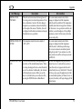
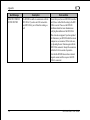
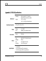


![U.S. Version [Last Updated on: Jun 13th, 2014]](http://vs1.manualzilla.com/store/data/005873845_1-0370c7761d3b42576ec2ae1fd24c9e75-150x150.png)
