1
2104
Chromalox
®
Temperature Controller
C
Issue Date
September 2006
Technical Manual
0037-75276
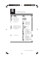
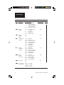
Table of Contents
Sections
Section
Topic
1
Getting Started ..................................................... 1
2
Installation ........................................................... 3
3
Operation ............................................................. 21
4
Controller Setup Pages ........................................ 33
5
Ramp/Soak Operation ......................................... 41
6
Alarms ................................................................. 47
7
Digital Input and AUX Function ......................... 59
8
Remote Setpoint & Analog Process Output ........ 67
9
Digital Communications...................................... 71
10
Calibration ........................................................... 75
11
Specifications ...................................................... 83
12
Troubleshooting ................................................... 87
13
Warranty and Return............................................ 89
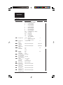
Page
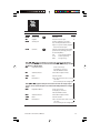
Appendices
I
Setup Pages.......................................................... 91
Menu Index
Index .............................................................................................. 103
Chromalox 2104 Technical Manual
i
Illustrations
Figure
Topic
1.1
1.2
Application ............................................................. 1
Model Identification............................................... 2
2.1
2.2
2.3
Sensor Selection Dip Switch Settings ................... 3
Mounting Dimensions ............................................ 5
Mounting Diagram ................................................. 5
2.4
2.5
2.6
Wiring Terminal Identification .............................. 7
Thermocouple Connections................................... 8
3-Wire RTD Connections ...................................... 9
2.7
2.8
2.9
2-Wire Connections ............................................... 9
Current Input Wiring (Self-powered) .................... 9
Voltage Input Wiring .............................................. 10
2.10
2.11
2.12
Current Input Wiring (Loop-power) ..................... 10
Event Input Connections External Switch............ 10
Momentary Contact Pushbutton for Ramp/Soak .. 10
2.13
2.14
2.15
Relay Output Connections .................................... 11
SSR Drive Output Jumper Positions ...................... 12
Solid State Relay Drive Output Connections ....... 13
2.16
2.17
2.18
Current/Voltage Output Jumper Positions ............. 14
Triac Output Connections ..................................... 15
4-20mA Analog Output Connections ................... 15
2.19
2.20
2.21
1-5 Vdc Output Connections ................................ 15
Dual Relay Output Wiring ..................................... 16
Dual Triac Output Wiring ...................................... 16
2.22
2.23
2.24
Dual Analog Output Wiring .................................. 16
Dual SSR Drive Output Wiring ............................. 16
Dual 1-5 Vdc Output Wiring ................................. 17
ii
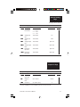
Page
Chromalox 2104 Technical Manual
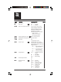
Illustrations
Figure
2.25
2.26
2.27
Topic
Page
Dual Output SSR/Relay Wiring ............................. 17
Dual Output SSR/Triac Wiring .............................. 17
Dual Output Analog/Relay Wiring ........................ 18
2.28
2.29
2.30
Dual Output Analog/Triac Wiring ......................... 18
100-240 Vac Instrument Power Connections ........ 19
12-24 Vac/Vdc Instrument Power Connections .... 19
2.31
2.32
Alarm/Event Outputs #3 and #4 ............................ 19
Alarm/Event Output #5 ......................................... 20
3.1
3.2
3.3
Front Panel Identification ...................................... 22
PAGE/MENU Setup Structure .............................. 23
Sample of PAGE/MENU Table .............................. 25
3.4
3.5
Security Levels and PAGE/MENU Contents ........ 26
Security Codes and View/Adjust Levels ................ 27
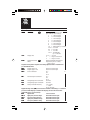
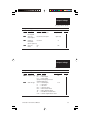
5.1
5.2
5.3
5.4
Ramp/Soak Profile .................................................. 41
Event Outputs in Ramp/Soak Profile ..................... 41
Looping Intervals .................................................... 42
Guaranteed Soak .................................................... 42
6.1
CLP Alarm Connections........................................ 55
8.1
8.2
8.3
Remote Setpoint Input Signal ............................... 67
2-Wire 4-20mA Transmitter (Loop-powered) ....... 68
2-Wire 4-20mA, 1-5 Vdc Transmitter (Self-powered) ... 68
8.4
8.5
8.6
3-Wire 4-20mA, 1-5 Vdc Transmitter ................... 68
Analog Process Output Signal ............................... 69
Process Output Wiring ........................................... 70
9.1
9.2
9.3
9.4
RS422/RS485 Communications Switches ............. 72
RS232 Wiring Connections ................................... 72
RS422A Wiring Connections (4-wire) ................. 73
RS485 Wiring Connections (2-wire)..................... 73
Chromalox 2104 Technical Manual
iii
iv
Chromalox 2104 Technical Manual
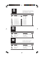
Section 1
Getting Started
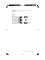
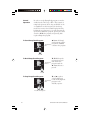
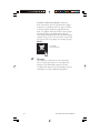
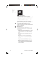
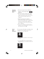
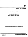
The Chromalox 2104 1/4 DIN temperature and
process controller is a low-cost, high-performance,
single-loop controller that can be used for
temperature, flow, pressure and level control
applications. With universal sensor inputs and front
panel operator setup, one 2104 controller can be easily
field configured for a wide variety of applications, and
simply reconfigured as application needs change. This
makes it an exceptional choice for OEMs with
multiple control needs, manufacturing facilities,
testing facilities and testing applications.
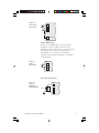
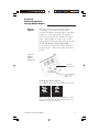
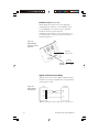
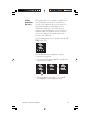
Figure 1.1
Typical Application
Shutdown
Contactor
Output #5
Control Loop
Protection
SCR
Heat
2104
2104
Recorder
Output #1
Cool
Output #2
Computer
ChromaSoft™
High Alarm-Output #3
Shutdown
RS485
Digital
Com.
Low Alarm-Output #4
Process
SCR
Heat
2104
Output #1
2104
Cool
Remote/Local
Setpoint Switch
Output #2
High Alarm-Output #3
Shutdown
Low Alarm-Output #4
Remote Setpoint
from DCS
Chromalox 2104 Technical Manual
1
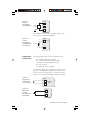
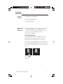
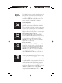
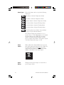
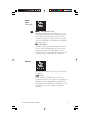
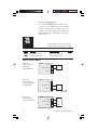
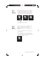
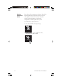
Model Identification
Before installation, please identify your controller model number. The model
number is written on the tag on the side of the housing.
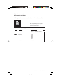
Figure 1.2 Model Identification
Model
Temperature Controller
2104
Microprocessor-based 1/4 DIN Temperature Controller. Universal Sensor Input
accepts Thermocouple, RTD, Current or Voltage Inputs. PID, ON/OFF with
Fuzzy Logic Control Capability. One Digital Input and Analog Remote Set Point.
Code
Outputs #1—Single Output Control
RO
Output #1 Single Output Control Relay/SSR Drive (jumper selectable)
Relay—N.O. Form A Contact, 1A at 120 or 230 Vac
SSR Drive—24Vdc at 40mA
Triac—1 Amp at 120 or 230 Vac
Analog—4-20mA or 1-5 Vdc, non-isolated
TO
AO
Outputs #1 & #2 - Heat/Cool Control
RR
TT
AA
SS
AR
AT
SR
ST
Relay/Relay
Triac/Triac
Analog/Analog
SSR Drive/SSR Drive
Analog/Relay
Analog/Triac
SSR Drive/Relay
SSR Drive/Triac
Code
Outputs #3 & #4 (Alarm/Event Outputs)
0
1
None
Dual Relay—Two (2) Form A contacts, 1A at 120 or
230 Vac with shared common terminal
Code
Isolated Digital Communications,
Output #5 (Alarm/Event Output),
and Analog Output Option
0
1
None
RS-422/485 Digital Communications and
Output #5
RS-232 Digital Communications and
Output #5
Analog Output Option
RS-422/485 Digital Communications,
Output #5 and Analog Output Option
RS-232 Digital Communications,
Output #5 and Analog Output Option
2
3
4
5
21042
RO
1
1
Code
Power Supply
0
1
100 - 240 Vac or Vdc
12-24 Vdc or Vac
0
Typical Model Number
Chromalox 2104 Technical Manual
Section 2
Installation
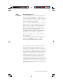
Inspection
and
Unpacking
On receipt of your 2104 controller, immediately make
note of any visible damage to the shipment packaging
and record this damage on the shipping documents.
Unpack the controller and carefully inspect it for
obvious damage due to shipment. If any damage has
occurred, YOU must file a claim with the transporter,
as they will not accept a claim from the shipper.
If the controller will not be immediately installed and
placed into operation, it should be stored in a cool, dry
environment in its original protective packaging until
time for installation and operation. Temperature
extremes and excessive moisture can damage the
instrument.
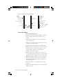
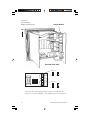
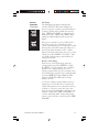
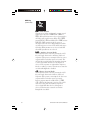
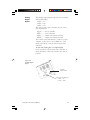
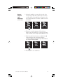
Switch
Settings
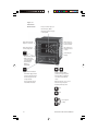
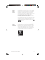
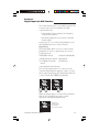
The 2104 has up to seven (7) hardware switches
located on the bottom of the controller. The switches
are accessible through cutouts in the controller
housing and do not require that you remove the
controller from its housing to access the switches.
Figure 2.1 identifies the switches. Instructions for
switch settings are given in the corresponding sections
of the manual.
Figure 2.1
Sensor Selection
Dip Switch
Settings
Switches #1 and #2
Digital Communications
RS422/RS485
Controller
Bottom Surface
Switches #1, #2 and #3
Sensor Input
Chromalox 2104 Technical Manual
Switch #4
Remote Setpoint
Input Signal
Switch #5
Analog Output
Signal
3
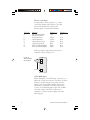
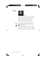
Sensor
Selection
Switches
Sensor selection requires that you:
1. Set the sensor switches for the correct sensor
type.
2. Program the input sensor type in sensor
selection setup on the INPT Page (see page 36).
It is much easier to set the sensor input switches
before you mount and wire the controller.
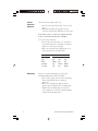
To set the sensor switches:
1. Locate the sensor switches—#1, #2 and #3—
on the bottom of the controller, as shown in
Figure 2.1 on the previous page.
2. Place the switches in the appropriate Up or
Down position for your input type:
Input Type
T/C
RTD
4-20mA
1-5 Vdc
Mounting
4
Switch #
1
2
Up
Up
Down Up
Up
Down
Up
Up
3
Up
Up
Down
Down
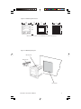
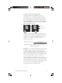
Figure 2.2, on the following page, shows the
mounting dimensions for the controller:
1. Cut out the square “panel cutout” mounting
hole and install the unit as shown in
Figure 2.3.
2. Place the controller through the square
panel cutout and replace the mounting clip.
3. Tighten the mounting clip screw (do not
over- tighten) to secure the controller firmly
against the mounting surface.
Chromalox 2104 Technical Manual
Figure 2.2 Mounting Dimensions
3.8
(96)
0.8
(19)
3.8
(96)
4.0
(102)
3.6
(92)
3.6
(92)
3.5
(90)
Measurements are shown in inches. Millimeters are shown in parentheses.
Figure 2.3 Mounting Diagram
Mounting Hole
Mounting Clip
Mounting Tab
Panel Cutout
Chromalox 2104 Technical Manual
5
Wiring
Instructions
Good Wiring Practices
1. When planning the system wiring, separate wiring
into functionally similar bundles - i.e., power leads,
sensor leads, output signal lines, etc. If the power leads
and sensor leads must cross, they should cross at a 90°
angle to each other (perpendicular).
2. Locate all sources of electrical noise in your system,
and separate these sources from the control systems—
motors, contacts, solenoids, etc. Electrical noise can
affect the function of any control system. When
driving a contactor coil or other inductive load, an
appropriately rated AC snubber circuit is
recommended (Chromalox Part. No. 0149-01305), as
described on page 11, “Relay Output Wiring.”
3. For sensor wiring practices, see Sensor Wiring
Notes, next page.
4. Additional information on good wiring practices is
available from IEEE, 345 East 47th St., NY, NY
10017. Request IEEE Standard No. 518-1982.
Make all electrical wiring connections to the back of
the controller before power is applied to the unit.
All wiring must comply with local codes, regulations
and ordinances. This instrument is intended for panel
mounting and the terminals must be enclosed within
a panel. Use National Electric Code (NEC) Class 1
wiring for all terminals except the sensor terminals.
Check the wiring decal on the side of the unit to
verify the model number. The wiring decal shows the
wiring terminations. All wires will be connected to the
terminals on the back of the instrument case. Specific
wiring instructions for different input and output types
are given in this section.
6
Chromalox 2104 Technical Manual
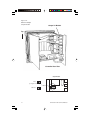
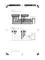
Figure 2.4 Wiring Terminal Identification
Digital
Input
Common
1
19
2
20
10
11
Digital
Communications
+24 Vdc Output
3
21
Analog Output
4
22
13
Remote Setpoint Input
5
23
14
Common
6
24
7
25
8
26
Output #1
and #2
12
Output #3 Relay
Sensor Input
9
27
RTD
Not Used
Output #5
15
Output #4 Relay
16
100/240 Vac or
12/24 Vac/Vdc
17
AC Common
18
Shield Ground
Instrument
Power
TC 4-20mA
Sensor Input Wiring
Sensor Input Wiring Notes:
• Sensor leads (thermocouple and RTD) should not
be run together in the same conduit as power
wiring.
• Twisted pair, shielded wire is recommended for
sensor connections.
• False process readings can occur if the sensor wire
is exposed to electrical noise.
• Ungrounded thermocouples are recommended.
• If thermocouple extension wire is required, it must
be the same type as the thermocouple (i.e., if a
Type K thermocouple is used, then Type K
extension wire must be used).
• Thermocouple wires should connect directly to
the controller terminals. Do not use copper crimp
terminals or solder terminals to make connections.
• If shielded thermocouple wire is used, the shield
must be grounded at one end only, preferably at
the shield ground terminal on the controller, as
shown in Figure 2.5.
• Three wire RTDs are recommended for greatest
accuracy.
• Standard shielded copper wire is recommended for
RTD extensions.
Chromalox 2104 Technical Manual
7
Thermocouple Inputs
It is important to observe polarity (+, -) when
connecting thermocouple leadwires. The table
below shows ANSI color coding for the
thermocouples used with this instrument.
T/C Type
B
J
K
E
T
R
S
Material
Plat, 30% Rhodium/
Plat, 6% Rhodium
Iron/Constantan
Chromel/Alumel
Chromel/Constantan
Copper/Constantan
Plat, 13% Rhodium/Plat
Plat, 10% Rhodium/Plat
Polarity (+)
Gray
Polarity (-)
Red
White
Yellow
Purple
Blue
Black
Black
Red
Red
Red
Red
Red
Red
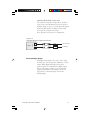
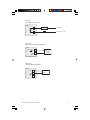
Make the thermocouple wiring connections to
terminals as shown in Figure 2.5.
Figure 2.5
Thermocouple
Connections
+
2104
8
-
Shield Gnd
9
18
3-Wire RTD Inputs
When making the 3-wire RTD input connection, it is
important to make the resistance of all three extension
leadwires equal by using the same gauge and same
length of wire for optimum leadwire compensation.
Chromalox recommends 3-wire RTDs for greatest
accuracy, and standard shielded copper wire for RTD
extensions. Make 3-wire RTD connections to
terminals 7, 8 and 9 as shown in Figure 2.6 on the
following page.
8
Chromalox 2104 Technical Manual
Figure 2.6
3-Wire RTD
Connections
2104
7
8
9
18
Shield Grnd
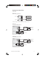
2-Wire RTD Inputs
If using a 2-wire RTD input, use heavier gauge
leadwires to reduce leadwire resistance. Any
leadwire resistance adds directly to sensor resistance,
thus adding error to the process temperature
measurement. It is also necessary to jumper
terminals 8 and 9 on the instrument to complete a
2-wire hookup.
Figure 2.7
2-Wire
Connections
2104
7
8
9
Current/Voltage Inputs
Figure 2.8
Current
Input Wiring
(Self-powered)
+
4-20mA
2104
7
8
9
Chromalox 2104 Technical Manual
9
Figure 2.9
Voltage
Input Wiring
(Self-powered)
2104
+
7
1-5 Vdc
0-5 Vdc
8
9
The 2104 has a +24 Vdc power supply which can be
used to power a 4-20mA transmitter.
Figure 2.10
Current
Input Wiring
(Loop-powered
by controller)
2104
3 +24 Vdc
+
4-20mA
7
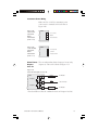
Digital Input
Connections
The digital input can be used in a number of ways:
• to control ramp/soak operations
• to switch between two setpoints, PID
parameters, or Auto/Manual control
• to reset an alarm
• to disable the control output.
Setup for the digital input is shown on the CTRl setup
page. An external switch, pushbutton or dry contact
can be connected to this input. Use isolated switches
only. Do not tie the Digital Input terminals to ground.
Figure 2.11
Digital Input
Connections
External Switch
2104
+
1
2
-
Figure 2.12
Momentary
Contact
Pushbutton for
Ramp/Soak
10
{ External
Input
2104
+
-
1
2
Chromalox 2104 Technical Manual
The 2104 is supplied with either:
• 1 Control Output for Single Output
Control (#1)
• 2 Control Outputs for Heat/Cool Control
(#1 and #2)
Output
Wiring
The output wiring varies depending on the control
type and applications. The wiring instructions are
presented separately for each of these two controller
types/applications.
☛
Warning
Incorrect output wiring may cause system/process
damage.
Single Output Control Wiring
Relay Output
Output Code “RO” on the 2104 (2104 - RO***)
gives you the option of SSR Drive or Relay control
for output #1. When shipped from the factory, the
relay output is active.
Figure 2.13
Relay Output Connections
10
Relay
Contacts
{
120 or 230 Vac
Internal
MOV
11
Load
AC Neutral
Snubber
SSR Drive Output
For SSR drive output applications, you must move
an internal jumper on the Output #1 module to
select SSR drive output. Remove the controller from
its housing, and locate the output module as shown
in Figure 2.14 on the following page. Reposition the
jumper to select SSR Drive output.
Chromalox 2104 Technical Manual
11
Figure 2.14
SSR Drive Output
Jumper Position
Output #1 Module
Top
Controller Rear View
Output Module
Relay
(as shipped from factory)
SSR Drive
12
Chromalox 2104 Technical Manual
Solid State Relay Drive Connections
The solid state relay drive output drives solid-state
relays, such as the Chromalox 4115 or 4117 power
modules, which accept 3 to 32 Vdc input ON signals
and 0 Vdc OFF signals. See Figure 2.15 for solid
state relay drive output connections.
Note: Negative lead connects to Terminal #2.
Figure 2.15
Solid State Relay Drive Output Connections
Output 1
{
12
2
+
-
Fuse
120 or 230 Vac
Load
AC Neutral
4115
Current/Voltage Output
Controllers with output codes “AO,” “AA,” “AR”
and “AT” give you the option of 4-20mA or 1-5 Vdc
output. When shipped from the factory, these
control outputs are configured for 4-20mA output.
For 1-5 Vdc output, you must access the internal
output board and move the jumper(s) to the 1-5
Vdc position, as shown in Figure 2.16 on the
following page.
Chromalox 2104 Technical Manual
13
Figure 2.16
Current/Voltage
Output Jumper Positions
Output Module
Top
Controller Rear View
Output #1*
4-20mA
1-5 Vdc
Output #2
4-20mA
1-5 Vdc
*All controllers with Analog Output (output codes AR, AT) for
output #1 use same 4-20mA/1-5 Vdc jumper positions as shown here.
14
Chromalox 2104 Technical Manual
Figure 2.17
Triac Output Connections
2104
Heat Load
10
AC Neutral
Fuse
11
120 Vac or 230 Vac
Figure 2.18
4-20mA Analog Output Connections
2104
+
10
+24 Vdc
4-20mA
11
-
Power
Controller
or Valve
(0-800 ohms)
Figure 2.19
1-5 Vdc Output Connections
2104
1-5 Vdc
10
11
+
Input
-
GND
12 NC
Chromalox 2104 Technical Manual
15
Heat/Cool Control
Output Wiring
Figure 2.20
Dual Relay Output Wiring
2104
10
Output #1
11
Heat
Load
AC Neutral
Fuse
120 Vac or 230 Vac
Output #2
12
Cool
Load
AC Neutral
10
Heat
Load
AC Neutral
Figure 2.21
Dual Triac Output Wiring
2104
Output #1
11
Fuse
120 Vac or 230 Vac
Output #2
12
Cool
Load
AC Neutral
Figure 2.22
Dual Analog Output Wiring
2104
10
+24 Vdc
Output #1
4-20mA
+
-
Heat Control
(0-800 Ohm)
11
-
Output #2
4-20mA
12
+24 Vdc
+
Cool Control
(0-800 Ohm)
Figure 2.23
Dual SSR Drive Output Wiring
Fuse
2104
+24 Vdc
10
(Output #1)
+
-
Solid
State
Relay
11
-
(Output #2)
+24 Vdc
16
12
+
Solid
State
Relay
120 Vac or 230 Vac
Heat
Load
Fuse
Cool
Load
AC Neutral
120 Vac or 230 Vac
AC Neutral
Chromalox 2104 Technical Manual
Heat/Cool Control Output Wiring
(continued)
Figure 2.24
Dual 1-5 Vdc Output Wiring*
Output #1
2104
1-5 Vdc
+
10
-
11
Output #2
1-5 Vdc
-
12
+
Input
GND
Heat
Control
GND
Input
Cool
Control
*Note: See page 14 for Analog/Voltage jumper positions.
Figure 2.25
Dual Output SSR/Relay Wiring
2104
-
-
2
Solid
State
Relay
Heat
Load
120 Vac or
230 Vac
AC Neutral
Fuse
11
(Output #2)
Fuse
+
10
(Output #1)
120 Vac or 230 Vac
MOV
12
Cool
Load
AC Neutral
Figure 2.26
Dual Output SSR/Triac Wiring
2104
(Output #1)
-
(Output #2)
Fuse
+
10
2
Solid
State
Relay
120 Vac or
230 Vac
Heat
Load
AC Neutral
Fuse
11
12
Chromalox 2104 Technical Manual
120 Vac or 230 Vac
Cool
Load
AC Neutral
17
Heat/Cool Control Output Wiring
(continued)
Figure 2.27
Dual Output Analog/Relay Wiring
2104
(Output #1)
4-20mA
+
10
-
Common
(Output #2)
2
11
Heater
Power
Controller
Fuse
120 Vac or 230 Vac
MOV
12
Cool
Load
AC Neutral
Figure 2.28
Dual Output Analog/Triac Wiring
2104
(Output #1)
4-20mA
+
10
-
Common
(Output #2)
2
11
12
18
Heater
Power
Controller
Fuse
120 Vac or 230 Vac
Cool
Load
AC Neutral
Chromalox 2104 Technical Manual
Instrument Power Wiring
Make 120 Vac or 230 Vac instrument power
connections to terminals 16-18 as shown in
Figure 2.29.
Figure 2.29
100-240 Vac
Instrument
Power
Connections
(2104-****0)
2104
Figure 2.30
12-24 Vac/Vdc
Instrument
Power
Connections
(2104-****1)
2104
16
100 - 240 Vac
17
Neutral
18
Chassis Ground
16
12-24 Vac/Vdc
17
Common
18
Chassis Ground
Alarm/Events The two independent alarm (Output #3 or #4) relay
Outputs
outputs are connected as shown in Figure 2.31.
#3 & #4
Figure 2.31
Alarm/Event Outputs #3 and #4
2104
Output #3
13
Load
AC Neutral
MOV
Fuse*
14
Output #4
120 or 230 Vac
MOV
15
Load
AC Neutral
* Fuse should be sized for the combined current of Output #3 and #4.
Chromalox 2104 Technical Manual
19
Alarm/Event
Output #5
The Form C Relay Output is connected as shown in
Figure 2.32.
Figure 2.32
Alarm/Event
Output #5
2104
25
Normally
Open
Load
AC Neutral
MOV
Fuse*
26
Output #5
Normally
Closed
120 or 230 Vac
MOV
27
Load
AC Neutral
* Fuse should be sized for the current of Output #5.
20
Chromalox 2104 Technical Manual
Section 3
Operation
Section
Contents
Pushbuttons and Indications
Security Codes and Levels
Controller Operation
Pushbuttons
and
Indications
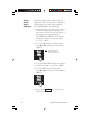
Control programming is easily accomplished with the
front panel pushbuttons. The displays provide a
constant overview of the process. Figure 3.1, on the
next page, summarizes the functions of the
pushbuttons and displays.
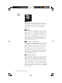
Normal Display Mode
At powerup, and when the controller is not being
programmed, the upper display shows the Process
Value and the lower display shows the setpoint.
The setpoint can be changed in the Normal Display
Mode using the ▲ and ▼ pushbuttons, if the Security
Level allows setpoint changes (see page 26 for Security
Levels).
150
☛
150
RESET
AUX
▲
150
➮
▼
200
RESET
AUX
▲
▼
Use ▲ and ▼ to change
setpoint in Normal
Display Mode.
Chromalox 2104 Technical Manual
21
Figure 3.1
Front Panel
Identification
• Process Variable Display in
Normal Display Mode
• Alphanumeric Menu display
in Setup Mode
LEDs indicate Control
Output #1 or #2 ON
LEDs indicate °F
or °C selected for
Process Variable
LEDs indicate Alarm
or Event Output ON
LED indicates an
Auxiliary function
is active
RESET
Active Setpoint
Display
Pushbutton
• Reset Latching Alarm
• Hold for more than
3 seconds to enter or
exit Setup Mode
• Scrolls through
MENUs in
Setup Mode
AUX
Programmable Pushbutton
• PID1/PID2 Toggle Switch
• Auxiliary Setpoint Enable
• Remote Setpoint Enable
• Output Disable
• Ramp/Soak Operations
• Auto/Manual Selector
• In Normal Display Mode,
pushbuttons adjust Setpoint.
• In Setup Mode, pushbuttons
increase/decrease MENU
values.
• Ramp to Setpoint, press once to
determine target setpoint.
• For Ramp/Soak Operation:
Start
Hold
}
22
Press together
to Stop
Chromalox 2104 Technical Manual
PAGE/MENU
Setup
All control parameters, selections and calibration
procedures for the 2104 are accomplished through
simple MENU selections. These MENU selections are
organized into PAGES. On each PAGE you will find a
specific set of related functions.
This organization allows you to go directly to the
parameter to be adjusted, without stepping through a
long series of unrelated entries. Figure 3.2 illustrates
the 2104 PAGE/MENU setup structure. Only pages
that apply to your unit will be displayed (i.e. if you do
not have Digital Communications option, this page
will not appear).
Figure 3.2
PAGE/MENU Setup Structure
DISP
P A GE
RESET
AUX
▲
▼
▲
RESET
Ramp/
Soak
P A GE
AUX
▼
O UT2
Output #2
AUX
▲
▼
▲
▼
P A GE
AUX
▲
▼
O UT3
RESET
RESET
Custom
Input/Output
Scaling
AUX
▲
Chromalox 2104 Technical Manual
RESET
AUX
▲
▲
▼
Output #1
P A GE
RESET
AUX
▲
▼
O UT4
Output #4
P A GE
▼
RESET
AUX
▲
▼
Digital
Communications
P A GE
▼
AUX
O UT1
Output #3
DIG
Output #5
P A GE
AUX
▲
P A GE
O UT5
RESET
AUX
Input
P A GE
SC
AL
SCA
RESET
P A GE
RESET
IN
PT
NP
Control
P A GE
RSPG
RESET
C TRL
Display
▼
23
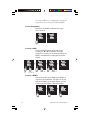
Accessing a MENU is accomplished by entering the
Setup Mode, then selecting a PAGE and MENU.
To enter Setup Mode:
Hold down the RESET pushbutton for longer
than 3 seconds.
250
250
☛
RESET
AUX
▲
L OC
H
OCH
➮
▼
123
RESET
Hold for at least
3 seconds.
AUX
▲
▼
Setup Mode entered.
To select a PAGE:
Press and hold the Reset pushbutton, while
pressing the ▲ or ▼ Pushbutton. The upper
display will increment (or decrement) through the
PAGEs, and PAGE will be displayed in the lower
display.
☛
▼
Press ▲ or ▼
RESET
AUX
▲
➮
▼
RESET
Press ▲ or ▼
Hold
AUX
▲
OU T 1
➮
P A GE
☛
▲
P A GE
☛
☛
Hold
AUX
INPT
☛
➮
250
RESET
C TRL
☛
SP
▼
P A GE
RESET
AUX
▲
▼
Press ▲ or ▼
Hold
To select a MENU:
After reaching the correct PAGE, press RESET to
move through the MENUs. The alpha cue for the
MENU will appear on the upper display, and the
current value will appear in the lower display.
➮
24
AUX
▲
▼
➮
1.0
☛
☛
P A GE
RESET
CY
CL
CYCL
RESET
AUX
▲
▼
OL
OL11
100.0
☛
O UT 1
RESET
AUX
▲
▼
Chromalox 2104 Technical Manual
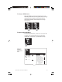
To change a MENU value:
After the MENU is selected and displayed, use the
▲ and ▼ pushbuttons to change the value. For large
adjustments (for example, 100 to 200), hold the
pushbutton pressed and the display will change
more quickly.
➮
☛
1.0
RESET
▲
AUX
C Y CL
▼
1.5
RESET
☛
C Y CL
AUX
▲
▼
To return to Operating Mode:
Press and hold RESET for more than 3 seconds. The
controller will automatically return to operating
mode after 10 minutes of no pushbutton activity.
STB
Y
STBY
☛
101
RESET
▲
AUX
▼
Hold for at least
3 seconds.
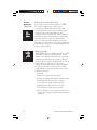
Figure 3.3
Sample of
PAGE/MENU
Table
C TRL
P A GE
RESET
AUX
▲
▼
Control Page
MENU
Description
LO C
H
CH
Security Lock
SP
Available Settings
Security
0 to 9999
A
Setpoint
Instrument sensor span
B
A U SP
Auxiliary SP
Auxiliary setpoint is accessible
only if AUX pushbutton or Event
Input is setup for Auxiliary Setpoint.
Instrument Sensor Span
TUN
E
TUNE
Self Tune
26
29
Self-Tune automatically adjusts PID C
parameters on powerup (PRUP) or
on demand (BEGN).
OFF
PRUP
BEGN
Chromalox 2104 Technical Manual
= Self-tuning disabled
= Power-up tuning
= Begin tuning
25
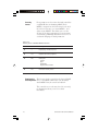
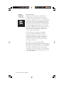
Security
Levels
Every parameter or selection in the 2104 controller’s
setup PAGEs has an identifying MENU. Each
MENU is assigned one of four Security Levels, A-D.
In each level you may view certain MENUs , and
adjust certain MENUs. This allows you to set the
Security level that is appropriate for your operating
environment, prohibiting unauthorized access to or
accidental changing of control parameters.
Figure 3.4
Security Levels and PAGE/MENU Contents
Level
Code
Description
A
---
Display Page and Security Lock
B
123
Setpoint and Auxiliary Setpoint
C
458
Settings for:
Control
Input
Ramp/Soak
Digital Communications
D
736
Calibration Security Codes
Entering the
The Security Code is entered on the Control PAGE
Security Code CTRL, at the MENU LOCK. This code determines
which MENUs may be viewed and adjusted.
The controller is set at Security Level A (view only,
no adjustments) when you receive it from
Chromalox.
26
Chromalox 2104 Technical Manual
To access and enter the Security Code:
1. Press and hold RESET for more than 3 seconds to
enter Setup Mode. Security Lock is the first menu
that will appear.
L OC
H
OCH
☛
123
RESET
AUX
▲
▼
Security Codes
Figure 3.5 lists the Security Codes for each of the
four Security Levels, along with the levels that may
be viewed and adjusted.
Figure 3.5
Security Codes &
View/Adjust
Levels
Security
Level
A
B
C
D
Security
Code
--123
458
736
View
Level
A
A, B
A, B, C
A, B, C, D
Adjust
Level
A
A, B
A, B, C
A, B, C, D
If a number other than one of the three codes listed
above is entered at LOCK on the CTRL PAGE,
adjustment of all parameters is locked out. An
additional security number can be added using the
menu for User Selectable Security Code (CTRL
PAGE, menu CODE).
Chromalox 2104 Technical Manual
27
Control
Operation
C ONT
HEAT
RESET
AUX
▲
▼
C ONT
C OO
L
OOL
RESET
AUX
▲
▼
C ONT
H T CL
RESET
AUX
▲
▼
A
IR
AIR
28
AUX
▲
Control Algorithms
PID is the standard control algorithm of the 2104.
ON/OFF control action is selected by setting the
proportional band (CTRL PAGE, PB1 or PB2) to zero.
Two sets of PID and ON/OFF control parameters are
located in the Control Page for increased flexibility.
Additionally, a Fuzzy Logic algorithm can be used to
help prevent overshoot at power-up or during upsets.
Standard Single Output Control
In standard single output control (CTRL PAGE,
CONT = HEAT or COOL) the Sensor Input is used to
measure the process variable and Output #1 is used
to control the process. PID1 parameters (CTRL
PAGE, DBL, ARL, RATL) are used to determine the
response of the control loop.
Heat/Cool Control
In heat/cool control (CTRL PAGE, CONT = HTCL)
Outputs #1 and #2 are used to control the process.
Output #1 acts as the Heat output and Output #2
acts as the Cool output. PID1 parameters (CTRL
PAGE, PBL, ARL, RATL) are used to determine the
response of the Heat output and PID2 parameters
(CTRL PAGE, PB2, AR2, RAT2) are used for the cool
output.
One way to automatically set the PID2 parameters is
via the cooling medium parameters. These are setup
at menu COOL on the CTRL PAGE.
C OO
L
OOL
RESET
The 2104 Controller is capable of single output and
heat/cool PID control. The selection for single or
heat/cool control is made in the Controller Type
menu (CTRL PAGE, CONT) with PID settings also in
the Control Page. Additionally, the 2104 features
ramp to setpoint and ramp/soak capabilities.
▼
Cooling Medium parameters automatically establish
the optimum PID2 cooling parameters, based on the
cooling medium used/selected. If air, oil or water
cooling medium is selected, and PID1 parameters
change (during self-tune OR Manually), PID2
parameters will also be adjusted. If “PID2” is selected
(PAGE CTRL, COOL = PID2, no cooling medium
specified), the PID2 parameters will change only if
changed in Menus PB2, AR2 and RAT2.
Chromalox 2104 Technical Manual
Control
Operation
(continued)
TUNE
PR
UP
PRU
RESET
AUX
▲
▼
TUNE
B EGN
RESET
AUX
▲
▼
Self-Tuning
The 2104 tuning algorithm establishes PID
constants (PBL, ARL, RATL) that will bring the
process to setpoint as quickly as possible with little
overshoot. Tuning can be performed at powerup
(CTRL PAGE, TUNE = PRUP) or can be initiated
immediately (CTRL PAGE, TUNE = BEGN). When
tuning, the 2104 will flash “TUNE” in the lower
display.
If the process variable is not at least 50°F (28°C)
away from setpoint, the 2104 will turn off the
control output until the process temperature is 50°F
from setpoint. If the 50°F temperature difference is
not reached within 30 minutes, “TERR” will be
displayed, indicating that tuning was not successful
(tuning error). Press RESET to clear “TERR”. After
successfully tuning, tuning is turned OFF in the
tuning menu (TUNE).
Heat/Cool Self-Tuning
For heat/cool control applications, when the
cooling medium is specified (PAGE CTRL, COOL =
AIR, H2O, OIL), both heat (PID1) and cool (PID2)
parameters are computed during a heat tune
(tuning is invoked while the process temperature is
at least 50°F below setpoint). If no cooling medium
is specified (PAGE CTRL, COOL = PID2) the PID2
parameters (PB2, AR2, RAT2) will not change
during a self-tune.
A cool tune (tuning is invoked while the process
temperature is at least 50°F above setpoint) will
compute PID parameters for cooling only. One way
to initiate a cool tune is to first heat tune, then
lower the setpoint by 50°F (28°C) and initiate selftuning for cooling (CTRL PAGE, TUNE = BEGN). A
cool tune will change PID2 settings if Heat/Cool
control is selected for the control type (CTRL PAGE,
CONT HTCL).
Chromalox 2104 Technical Manual
29
Control
Operation
(continued)
FL
ON
RESET
AUX
▲
▼
RR
AT
RRA
20
RESET
AUX
▲
▼
Fuzzy Logic Overshoot Protection
Fuzzy Logic Overshoot Protection (CTRL PAGE,
FL) works to minimize the overshoot that
accompanies standard PID control. The 2104
actively learns the characteristics of the load and
adjusts the PID control algorithm to reduce
overshoot. Overshoot Protection, when combined
with PID constants established by the 2104 tuning
algorithm, produces a response that brings the
process to setpoint with a minimum of overshoot.
Fuzzy Logic overshoot protection is not possible with
ON/OFF type control. It is recommended that Fuzzy
Logic is always enabled.
Ramp to Setpoint
(CTRL PAGE, RRAT = 1 to 9999 degrees/hour or OFF)
The Ramp to Setpoint feature allows the control
setpoint to be ramped to the final value at powerup
or during operation when the setpoint is adjusted.
At powerup, the setpoint is ramped from the current
measured process temperature to the control
setpoint. During operation, the setpoint is ramped
from the current value to the new value. When
enabled, Ramp to Setpoint will begin in any of the
following situations:
• Powerup
• Change of setpoint from front panel
• Change of setpoint from digital communications
• Digital Input or Aux Key used to change
between the local and auxiliary setpoints
• Digital Input or Aux Key used to change
between the local and remote setpoints
• Remote Setpoint is active and the remote device
changes the setpoint faster than the programmed
ramp rate
30
Chromalox 2104 Technical Manual
Control
Operation
(continued)
ENTI
A UTO
RESET
AUX
▲
▼
Manual Operation
Manual operation allows the controller output
command to be controlled from the front panel
Keyboard. On initial powerup, the controller enters
Automatic control mode (closed loop). When Manual
Mode is entered, the output command appears in the
lower display. The output command can be adjusted
using the up and down arrow keys. The manual mode
can be entered by using the Aux Key or the Digital
Input (CTRL PAGE, ENTI or AUTO). Manual Operation
is not possible when ramp/soak is enabled. In the
heat/cool control mode, only the currently active
control output can be adjusted.
The transfer between Automatic and Manual
operation is bumpless and balanceless. When
switching from automatic to manual control, the
controller assumes the last output command from
automatic mode. When returning to automatic
control, the output is forced to be the last manual
mode output command.
If automatic reset is enabled (CTRL PAGE,
AR = non-zero value) the integral value slowly changes
the output value until it reaches the correct automatic
(PID) output value. If automatic reset is not enabled,
the output is ramped from the last manual output
command to the current automatic output command
at a rate determined by the disintergration time menu
(CTRL PAGE, AUTO).
Chromalox 2104 Technical Manual
31
32
Chromalox 2104 Technical Manual
Section 4
Controller Setup PAGEs
This section contains detailed information for the
following controller setup pages:
DISP: Display
CTRL: Control
INPT: Input
SCAL: Custom Scaling
OUT1: Output #1
OUT2: Output #2
Section
Contents
Setup PAGEs specific to certain functions are located
in the section of this manual that addresses that
function specifically.
Section
Page
Topic
Setup PAGE
5
41
Ramp/Soak
RSPG
6
47
Alarms and Events
OUT3, OUT4, OUT5
8
67
Remote Setpoint Input and
CTRL, INPT, SCAL
Analog Output Option
9
71
More
Info.
Digital Communications
DIG
Throughout the following Setup PAGEs you will find
these symbols 40 . This indicates a section of this
User’s Manual where more specific information on a
parameter/application/feature can be found.
Chromalox 2104 Technical Manual
33
DISP
P A GE
RESET
AUX
▲
▼
The Display Page is for status only.
None of the settings can be changed.
Display Page
MENU
Description
Displays
PROC
Process Variable
Sensor Span
A SP
Active Setpoint
Sensor Span
O UT1
Output #1 Command
0.0 TO 100.0
100.0%
O UT2
Output #2 Command
0.0 TO 100.0
100.0%
RSP
Remote Setpoint Input
Sensor Span
RS
Ramp/Soak Status
O FF
RUN
H OLD
STB
Y
STBY
GS
INT
Ramp/Soak Interval Number
0 - 16
L EFT
Ramp/Soak Time Left in Interval
0.0 TO 999.9 hr/min/sec
=
=
=
=
=
Security
A
Program not running
Program running
Program in hold
Program in standby
Guaranteed soak
L OOP
Ramp/Soak Loops Remaining
0 - 9999
A LR
Alarm Output Status
N ONE
A3
A4
A4
3
43
A5
A5
3
53
A5
4
54
A54
3
A543
=
=
=
=
=
=
=
=
No alarms
Alarm Output #3
Alarm Output #4
Alarm Outputs #4 and #3
Alarm Output #5
Alarm Outputs #5 and #3
Alarm Outputs #5 and #4
Alarms 5, 4 and 3
E NT
Event Output Status
N ONE
E3
E4
E4
3
43
E5
E5
3
53
E5
4
54
E54
3
E543
=
=
=
=
=
=
=
=
All off
Event Output #3
Event Output #4
Event Outputs #4 and #3
Event Output #5
Event Outputs #5 and #3
Event Outputs #5 and #4
Events 5, 4 and 3
34
Chromalox 2104 Technical Manual
C TRL
P A GE
RESET
AUX
▲
▼
Control Page
MENU
Description
Available Settings
LO C
H
CH
Security Lock
0 to 9999
A
SP
Setpoint
Instrument sensor span
B
A U SP
Auxiliary SP
Auxiliary setpoint is accessible
only if AUX pushbutton or Event
Input is set up for Auxiliary Setpoint.
Instrument Sensor Span
TUN
E
TUNE
Self-Tune
26
29
Security
Self-Tune automatically adjusts PID C
parameters on powerup (PRUP) or
on demand (BEGN).
OFF
PRUP
BEGN
= Self-tuning disabled
= Power-up tuning
= Begin tuning
PB1 - DB1
DB1) applies to Output #1 in heat/cool mode. For single output
PID1 (PB1
control, PID1 (PB1-DB1) can be switched with PID2 (PB2 - DB2) settings via AUX
pushbutton or Digital Input.
PB1
Proportional Band 1
0°F to sensor range
C
0°F displays as OnOF to
indicate ON/OFF control
AR1
Automatic Reset 1
0.00 to 99.99 repeats/minute
RAT1
Rate 1
0 to 500 seconds
DB1
Dead Band 1
DB1 is not used unless PB1 is set to zero.
1 to 100°F
0.01 to 6.25% span for analog inputs
PB2 - DB2
PID2 (PB2
DB2) applies to Output #2 in heat/cool mode. For single output
control, can be used for Output #1, if switched via AUX pushbutton or Digital
Input.
PB2
Proportional Band 2
0°F to sensor range
0°F displays as OnOF to
indicate ON/OFF control
AR2
Automatic Reset 2
RAT2
Rate 2
0 to 500 seconds
DB
2
B2
Dead Band 2
DB2 is not used unless PB2 is set to zero.
1 to 100°F
0.01 to 6.25% span for analog inputs
Chromalox 2104 Technical Manual
0.00 to 99.99 repeats/minute
35
C TRL
P A GE
RESET
AUX
▲
▼
Control Page (continued)
MENU
Description
Available Settings
OFS
T
OFST
Manual Reset
FL
Fuzzy Logic
O RNG
Open Sensor Output Command
L OOP
Control Loop Protection Timer 55 OFF, 0.1 to 999.9 minutes
A UTO
Auto/Manual Disintegration Timer
0 to 100 seconds
RR
AT
RA
Ramp Rate
OFF
1 to 9999 degrees/hour
C ONT
Controller Type
-99.9 to 99.9
29
28
OFF
ON
=
=
Controller type can be used as
heat/cool (HTCL) only if controller is
equipped with Output#1 (Heat) and
Output #2 (Cool).
HEAT = Reverse Acting Single
Output Controller
=
=
HTCL
Cooling Medium
R SP
Remote Setpoint Enable
E NTI
Event/Digital Input
Function
36
28
C
Disabled
Enabled
In the event of an open sensor,
control output will automatically
adjust to % output preset. For
Heat Only or Cool Only control,
adjustable 0.0 to 100.0%.
For Heat/Cool Control, adjustable:
-100.0 to 100.0%:
-100.0 to -0.1 for cooling
0.1 to 100.0 for heating
COOL
CO O
L
OL
Security
Direct Acting Single
Output Controller
Heat/Cool Controller
PID2
=
AIR
OIL
H2O
=
=
=
Uses PID2 settings for
cooling
Air Cooling
Oil Cooling
Water Cooling
=
=
=
=
=
=
=
=
Disabled
PID2 enable
Auxiliary SP enable
Remote SP enable
Output disable
Ramp/Soak
Auto/Manual
Alarm Reset
OFF
ON
59
NONE
PID2
AUSP
RSP
OUTD
RS
AUTO
ALR
Chromalox 2104 Technical Manual
C TRL
P A GE
RESET
AUX
▲
▼
Control Page (continued)
MENU
Description
Available Settings
AU
Auxiliary Pushbutton
Function
60
A OUT
Analog Output Assignment
70
NONE
PROC
ASP
OUT1
OUT2
RS E
N
EN
Ramp/Soak
41
Ramp/Soak “On” enables the
Ramp/Soak Setup Page (R5PG)
OFF
ON
CO D
E
DE
User Selected
Security Code
26
Allows you to establish your own
user-defined security code.
0-122
= Level A
123-457 = Level B
458-735 = Level C
736-999 = Level D
Chromalox 2104 Technical Manual
NONE
PID2
AUSP
RSP
OUTD
AUTO
=
=
=
=
=
=
Disabled
PID2 enable
Auxiliary SP enable
Remote SP enable
Output disable
Auto/Manual
=
=
=
=
=
Disabled
Process Variable
Active Setpoint
Control Output 1
Control Output 2
Security
C
D
37
I NPT
P A GE
RESET
AUX
▲
▼
Input Page
MENU
Description
38
Sensor Type
Available Settings
Security
4
Sensor Type selected here must
C
agree with dip switch settings.
J
= J Thermocouple
K
= K Thermocouple
T
= T Thermocouple
E
= E Thermocouple
R
= R Thermocouple
S
= S Thermocouple
B
= B Thermocouple
RTD = 100Ω Pt RTD (α = .00385)
4-20 = 4 to 20mA
0-5 = 0 to 5 Vdc
1-5 = 1 to 5 Vdc
RTDT = 100 Ω Pt RTD
(0.1° resolution)
UNIT
Display Units
NONE = no units
°F
= Degrees Fahrenheit
°C
= Degrees Celsius
C O FF
Display/Calibration 82
Display/Calibration Offset offsets
Offset
temperature process reading.
-100°F to 100°F
Setpoint Limits prevent setpoints from being adjusted above or below these
pre-established limits.
SPLL
Setpoint Low Limit
Instrument Sensor Span
SPUL
Setpoint Upper Limit
Instrument Sensor Span
CALS
Sensor Calibration
INLO
D
INHI
DONE
CAL
R
CALR
Remote Setpoint Calibration
INLO
INHI
DONE
AO 0
Analog Output Zero Calibration
0 to 4095
AO 5
Analog Output Span Calibration
0 to 4095
REC
C
ECC
Factory Calibration Recovery
RDY = Ready
--- = Wait
DONE = Finished
FILT
Digital Filtering menu (FILT
FILT) can be used to stabilize a fluctuating 0.1° resolution
process variable display. To stabilize the display, increase the menu value
(adjustable from 1 to 60 seconds).
F IIL
LT
Digital Filter
0 to 60 seconds
HPRC
High (max.) Process Input
Instrument Sensor Span
L PRC
Low (min.) Process Input
Instrument Sensor Span
H IIA
A
High (max.) Ambient Temp.
Instrument Sensor Span
LOA
Low (min.) Ambient Temp.
Instrument Sensor Span
SE
NS
EN
Chromalox 2104 Technical Manual
SC
AL
SCA
P A GE
RESET
▲
AUX
This PAGE appears only when Analog Input
is selected, Remote SP is enabled, or Analog
Output is enabled on CTRL PAGE.
▼
Custom Scaling Page
MENU
Description
Available Settings
DP
Analog Input Decimal Pts.
9
AI N
L
NL
Analog Input Low
9
-500 to 5000
AI N
H
NH
Analog Input High
9
-500 to 5000
AO T
L
TL
Analog Output Low
70
-500 to 5000
AO T
H
TH
Analog Output High
70
-500 to 5000
R SPL
Remote SP Input Low
67
-500 to 5000
R SPH
Remote SP Input High
67
-500 to 5000
0
1
2
3
=
=
=
=
Security
none
123.4
12.34
1.234
C
O UT1
P A GE
RESET
AUX
▲
▼
Output #1 Page
MENU
Description
Available Settings
Security
C Y C1
Output #1 Cycle Time
0.0 to 60.0 seconds
0.0 = Voltage/Current algorithm
OL
L11
Output #1 Limit
0.0 to 100.0%
H OFF
Heat Offset
0°F to PB1 setting
C
O UT2
P A GE
RESET
AUX
▲
▼
This PAGE is visible only if setup for
heat/cool control on CtrL PAGE.
Output #2 Page
MENU
Description
Available Settings
C Y C2
Output #2 Cycle Time
0.0 to 60.0 seconds
0.0 = Voltage/Current algorithm
OL
2
L2
Output #2 Limit
0.0 to 100.0%
C OFF
Heat Offset
0°F to Pb2 setting
Chromalox 2104 Technical Manual
Security
C
39
40
Chromalox 2104 Technical Manual
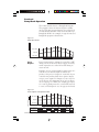
Section 5
Ramp/Soak Operation
The 2104 controller features a Ramp/Soak Program.
The program consists of 16 intervals plus a standby
interval. The time span and setpoint for each interval
are individually adjustable. These intervals make up a
Ramp/Soak Profile. An example of a typical 8-interval
Ramp/Soak program is shown below.
Figure 5.1
Ramp/Soak Profile
Temperature
+ Dev. Alarm
Setpoint
Standby
Low Alarm
Time
Event
Outputs
Event Outputs may be configured to turn ON or OFF
during each of the intervals. Event outputs are merely
timed outputs that are either ON or OFF during an
entire interval.
Examples of event outputs might be annunciation of a
soak interval, an indicator light or addition of a
product to the process. Outputs #3, #4 and #5 (if your
controller was purchased with these options) may be
setup as event outputs. For Outputs #3, #4 or #5 to be
used as Events, the output must be set up as an Event
on its setup page (i.e. OUT3). For example, for Output
#3 to turn on during interval 2, set menu 2E (interval
2 event) to E3 (Output #3 on). See page 43 for details.
Figure 5.2
Event Outputs in Ramp/Soak Profile
Temperature
+ Dev. Alarm
Setpoint
Low Alarm
Time
Event 1 (Out #3)
ON
Event 2 (Out #4)
Chromalox 2104 Technical Manual
ON
ON
ON
ON
ON
ON
ON
ON
41
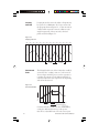
Looping means that intervals within a Program may
be repeated 1 to 9999 times. If a loop is inserted in
the program shown in Figure 5.1, so that intervals 4,
5 and 6 will be repeated 2 times in addition to the
single Program run of these intervals, the final
profile would look Figure 5.3.
Looping
Intervals
Figure 5.3
Looping Intervals
INT 1
INT 2
INT 3
INT 4
INT 5
INT 6
INT 4
INT 5
INT 6
INT 4
1st Loop
Guaranteed
Soak
INT 5
INT 6
INT 7
INT 8
2nd Loop
This Ramp/Soak feature of the 2104, when enabled,
assures that the “soaking” time in a “soak” interval
does not begin until the process reaches setpoint or
is within the guaranteed soak differential band. A
soak interval has the same setpoint at the beginning
and end of the interval.
Figure 5.4
Guaranteed Soak
Temp
1 Hour
Time
Programmed Setpoints
Actual Process Temp
Guaranteed Soak is enabled on the RSPG PAGE by
setting the differential band to a value greater
than 0. It is adjustable from 1°F to the sensor span.
42
Chromalox 2104 Technical Manual
RSPG
P A GE
RESET
AUX
▲
This setup PAGE appears only if Ramp/Soak
control is turned on. The Ramp/Soak Enable
parameter is the next to the last menu on
CTRL PAGE, Menu CONT.
▼
Ramp/Soak Page
MENU
Description
Available Settings
UNIT
Time Units
SEc
MIN
HR
STB
Y
STBY
Standby Setpoint
Instrument Sensor Span
INT1
Interval 1 Time
see Time Units Menu (above)
SP1
Setpoint 1
•
• Intervals 2-15
• Time and Setpoint
Instrument Sensor Span
IN16
Interval 16 Time
see Time Units Menu (above)
SP16
Setpoint 16
Instrument Sensor Span
C ONT
Continuous Program
OFF
ON
F RO
Loop from the end of interval 42
1 to 16
TO
To the beginning of interval
1 to 16
NO
Number of times
0 to 9999
SBET
Standby Events
41
OFF
E3
E4
E43
E5
E53
E54
E543
=
=
=
=
=
=
=
=
All off
Event Output 3 On
Event Output 4 On
Event Outputs 4 & 3 On
Event Output 5 On
Event Outputs 5 & 3 On
Event Outputs 5 & 4 On
Event Outputs 5, 4, 3 On
ILE
Interval 1 Events
41
OFF
E3
E4
E43
E5
E53
E54
E543
=
=
=
=
=
=
=
=
All off
Event Output 3 On
Event Output 4 On
Event Outputs 4 & 3 On
Event Output 5 On
Event Outputs 5 & 3 On
Event Outputs 5 & 4 On
Event Outputs 5, 4, 3 On
IL6E
Interval 16 Event
41
same as above
G SDB
Guaranteed Soak differential
Chromalox 2104 Technical Manual
42
=
=
=
Security
seconds (1 to 9999)
minutes (0.1 to 999.9)
hours (0.01 to 99.99)
C
OFF, 1°F to sensor range
43
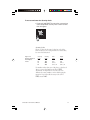
Control
Operation
In order to use the Ramp/Soak program, it must be
enabled on the CTRL Page, RSEN = ON. Control of
ramp/soak operation (Start, Stop and Hold) can be
accomplished via the front panel. In the Setup
mode, first return to the Normal Display Mode by
holding the reset button for 3 seconds. Pressing the
up arrow key Starts the program, pressing the down
arrow key Holds the program, and pressing both
together Stops the program.
To Start Ramp/Soak Program:
80
R/S Indicator
ON
☛
70 .
RESET
▲ Starts the Ramp/
Soak program or if the
program is on Hold,
continues the program
AUX
▲
▼
Press ▲
To Hold Ramp/Soak Program:
100
R/S Indicator
Flashes
AUX
☛
100 .
RESET
▲
▼
▼ (Hold) Stops the
program in progress
and “holds” the
program until the
▲ (Start) button is
pressed.
Press ▼
To Stop Ramp/Soak Program:
140
R/S Indicator
OFF
140 .
AUX
☛
☛
RESET
▲
▼ and ▲ together
(Stop Pushbutton)
return the Ramp/Soak
program to the
Standby setpoint.
▼
Press ▲ and ▼ together
44
Chromalox 2104 Technical Manual
Ramp/Soak (continued)
Alternately, the Digital Input or Chromasoft™ can be
used to control program operation. The ramp/soak
indicator LED (right-most decimal point in the lower
display) is ON when a program is running, OFF in
standby, and flashes in hold mode.
449
▼
RESET
AUX
▲
Status: Run
Chromalox 2104 Technical Manual
L EFT
➮
RUN
▼
☛
▲
☛
AUX
STAT
➮
450
RESET
Note: If the Aux key function is set to none
CTRL P
AGE
(C
PA
GE, AU = NONE
NONE), the current ramp/soak
status will be displayed when the Aux key is pressed.
➮
1
RESET
AUX
▲
L OOP
▼
# Intervals Left
0
☛
☛
☛
Control
Operation
(continued)
RESET
AUX
▲
▼
# Loops Left
45
46
Chromalox 2104 Technical Manual
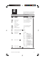
Section 6
Alarms
The 2104 controller can provide up to three alarm
outputs using Output #3, #4 and #5. These optional
outputs are indicated by the following controller
model numbers:
Optional Outputs
Model Number
Outputs #3 and #4
2104 - **1**
Output #5
2104 - ***1*
2104 - ***2*
2104 - ***4*
2104 - ***5*
Each alarm is individually setup with a high and low
setpoint on its own Page:
• OUT3 PAGE
• OUT4 PAGE
• OUT5 PAGE
Outputs #3, #4 and #5 can be individually setup as
Alarms or Events, and can be individually disabled.
To function as an alarm, the output type must be
specified as an alarm output, ALR, in the first menu,
output type (TYP3, TYP4, TYP5). If the function is an
Event, the output type must be specified as ENT. The
Events then are enabled in the Ramp/Soak (RSPG)
page, menus SBET (Standby Event) through I16E.
O UT3
➮
☛
P A GE
RESET
AUX
Chromalox 2104 Technical Manual
▲
▼
TYP3
AL
R
ALR
RESET
AUX
▲
▼
47
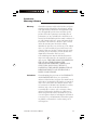
Alarm Types
Each of the alarms can be set up for the following
alarm types:
HI
High Alarm—Absolute Temperature Alarm
LO
Low Alarm—Absolute Temperature Alarm
HILO
High/Low Alarm—Absolute Temperature Alarm
PDE
+Deviation Alarm—Setpoint Tracking Alarm
-DE
-Deviation Alarm—Setpoint Tracking Alarm
DE
±Deviation Alarm—Setpoint Tracking Alarm
L OO
P Control Loop Protection Alarm—System Alarm
OOP
(see page 53 for detailed information)
The Absolute Temperature Alarms are set to a
specific value; i.e. if the High Alarm is set for 100°F,
the alarm will turn on at 100°F. The Deviation
Alarms, or Setpoint Tracking Alarms, track the
process setpoint. If the Alarm = 5°F and the setpoint
is 70°F, the Alarm will energize at 75°F.
Alarm
Inhibit
When enabled, the Alarm Inhibit feature prevents
false alarms during initial powerup. For example, the
low alarm will not be set until after the process
temperature has initially reached setpoint. Alarm
Inhibit is adjustable for each alarm output.
INH3
O
N
ON
RESET
Alarm
Wiring
48
AUX
▲
▼
Wiring instructions for Outputs #3, #4 and #5 are
given on pages 19-20.
Chromalox 2104 Technical Manual
Alarm
Relay
Action
Output Relays #3, #4 and #5 can be set to be normally
energized or de-energized, latching or non-latching. A
normally de-energized relay is in its non-energized
state when not in alarm. For example, Outputs #3 and
#4 are normally-open contacts. When setup as
normally de-energized, the relays will be open when
not in alarm, and closed when in alarm.
A non-latching relay will not stay in alarm if the alarm
condition goes away. A latching relay will not go out
of alarm until the alarm condition no longer exists and
RESET is pressed.
Alarm
Operation
Latching alarms can be reset by pressing the RESET
pushbutton on the controller front panel. The alarm
cannot be reset until the process is out of the alarm
condition. The Digital Input can be setup to function
as a remote alarm reset button (see pages 59-63).
ENTI
☛
RSP
RESET
AUX
Chromalox 2104 Technical Manual
▲
▼
49
O UT3
P A GE
RESET
AUX
▲
This setup PAGE appears only if the
controller is equipped with Outputs #3
and #4.
▼
Output #3 Page
MENU
Description
Available Settings
T Y P3
Output #3 Type
47
A LR3
Alarm #3 Type
48
RLY3
Alarm #3 Relay Action
49
Security
OFF
= Disabled
C
ALR
= Alarm Output
ENT
= Event Output
(Setup Event Output parameters
on Ramp/Soak Page)
NONE = Disabled (off)
Hi
= High Alarm
Lo
= Low Alarm
HiLo = High-Low Alarm
PDE
= Plus Deviation Alarm
-DE
= Minus Deviation Alarm
DE
= Plus/Minus Deviation Alarm
LooP = Control Loop Protection Alarm
NDE
=
NE
=
NDEL
=
NEL
=
Normally de-energized
non-latching
Normally energized
non-latching
Normally de-energized
latching
Normally energized
latching
Low Setpoint is used for low and -deviation setpoints
AL
O3
LO3
Alarm #3 Low Setpoint
Instrument Sensor Span
High Setpoint is used for high and +deviation setpoints
AH
I3
HI3
Alarm #3 High Setpoint
Instrument Sensor Span
DB3
Output #3 Dead Band
(Alarm Hysteresis)
0 to 100°F
INH3
Alarm #3 Inhibit
50
48
OFF
ON
Chromalox 2104 Technical Manual
O UT4
P A GE
RESET
AUX
▲
This setup PAGE appears only if the
controller is equipped with Outputs #3
and #4.
▼
Output #4 Page
MENU
Description
Available Settings
T Y P4
Output #4 Type
47
A LR4
Alarm #4 Type
48
RLY4
Alarm #4 Relay Action
49
Security
OFF
= Disabled
C
ALR
= Alarm Output
ENT
= Event Output
(Setup Event Output parameters
on Ramp/Soak Page)
NONE = Disabled (off)
HI
= High Alarm
LO
= Low Alarm
HILO = High-Low Alarm
PDE
= Plus Deviation Alarm
-DE
= Minus Deviation Alarm
DE
= Plus/Minus Deviation Alarm
LOOP = Control Loop Protection Alarm
NDE
=
NE
=
NDEL
=
NEL
=
Normally de-energized
non-latching
Normally energized
non-latching
Normally de-energized
latching
Normally energized
latching
Low Setpoint is used for low and -deviation setpoints
AL
O4
LO4
Alarm #4 Low Setpoint
Instrument Sensor Span
High Setpoint is used for high and +deviation setpoints
AH
I4
HI4
Alarm #4 High Setpoint
Instrument Sensor Span
DB4
Output #4 Dead Band
(Alarm Hysteresis)
0 to 100°F
INH4
Alarm #4 Inhibit
Chromalox 2104 Technical Manual
48
OFF
ON
51
O UT5
P A GE
RESET
AUX
▲
▼
This setup PAGE appears only if the
controller is equipped with Output #5.
Output #5 Page
MENU
Description
Available Settings
T Y P5
Output #5 Type
47
A LR5
Alarm #5 Type
48
RLY5
Alarm #5 Relay Action
Security
OFF
= Disabled
C
ALR
= Alarm Output
ENT
= Event Output
(Setup Event Output parameters
on Ramp/Soak Page)
NONE = Disabled (off)
HI
= High Alarm
LO
= Low Alarm
HILO = High-Low Alarm
PDE
= Plus Deviation Alarm
-DE
= Minus Deviation Alarm
DE
= Plus/Minus Deviation Alarm
LOOP = Control Loop Protection Alarm
49
NDE
=
NE
=
NDEL
=
NEL
=
Normally de-energized
non-latching
Normally energized
non-latching
Normally de-energized
latching
Normally energized
latching
Low Setpoint is used for low and -deviation setpoints
AL
O5
LO5
Alarm #5 Low Setpoint
Instrument Sensor Span
High Setpoint is used for high and +deviation setpoints
AH
I5
HI5
Alarm #5 High Setpoint
Instrument Sensor Span
DB5
Output #5 Dead Band
(Alarm Hysteresis)
0 to 100°F
INH5
Alarm #5 Inhibit
52
48
OFF
ON
Chromalox 2104 Technical Manual
Control Loop Protection Alarm (CLP)
Control Loop Protection (CLP) monitors the
controller’s process variable input and load output to
detect and respond to conditions indicating a failure in
the control loop (Sensor, Controller Output, Load or
Process flow). CLP is selected by setting the LOOP Timer
on the CTRL PAGE menu to a value from 0.1 to 999.0
minutes (0.0 disables CLP).
➮
☛
P A GE
RESET
AUX
▲
L OOP
▼
Loop Timer
120.0
RESET
Time (in minutes)
☛
C TRL
AUX
▲
▼
The timer setting should be chosen according to the
response time of the system. The minimum time seting
should be 0.25% of span divided by the normal load
response rate to full ON or full OFF condition
(whichever is slower).
Minimum Timer Setting =
Span x .0025
Slowest Response Rate (Heat or Cool)
Response Rate = Process Response (in degrees/minute) when
100% ON or 100% OFF
Example: For a controller with type J T/C (span -100°F
to 1400°F), 0.25% of span is 3.75°F. If the heating
response is 2°F/min., and the cooling response is 1°F/
min., the minimum Loop Timer setting would be 3.8
minutes. To prevent false alarms, it is recommended that
you start by doubling the setting to 7.6 minutes.
The CLP Alarm sequence begins when the control
output reaches 0.0% or 100.0% (process variable outside
of the proportional band). The controller then measures
the time for the process variable to respond (increase or
decrease the process variable) and compares the
measured time to the Loop Timer value.
Chromalox 2104 Technical Manual
53
Control Loop Protection Alarm (continued)
If the control loop does not respond with a change
in the process variable of 0.25% of span (3.75°F for
a J thermocouple) within the programmed loop
time, a Loop Error will result and the control output
will turn off. The error will be indicated by the
lower display flashing LOOP and Loop Alarm Output
(Output #3, #4, or #5 as selected on the menu) will
be activated. The Loop Alarm is cleared by pressing
RESET.
L OOP
Press RESET
to clear Loop Alarm
RESET
☛
54
AUX
☛
O FF
▲
▼
Warning
The CLP is not a substitute for safety shutdown
devices such as flow switches or overtemperature
monitors. The CLP Alarm responds to specific
conditions that may provide early warning of system
loop failures or aid in troubleshooting failures.
Chromalox 2104 Technical Manual
CLP Loop Alarm Conditions
The following table details conditions that activate a loop alarm, and gives
the controller response to the condition.
Figure 6.1 CLP Loop Alarm Conditions
Probable Cause
Control Output Response
Loss of process flow
Turns control output off
Display
8888
L OOP
Flashing
In a control application where the process is being heated at one point and measured at a
point downstream, CLP Alarm could be used to detect a flow failure. If the process flow is
interrupted and heat is no longer transferred to the sensor, the controller output will
increase to 100%, the Loop alarm will start timing the load response and when the preset
Loop Timer value is reached, the Loop Alarm will be activated and the control output will
be turned off. The failure will be indicated by the lower display flashing LOOP. Loop Alarm
Output (Output #3, #4 or #5) will be activated if selected.
Probable Cause
Control Output Response
Load Power is interrupted
(blown fuse or tripped circuit
breaker)
Turns control output off
Display
8888
L OOP
Flashing
If load power is interrupted by the circuit protection devices (user supplied fuse or circuit
breaker), the Loop Alarm will be activated when the process variable goes outside of the
proportional band for a time greater than the preset Loop Timer value. The control output
will be turned off and the failure will be indicated by the lower display flashing LOOP. Loop
Alarm Output (Output #3, #4, or #5) will be activated If selected.
Probable Cause
Control Output Response
Load fails (open circuit)
Turns control output off
Display
8888
L OOP
Flashing
If the load fails open, the Loop Alarm will be activated when the process variable goes
outside of the proportional band for a time greater than the preset Loop Timer value. The
control output will be turned off and the failure will be indicated by the lower display
flashing LOOP. Loop Alarm Output (Output #3, #4, or #5) will be activated if selected.
Probable Cause
Control Output Response
Load fails (short circuit)
Turns control output Off
Display
8888
L OOP
Flashing
If the load fails shorted, power to the load will be interrupted by the circuit protection
devices (user supplied fuse or circuit breaker). The Loop Alarm will be activated when the
process variable goes outside of the proportional band for a time greater than the preset
Loop Timer value. The control output will be turned off and the failure will be indicated by
the lower display flashing LOOP. Loop Alarm Output (Output #3, #4, or #5) will be
activated if selected.
(continue on the next page)
Chromalox 2104 Technical Manual
55
Figure 6.1 CLP Loop Alarm Conditions (continued)
Probable Cause
Control Output Response
Controller or remote power
Turns control output off
control output fails (open circuit)
Display
8888
OP
LO O
P
Flashing
If the controller output or the remote power control device (SCR or contactor) fails open,
the Loop Alarm will be activated when the process variable goes outside of the
proportional band for a time greater than the preset Loop Timer value. The failure will be
indicated by the lower display flashing LOOP. Loop Alarm Output (Output #3, #4, or #5)
will be activated if selected.
Probable Cause
Control Output Response
Controller or remote power
control output fails (short circuit)
None
(load must be interconnected with alarm)
Display
8888
L OOP
Flashing
If the controller output or the remote power control device (SCR or contactor) fails
shorted, the Loop Alarm will be activated when the process variable goes outside of the
proportional band for a time greater than the preset Loop Timer value. The failure will be
indicated by the lower display flashing LOOP. Loop Alarm Output (Output #3, #4, or #5)
will be activated. To protect the loop under this condition, the Loop Alarm Output (Output
#3, #4 of #5) should be interconnected to remove power from the load.
Probable Cause
Control Output Response
Sensor wiring reversed
(thermocouple only)
Turns control output off
Display
8888
L OOP
Flashing
If the sensor wiring is reversed, the Loop Alarm will be activated when the process variable
goes outside of the proportional band for a time greater than the preset Loop Timer value.
The control output will be turned off and the failure will be indicated by the lower display
flashing LOOP. Loop Alarm Output (Output #3, #4, or #5) will be activated if selected.
Probable Cause
Control Output Response
Sensor loses contact
with process
Turns control output off
Display
8888
L OOP
Flashing
If the sensor loses contact with the process (sensor becomes dislodged or pulled loose),
the Loop Alarm will be activated when the process variable goes outside of the
proportional band for a time greater than the preset Loop Timer value. The failure will be
indicated by the lower display flashing LOOP. Loop Alarm Output (Output #3, #4, or #5)
will be activated if selected.
Probable Cause
Control Output Response
Display
Sensor fails (open circuit)
Defaults to preset (0-100%)
OPEN
SENS
Flashing
If the sensing device fails open, the controller defaults to the preset output condition
(0-100% ORNG setting selected on the CTRL PAGE menu) and uses both displays to
indicate OPEN SENS. The Loop alarm is not activated for this condition. Alarms selected
as Low, High-Low, + Deviation or +/- Deviation will actuate if selected.
(continued on the next page)
56
Chromalox 2104 Technical Manual
Figure 6.1 CLP Loop Alarm Conditions (continued)
Probable Cause
Control Output Response
Display
Sensor fails
(short circuit, RTD only)
Defaults to preset (0-100%)
OPEN
SENS
Flashing
If the RTD sensing device fails shorted, the controller defaults to the preset output
condition (0-100% ORNG setting selected on the CTRL PAGE menu) and uses both displays
to indicate OPEN SENS. The Loop alarm is not activated for this condition. Alarms selected
as Low, High-Low, - Deviation or +/- Deviation will actuate if selected.
Probable Cause
Control Output Response
Display
Controller Self Diagnostic
(signal conversion)
Defaults to preset (0-100%)
8888
R4
ER R
4
Flashing
If a failure occurs in the signal conversion circuit of the controller, the controller defaults
to the preset output condition (0-100% ORNG setting selected on the CTRL PAGE menu)
and displays ERR4 on the lower display. Loop Alarm Output (Output #3, #4, or #5) will be
activated if selected.
Probable Cause
Control Output Response
Controller Self Diagnostic
Turns control output off
Display
8888
R3
ER R
3
Flashing
If a failure occurs in the control circuitry of the controller, the control output will be turned
off and ERR3 will be displayed on the lower display. Loop Alarm Output (Output #3, #4, or
#5) will be activated if selected.
Chromalox 2104 Technical Manual
57
58
Chromalox 2104 Technical Manual
Section 7
Digital Input and AUX Function
The 2104 controller gives you two different options for
actuation of any one of several field-selectable
controller functions:
1. A Digital Input that is hardwired to terminals 1
and 2 of the controller.
2. The AUX pushbutton located on the controller
front faceplate.
You may choose to use either the Digital Input or the
AUX pushbutton, but you cannot use both.
Digital Input
The Digital Input allows you to use a remote switch,
pushbutton or contact to perform any one of seven
possible functions:
• PID1/PID2 Switch
• Output Disable/Enable
• SP/AUX Setpoint Switch • Ramp/Soak
• Local/Remote Setpoint
Switch
• Alarm Reset
• Auto/Manual Control Switch
The external switching device is connected to the
controller Digital Input at terminals 1 and 2 (see page
10 for wiring instructions). The Digital Input function
is selected in the CTRL PAGE programming.
➮
P A GE
☛
☛
RESET
AUX
▲
▼
ENTI
NONE
RESET
☛
C TRL
AUX
▲
▼
When the Digital Input is used, the AUX (Auxiliary)
LED on the controller front panel is used for
indication of the Digital Input function.
ENTI
RSP
RESET
AUX
Chromalox 2104 Technical Manual
▲
AUX
▼
LED Indicates
Auxiliary Function
ON or Enabled
(rSP = Remote Setpoint)
59
AUX Pushbutton
The AUX front panel pushbutton can be assigned to
perform any one of six possible functions and the
AUX LED is used for indication of that function.
Like the Digital Input, its function is selected in the
CTRL PAGE programming. No wiring or hardware
adjustments are required to use the AUX
pushbutton as a function key.
AU
A UTO
RESET
AUX
▲
AUX
▼
LED Indicates
Auxiliary Function
ON or Enabled
(AUTO = Auto/Manual Control)
Programmable Pushbutton
• PID1/PID2 Toggle Switch
• SP/Auxiliary Setpoint Switch
• Local/Remote Setpoint Switch
• Output Disable/Enable
• Auto/Manual Selector
☛
Remember:
• The Digital Input and AUX function pushbutton
cannot be used at the same time.
• If the AUX pushbutton is set to NONE, it will
display the Ramp/Soak Program Status when
pressed. 45
• When the AUX function = NONE, the Digital
Input can be used.
60
Chromalox 2104 Technical Manual
Digital
Input
ENTI
P ID
2
ID2
RESET
AUX
▲
▼
NONE = None
When disabled, the Digital Input has no effect on
controller operation. If the AUX key is also disabled,
the AUX light is used to indicate the output state
(ON or OFF) of Output #5, if the controller has
Output #5.
PID2 = Enable
This function can be used in single output control
applications only (CTRL PAGE, CONT = HEAT or COOL).
When this function is selected, the controller uses
PID1 parameters (CTRL PAGE) when the Digital Input
switch is open. The PID2 parameters will be used
when the switch is closed. The AUX indicator is ON
when PID2 parameters are selected and OFF when
PID1 parameters are selected.
AUSP = Auxiliary Setpoint Enable
When this function is selected, the controller uses the
Local Setpoint (CTRL PAGE, SP) when the Digital
Input switch is open. The Auxiliary Setpoint (CTRL
PAGE, AUSP) is used when the switch is closed. The
AUX indicator is ON when the Auxiliary SP is
selected and OFF when the Local Setpoint is selected.
The setpoints are adjustable in the Operator Mode
according to security. This function cannot be used
when Ramp/Soak is enabled.
RSP = Remote SP Enable
When this function is selected, the controller uses the
Local Setpoint (CTRL PAGE, SP) when the Digital
Input switch is open. The Remote Setpoint is used
when the switch is closed. Remote Setpoint must be
enabled (CTRL PAGE, RSP = ON) for this function to
operate. The AUX indicator is ON when the Remote
Setpoint is selected and OFF when the Local Setpoint
is selected. This function cannot be used when Ramp/
Soak is enabled.
Chromalox 2104 Technical Manual
61
Digital
Input
(continued)
ENTI
O UTD
RESET
AUX
▲
▼
OUTD = Output Disable
When this function is selected, the control
output(s) are enabled when the Digital Input switch
is open, and disabled, when the switch is closed. The
AUX indicator is ON, when the control output(s)
are disabled and OFF, when enabled.
Note: Disabling the outputs allows all control
parameters to be set up without starting the process.
☛
41
62
This setting is NOT intended for process
shutdown. An external disconnect should be used
for process shutdown.
RS = Ramp/Soak
This function allows the Digital Input to act as a
Start/Stop and Hold button for controlling Ramp/
Soak operation:
• Ramp/Soak operation is started when the Digital
Input switch is closed (100 milliseconds), then
opened (momentary action) while in Standby
Mode.
• In Run Mode, this action will skip to the next
interval.
• Hold Mode is entered by closing the Digital
Input switch for 2 seconds while the program is
running.
• Momentarily closing (100 milliseconds) the
input switch while in HOLD will continue the
program.
• Closing the Digital Input Switch for 2 seconds
while in Hold Mode will stop the program and
return to Standby.
Chromalox 2104 Technical Manual
Digital
Input
(continued)
ENTI
A UTO
RESET
31
AUX
▲
▼
AUTO = Auto/Manual Control
This function allows the Digital Input to act as an
Auto/Manual Control selector. Manual operation is
selected when the Digital Input switch is closed.
Automatic operation is selected when the switch is
open. The AUX light is ON in Manual, and OFF in
Automatic Mode.
ALR = Alarm Reset
This function allows the Digital Input switch to be
used as a remote Alarm Reset button for use with
latching type alarms. The AUX light is used to
indicate the state (ON or OFF) of Output #5, if the
Output #5 option is installed in the controller.
AUX Key
AU
A USP
RESET
AUX
▲
▼
The AUX Key can be setup for any of the functions
listed below:
NONE = None
When disabled, the AUX Key has no effect on
controller operation. AUX can be used to display the
Ramp/Soak status, if Ramp/Soak is enabled. If the
Digital Input is also disabled, the AUX light is used to
indicate the state (ON or OFF) of Output #5, if
installed.
Chromalox 2104 Technical Manual
63
AUX Key
(continued)
AU
P ID
2
ID2
RESET
AUX
▲
▼
PID2 = PID2 Enabled
This function can be used in single output control
applications only (CTRL PAGE CONT = HEAT or
COOL). When this function is selected, pressing the
AUX Key will toggle between PID1 (CTRL PAGE,
menus PB1, AR1, RAT1) and PID2 (CTRL PAGE, menus
PB2, AR2, RAT2) parameters. If the power is
interrupted, the last active PID parameters will be
used when power is restored. The AUX indicator is
ON when PID2 parameters are selected and OFF
when PID1 parameters are selected.
AUSP = Auxiliary Setpoint Enable
When this function is selected, pressing the AUX
Key will toggle between the Auxiliary and Local
setpoints. If the power is interrupted, the last active
setpoint will be used when power is restored. The
AUX indicator is ON when the Auxiliary Setpoint
is selected and OFF when the Local Setpoint is
selected. The setpoints are adjustable in Operator
Mode according to security. This function cannot be
used when Ramp/Soak is enabled.
RSP = Remote Setpoint Enable
When this function is selected, pressing the AUX
Key will toggle between the Remote and Local
Setpoints. If the power is interrupted, the last active
setpoint will be used when power is restored.
Remote setpoint must be enabled (CTRL PAGE,
RSP = ON) for this function to operate. The AUX
indicator is ON when the Remote Setpoint is
selected and OFF when the Local Setpoint is
selected. This function cannot be used when
Ramp/Soak is enabled.
64
Chromalox 2104 Technical Manual
AUX Key
(continued)
AU
O UTD
RESET
AUX
▲
▼
OUTD = Output Disable
When this function is selected, pressing the AUX Key
will toggle between outputs enabled and outputs
disabled. The AUX indicator is ON when the control
output(s) are disabled and OFF when enabled.
Note: Disabling the outputs allows for all the
parameters to be set without starting the process.
☛
31
This setting is not intended for shutdown of the
process. An external disconnect should be used.
AUTO = Auto/Manual
When this function is selected, pressing the AUX Key
toggles between Manual and Automatic operation
with Automatic as default at powerup. The AUX light
is ON in Manual Mode, and OFF in Automatic Mode.
Chromalox 2104 Technical Manual
65
66
Chromalox 2104 Technical Manual
Section 8
Remote Setpoint &
Analog Output Option
Remote
Setpoint
The Remote Setpoint standard feature allows an
external device to control the setpoint of the
controller. The Remote Setpoint input accepts either
4-20mA or 1-5 Vdc input signals, selectable by a
switch on the bottom of the controller. The Digital
Input or AUX pushbutton can be set up to switch
between the Local Setpoint and the Remote Setpoint.
To Select the Remote Setpoint Input Signal
Locate switch #4 on the bottom of the controller, as
shown in Figure 8.1. Place the switch in the desired
position.
Figure 8.1
Remote
Setpoint
Input Signal
Controller
Bottom Surface
Sensor Selection Switch #4
• 4-20mA ...... Down
• 1-5 Vdc ....... Up
To Enable the Remote Setpoint
Go to MENU RSP on the CTRL PAGE and select ON.
C TRL
P A GE
RESET
AUX
▲
RSP
➮
▼
ON
RESET
AUX
▲
▼
Note: The Digital Input or AUX pushbutton can be
used to switch between Remote Setpoint and Local
Setpoint (see page 57 for setup).
Chromalox 2104 Technical Manual
67
To Scale the Input Signal
Go to the SCAL PAGE, MENUs RSPL (remote
setpoint low) and RSPH (remote setpoint high).
Enter the sensor span low and high ranges. For
example, for a 100 to 500°F range, 4mA would
equal 100°F setpoint, and 20mA would equal
500°F setpoint.
SC
AL
SCA
P A GE
RESET
AUX
▲
▼
This page appears only if Remote Setpoint
and/or Analog Process Output are Enabled.
Custom Scaling Page
MENU
Description
Available Settings
RSP
L
RSPL
Remote Setpoint-Low
Instrument Sensor Span
Security
C
RSP
H
RSPH
Remote Setpoint-High
Instrument Sensor Span
C
Remote Setpoint Wiring
Figure 8.2
2-Wire 4-20mA
Transmitter
(Loop-Powered)
Figure 8.3
2-wire 4-20mA,
1-5 Vdc Transmitter
(Self-Powered)
Figure 8.4
3-wire 4-20mA,
1-5 Vdc Transmitter
68
2104
+
+24 Vdc
3
Remote SP Input
5
Common
6
+24 Vdc
3
Remote SP Input
5
Common
6
+24 Vdc
3
-
2104
+
Output
Common
-
2104
Power
+
Remote SP Input
5
Common
6
Output
Common
-
Chromalox 2104 Technical Manual
Analog
Output
Option
The Analog Output Option is provided on controllers
with model number
• 2104 - ***3*
• 2104 - ***4*
• 2104 - ***5*
This option can be used to transmit any one of four
process parameters:
• PROC ............ Process Variable
• ASP .............. Active Setpoint
• OUT1 ............. Output #1 Command (%ON)
• OUT2 ............ Output #2 Command (%ON)
The variable can be transmitted to a remote recorder,
computer or other device via a 4-20mA or 1-5 Vdc
signal, selectable by a switch on the bottom of the
controller.
To Select the Analog Process Output Signal
Locate switch #5 on the bottom of the controller, as
shown in Figure 8.2. Place the switch in the desired
position.
Figure 8.5
Analog Output
Signal
Controller
Bottom Surface
Sensor Selection Switch #5
• 4-20mA ...... Up
• 1-5 Vdc ....... Down
Chromalox 2104 Technical Manual
69
To Enable the Analog Output Option:
Go to MENU AOut on the CTRL PAGE and select one
of the 4 parameters.
C TRL
P A GE
RESET
Figure 8.6
Process
Output Wiring
AUX
▲
AO
UT
AOUT
➮
▼
PROC
RESET
2104
AUX
▲
▼
+
4-20mA,
1-5 Vdc
Input
Analog Output 4
Common 6
-
Common
To Scale the Output Signal
When the Process Variable or Active Setpoint is
selected for transmission, the output signal is scaled
using the Analog Output scaling MENUs. Go to the
SCAL PAGE, MENUs AOTL (analog output low) and
AOTH (analog output high). Enter the output signal
range to be sent to your recorder or computer (i.e.,
100 = 4mA and 500°F = 20mA).
SC
AL
SCAL
P A GE
RESET
AUX
▲
▼
Custom Scaling Page
MENU
Description
Available Settings
Security
AO
TL
OT
Analog Process
Output - Low
Instrument Sensor Span
C
AO
TH
OT
Analog Process
Output - High
Instrument Sensor Span
C
When Output #1 or Output #2 are selected for
transmission, the low end of span (4mA or 1 Vdc)
represents 0.0% output, and the high end of span
(20mA or 5 Vdc) represents 100.0% output.
70
Chromalox 2104 Technical Manual
Section 9
Digital Communications
The Digital Communications option is provided on
the following controllers:
Model
2104 - ***2*
2104 - ***5*
2104 - ***1*
2104 - ***4*
Communications
RS232
RS232
RS485/422
RS485/422
The Digital Communications option gives the 2104
the ability to interface with computers using either
Chromalox’s Computer Interface mode or ASCII Line
mode. These modes implement communications that
can address up to 255 Chromalox controllers on an
RS422A/RS485 multidrop line. The protocols for
these two modes are described in the Digital
Communications User’s Manual (P/N 0037-75129)
that is supplied with controllers containing the Digital
Communication option.
ChromaSoft™
If a prepackaged software program is preferred for
multidrop digital communication with up to 255
Chromalox controllers, Chromalox offers ChromaSoft
remote operator interface software. ChromaSoft is
DOS-based and communicates with the controllers via
a serial interface port. Instructions for using
ChromaSoft are given in the User’s Manual provided
with the software.
Hardware Setup
RS232 can be used to connect a computer or modem
to a single 2104 controller. RS232 lines can be run
over distances up to 50 feet.
RS422 and RS485 provide multidrop network
communications where up to 255 controllers can
communicate with a single computer at a distance of
up to 4000 feet.
Chromalox 2104 Technical Manual
71
Hardware Setup (continued)
When shipped from the factory, the multidrop
communications interface is set for RS422. If you
are using RS485, two switches in the controller
hardware must be positioned for the
communications interface. Locate the switches on
the bottom of the controller and position them as
shown in Figure 9.1.
Figure 9.1
RS422/RS485
Communications
Switches
Controller
Bottom Surface
Switch
.................. #1
RS-422 ..... Down
RS-485 ..... Up
#2
Up
Down
Digital Communications Wiring
Wiring connections for the digital communications
interface are made on terminals 9-13 using shielded
serial interface cable.
Figure 9.2
RS232 Wiring
Connections
2104
Computer
XMT
21
XMT
RCV
19
RCV
DTR
22
GND
23
GND
Note: The DTR output is always enabled when the 2104 power is on.
72
Chromalox 2104 Technical Manual
Figure 9.3
RS422A Wiring Connections (4-wire)
2104
2104
GND RCV- RCV+ XMT- XMT+
23
20
19
22
21
GND RCV- RCV+ XMT- XMT+
23
20
19
22
21
Computer with RS422
Interface Card
270 Ω
RCV+
270 Ω
RCVXMT+
XMTGND
Note: 270 Ω resistors recommended across receive line on computer and last controller.
Figure 9.4
RS485 Wiring Connections (2-wire)
2104
GND
23
R/T22
2104
R/T+
21
GND
23
R/T22
R/T+
21
Computer with RS485
Interface Card
270 Ω
R/T+
270 Ω
R/T-
GND
Note: 270 Ω resistors recommended across receive line on computer and last controller.
Chromalox 2104 Technical Manual
73
Digital Communications
Programming and Setup
All programmed selections are made on the DIG AGE
P of the controller.
DIG
PA GE
RESET
AUX
▲
▼
This setup PAGE appears only if the
controller is equipped the digital
Communications option.
Digital Communications Page: DIG AGE
P
MENU
Description
Available Settings
DIGT
Mode Selection
OFF
=
CPIF =
LINE =
BA UD
Baud Rate
1200
2400
4800
9600
19.2K
A DDR
Address
1 to 255
74
Disabled
Computer Interface
ASCII Line
Security
C
Chromalox 2104 Technical Manual
Section 10
Calibration
In this section you will find calibration instructions for
calibrating:
• Sensor Input
• Remote Setpoint Input
• Analog Output
Instructions are also given for:
• Factory Calibration Recovery
• Calibration Offset
When is
Calibration
Required?
The 2104 controller is factory calibrated before
shipment to you, therefore, it is not necessary to
calibrate the controller when you receive and install
it. Periodic calibration checks or adjustments of the
unit should not be required under normal operating
conditions. Chromalox recommends that you
recalibrate the controller in the following instances:
• all instruments in your facility are periodically
calibrated to one device (metrology)
Chromalox 2104 Technical Manual
75
Important
Calibration
Notes
1. Disconnect load power when calibrating or
disable the control output using the AUX
pushbutton.
2. RTD inputs should be calibrated using copper
(Cu) wire, and thermocouple inputs should be
calibrated using thermocouple extension wire of
the same type as the thermocouple you are
calibrating.
3. Substitute a precision sensor simulator
(thermocouple simulator or resistance decade
box) for the sensor inputs. The controller should
be allowed to warm-up with the appropriate
sensor simulator connected for at least one hour
prior to calibration.
4. To access the calibration, you will need to be at
LEVEL D security. Enter Security Code “736” at
menu LOCH on the CTRL PAGE.
Sensor
Input
Calibration
The sensor input of the 2104 can be calibrated using
an appropriate sensor simulator and the Sensor
Calibration menu on the Input Page.
I NPT
P A GE
RESET
AUX
▲
▼
1. Connect the sensor simulator to the sensor input
terminals.
2. Go to menu CALS. The lower display will show
INLO, indicating that you should first calibrate the
sensor low end.
CALS
IN
LO
NL
RESET
76
AUX
▲
▼
Chromalox 2104 Technical Manual
Sensor
Input
Calibration
(continued)
3. Adjust the simulator to output the low end of the
selected sensor range. Sensor minimum ranges are:
Sensor
°F
°C
J T/C
K T/C
T
E
R
S
B
-100
-300
-350
-100
0
0
50
-73
-184
-212
-73
-18
-18
10
RTD
RTDT (0.1°)
4-20mA
0-5 Vdc
1-5 Vdc
48.46Ω
70.98Ω
4mA
0 Vdc
1 Vdc
4. Wait 30 seconds for the electronics to fully stabilize.
Press ▲. Dashes will appear in the lower display
while the controller calibrates the low end of span.
CALS
☛
IN
LO
NL
RESET
AUX
▲
CALS
➮
▼
---RESET
AUX
▲
CALS
➮
▼
IN
HI
NH
RESET
AUX
▲
▼
5. When the controller prompts INHI in the lower
display, adjust the sensor simulator to output the
high end of the currently selected sensor span.
Sensor maximum ranges are:
Sensor
°F
°C
J T/C
K T/C
T
E
R
S
B
1400
2400
750
1100
3200
3200
3300
760
1316
399
593
1760
1760
1816
RTD
RTDT (0.1°)
4-20mA
0-5 Vdc
1-5 Vdc
293.49Ω
275.04Ω
20mA
5 Vdc
5 Vdc
Chromalox 2104 Technical Manual
77
Sensor
Input
Calibration
(continued)
6. Wait 30 seconds for the electronics to stabilize.
Press ▲. Dashes will appear in the lower display
while the controller calibrates the high end of
span. When finished, the controller will display
DONE.
CALS
☛
IN
HI
NH
RESET
AUX
▲
CALS
➮
▼
➮
---RESET
AUX
▲
▼
CALS
DONE
RESET
AUX
▲
▼
7. Press RESET to exit calibration.
Remote
Setpoint
Input
Calibration
The Remote Setpoint Input is calibrated using an
appropriate 4-20mA or 1-5 Vdc simulator.
Calibration is performed in the menu CALR on the
Input Page.
1. Connect the simulator to the remote setpoint
input terminals.
2. Go to menu CALR. The lower display will show
INLO, indicating that you should first calibrate the
input low end (4mA or 1 Vdc).
CAL
R
CALR
IN
LO
NL
RESET
78
AUX
▲
▼
Chromalox 2104 Technical Manual
Remote
Setpoint
Input
Calibration
(continued)
3. Adjust the simulator to output the low end of the
selected range. Wait 30 seconds for the electronics
to fully stabilize. Press ▲. Dashes will appear in the
lower display while the controller calibrates the low
end of span.
CAL
R
CALR
☛
IN
LO
NL
RESET
AUX
▲
CAL
R
CALR
➮
▼
---RESET
AUX
▲
CAL
R
CALR
➮
▼
IN
HI
NH
RESET
AUX
▲
▼
4. When the controller prompts INHI in the lower
display, adjust the simulator to output the high end
of the currently selected input span (20mA or 5 Vdc).
5. Wait 30 seconds for the electronics to stabilize. Press ▲.
Dashes will appear in the lower display while the
controller calibrates the high end of span. When finished,
the controller will display DONE.
CAL
R
CALR
☛
IN
HI
NH
RESET
AUX
▲
CAL
R
CALR
➮
▼
➮
---RESET
AUX
▲
▼
CAL
R
CALR
DONE
RESET
AUX
▲
▼
6. Press RESET to exit calibration.
Chromalox 2104 Technical Manual
79
Analog
Output
Option
Calibration
The Analog Output signal is calibrated using an
appropriate current or voltage meter. Calibration is
performed in the two analog output calibration
menus (Ao O and Ao S) on the Input Page.
1. Connect the meter to the analog process output
terminals. To calibrate the analog output, the
output must be forced to the low end of span. If
the setpoint is selected for transmission
(CTRL PAGE, AOUT = ASP) this can be done by
adjusting the setpoint to the low end of span
(i.e. J T/C = -100°F).
2. Go to menu AO O. Adjust the Analog Output
(using ▲ and ▼) until the meter reads 4mA or
1.000 Vdc.
Note: The number displayed
in the lower display
page is for reference only.
AO O
☛
786
RESET
AUX
▲
▼
3. Go to menu AO O = ASP and adjust the setpoint to
the high end of span (i.e., for J T/C = 1400°F).
4. Go to menu AO S. Adjust Analog Output
(using ▲ and ▼) until the meter reads 20mA or
5.000 Vdc.
AO S
☛
3902
RESET
AUX
▲
▼
5. Press and hold RESET for 3 seconds to exit
calibration mode.
80
Chromalox 2104 Technical Manual
Factory
Calibration
Recovery
This option allows you to return the controller to its
factory calibration settings in the event that it is
severely out of calibration due to poor technique or
unauthorized calibration. Although the factory
calibration settings are recovered, this does not
guarantee original calibration accuracy. The Factory
Calibration Recovery should be used as a “starting
point” for recalibration, should the unit become
severely out of calibration.
Factory Calibration Recovery is performed on the INPT
PAGE, menu RECC.
RE C
C
CC
RDY
RESET
AUX
▲
▼
To reestablish the factory calibration constants:
1. Disconnect load power.
2. Go to menu RECC and press ▲. The controller will
automatically recalibrate.
RE
CC
REC
☛
RDY
RESET
AUX
▲
RE
CC
REC
➮
▼
➮
---RESET
AUX
▲
▼
RE
CC
REC
DONE
RESET
AUX
▲
▼
3. The lower display cycles from “----” to “DONE”.
Press RESET to exit the calibration mode.
Chromalox 2104 Technical Manual
81
Display
Calibration
Offset
If an offset on the temperature reading is desired, the
Display/Calibration Offset menu may be used. In
some applications, this offset may be desired to
match another instrument or an inferred
temperature in another part of the system.
To establish the calibration offset:
1. Go to menu COFF on the Input Page.
C O FF
0
RESET
AUX
▲
▼
2. Use ▲ and ▼ to set the calibration offset,
adjustable from -100 to 100°F.
C O FF
82
AUX
☛
-1
RESET
▲
▼
Chromalox 2104 Technical Manual
Section 11
Specifications
Control Modes
Automatic
Control Adjustments
Control Setpoint
Setpoint Limits
Deadband
Proportional Band
Manual Reset
Automatic Reset
Rate
Output Cycle Time
Output Limit
Open Sensor
& Out of Range
Output Command
Display Offset
Heat/Cool Adjustments
Output Offsets
Cooling Medium
Alarm Adjustments
Setpoints
Alarm Types
Relay Action
Alarm Deadband
Alarm Inhibit
Control/Alarm Outputs
Relay
On/Off
Proportional (P)
PID-Proportional with Integral and/or Derivative (PID, PI, PD)
PID + Fuzzy Logic
Heat/Cool (Dual PID)
Sensor Range
Sensor Range
1 to 100°F
Sensor Range
-99.9 to 99.9
0.00 to 99.99 repeats per minute
0 to 500 seconds
0.1 to 60.0 seconds
0.0 to 100.0%
0.0 to 100.0%
-100 to 100°F
0 to 100% of Proportional Band
Air, Water or Oil
High and Low Settings for each Alarm Output
Absolute: High, Low and High/Low
Tracking: + Deviation, - Deviation and +/- Deviation
Latching or Non-Latching, Energized or De-Energized
Adjustable, 0 to 100°F
On Power-Up, Enabled or Disabled
Total of five (5) Control/Alarm outputs possible
Relay—Form A contacts, 1.0 Amps at 120/230 Vac (resistive)
Solid State Relay Drive
24 Vdc nominal at 40mA
Triac
1 Amp continuous, 10 Amp in-rush, at 120 or 230 Vac
Current/Voltage
4 to 20mA into 0 to 800Ω, field changeable to 1-5 Vdc
Output #5 (Optional)
Relay—N.O. Form C contact, 5A at 120 or 2.5A at 230 Vac
(resistive)
Sensor Input
Field selectable Thermocouple, RTD, Current or Voltage
Input Update Rate
2 Samples per Second
Chromalox 2104 Technical Manual
83
Input Specifications
J T/C
K T/C
T T/C
Range °F
-100 to 1400
-300 to 2400
-350 to 750
Range °C
-73 to 760
-184 to 1316
-212 to 399
E T/C
-100 to 1100
-73 to 593
R T/C
S T/C
B T/C
0 to 3200
0 to 3200
50 to 3300
-18 to 1760
-18 to 1760
10 to 1816
100Ω Pt RTD (α = .00385)
RTDT (0.1° res.)
-200 to 1000
-99.9 to 899.9
4-20mA
0-5 Vdc
1-5 Vdc
-500 to 5000 (programmable)
-500 to 5000 (programmable)
-500 to 5000 (programmable)
Transmitter Power
+24 Vdc Output
Accuracy @ 77°F ambient
± 0.2% of sensor span
± 0.2% of sensor span
± 0.2% of sensor span for
PV > -80°C
± 0.4% of sensor span for
PV < -80°C
± 0.2% of sensor span
± 0.4% of sensor span
± 0.4% of sensor span
± 0.4% of sensor span for
PV > 538°C
-128 to 538
± 0.2% of sensor span
-73.3 to 432.1 ± 0.2% of sensor span
± 0.2% of sensor span
± 0.2% of sensor span
± 0.2% of sensor span
+24 Vdc ± 20% at 50mA maximum
Ramp/Soak Programming
Intervals
Loops
Event Outputs
Guaranteed Soak
Differential
Time Units
Off, 1°F to sensor span
Seconds, Minutes, Hours (1 second to 99.99 hours/segment)
Readout Stability
J, K, E Thermocouple
± 1°F/10°F change in ambient temperature
T Thermocouple
± 2°F/10°F change in ambient temperature for sensor
temperature > -80°C
± 5°F/10°F change in ambient temperature for sensor
temperature < -80°C
R, S, B Thermocouple
± 2°F/10°F change in ambient temperature
RTD
4-20mA, 1-5Vdc
± 0.5°F/10°F change in ambient temperature
± 0.05% of span / 10°F change in ambient temperature
Open Sensor and
Out-of-Range Conditions
Remote Setpoint Input
Input Signal
84
16 intervals
1 loop, 0-255 times or continuous
Up to 3
Programmable control action with display indicating
condition “OPEN SENS”
4-20mA, 250Ω Input Impedance
1-5 Vdc, 110kΩ Input Impedance
Voltage or Current Field Selectable via switch
Range
Programmable over selected Sensor Span
Accuracy
± 0.3% of Sensor Span (initial accuracy) at 75°F ambient
temperature and rated line voltage. field calibrate to
± 0.2% of Sensor Span
Chromalox 2104 Technical Manual
Digital Input
Analog Output Option
Assignable Functions
Accepts dry-contact closure
Process Variable
Active Setpoint
Output #1 Command
Output #2 Command
Output Signal
4-20mA into 0-800Ω load
1-5 Vdc into 100KΩ or greater load
Selectable via DIP switch
Range
Programmable over selected sensor span for
retransmission of Process Variable and Active Setpoint,
fixed to 0 to 100% for transmission of output commands
Accuracy
± 0.2% of programmed span, ± 1 LSD
Digital Communications (Optional)
RS-232
Single-drop, isolated
RS-422/485
Multi-drop, isolated, field selectable by switch
Baud rates
1200, 2400, 4800, 9600, 19.2K
Protocols
ASCII Line, Computer Interface
Instrument Power
100 to 240 Vac, +10%, -15%;
12 to 24 Vac/Vdc, ± 10%; 50 to 60 Hz
Operating Environment
32 to 150°F (0 to 65°C) ambient temperature, relative
humidity less than 95%, non-condensing
Dimensions
Overall
3.8 x 3.8 x 4.75 inches (96 x 96 x 121mm)
Depth Behind Projection
4.0 inches (102 mm)
Front Panel Projection
0.75 inches (19 mm)
Panel Cutout
3.6 x 3.6 inches (92 mm x 92 mm)
Case Material
High Impact, Black ABS Plastic
Front Panel
NEMA 4X Construction
Influence of Line Voltage
Variation
Noise Rejection
Common Mode Noise
± 0.1% of Sensor Span/10% change in nominal line
voltage
140dB at 60 Hz
Series Mode Noise
± 0.1% of Sensor Span with 300mV peak to peak, 50 or
60Hz series mode noise
RFI
Typically less than 0.5% of Sensor Span at a distance of 1
meter (3.1 feet) from transmitter (4W, 464Mhz)
Chromalox 2104 Technical Manual
85
Sensor Leadwire Effect
J Thermocouple
K Thermocouple
E Thermocouple
R Thermocouple
S Thermocouple
B Thermocouple
T Thermocouple
RTD, 4-20mA, 1-5 Vdc
86
+1°F for 1000 Ft. of 18 AWG extension wire
+5°F for 1000 Ft. of 18 AWG extension wire
+4°F for 1000 Ft. of 18 AWG extension wire
+3°F for 1000 Ft. of 18 AWG extension wire
+3°F for 1000 Ft. of 18 AWG extension wire
+6°F for 1000 Ft. of 18 AWG extension wire
+1°F (temperatures > -80°C)
+2°F (temperatures < -80°C)
± 0.1% of Sensor Span/20Ω balanced leadwire resistance
Chromalox 2104 Technical Manual
Section 12
Troubleshooting
The following Troubleshooting Guide gives simple
solutions to common problems, and explains the
2104’s Error Messages. Should you have a problem
with your controller, it is a good idea to check this
Guide for possible corrections before contacting the
factory. The corrections are listed in the order in
which they should be performed.
Note: A specific List of Loop Alarms and probable causes are given on
pages 55-57.
Troubleshooting Guide
Symptom
Probable Cause
Correction
Power applied, display does 1. No power applied
not light and controller does
not function
1. Check power wiring and fusing
2. Power down and repower up
Display reads OPEN SENS
1. Open sensor
2. Out of calibration
1. Check sensor wiring (page 7)
2. Check sensor type selected at
INPT PAGE, SENS
3. Recover Factory Calibration
(page 81)
4. Attach sensor simulator and
verify calibration (page 76)
5. Check “Control Loop
Protection” Alarm
Process does not heat up
1. No power being
applied to the load
1. Verify output wiring (page 11)
2. Verify that load is not open
and output jumpers are properly
installed
3. Check “control type” entered
at CTRL PAGE, CONT (Heat,
Cool or Heat Cool)
4. Check “output limit” entered
on OUT1/OUT2 PAGE, OL1/OL2
Erratic operation
1. Intermittent sensor
connections
2. Controller failure
(internal electronics)
1. Check sensor wiring or
substitute sensor simulator
2. Power down and repower up
3. Contact factory
continued on next page
Chromalox 2104 Technical Manual
87
Troubleshooting Guide
Symptom
Process not in control
Probable Cause
1. Incorrect “control action”
selected
2. Not tuned correctly
Correction
1. Check “control type” entered
CTRL PAGE, CONT
2. See Self-Tuning and PID
settings, CTRL PAGE
Instrument continually goes 1. Internal electronic failure
through power-up reset
2. Drastic power line
anomalies
1. Contact factory
ERR3 displayed with
PAGE in lower display
1. EEPROM failed
redundancy check
1. Power down and back up to
retest EEPROM
2. Set controller to Level D (736)
Security Code.
3. Go to PAGE shown. Use RESET
pushbutton to scroll through
all menus. Readjust any
settings that appear incorrect.
After scrolling through all
menus, error will clear.
ERR4 displayed
1. A to D electronics failure
1. Power down and up to reset
2. Consult factory
TERR flashing on upper
or lower display
1. Self-tune was enabled, 1. Press RESET to clear error.
but unable to
Previous PID parameters
successfully tune
are retained
because:
2. Consult factory
a. process could not get
50°F below setpoint
(for heating) or 50°
above setpoint (for cooling)
in 30 minutes
b. over a 10 hour period,
the process has not
changed enough to
initiate turning
c. process went in and
out of sensor range
during tune.
d. 2104 is unable to
calculate PID parameters
LOOP error
See pages 55-57
88
1. Press RESET to clear error
2. Verify wiring and external
devices
Chromalox 2104 Technical Manual
Section 13
Warranty & Return
Warranty
Chromalox warrants only that the Products and parts
manufactured by Chromalox, when shipped, and the
work performed by Chromalox when performed, will
meet all applicable specification and other specific
product and work requirements (including those of
performance), if any, and will be free from defects in
material and workmanship under normal conditions of
use. All claims for defective or nonconforming (both
hereinafter called defective) Products, parts or work
under this warranty must be made in writing
immediately upon discovery, and in any event, within
three (3) years from delivery, provided, however all
claims for defective Products and parts must be made
in writing no later than thirty-six (36) months after
shipment by Chromalox. Defective and
nonconforming items must be held by Chromalox’s
inspections and returned to the original f.o.b. point
upon request. THE FOREGOING IS EXPRESSLY IN
LIEU OF ALL OTHER WARRANTIES
WHATSOEVER, EXPRESSED, IMPLIED AND
STATUTORY, INCLUDING, WITHOUT
LIMITATION, THE IMPLIED WARRANTIES OF
MERCHANTABILITY AND FITNESS FOR A
PARTICULAR PURPOSE.
Limitations
Notwithstanding the provisions of this WARRANTY
AND LIMITATIONS Clause, it is specifically
understood that Products and parts not manufactured
and work not performed by Chromalox are warranted
only to the extent and in the manner that the same
are warranted to Chromalox by Chromalox’s vendors,
and then only to the extent that Chromalox is
reasonably able to enforce such a warranty, it being
understood Chromalox shall have no obligation to
initiate litigation unless buyer undertakes to pay all
cost and expenses therefore including but not limited
to attorney’s fees, and indemnifies Chromalox against
any liability to Chromalox’s vendors arising out of
such litigation.
Chromalox 2104 Technical Manual
89
Upon buyer’s submission of a claim as provided
above and in its substantiation, Chromalox shall at
its option either (i) repair or replace its Products,
parts or work at the original f.o.b. point of delivery
or (ii) refund an equitable portion of the purchase
price.
The foregoing is Chromalox’s only obligation and
buyer’s exclusive remedy for breach of warranty, and
is buyer’s exclusive remedy against Chromalox for all
claims arising hereunder or relating hereto whether
such claims are based on breach of contract, tort
(including negligence and strict liability) or other
theories, buyer’s failure to submit a claim as provided
above shall specifically waive all claims for damages
or other relief, including but not limited to claims
based on latent defects. In no event shall buyer be
entitled to incidental or consequential damages and
buyer should hold Chromalox harmless therefrom.
Any action by buyer arising hereunder or relating
hereto, whether based on breach of contract, tort
(including negligence and strict liability) or other
theories, must be commenced within one (1) year
after the date of shipment or it shall be barred.
Returns
Items returned to Chromalox Instruments and
Controls must be accompanied by a Return
Authorization Number. This number may be
obtained from Chromalox Instruments and
Controls, Customer Service Department, Telephone
Number (615) 793-3900. It should appear on the
exterior of the shipping carton and on the shipping
documents. Defective items will be repaired or
replaced at our option, at no charge.
Return the defective part or product, freight prepaid,
to:
Chromalox Instruments and Controls
1382 Heil-Quaker Blvd.
LaVergne, TN 37086-3536
90
Chromalox 2104 Technical Manual
Appendix 1
PAGE/MENU Tables
Setup Page
PAGE Name
PAGE Contents
DISP
Display
Allows you to monitor any of 11 real time
variables in the lower digital display: process
variable; setpoint; outputs; timers and alarm
status. This is useful during troubleshooting or
brief trending periods. Values on this page are
for display only and cannot be changed on this
PAGE.
CTRL
Control
Security Lock
Setpoints
Self Tune
PID1 and PID2 Control Parameters
Manual Reset
Fuzzy Logic
Output Commands
Control Loop Protection (CLP)
Auto/Manual Disintegration Timer
Ramp Rate
Controller Type
Cooling Medium
Event/Digital Function
Auxiliary Pushbutton Function
Analog Output assignment
Ramp/Soak
User Selected Security Code
INPT
Input
Sensor Type
Display Units
Display/Calibration Offset
Setpoint Low Limit
Setpoint Upper Limit
SC
AL
SCAL
Custom Scaling
Analog Input Decimal Points
Analog Input Low
Analog Input High
Analog Output High
Remote Setpoint Input Low
Remote Setpoint Input High
OUT1
Output #1
Output #1 Cycle Time
Output #1 Limit
Heat Offset
OUT2
Output #2
Output #2 Cycle Time
Output #2 Limit
Heat Offset
Chromalox 2104 Technical Manual
91
Security Levels
See pages 26-27 for details.
Security Levels and PAGE/MENU Contents
Level
Code
Description
A
---
Display Page and Security Lock
B
123
Setpoint and Auxiliary Setpoint
C
458
Settings for:
Control
Input
Ramp/Soak
Digital Communications
D
736
Calibration Security Codes
Security Codes
Security Codes
92
Security
Level
A
B
C
D
Security
Code
--123
458
736
View
Level
A
A, B
A, B, C
A, B, C, D
Adjust
Level
A
A, B
A, B, C
A, B, C, D
Chromalox 2104 Technical Manual
Control Page
See pages 35-37 for details.
Control Page
Menu
Description
Available Settings
Factory Settings
Security
LOC
H
OCH
Security Lock
0 to 9999
458
A
SP
Setpoint
Instrument sensor span
Span Low
B
AUSP
Auxiliary SP
Instrument Sensor Span
Span Low
TUNE
Self Tune
OFF = Self tuning disabled
PRUP = Powerup tuning
BEGN = Begin tuning
OFF
PB1
Proportional
Band 1
0°F to sensor range
25°F
AR1
Automatic
Reset 1
0.00 to 99.99 repeats/minute
0.10
RAT1
Rate 1
0 to 500 seconds
10
DB1
Dead Band 1
1 to 100°F
0.01 to 6.25% span for analog inputs
5°F
PB2
Proportional
Band 2
0°F to sensor range
25°F
AR2
Automatic
Reset 2
0.00 to 99.99 repeats/minute
0.10
RAT2
Rate 2
0 to 500 seconds
10
DB2
Dead Band 2
1 to 100°F
0.01 to 6.25% span for analog inputs
5°F
OFST
Manual Reset
-99.9 to 99.9
0.0
FL
Fuzzy Logic
OFF
ON
ORNG
Open Sensor
For Heat/Cool Control, adjustable:
Output Command
-100.0 to 100.0%:
-100.0 to -0.1 for cooling
0.1 to 100.0 for heating
LOOP
Control Loop
Protection
AUTO
Auto/Manual
0 to 100 seconds
Disintegration Timer
RR
AT
RRA
Ramp Rate
= Disabled
= Enabled
OFF, 0.1 to 999.9 minutes
OFF
Chromalox 2104 Technical Manual
C
ON
0.0%
OFF
10
OFF
93
Control Page
See pages 35-37 for details.
Control Page (continued)
Menu
Description
Available Settings
Factory Settings
Security
CONT
Controller Type
HEAT = Reverse Acting
Output Controller
COOL = Direct Acting Single
Output Controller
HTCL = Heat/Cool Controller
HEAT
C
COO
L
OOL
Cooling
Medium
PID2 = Uses PID2 settings
for cooling
AIR = Air Cooling
OIL = Oil Cooling
H2O = Water Cooling
PID2
RSP
Remote
Setpoint
Enable
OFF
ON
OFF
ENTI
Event/Digital
Function
NONE
PID2
AUSP
RSP
OUTD
RS
AUTO
AIR
=
=
=
=
=
=
=
=
Disabled
PID2 enable
Auxiliary SP enable
Remote SP enable
Output disable
Ramp/Soak
Auto/Manual
Alarm Reset
NONE
AU
Auxiliary
Pushbutton
Function
NONE
PID2
AUSP
RSP
OUTD
AUTO
=
=
=
=
=
=
Disabled
PID2 enable
Auxiliary SP enable
Remote SP enable
Output disable
Auto/Manual
NONE
AOUT
Analog
Output
Assignment
NONE
PROC
ASP
OUT1
OUT2
=
=
=
=
=
Disabled
Process Variable
Active Setpoint
Control Output !
Control Output 2
ASP
RSEN
Ramp/Soak
OFF
ON
CODE
User Selected
Security Code
0-122
123-457
458-735
736-999
94
OFF
=
=
=
=
Level A
Level B
Level C
Level D
0
D
Chromalox 2104 Technical Manual
Ramp/Soak Page
See pages 41-45 for details.
Ramp/Soak Page
MENU Description
Available Settings
Security
SEc
C
Time Units
SEC
MIN
HR
STBY
Standby
Setpoint
Instrument Sensor Span
INT1
Interval 1 Time
see Time Units Menu (above)
SP1
Setpoint 1
Instrument Sensor Span
•
• Intervals 2-15
• Time and Setpoint
IN16
Interval 16 Time see Time Units Menu (above)
SP16
Setpoint 16
Instrument Sensor Span
CONT
Continuous
Program
OFF
ON
FRO
Loop from the
end of interval
1 TO 16
1
TO
To the beginning 1 TO 16
of interval
1
NO
Number of times 0 TO 9999
SBET
Standby
Events
OFF
E3
E4
E43
E5
E53
E54
E543
=
=
=
=
=
=
=
=
All off
Event Output 3 On
Event Output 4 On
Event Outputs 4 & 3 On
Event Output 5 On
Event Outputs 5 & 3 On
Event Outputs 5 & 4 On
Event Outputs 5, 4, 3 On
OFF
ILE
Interval 1
Events
OFF
E3
E4
E43
E5
E53
E54
E543
=
=
=
=
=
=
=
=
All off
Event Output 3 On
Event Output 4 On
Event Outputs 4 & 3 On
Event Output 5 On
Event Outputs 5 & 3 On
Event Outputs 5 & 4 On
Event Outputs 5, 4, 3 On
OFF
IL6E
Interval 16
Events
same as above
GSDB
Guaranteed
OFF, 1°F to sensor range
Soak differential
Chromalox 2104 Technical Manual
= seconds (1 to 9999)
= minutes (0.1 to 999.9)
= hours (0.01 to 99.99)
Factory Settings
UNIT
Span Low
0
Span Low
0
Span Low
OFF
0
OFF
0°F
95
Input Page
See page 38 for details.
Input Page
MENU Description
SENS Sensor Type
UNIT
Display Units
COFF
Display/ Cal.
Offset
Setpoint
Low Limit
Setpoint
Upper Limit
Sensor
Calibration
SP
LL
SPLL
SP
UL
SPUL
CALS
CAL
R
CALR
AO 0
AO 5
RE
CC
REC
FILT
HPRC
LPRC
HI
A
HIA
L OA
96
Remote
Setopint
Calibration
Analog Output
Zero Calibration
Analog Output
Span Calibration
Factory
Calibration
Recovery
Digital Filter
High (max.)
Process Input
Low (min.)
Process Input
High (max.)
Ambient Temp.
Low (min.)
Ambient Temp.
Available Settings
Factory Settings
Sensor Type selected here must
J
agree with dip switch settings.
J
= J Thermocouple
K
= K Thermocouple
T
= T Thermocouple
E
= E Thermocouple
R
= R Thermocouple
S
= S Thermocouple
B
= B Thermocouple
RTD = 100Ω Pt RTD (a = .00385)
4-20 = 4 to 20mA
0-5 = 0 to 5 Vdc
1-5 = 1 to 5 Vdc
rtdt = 100Ω Pt RTD
(0.1° resolution)
NONE = no units
°F
°F
= Degrees Fahrenheit
°C
= Degrees Celsius
-100°F to 100°F
0
Instrument Sensor Span
Span Low
Instrument Sensor Span
Span High
INLO
INHI
DONE
INLO
INHI
DONE
O to 4095
INLO
Security
C
D
INLO
0 to 4095
RDY = Ready
--- = Wait
DONE = Finished
0 to 60 seconds
Instrument Sensor Span
Instrument Sensor Span
Instrument Sensor Span
Instrument Sensor Span
Chromalox 2104 Technical Manual
Custom Scaling
Page
See page 39 for details.
Custom Scaling Page
MENU Description
Available Settings
=
=
=
=
Factory Settings
Security
1
C
DP
Analog Input
Decimal Pts.
0
1
2
3
none
123.4
12.34
1.234
AIN
L
INL
Analog Input
Low
-500 to 5000
0.0
AIN
H
INH
Analog Input
High
-500 to 5000
100.0
AOT
L
OTL
Analog Output
Low
-500 to 5000
Span Low
AOT
H
OTH
Analog Output
High
-500 to 5000
Span High
RSP
L
RSPL
Remote SP
Input Low
-500 to 5000
Span Low
RSP
H
RSPH
Remote SP
Input High
-500 to 5000
Span High
Output #1 Page
See page 39 for details.
Output #1 Page
MENU Description
Available Settings
Factory Settings
Security
1.0*
C
CYC1
Output #1
Cycle Time
0.0 to 60.0 seconds
OL1
Output #1
Limit
0.0 to 100.0%
HOFF
Heat Offset
0°F to PB1 setting
100.0%
0
* For 2104-A (voltage or current output) cycle time must be set to 0.0.
Chromalox 2104 Technical Manual
97
Output # 2 Page
See page 39 for details.
Output #2 Page
MENU Description
Available Settings
Factory Settings
Security
1.0
C
CYC2
Output #2
0.0 to 60.0 seconds
0.0 = Voltage/Current algorithm
OL2
Output #2
Limit
0.0 to 100.0%
HOFF
Heat Offset
0°F to PB1 setting
0
Available Settings
Factory Settings
100.0%
Output # 3 Page
See page 50 for details.
Output #3 Page
MENU Description
TYP3
Output #3 Type
ALR3
Alarm #3 Type
RL Y 3
Alarm #3
Relay Action
98
OFF = Disabled
OFF
ALR = Alarm Output
ENT = Event Output
(Setup Event Output parameters
on Ramp/Soak Page)
NONE = Disabled (off)
NONE
HI
= High Alarm
LO
= Low Alarm
HILO = High-Low Alarm
PDE = Plus Deviation Alarm
-DE = Minus Deviation Alarm
DE
= Plus/Minus Deviation Alarm
LOOP = Control Loop Protection Alarm
= Normally de-energized
non-latching
NE
= Normally energized
non-latching
NDEL = Normally de-energized
latching
NEL = Normally energized
latching
NDE
Security
C
NDE
Chromalox 2104 Technical Manual
Output # 3 Page
See page 50 for details.
Output #3 Page (continued)
MENU Description
Available Settings
Factory Settings
Security
C
AOL3
Alarm #3
Low Setpoint
Instrument Sensor Span
Span Low
AHI3
Alarm #3
High Setpoint
Instrument Sensor Span
Span High
DB3
Output #3
0 to 100°F
Dead Band
(Alarm Hysteresis)
1°F
INH3
Alarm #3
Inhibit
OFF
OFF
ON
Output # 4 Page
See page 51 for details.
Output #4 Page
MENU Description
TYP4
Output #4 Type
ALR4
Alarm #4 Type
Available Settings
Factory Settings
OFF = Disabled
OFF
ALR = Alarm Output
ENT = Event Output
(Setup Event Output parameters
on Ramp/Soak Page)
NONE = Disabled (off)
NONE
HI
= High Alarm
LO
= Low Alarm
HILO = High-Low Alarm
PDE = Plus Deviation Alarm
-DE = Minus Deviation Alarm
DE
= Plus/Minus Deviation Alarm
LOOP = Control Loop Protection Alarm
Chromalox 2104 Technical Manual
Security
C
99
Output # 4 Page
See page 51 for details.
Output #4 Page (continued)
MENU Description
Available Settings
Factory Settings
Security
NDE
C
RLY4
Alarm #4
Relay Action
= Normally de-energized
non-latching
NE
= Normally energized
non-latching
NDEL = Normally de-energized
latching
NEL = Normally energized
latching
AOL4
Alarm #4
Low Setpoint
Instrument Sensor Span
Span Low
AHI4
Alarm #4
High Setpoint
Instrument Sensor Span
Span High
DB4
Output #4
0 to 100°F
Dead Band
(Alarm Hysteresis)
1°F
INH4
Alarm #4
Inhibit
OFF
NDE
OFF
ON
Output # 5 Page
See page 52 for details.
Output #5 Page
MENU Description
TYP5
Output #5 Type
ALR5
Alarm #5 Type
100
Available Settings
Factory Settings
OFF = Disabled
OFF
ALR = Alarm Output
ENT = Event Output
(Setup Event Output parameters
on Ramp/Soak Page)
NONE = Disabled (off)
NONE
HI
= High Alarm
LO
= Low Alarm
HILO = High-Low Alarm
PDE = Plus Deviation Alarm
-DE = Minus Deviation Alarm
DE
= Plus/Minus Deviation Alarm
LOOP = Control Loop Protection Alarm
Security
C
Chromalox 2104 Technical Manual
Output # 5 Page
See page 52 for details.
Output #5 Page (continued)
MENU Description
Available Settings
Factory Settings
Security
NDE
C
RLY5
Alarm #5
Relay Action
= Normally de-energized
non-latching
NE
= Normally energized
non-latching
NDEL = Normally de-energized
latching
NEL = Normally energized
latching
AOL5
Alarm #5
Low Setpoint
Instrument Sensor Span
Span Low
AHI5
Alarm #5
High Setpoint
Instrument Sensor Span
Span High
DB5
Output #5
0 to 100°F
Dead Band
0.00 to 6.25% for analog input
(Alarm Hysteresis)
1°F
INH5
Alarm #5
Inhibit
OFF
NDE
OFF
ON
Digital
Communications
Page
See page 52 for details.
Digital Communications Page: DIG PAGE
MENU Description
Available Settings
Factory Settings
Security
C
DIGT
Mode
Selection
OFF = Disabled
CPIF = Computer Interface
LINE = ASCII Line
CPIF
BAUD
Baud Rate
1200
2400
4800
9600
19.2K
19.2K
ADDR
Address
1 to 255
Chromalox 2104 Technical Manual
1
101
Display Page
The Display Page is for status only.
None of the settings can be changed.
See page 34 for details.
Display Page
MENU
Description
Displays
PROC
Process Variable
Sensor Span
A SP
Active Setpoint
Sensor Span
O UT1
Output #1 Command
0.0 TO 100.0
100.0%
O UT2
Output #2 Command
0.0 TO 100.0
100.0%
RSP
Remote Setpoint Input
Sensor Span
RS
Ramp/Soak Status
O FF
RUN
H OLD
STB
Y
STBY
GS
INT
Ramp/Soak Interval Number
0 - 16
L EFT
Ramp/Soak Time Left in Interval
0.0 TO 999.9 hr/min/sec
=
=
=
=
=
Security
A
Program not running
Program running
Program in hold
Program in standby
Guaranteed soak
L OOP
Ramp/Soak Loops Remaining
0 - 9999
A LR
Alarm Output Status
N ONE
A3
A4
A4
3
43
A5
A5
3
53
A5
4
54
A54
3
A543
=
=
=
=
=
=
=
=
No alarms
Alarm Output #3
Alarm Output #4
Alarm Outputs #4 and #3
Alarm Output #5
Alarm Outputs #5 and #3
Alarm Outputs #5 and #4
Alarms 5, 4 and 3
E NT
Event Output Status
N ONE
E3
E4
E4
3
43
E5
E5
3
53
E5
4
54
E54
3
E543
=
=
=
=
=
=
=
=
All off
Event Output #3
Event Output #4
Event Outputs #4 and #3
Event Output #5
Event Outputs #5 and #3
Event Outputs #5 and #4
Events 5, 4 and 3
102
Chromalox 2104 Technical Manual
1382 HEIL QUAKER BLVD., LAVERGNE, TN 37086
Phone: (615) 793-3900
www.chromalox.com
1382 HEIL QUAKER BLVD., LAVERGNE, TN 37086
Phone: (615) 793-3900
www.chromalox.com