1
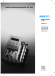
MAGIC
ISDN Telephone Hybrid System
MAGIC TOUCH
Hardware/Software Operating Manual
.
MAGIC
ISDN
Telephone
MAGIC
TOUCH
Hardware/Software
Hybrid
Operating
System
Manual
PAGE 3
.
A publication of:
AVT Audio Video Technologies GmbH
Nordostpark 12
D-90411 Nuernberg
Phone +49-911-5271-0
Fax +49-911-5271-100
Printed in Germany, 2004
© AVT Audio Video Technologies GmbH
All rights are reserved. Reproduction in
whole or in parts is prohibited without the
written consent of the copyright owner.
The information contained in this
publication is accurate to the best of our
knowledge. However, we disclaim any
liability resulting from the use of this
information and reserve the right to make
changes without notice.
Release Date:
(03.04)
PAGE 6
.
CONTENT
REGISTRATION
. . . . . . . . . . . . . . . . . . . . . . . . . . . . . . . . . . . . . . . . . . . . . . . . . . . . . . . . . . . . . . . . . . 11
INTRODUCTION
. . . . . . . . . . . . . . . . . . . . . . . . . . . . . . . . . . . . . . . . . . . . . . . . . . . . . . . . . . . . . . . . . 13
Text conventions
SAFETY
. . . . . . . . . . . . . . . . . . . . . . . . . . . . . . . . . . . . . . . . . . . . . . . . . . . . . . . . . . . . . . 13
. . . . . . . . . . . . . . . . . . . . . . . . . . . . . . . . . . . . . . . . . . . . . . . . . . . . . . . . . . . . . . . . . . . . . . . . . 15
Introduction
. . . . . . . . . . . . . . . . . . . . . . . . . . . . . . . . . . . . . . . . . . . . . . . . . . . . . . . . . . . . . . . . . . 15
General safety requirements
. . . . . . . . . . . . . . . . . . . . . . . . . . . . . . . . . . . . . . . . . . . . . . . . . . . . 15
Appereance of the safety instructions
Classification of danger
Symbols
CONSTRUCTION
2
SYSTEM DESCRIPTION
3
. . . . . . . . . . . . . . . . . . . . . . . . . . . . . . . . . . . . . . . . . . . . . . . . . . . . . . . . 16
. . . . . . . . . . . . . . . . . . . . . . . . . . . . . . . . . . . . . . . . . . . . . . . . . . . . . . . . . . . . . . . . . . . . . . 16
1
2.1
Functionality
. . . . . . . . . . . . . . . . . . . . . . . . . . . . . . . . . . . . . . . . . . . . . . . . . . . . . . . . . . . . . . . . . 17
. . . . . . . . . . . . . . . . . . . . . . . . . . . . . . . . . . . . . . . . . . . . . . . . . . . . . . . . . . . . 19
. . . . . . . . . . . . . . . . . . . . . . . . . . . . . . . . . . . . . . . . . . . . . . . . . . . . . . . . . . . . . . . . . 19
HARDWARE OPTIONS . . . . . . . . . . . . . . . . . . . . . . . . . . . . . . . . . . . . . . . . . . . . . . . . . . . . . . . . . . . . . 21
3.1
Magic Hybrid Keypad 4/7/12
3.2
Magic Hybrid Keypad PC
3.3
AES/EBU/ANALOGUE Module
3.4
Headset/Handset
3.5
MAGIC Hybrid Headset
4
. . . . . . . . . . . . . . . . . . . . . . . . . . . . . . . . . . . . . . . . . . . . 16
. . . . . . . . . . . . . . . . . . . . . . . . . . . . . . . . . . . . . . . . . . . . . . . . . . 21
. . . . . . . . . . . . . . . . . . . . . . . . . . . . . . . . . . . . . . . . . . . . . . . . . . . . . . 21
. . . . . . . . . . . . . . . . . . . . . . . . . . . . . . . . . . . . . . . . . . . . . . . . 22
. . . . . . . . . . . . . . . . . . . . . . . . . . . . . . . . . . . . . . . . . . . . . . . . . . . . . . . . . . . . . 23
SOFTWARE OPTIONS
. . . . . . . . . . . . . . . . . . . . . . . . . . . . . . . . . . . . . . . . . . . . . . . . . . . . . . . 23
. . . . . . . . . . . . . . . . . . . . . . . . . . . . . . . . . . . . . . . . . . . . . . . . . . . . . . . . . . . . . 25
4.1
MAGIC TOUCH LAN
4.2
MAGIC SCREENER
4.3
MAGIC TOUCH ADMIN/ADMIN LAN
5
. . . . . . . . . . . . . . . . . . . . . . . . . . . . . . . . . . . . . . . . . . . . . . . . . . . . . . . . . 25
. . . . . . . . . . . . . . . . . . . . . . . . . . . . . . . . . . . . . . . . . . . . . . . . . . . . . . . . . . . 26
PUTTING THE SYSTEM INTO OPERATION
5.1
Mounting
5.2
Connection to the mains supply
5.3
Alarm indication LEDs
5.4
Controls on the front panel
5.5
Changing the fuse
5.6
Cabling of the system
. . . . . . . . . . . . . . . . . . . . . . . . . . . . . . . . . . . . . . . . . 27
. . . . . . . . . . . . . . . . . . . . . . . . . . . . . . . . . . . . . . . . . . . . . 29
. . . . . . . . . . . . . . . . . . . . . . . . . . . . . . . . . . . . . . . . . . . . . . . . . . . . . . . . . . . . . . . . . . . . 29
. . . . . . . . . . . . . . . . . . . . . . . . . . . . . . . . . . . . . . . . . . . . . . . . . 29
. . . . . . . . . . . . . . . . . . . . . . . . . . . . . . . . . . . . . . . . . . . . . . . . . . . . . . . . . 29
. . . . . . . . . . . . . . . . . . . . . . . . . . . . . . . . . . . . . . . . . . . . . . . . . . . . . 30
. . . . . . . . . . . . . . . . . . . . . . . . . . . . . . . . . . . . . . . . . . . . . . . . . . . . . . . . . . . . . 30
. . . . . . . . . . . . . . . . . . . . . . . . . . . . . . . . . . . . . . . . . . . . . . . . . . . . . . . . . . 31
5.6.1
... without AES/EBU/ANALOGUE module
5.6.2
... with AES/EBU/ANALOGUE module
6
6.1
OPERATING MODES
. . . . . . . . . . . . . . . . . . . . . . . . . . . . . . . . . . . 32
. . . . . . . . . . . . . . . . . . . . . . . . . . . . . . . . . . . . . . 33
. . . . . . . . . . . . . . . . . . . . . . . . . . . . . . . . . . . . . . . . . . . . . . . . . . . . . . . . . . . . . . 35
Default operating mode
. . . . . . . . . . . . . . . . . . . . . . . . . . . . . . . . . . . . . . . . . . . . . . . . . . . . . . . . 35
6.1.1
... without AES/EBU/ANALOGUE module
. . . . . . . . . . . . . . . . . . . . . . . . . . . . . . . . . . . 35
6.1.2
... with the AES/EBU/ANALOGUE module
. . . . . . . . . . . . . . . . . . . . . . . . . . . . . . . . . . . 35
6.2
Multi fader operation with AES/EBU/Analogue module
. . . . . . . . . . . . . . . . . . . . . . . . . . . 37
PAGE 7
6.3
7
. . . . . . . . . . . . . . . . . . . . . . . . . . . . . . . . 38
. . . . . . . . . . . . . . . . . . . . . . . . . . . . . . . . . . . . . . . . . . . . . . . . . . . . . 39
MAGIC TOUCH SOFTWARE
7.1
Hardware requirements
7.2
Installation of the Windows PC Software MAGIC TOUCH
7.3
Configuration of the COM-Port
7.4
Quick installation
7.5
Operating elements of the MAGIC TOUCH Software
7.5.1
. . . . . . . . . . . . . . . . . . . . . . . . . . . . . . . . . . . . . . . . . . . . . . . . . . . . . . . 39
. . . . . . . . . . . . . . . . . . . . . . . . . 39
. . . . . . . . . . . . . . . . . . . . . . . . . . . . . . . . . . . . . . . . . . . . . . . . . 41
. . . . . . . . . . . . . . . . . . . . . . . . . . . . . . . . . . . . . . . . . . . . . . . . . . . . . . . . . . . . . 43
Operation keys
. . . . . . . . . . . . . . . . . . . . . . . . . . . . . . 44
. . . . . . . . . . . . . . . . . . . . . . . . . . . . . . . . . . . . . . . . . . . . . . . . . . . . . . . . . . . . 45
7.5.1.1
PRE TALK SRC (Pre Talk Source)
7.5.1.2
GLOBAL (Drop All, Lock)
7.5.1.3
Forw. Call (Call forwarding)
7.5.1.4
Manual Call
. . . . . . . . . . . . . . . . . . . . . . . . . . . . . . . . . . . . . . . . . . . . . . . . . . . . . . . . . . . 46
7.5.1.5
Information
. . . . . . . . . . . . . . . . . . . . . . . . . . . . . . . . . . . . . . . . . . . . . . . . . . . . . . . . . . . 49
7.5.2
Line functions
. . . . . . . . . . . . . . . . . . . . . . . . . . . . . . . . . . . . . . . . 45
. . . . . . . . . . . . . . . . . . . . . . . . . . . . . . . . . . . . . . . . . . . . . . . 45
. . . . . . . . . . . . . . . . . . . . . . . . . . . . . . . . . . . . . . . . . . . . . 45
. . . . . . . . . . . . . . . . . . . . . . . . . . . . . . . . . . . . . . . . . . . . . . . . . . . . . . . . . . . . . 51
7.5.2.1
Line functions without existing connection
7.5.2.2
Line functions with existing connection or incoming call
7.5.2.3
Level Meter Display
7.5.2.4
Level setting
7.5.2.5
Time information . . . . . . . . . . . . . . . . . . . . . . . . . . . . . . . . . . . . . . . . . . . . . . . . . . . . . . . 52
. . . . . . . . . . . . . . . . . . . . . . . . . . . . . . . . 51
. . . . . . . . . . . . . . . . . . . . 51
. . . . . . . . . . . . . . . . . . . . . . . . . . . . . . . . . . . . . . . . . . . . . . . . . . . . 52
. . . . . . . . . . . . . . . . . . . . . . . . . . . . . . . . . . . . . . . . . . . . . . . . . . . . . . . . . . . 52
7.6
Menu File → Exit
7.7
Configuration Menu
. . . . . . . . . . . . . . . . . . . . . . . . . . . . . . . . . . . . . . . . . . . . . . . . . . . . . . . . . . . . . 54
. . . . . . . . . . . . . . . . . . . . . . . . . . . . . . . . . . . . . . . . . . . . . . . . . . . . . . . . . . 55
7.7.1
COM Port Submenu
. . . . . . . . . . . . . . . . . . . . . . . . . . . . . . . . . . . . . . . . . . . . . . . . . . . . . . . 55
7.7.2
PC Keypad Submenu
. . . . . . . . . . . . . . . . . . . . . . . . . . . . . . . . . . . . . . . . . . . . . . . . . . . . . . 56
7.7.3
System Submenu
. . . . . . . . . . . . . . . . . . . . . . . . . . . . . . . . . . . . . . . . . . . . . . . . . . . . . . . . . . 58
7.7.3.1
General
7.7.3.2
Slave Search
7.7.3.3
Database settings
7.7.3.4
S0 Line
7.7.3.5
VIP Line
7.7.3.6
Night Mode
7.7.3.7
MSN
7.7.3.8
Quick Dial
7.7.3.9
Audio Level
7.7.3.10
Hold Signal Recording/Source
7.7.3.11
Signal Processing
7.7.3.12
Security
7.7.3.13
LAN Settings
7.7.3.14
Audio Lines (Configuration of the Audio interfaces)
7.7.3.15
Relays (Relays settings)
7.7.3.16
Messaging
7.7.4
7.7.4.1
7.8
PAGE 8
Multi-Pre-Talk with AES/EBU/Analogue module
. . . . . . . . . . . . . . . . . . . . . . . . . . . . . . . . . . . . . . . . . . . . . . . . . . . . . . . . . . . . . . . 58
. . . . . . . . . . . . . . . . . . . . . . . . . . . . . . . . . . . . . . . . . . . . . . . . . . . . . . . . . . . 69
. . . . . . . . . . . . . . . . . . . . . . . . . . . . . . . . . . . . . . . . . . . . . . . . . . . . . . . 70
. . . . . . . . . . . . . . . . . . . . . . . . . . . . . . . . . . . . . . . . . . . . . . . . . . . . . . . . . . . . . . . . 73
. . . . . . . . . . . . . . . . . . . . . . . . . . . . . . . . . . . . . . . . . . . . . . . . . . . . . . . . . . . . . . 76
. . . . . . . . . . . . . . . . . . . . . . . . . . . . . . . . . . . . . . . . . . . . . . . . . . . . . . . . . . . 79
. . . . . . . . . . . . . . . . . . . . . . . . . . . . . . . . . . . . . . . . . . . . . . . . . . . . . . . . . . . . . . . . . 81
. . . . . . . . . . . . . . . . . . . . . . . . . . . . . . . . . . . . . . . . . . . . . . . . . . . . . . . . . . . . . 84
. . . . . . . . . . . . . . . . . . . . . . . . . . . . . . . . . . . . . . . . . . . . . . . . . . . . . . . . . . . 86
. . . . . . . . . . . . . . . . . . . . . . . . . . . . . . . . . . . . . . . . . . . 87
. . . . . . . . . . . . . . . . . . . . . . . . . . . . . . . . . . . . . . . . . . . . . . . . . . . . . . . 89
. . . . . . . . . . . . . . . . . . . . . . . . . . . . . . . . . . . . . . . . . . . . . . . . . . . . . . . . . . . . . . . 92
. . . . . . . . . . . . . . . . . . . . . . . . . . . . . . . . . . . . . . . . . . . . . . . . . . . . . . . . . . 95
. . . . . . . . . . . . . . . . . . . . . . . . 98
. . . . . . . . . . . . . . . . . . . . . . . . . . . . . . . . . . . . . . . . . . . . . . . . 102
. . . . . . . . . . . . . . . . . . . . . . . . . . . . . . . . . . . . . . . . . . . . . . . . . . . . . . . . . . . . 104
Presets Submenu
. . . . . . . . . . . . . . . . . . . . . . . . . . . . . . . . . . . . . . . . . . . . . . . . . . . . . . . . . 107
Manage Presets
Menu Administration
. . . . . . . . . . . . . . . . . . . . . . . . . . . . . . . . . . . . . . . . . . . . . . . . . . . . . . . 108
. . . . . . . . . . . . . . . . . . . . . . . . . . . . . . . . . . . . . . . . . . . . . . . . . . . . . . . . 110
7.8.1
Registration Submenu
. . . . . . . . . . . . . . . . . . . . . . . . . . . . . . . . . . . . . . . . . . . . . . . . . . . . . 110
7.8.2
S0 Interface Reset Submenu
. . . . . . . . . . . . . . . . . . . . . . . . . . . . . . . . . . . . . . . . . . . . . . . . 112
7.8.3
List TCP/IP Connections Submenu
7.8.4
System Panel Submenu
7.8.5
Software Download Submenu
7.9
Extras Menu
. . . . . . . . . . . . . . . . . . . . . . . . . . . . . . . . . . . . . . . . . . 113
. . . . . . . . . . . . . . . . . . . . . . . . . . . . . . . . . . . . . . . . . . . . . . . . . . . . 114
. . . . . . . . . . . . . . . . . . . . . . . . . . . . . . . . . . . . . . . . . . . . . . 115
. . . . . . . . . . . . . . . . . . . . . . . . . . . . . . . . . . . . . . . . . . . . . . . . . . . . . . . . . . . . . . . . . 117
7.9.1
Submenu Center Window
7.9.2
Messaging Menu
. . . . . . . . . . . . . . . . . . . . . . . . . . . . . . . . . . . . . . . . . . . . . . . . . . 117
. . . . . . . . . . . . . . . . . . . . . . . . . . . . . . . . . . . . . . . . . . . . . . . . . . . . . . . . . . 118
7.9.2.1
Submenu Write Pop-up Message
7.9.2.2
Show Pop-up Message
7.10
Menu Night Mode
7.11
Help Menu
7.11.1
7.12
. . . . . . . . . . . . . . . . . . . . . . . . . . . . . . . . . . . . . . . . . 118
. . . . . . . . . . . . . . . . . . . . . . . . . . . . . . . . . . . . . . . . . . . . . . . . . . 118
. . . . . . . . . . . . . . . . . . . . . . . . . . . . . . . . . . . . . . . . . . . . . . . . . . . . . . . . . . . . 120
. . . . . . . . . . . . . . . . . . . . . . . . . . . . . . . . . . . . . . . . . . . . . . . . . . . . . . . . . . . . . . . . . . 121
About MAGIC TOUCH Submenu ...
What do I have to set, if I...
. . . . . . . . . . . . . . . . . . . . . . . . . . . . . . . . . . . . . . . . . 121
. . . . . . . . . . . . . . . . . . . . . . . . . . . . . . . . . . . . . . . . . . . . . . . . . . . . 122
7.12.1
... I want to use MAGIC TOUCH LAN?
7.12.2
... I want to use MAGIC SCREENER?
7.12.3
... I want to use the MAGIC Hybrid Keypad of the PC?
7.12.4
... I want to use the MAGIC Hybrid keypad as a redundant mode?
8
OPTION: MAGIC HYBRID KEYPAD PC
. . . . . . . . . . . . . . . . . . . . . . . . . . . . . . . . . . . . . . . . 123
. . . . . . . . . . . . . . . . . . . . . . . . . 124
. . . . . . . . . . . . . . 124
. . . . . . . . . . . . . . . . . . . . . . . . . . . . . . . . . . . . . . . . . . . . 125
8.1
Working with the MAGIC Hybrid Keypad
8.2
Function of the keypad
9
. . . . . . . . . . . . . . . . . . . . . . . . . . . . . . . . . . . . . . 122
. . . . . . . . . . . . . . . . . . . . . . . . . . . . . . . . . . . . . . 125
. . . . . . . . . . . . . . . . . . . . . . . . . . . . . . . . . . . . . . . . . . . . . . . . . . . . . . . . 126
OPTION: MAGIC HYBRID KEYPAD
. . . . . . . . . . . . . . . . . . . . . . . . . . . . . . . . . . . . . . . . . . . . . . . . 129
9.1
Working with the MAGIC Hybrid Keypad
9.2
LCD-Display
. . . . . . . . . . . . . . . . . . . . . . . . . . . . . . . . . . . . . . 131
. . . . . . . . . . . . . . . . . . . . . . . . . . . . . . . . . . . . . . . . . . . . . . . . . . . . . . . . . . . . . . . . 131
9.2.1
Configuration of operating mode
. . . . . . . . . . . . . . . . . . . . . . . . . . . . . . . . . . . . . . . . . . . . 132
9.2.2
Entering the telephone number
9.2.3
Level meter . . . . . . . . . . . . . . . . . . . . . . . . . . . . . . . . . . . . . . . . . . . . . . . . . . . . . . . . . . . . . . . 132
9.2.4
ISDN error messages
. . . . . . . . . . . . . . . . . . . . . . . . . . . . . . . . . . . . . . . . . . . . . 132
. . . . . . . . . . . . . . . . . . . . . . . . . . . . . . . . . . . . . . . . . . . . . . . . . . . . . . 133
9.3
Function of the keypad
9.4
Programming of the quick dial keys
. . . . . . . . . . . . . . . . . . . . . . . . . . . . . . . . . . . . . . . . . . . . 136
9.5
Programming of the call forwarding
. . . . . . . . . . . . . . . . . . . . . . . . . . . . . . . . . . . . . . . . . . . . 136
A1
ALARMS
A2
ISDN ERROR MESSAGES
A3
SYSTEM LIMITS
A4
INTERFACES
. . . . . . . . . . . . . . . . . . . . . . . . . . . . . . . . . . . . . . . . . . . . . . . . . . . . . . . . 134
. . . . . . . . . . . . . . . . . . . . . . . . . . . . . . . . . . . . . . . . . . . . . . . . . . . . . . . . . . . . . . . . . . . . . . 137
. . . . . . . . . . . . . . . . . . . . . . . . . . . . . . . . . . . . . . . . . . . . . . . . . . . . . . . . 139
. . . . . . . . . . . . . . . . . . . . . . . . . . . . . . . . . . . . . . . . . . . . . . . . . . . . . . . . . . . . . . . . 141
. . . . . . . . . . . . . . . . . . . . . . . . . . . . . . . . . . . . . . . . . . . . . . . . . . . . . . . . . . . . . . . . . . . 143
A4.1
S0-Interface
A4.2
RS232C Interface
A4.3
TTL USER I/O Interface
. . . . . . . . . . . . . . . . . . . . . . . . . . . . . . . . . . . . . . . . . . . . . . . . . . . . . . . 145
A4.4
LSD (Keypad) Interface
. . . . . . . . . . . . . . . . . . . . . . . . . . . . . . . . . . . . . . . . . . . . . . . . . . . . . . 146
A4.5
HSD (Relay) Interface
A4.6
Audio Interface
A4.7
Handset/MAGIC Hybrid Headset Socket
A4.8
Audios interfaces on the optional AES/EBU/ANALOGUE Module
A4.8.1
. . . . . . . . . . . . . . . . . . . . . . . . . . . . . . . . . . . . . . . . . . . . . . . . . . . . . . . . . . . . . . . . . 144
. . . . . . . . . . . . . . . . . . . . . . . . . . . . . . . . . . . . . . . . . . . . . . . . . . . . . . . . . . . . 145
. . . . . . . . . . . . . . . . . . . . . . . . . . . . . . . . . . . . . . . . . . . . . . . . . . . . . . . . . 146
. . . . . . . . . . . . . . . . . . . . . . . . . . . . . . . . . . . . . . . . . . . . . . . . . . . . . . . . . . . . . 147
AES/EBU Audio Interface
. . . . . . . . . . . . . . . . . . . . . . . . . . . . . . . . . . . . . . . 147
. . . . . . . . . . . . . . . . 148
. . . . . . . . . . . . . . . . . . . . . . . . . . . . . . . . . . . . . . . . . . . . . . . . . 148
PAGE 9
A4.8.2
A4.9
Analogue Audio Interface
Extension Bus (internal data bus and control bus)
. . . . . . . . . . . . . . . . . . . . . . . . . . . . . . . . 150
A5
TECHNICAL DATA: MAGIC ISDN TELEPHONE HYBRID
A6
TECHNICAL DATA: MAGIC HYBRID KEYPAD
MAGIC Hybrid Keypad
A6.2
LCD Display (only MAGIC Hybrid Keypad 4/7/12)
A6.3
Connecting cable
A6.4
Power supply connector to the power supply set
A6.5
Connection to MAGIC Telephone Hybrid
A6.6
Keypad data interface to the keypad
A6.7
External power supply
GENERAL
. . . . . . . . . . . . . . . . . . . . . . . . . . . . . . . . . . . . . . . . . . . . . . . . . . . . . . 153
. . . . . . . . . . . . . . . . . . . . . . . . . . . . . 153
. . . . . . . . . . . . . . . . . . . . . . . . . . . . . . . . . . . . . . . . . . . . . . . . . . . . . . . . . . . . 153
. . . . . . . . . . . . . . . . . . . . . . . . . . . . . . . . 154
. . . . . . . . . . . . . . . . . . . . . . . . . . . . . . . . . . . . . . . 154
. . . . . . . . . . . . . . . . . . . . . . . . . . . . . . . . . . . . . . . . . . . 154
. . . . . . . . . . . . . . . . . . . . . . . . . . . . . . . . . . . . . . . . . . . . . . . . . . . . . . . 155
. . . . . . . . . . . . . . . . . . . . . . . . . . . . . . . . . . . . . . . . . . . . . . . . . . . . . . . . . . . . . . . . . . . . . 157
A7.1
Ordering numbers
A7.2
Included in delivery
A7.3
Declaration of conformity
INDEX
. . . . . . . . . . . . . . . . . . . . . . . . . . . . 151
. . . . . . . . . . . . . . . . . . . . . . . . . . . . . . . . . . . . . 153
A6.1
A7
PAGE 10
. . . . . . . . . . . . . . . . . . . . . . . . . . . . . . . . . . . . . . . . . . . . . . . . . 149
. . . . . . . . . . . . . . . . . . . . . . . . . . . . . . . . . . . . . . . . . . . . . . . . . . . . . . . . . . . 157
. . . . . . . . . . . . . . . . . . . . . . . . . . . . . . . . . . . . . . . . . . . . . . . . . . . . . . . . . 158
. . . . . . . . . . . . . . . . . . . . . . . . . . . . . . . . . . . . . . . . . . . . . . . . . . . . . 158
. . . . . . . . . . . . . . . . . . . . . . . . . . . . . . . . . . . . . . . . . . . . . . . . . . . . . . . . . . . . . . . . . . . . . . . . 159
R e g i s t r a t i o n
REGISTRATION
L
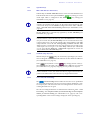
If you are not already registered take a moment to read this.
Registered users automatically receive messages as soon as new software or
other news on the MAGIC ISDN Telephone Hybrid is available.
The registration is done via the internet
http://www.avt-nbg.de
Then switch to Service and Software Registration.
Enter MAGIC ISDN Telephone Hybrid when asked "Which of the following
products do you use (select one or more)?".
Afterwards define your own User name and your own Password 1.
As contact address enter at least your Email address.
Then send the registration.
After a short time you will receive the confirmation.
1
Take care to remember your user name and password. The password is not known to us. In case
you have forgotten your password, send us a short email with your user name. We will cancel your
registry and you are able to register again.
PAGE 11
R e g i s t r a t i o n
PAGE 12
I n t r o d u c t i o n
INTRODUCTION
The MAGIC ISDN Telephone Hybrid system enables the forwarding of telephone calls to analogue or optional AES/EBU Audio interfaces. Since the system is based on a modular construction, it is possible to expand it as desired.
The basic system supports a simultaneous Hybrid function up to three or four
callers, as well as call forwarding to a selected number. With an extension system four additional channels are available, which can be used for additional
callers or other call forwarding numbers. Besides, each system has an additional analogue interface. The maximum build supports up to 16 callers simultaneously On Air.
In contrast to previous systems, great emphasis has been put on using as little
external wiring as possible. The system is able to realise functions such as digital mixing of callers, digital Mix Minus, Echo Cancelling, AGC, etc.
The configuration and operation of the system is made via the Windows application MAGIC TOUCH, included in the delivery of the Master system. The
software is optimised for operation with a Touch screen.
L
Urgent users can find the essential basic configurations in „Quick installation“ CHAPTER 7.4, page 43.
Please also pay attention to the chapter: What do I have to set, if...,
... I want to use MAGIC TOUCH LAN? (Page 122)
... I want to use MAGIC SCREENER? (Page 123)
... I want to use the MAGIC Hybrid Keypad of the PC? (Page 124)
... I want to use the MAGIC Hybrid keypad as a redundant mode? (Page 124)
Text conventions
To increase the readability of the document, the following text conventions
are used throughout the document.
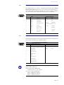
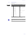
TAB. 1
TEXT CONVENTIONS
Formatting
Important terms are displayed in bold.
Descriptions and software functions are highlighted in bold italic.
PAGE 13
I n t r o d u c t i o n
PAGE 14
S a f e t y
SAFETY
Introduction
The unit described is designed to the latest technical parameters and complies
with all national and international safety requirements. It operates with a high
level of operational safety resulting from long development experience and
stringent quality control in our company.
In normal operation this equipment is safe.
There are, however, some potential sources of danger that cannot be completely eliminated.
This Operator Manual therefore contains basic safety instructions that must
be observed during system configuration and operation. The Operator Manual must be read before the system is used and the current version of the document must always be kept close to the equipment.
General safety requirements
In order to keep the technically unavoidable residual risk to a minimum it is
imperative to observe the following rules:
– Transport, storage and operation of the unit/system must be under the
permissible conditions only.
– Installation, configuration and disassembly must be carried out only by
trained personnel and with reference to the respective documentation.
– The system must be operated by knowledgeable and authorised users
only.
– The system/unit must not be operated unless it is in good working order.
– Any conversions or alterations to the system or parts of the system (including the software) must be carried out by qualified personnel from the manufacturer or by expert personnel authorised by our company.
All alterations carried out by other persons lead to a complete exemption
from liability.
– The removal or disabling of safety measures, the correction of faults and
errors, and the maintenance of equipment must be carried out by specially
qualified personnel only.
– Non-system software is used at one‘s own risk. The use/installation of
non-system software can adversely affect the normal functioning of the
system.
– Only use tested and virus-free data carriers.
PAGE 15
S i c h e r h e i t
Appereance of the safety instructions
All safety instructions include a Symbol that classifies the danger and a Textblock, that contains descriptions of the type and cause of the danger, the consequences of ignoring the safety instruction and the measures that can be
taken to minimise the danger.
Symbol
Type and cause of danger
Possible consequences of ignoring the safety instruction.
Measures to minimise the danger.
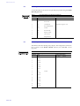
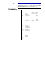
Classification of danger
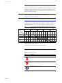
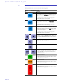
There are five class of safety instructions "danger", "warning", "caution", "notice" and "important". The classification is shown in the following table. .
possible
likely
definite
possible
likely
possible
likely
definite
Material damage 1 Fault 2
Minor
injury
possible
likely
definite
possible
Serious
injury
likely
classification
Death
definite
Result
SIGNAL WORDS AND EFFECTS WHEN IGNORING THE SAFETY INSTRUCTIONS
definite
TAB. 2
DANGER 3
WARNING
CAUTION
NOTICE
IMPORTANT
1
damage to product or product environment
2
considerable impairment to operation
3
this danger class is not required for MAGIC ISDN Telephone Hybrid.
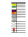
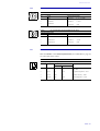
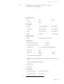
Symbols
Following symbols are used:
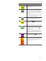
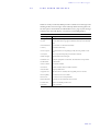
TAB. 3
Symbol
1
,
L
PAGE 16
SYMBOLS
common usage
DANGER, WARNING: Warning about dangerous electrical voltage
CAUTION, NOTICE: Common warning about a danger or wrong operation
IMPORTANT: Important notice or tip
C o n s t r u c t i o n
1
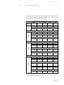
CONSTRUCTION
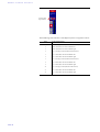
The functions of the MAGIC ISDN Telephone Hybrid are included in a single
unit. The system is designed for mounting in a 19’’ rack (1 HE).
The system can be expanded with the AES/EBU/Analogue module. This module provides two additional analogue inputs/outputs as well as two digital
inputs/outputs (physically: one digital AES/EBU interface).
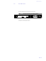
FIG. 1
FRONT VIEW: MAGIC ISDN TELEPHONE HYBRID
MAGIC ISDN TELEPHONE HYBRID
HANDSET
POWER
CONNECT
ALARM
MADE IN GERMANY
Status LEDs
Handset socket for MAGIC Hybrid Headset
PAGE 17
C o n s t r u c t i o n
PAGE 18
S y s t e m
2
SYSTEM
D e s c r i p t i o n
DESCRIPTION
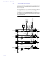
The block diagram of the system is shown in Fig. 2.
FIG. 2
THE BLOCK DIAGRAM OF THE MAGIC ISDN TELEPHONE HYBRID
RS 232C
Line
interfaces
basic construction
TTL USER I/O
ISDN Module
HSD (Relay)
2 x S0
LSD (Keypad)
Channel 1
AES/EBU
Channel 2
AES/EBU
ANALOGUE
Module
Channel 1
Analogue
Channel 2
DSP
- Echo Canceller
- N-1, AGC
- Digital Mixing
(Option)
Audio codec
Standard
Audio
interface
Handset
- Analogue Audio
- G.711 Codec
Audio (CMD)
Extension Bus
2.1
Functionality
The Telephone Hybrid system has a maximum of four MAGIC ISDN Telephone Hybrids, which are connected via the Extension Bus. Therefore a maximum of 8 S0 interfaces as well as 4 analogue Audio inputs and Audio outputs
are available to the user. Additionally, a Handset or MAGIC Hybrid Headset can
be connected to the front side of the system.
With the optional AES/EBU/ANALOGUE Module, any part of the system can
be extended by two Audio inputs/outputs.
Via the Telephone Hybrid system - depending on the build - up to 16 callers
can be put On Air or in Pre Talk simultaneously. Additionally, there are configurable call forwarding possibilities.
For each caller, a digital Echo Canceller is available. This echo canceller is necessary to suppress disturbing echos when the caller is using a normal analogue telephone.
Likewise, the Automatic Gain Control (AGC) can be switched on for each
caller.
To suppress disturbing noise from callers who are currently not speaking, the
Expander can be activated.
In the conference mode there is the possibility of mixing all callers digitally
PAGE 19
S y s t e m
D e s c r i p t i o n
and connecting the mixed signal to one conference. The callers get the digitally generated Mix Minus signal.
Three Relays (HSD interface) are available for external signalling.
Their configuration and operation is made by the MAGIC TOUCH Windows
software included in the delivery.
PAGE 20
H a r d w a r e
3
HARDWARE
3.1
Magic Hybrid Keypad 4/7/12
O p t i o n s
OPTIONS
Optionally, the MAGIC Hybrid Keypad 4/7/12 can be connected to the system
in parallel to the operating software. This seperate keypad with illuminated
display, enables a (limited) operation of the system for a maximum of four,
seven or 12 callers, in case the PC crashes.
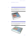
FIG. 3
3.2
MAGIC HYBRID KEYPAD 4
Magic Hybrid Keypad PC
Instead of using Touch screens, the system can also be operated independently via the optional MAGIC Hybrid Keypad PC for a maximum of 7 callers.
The keypad can be connected directly to the PC.
FIG. 4
MAGIC HYBRID KEYPAD PC
PAGE 21
H a r d w a r e
O p t i o n s
3.3
AES/EBU/ANALOGUE Module
The optional AES/EBU/ANALOG Module extends the system by two further
analogue or two digital AES/EBU inputs and outputs (switchable). Via the
MAGIC TOUCH software, each Audio interface can be configured as desired
to the greatest possible extend.
L
Subsequent installation of the module can only be made in our factory.
Therefore, three analogue inputs (Audio interface already existing in the system + two further modules) and three analogue Audio outputs are available
when selecting the analogue input Audio interface (see Fig. 5). The two analogue outputs of the modules are, additionally, activated in parallel, on the
digital Audio interface of each module.
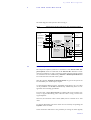
FIG. 5
AUDIO INTERFACES WHEN SELECTING THE ANALOGUE INPUT
If the digital inputs of the module are selected (see Fig. 6), one analogue and
two digital Audio inputs are available as well as two digital and one analogue
output. The digital outputs of the module are additionally activated in parallel to the analogue Audio interfaces of the module. The digital input as well
as the output have their own sample rate converter. The word clock can be
read or fed in via the BNC connector.
Please note that the two inputs/outputs are physically one AES/EBU interface. The outputs are always connected in parallel.
FIG. 6
L
Maximum number of Audio interfaces
The maximum number of available Audio interfaces depends on the number
of B channels. The sum of the Audio interfaces and B channels (visible channels + call forwardings) is limited to 24 (e.g. 12 Audio interfaces and 12 B
channels). The maximum number of Audio interfaces can be twelve 1 in the
maximum build (see CHAPTER A3, page 141).
1
PAGE 22
AUDIO INTERFACES WHEN SELECTING THE DIGITAL INPUT
Until release 3.0, a max. of only seven Audio interfaces are available.
H a r d w a r e
3.4
O p t i o n s
Headset/Handset
The MAGIC ISDN Telephone Hybrid has an Audio connection for a Headset/Handset. Via this headset/handset e.g., the Pre Talk can be carried out.
Switching between the handset and an Audio input of the system is made via
the MAGIC TOUCH, MAGIC TOUCH LAN or the MAGIC Hybrid Keypad.
If the handset is used, a separate screener place can be implemented. In this
case, the presenter uses his headset for the Pre Talk. The software is implemented in such a way that faulty operation between presenter and screener
place is not possible.
The supply line between headset and Hybrid system can be extended up to 20
meters, since the Audio interface is implemented as an electronically balanced
interface.
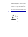
3.5
MAGIC Hybrid Headset
FIG. 7
MAGIC HYBRID HEADSET
For persons who are telephoning often, the MAGIC Hybrid Headset can be
used instead of the handset.
PAGE 23
H a r d w a r e
PAGE 24
O p t i o n s
S o f t w a r e
4
SOFTWARE
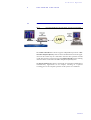
4.1
MAGIC TOUCH LAN
FIG. 8
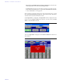
O p t i o n s
OPTIONS
USAGE OF THE MAGIC TOUCH & MAGIC TOUCH LAN SOFTWARE
The MAGIC TOUCH LAN software supports independent operation of MAGIC ISDN Telephone Hybrid systems via the local Ethernet network. The application can be used on any PC connected to the LAN. The operation is made
via the TCP/IP protocol and accesses to the MAGIC TOUCH software running
on the PC that is connected to the ISDN Telephone Hybrid System.
The MAGIC TOUCH LAN software can be used on a maximum of seven places
simultaneously. Applications are for example, screening via a separate
screening place or the complete operation of the system via a technician.
PAGE 25
S o f t w a r e
O p t i o n s
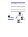
4.2
MAGIC SCREENER
The MAGIC SCREENER database supported, screener software enables a
connection between the MAGIC TOUCH control software, the feature rich
screening and the adminsitration of all callers. Also, remote control such as dialling or switching of single lines of the ISDN Telephone Hybrid, is possible .
The connection between the MAGIC TOUCH and the MAGIC SCREENER
software is established via the LAN with the help of the TCP/IP protocol. The
caller data is stored in a central data base to which all applications have access.
In principal, the MAGIC SCREENER can be installed as many times as desired
in the local network. Therefore, simultaneous screening of several screening
places is possible.
FIG. 9
PAGE 26
USAGE OF THE MAGIC TOUCH & MAGIC SCREENING SOFTWARE
S o f t w a r e
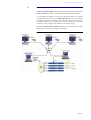
4.3
O p t i o n s
MAGIC TOUCH ADMIN/ADMIN LAN
The MAGIC TOUCH ADMIN software enables the administration of up to four
MAGIC TOUCH LAN clients, who use a common Central Hybrid System.
For each studio, the number of caller lines and Audio interfaces is assigned
via a Preset. Each studio sees, on its MAGIC TOUCH LAN screen, only the lines
assigned. An important advantage of this solution is the flexible assignment
of a studio: therefore, a particular show can be broadcast from any studio
without any major changes to the PABX or of the Audio wiring.
Optionally, MAGIC TOUCH ADMIN LAN software is available, which can be
used, e.g. for a common screening of all caller lines.
FIG. 10
USE OF THE MAGIC TOUCH & MAGIC SCREENING SOFTWARE
PAGE 27
S o f t w a r e
PAGE 28
O p t i o n s
P u t t i n g
i n t o
o p e r a t i o n
5
PUTTING THE SYSTEM INTO OPERATION
5.1
Mounting
With its dimensions (W × H × D) of 439 mm × 44,5 mm (1 HE) × 300 mm, the
MAGIC ISDN Telephone Hybrid System can be operated as a table-top device
or can be mounted in 19’’ racks. Additionally, mounting brackets are provided for an ETSI rack.
During the installation, care should be taken to ensure that the bending radius
of the cables is always greater than the minimum allowed value.
If the MAGIC ISDN Telephone Hybrid is installed in a rack, it should be ensured
that sufficient ventilation is provided. It is recommended that approx. 3 cm
clearance is left next to the openings. As a rule, the ambient temperature of the
system should not lie outside the range +5° C to +40° C. These limits are of particular importance if the system is inserted in a rack.
During operation, the humidity must lie between 5% and 85%.
L
Incorrect ambient temperature and humidity can lead to equipment failure.
Operation of the unit outside the above limits invalidates the warranty.
The operation of the system must therefore lie within the specified limits.
5.2
Connection to the mains supply
The system can be operated with a mains voltage between 90 V and 253 V and
a mains frequency between 45 Hz and 65 Hz. The power consumption has a
maximum value of approx. 30W. In accordance with safety regulations, the
housing must be earthed (grounded). This earthing is normally realised via
the protective earth (or ground) conductor of the mains cable. If the mains cable does not have a protective conductor, however, the device must be
earthed via its earthing bolt.
1
Dangerous voltage in case of inadequate earthing!
If the earthing is defective or lacking, hazardous voltages can be present on
the housing in the event of a fault.
Do not use extension cables without an earthing conductor!
In case of doubt provide additional earthing!
After switching the system on, the green POWER LED should light up. An internal reset is then triggered. After approx. 45 seconds, the system is ready for
operation, when the red LED ALARM stops blinking.
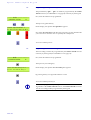
5.3
Alarm indication LEDs
The MAGIC ISDN Telephone Hybrid has three LEDs for status indication.
PAGE 29
P u t t i n g
i n t o
o p e r a t i o n
5.4
(1)
POWER
green
Lights up when system is ready for operation.
(2)
CONNECT
green
Lights up if at least one telephone connection is established.
(3)
ALARM
red
Lights up if a fault has occurred in the unit. The Windows PC software
provides more detailed information about the error (see CHAPTER A1,
page 137).
Controls on the front panel
The system has no controls on the front panel; there is only a socket for the
Handset or the MAGIC Hybrid Headset (not included in the delivery).
5.5
Changing the fuse
The mains system is protected by a fuse, which is soldered into the system.
Only qualified personnel are allowed to change the fuse.
1
PAGE 30
Dangerous voltage when the equipment is opened!
The unit should only be repaired by experienced technicians or our expert
personnel.
P u t t i n g
5.6
i n t o
o p e r a t i o n
Cabling of the system
The following figures show with help of examples, the general cabling of the
system.
The assignment of the Audio and relay interfaces are only an example. The assignment can be configured in accordance with your personal requirements
(see CHAPTER 7.7.3.14, page 98).
L
You must not forget to connect the included dongle(s) to the Slave system(s),
since the basic function of a slave is configured by this. Please pay attention
to the numbering of each dongle.
When using a Master system, no dongle has to be connected.
L
If a combination of Master and Slave system is used, not all available S0 connections need to be connected to the ISDN network. If you are working with
a maximum of only 4 B channels, but also want to use the Pre Talk function,
you only need to connect 2 S0 interfaces to the Master system.
PAGE 31
P u t t i n g
i n t o
o p e r a t i o n
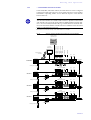
5.6.1
... without AES/EBU/ANALOGUE module
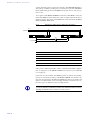
In this wiring exemple (Fig. 11, page 32) a Pre Talk, a separate Hold and an On
Air Audio interface are used. A fourth Audio interface is also available in the
Slave 3 System for, e.g., an alternative On Air or Pre Talk Line (see CHAPTER 7.7.3.1.2, page 60).
The function of the relays can be programmed as desired (see CHAPTER
7.7.3.15, page 102). Useful is e.g., the use of a relay for incoming calls and for
operating the mixer as soon as a line is switched to Pre Talk or On Air.
For redundancy purposes, a MAGIC Hybrid Keypad can be connected in parallel to the Master System. This keypad ensures that if the PC crashes, the caller
lines can still be operated.
FIG. 11
WIRING OF THE MAXIMUM SYSTEM BUILD WITHOUT AES/EBU/ANALOGUE MODULE
Audio
input
presenter
and
programme
without
caller
Option: MAGIC
Hybrid Keypad
Audio
output:
Number
of all
ON AIR
callers
PC with
Touchscreen
Relay
Relay
ON AIR PRE TALK
Relay
CALL
S0 1
POWER 115/230V
MASTER
0 I
RS232C
LSD
HSD
OUTPUT CMD
mains power supply
INPUT
Audioinput
PRE TALK
Audio
S0 3
output
PRE TALK
Option: Handset
or Headset
POWER 115/230V
0 I
RS232C
LSD
Dongle: Slave 1
INPUT
Audio
input
HOLD
3 further Relays
Audio
output
HOLD
S0 5
POWER 115/230V
SLAVE 2
0 I
RS232C
LSD
HSD
INPUT
further
Audio
input
3 further Relays
further
Audio
output
Dongle: Slave 2
S0 7
POWER 115/230V
SLAVE 3
0 I
1
USER I/O
RS232C
LSD
HSD
3 further Relays
PAGE 32
Dongle: Slave 3
S0 8
So
EXTENSION BUS
OUTPUT CMD
mains power supply
2
EXTENSION BUS
OUTPUT CMD
mains power supply
S0 6
So
1
USER I/O
2
EXTENSION BUS
HSD
OUTPUT CMD
mains power supply
S0 4
So
1
USER I/O
2
EXTENSION BUS
no Dongle
SLAVE 1
So
1
USER I/O
S0 2
INPUT
2
Extension BusCable
P u t t i n g
5.6.2
i n t o
o p e r a t i o n
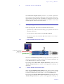
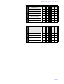
... with AES/EBU/ANALOGUE module
Via the AES/EBU/ANALOG module, the Audio interfaces can be configured
as desired. Possible applications for several Audio interfaces can be found in
CHAPTER 6 "Operating Modes" and in different chapters of the MAGIC
TOUCH Software.
L
Maximum number of Audio interfaces
The maximum number of available Audio interfaces depends on the number
of B channels. The sum of the Audio interfaces and B channels (visible channels + calls forwarded) is limited to 24 (e.g. 12 Audio interfaces and 12 B channels). The maximum number of Audio interfaces is twelve 1 in the maximum
build (see CHAPTER A3, page 141).
1
Until release 3.0 a maximum of only seven Audio interfaces is available.
FIG. 12
WIRING OF THE SYSTEM WITH AES/EBU/ANALOGUE MODULE
Option: Handset
or Headset
PRE TALK
PC with
Touchscreen
PRE TALK
ON AIR
HOLD or PRE TALK
ON AIR
HOLD or PRE TALK
ON AIR
HOLD or PRE TALK
ON AIR
HOLD or PRE TALK
Option: MAGIC
Hybrid Keypad
S0 2
{
{
S0 1
POWER 115/230V
MASTER
0 I
USER I/O
RS232C
AES/EBU
ANALOGUE
LSD
HSD
1
OUTPUT CMD
Relay
mains power supply
Relay
POWER 115/230V
0 I
USER I/O
RS232C
AES/EBU
ANALOGUE
LSD
HSD
2
Extension BusCable
INPUT
Relay
3 further
Audio Inputs/Outputs
SLAVE 1
So
EXTENSION BUS
S0 3
1
S0 4
So
2
EXTENSION BUS
OUTPUT CMD
INPUT
3 further Relays
mains power supply
3 weitere
Audio Inputs/Outputs
Dongle: Slave 1
POWER 115/230V
SLAVE 2
0 I
USER I/O
RS232C
AES/EBU
ANALOGUE
LSD
HSD
S0 5
1
S0 6
So
2
EXTENSION BUS
OUTPUT CMD
INPUT
3 further Relays
mains power supply
3 further
Audio Inputs/Outputs
Dongle: Slave 2
AES/EBU
ANALOGUE
LSD
HSD
POWER 115/230V
SLAVE 3
0 I
S0 7
1
USER I/O
RS232C
S0 8
So
2
EXTENSION BUS
OUTPUT CMD
INPUT
3 further Relays
network power supply
Dongle: Slave 3
PAGE 33
P u t t i n g
PAGE 34
i n t o
o p e r a t i o n
O p e r a t i n g
6
OPERATING
M o d e s
MODES
The MAGIC ISDN Telephone Hybrid system has a very flexible implementation. Therefore, nearly all kinds of applications can be realised. In the following, the different operating modes/possibilities are displayed. Of course, the
displayed operating modes can be mixed. Further possibilities can be found
in the description of the software functionalities.
6.1
Default operating mode
In this operating mode, the system is used with its basic functions:
– Operation only via the local Touch screen (e.g. for a presenter who uses all
functions on his own)
– Use of at least two Audio interfaces for Pre Talk and On Air.
– The Pre Talk can be done via the Pre Talk Audio interfaces or via the optional handset.
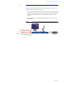
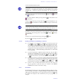
6.1.1
... without AES/EBU/ANALOGUE module
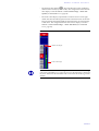
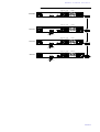
FIG. 13
On Air mixing signal of all
selected caller
Pre Talk output
DEFAULT OPERATION WITHOUT AES/EBU/ANALOGUE MODULE
presenter/music
Pre Talk output
Without the AES/EBU/Analogue module (see Fig. 13) at least two systems are
necessary, to ensure that two Audio interfaces are available. Additionally, up
to four ISDN S0 lines for 8 callers are available.
By installing further MAGIC ISDN Telephone Hybrid Slave systems as well as
AES/EBU/Analogue Modules, the system can be upgraded according to requirements.
6.1.2
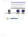
... with the AES/EBU/ANALOGUE module
When using the AES/EBU/Analogue Module (see Fig. 14) one system is enough
for the Pre Talk and On Air functionality with two ISDN S0 lines for four callers. The free Audio interface can be used, e.g. for a separate Hold signal.
By installing further MAGIC ISDN Telephone Hybrid Slave system(s) as well as
AES/EBU/Analogue Modules, the system can be upgraded according to re-
PAGE 35
O p e r a t i n g
M o d e s
quirements.
FIG. 14
On Air mixing signal of all
selected callers
Pre Talk output
PAGE 36
presenter/music
Pre Talk input
DEFAULT OPERATION WITH AES/EBU/ANALOGUE MODULE
O p e r a t i n g
6.2
M o d e s
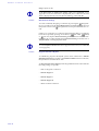
Multi fader operation with AES/EBU/Analogue module
In this operating mode the callers are not mixed in the system, they are released separately on different Audio lines:
– Usage of at least two alternative On Air Audio interfaces and one Pre Talk
Audios interface. Depending on the system build, a maximum of four separate alternative On Air lines can be installed (see CHAPTER 7.7.3.1.2,
page 60).
– The Pre Talk can be done via the Pre Talk Audio interface or via the optional handset.
FIG. 15
MULTI FADER OPERATION WITH AES/EBU/ANALOGUE MODULE
On Air 1
presenter/music 1
On Air 2
moderator/music 2
Pre Talk output
Pre Talk input
PAGE 37
O p e r a t i n g
M o d e s
6.3
Multi-Pre-Talk with AES/EBU/Analogue module
In this operating mode, a screener place is connected in parallel to the studio
via another alternative Pre Talk Audio interface. The Pre Talk of the presenter
and the Pre Talk of the screener can be used independently. Depending on the
system construction, up to six alternative Pre Talk lines are possible.
The screener can talk to the callers via a normal telephone and with the help
of the call forwarding function.
FIG. 16
PAGE 38
MULTI-PRE-TALK WITH AES/EBU/ANALOGUE MODULE
M A G I C
7
MAGIC
TOUCH
T O U C H
S o f t w a r e
SOFTWARE
The configuration of the system is done by the Windows PC software MAGIC
TOUCH, included in the delivery.
7.1
Hardware requirements
The PC must have the following minimum requirements:
– IBM PC AT, IBM PS/2 or 100% compatible
– Pentium Processor (> 266 MHz) recommended
– Windows 95B/98/ME/2000/XP operating systems
– 5 MB available hard disk space
– screen resolution of 1024 x 768 or restricted to 800 x 600 pixels (max. 5 caller
lines)
– at least one available RS232 serial interface
– Microsoft, IBM PS/2 or 100% software compatible mouse
7.2
Installation of the Windows PC Software MAGIC TOUCH
Insert the included disk in the disk drive and press the START button on Windows 95B/98/ME/2000/XP. Select the sub menu item Run... and insert into
the command line
<drive name:>setup.exe
(e.g. A:setup.exe).
Follow the installation program instructions.
After the installation start the software , by clicking the MAGIC TOUCH
symbol.
Connect the PC via a null modem cable (pin 2 and pin 3 are crossed, pin
5=GND) to the system.
Turn the system on.
The red blinking ALARM LED signals that the system is booting. After approx. 45 seconds the LED stops blinking. The system is now ready for operation.
PAGE 39
M A G I C
T O U C H
S o f t w a r e
L
PAGE 40
The de-installation software is started by clicking the uninstall symbol.
M A G I C
7.3
T O U C H
S o f t w a r e
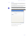
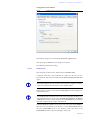
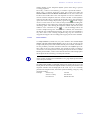
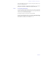
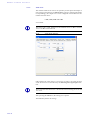
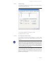
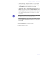
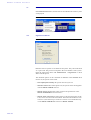
Configuration of the COM-Port
To configure the system, first the serial connection between PC and system
has first to be established.
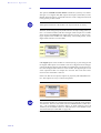
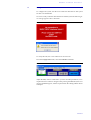
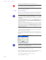
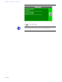
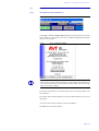
In case of a faulty connection between the PC and the system the following error message appears after a short time:
FIG. 17
ERROR MESSAGE WHEN COMMUNICATION IS INTERRUPTED
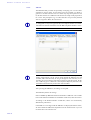
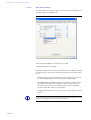
To rectify the fault, the correct interface has to be chosen.
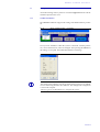
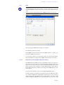
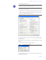
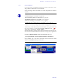
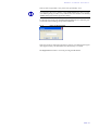
From the Configuration menu, select the COM Port submenu.
FIG. 18
CONFIGURATION MENU → COM PORT
Adjust the Port, which is connected to your PC. All other parameters, for example baud rates cannot be changed. After pressing the OK button, the error
message should disappear, otherwise please check the cabling and the chosen
COM port.
PAGE 41
M A G I C
T O U C H
S o f t w a r e
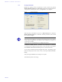
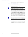
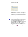
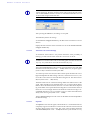
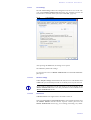
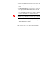
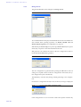
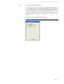
FIG. 19
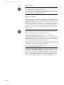
L
COM PORT
Windows NT4.0/2000/XP
When using Windows NT/2000/XP, the setting of the COM port can only be
done by an administrator. Settings can be changed but they will not be accepted.
For configuration always log in as an administrator.
PAGE 42
M A G I C
7.4
T O U C H
S o f t w a r e
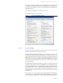
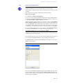
Quick installation
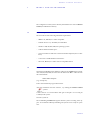
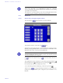
For a quick installation the most important settings will now be described.
Make sure that the system is turned on and that at least the PC is connected
to the system via the RS232 null modem cable. For the first test, the ISDN lines
should also be connected.
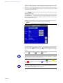
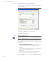
(1)
Open the system configuration via Configuration → System → Edit and go to
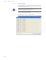
the link Slave Search. Then press the Auto detect button. After a short time all
Slave systems will be displayed.
For details see CHAPTER 7.7.3.2, page 69.
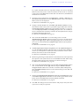
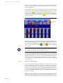
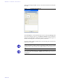
(2)
Change to the link S0 Line. Set via Number of B channels visible how many
lines shall be visible. If the system is operated through a PABX enter in the 1st.
external Prefix Number submenu the prefix number (normally "0"). In most
cases the Skip Prefix Number on incoming call option has to be set additionally. If a telephone that transmits its number calls the Hybrid System, the prefix number must not be displayed.
For details see CHAPTER 7.7.3.4, page 73.
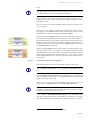
(3)
Click on the link Audio Lines. For each existing system, set in the
AES/EBU/Analogue Module submenu whether you want to use either the analogue or the digital input. When using digital inputs, the clock source has
also to be set in the Clock source of digital output submenu (mostly Recovered Clock).
For details see CHAPTER 7.7.3.14, page 98.
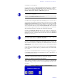
(4)
In Audio input/output interface assignment, press the Default Settings button. The Pre Talk and On Air Audio interfaces are preselected as default. Of
course if you already know which Audio interfaces shall be used for which
function, the selection can be made manually.
For details see CHAPTER 7.7.3.14, page 98.
(5)
When using the analogue Audio interfaces the nominal level for the input and
the output for each system must be set via the Audio Level link. When using
the digital Audio interfaces the nominal level cannot be changed.
For details see CHAPTER 7.7.3.9, page 86.
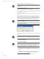
(6)
Click on the link Signal Processing. Press Set AGC on/off for all lines and the
AGC is turned off for all lines (off). Afterwards press Set Echo Canceller
on/off for all lines and the echo canceller is turned on (ON). Subsequently,
press the Default Settings button to set the default settings for the AGC and
the Expander.
For details see CHAPTER 7.7.3.11, page 89.
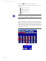
(7)
Switch to the Hold Signal Recording/Source link. Select the Hold signal source
in the HOLD Signal Source submenu. Now the Audio signal which is heard
by the callers in the Hold mode (normally On Air) is defined.
For details see CHAPTER 7.7.3.10, page 87.
(8)
Press OK. The settings will be stored on the PC and partly in the system. The
system is now ready for operation.
PAGE 43
M A G I C
T O U C H
S o f t w a r e
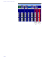
7.5
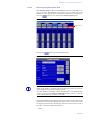
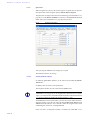
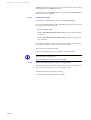
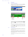
Operating elements of the MAGIC TOUCH Software
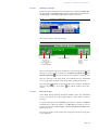
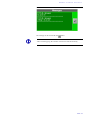
After starting the software, the main panel of the MAGIC TOUCH application
appears. Depending on the configuration, two different screen contents are
displayed:
– only one detailed information field for all callers is displayed
– each caller has his own information field
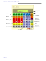
The main user elements are shown in Fig. 20.
For the following screenshots, the second possibility was used.
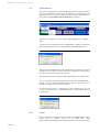
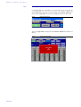
FIG. 20
MAIN PANEL OF THE MAGIC TOUCH SOFTWARE
operation keys
name and telephone number (City) of the selected caller
six
quick dial keys
editing of the caller data
lock
system
drop
all
connections
manual
dialling
select
call forwarding
destination
menu bar
pre talk source selection
operation keys
name and telephone number (location) of the caller
editing of the caller data
preselection of a line
info field about the caller
caller in Pre Talk
caller in the ’Hold’ mode
caller in the ’On Air’ mode
drop connection
forward caller
caller lines
level meter
PAGE 44
level control
M A G I C
7.5.1
Operation keys
7.5.1.1
PRE TALK SRC (Pre Talk Source)
T O U C H
S o f t w a r e
With the help of the PRE TALK SRC button it can be selected whether the Pre
Talk should be done via the optional handset (
key setting) or via the
Audio input which is configured as Pre Talk (
key setting) (see
CHAPTER 7.7.3.14, page 98).
L
The switch over of the Pre Talk Source can also be automated. In this case for
example, the presenter must always use the Audio input and the Pre Talk
source must always use the Handset (configuration in the LAN → Restrictions → Pre Talk Source Auto Following submenu (see CHAPTER 7.7.3.13,
page 95))
The Pre Talk mode is automatically signalled by the Pre Talk Relay (see
CHAPTER A4.5, page 146).
L
7.5.1.2
If the presenter switches the caller into Pre Talk the Pre Talk Relay can be
used to switch in a mixer automatically. If the Pre Talk Source is automated
(see previous info box) the Pre Talk Relay will also switch in the mixer only
if the pre talk source is in pre talk with the caller. In the General → Pre Talk
relay submenu choose the Pre Talk Signalling combined with Pre Talk
Source option to switch in the mixer only if the presenter is in pre talk via the
Audio input. Do not forget to set in the Relay submenu (see CHAPTER
7.7.3.15, page 102) the Audio Line → PRE TALK assignment for at least one
relay to ensure that a Pre Talk relay exists.
GLOBAL (Drop All, Lock)
With the help of the
(drop all connections) operating key all connections are dropped. Not included in this function are lines defined as VIP lines
(see CHAPTER 7.7.3.5, page 76).
If the
(Lock) button is active (
key setting), all lines of the system are blocked for incoming calls. Lines defined as VIP lines are excepted
(see CHAPTER 7.7.3.5, page 76). Outgoing calls are possible on any line.
L
7.5.1.3
If the lock button is active, the callers hear the busy signal. This function depends on the PABX. Main connections always support this function.
Forw. Call (Call forwarding)
The Redaktion Call Forwarding button enables the selection of two predefined
call forwarding destinations. The second call forwarding destination is only
for temporary use. This means that after forwarding the first call the call forwarding destination is set again.
The call forwarding destinations are defined in the submenu S0 Line → Call
Forwarding → 1st. telephone number for Call Forwarding and 2nd. telephone
number for Call Forwarding (see CHAPTER 7.7.3.4, page 73). The corresponding Name of the call forwarding is displayed on the operating key.
PAGE 45
M A G I C
T O U C H
S o f t w a r e
L
If no telephone number is entered, either the manual dial panel or the telephone book (depending on the Miscellaneous settings (see CHAPTER
7.7.3.1.8, page 68)) will be opened. Therefore the temporary call forwarding
is possible to any destination.
This function is a good possibility for the call forwarding destination. Enter
for example ’Manual’ as Name to keep the function in mind.
7.5.1.4
Manual Call
7.5.1.4.1
Manual call by entering the telephone number
The operating key
FIG. 21
opens the dialog for manual dialling.
DIALOG FOR MANUAL CALL
The telephone number is entered by the
...
keys.
Alternatively, the keypad of the PC can also be used. The connection is established by pressing the Enter button . If the connection is established via the
Enter button the caller is always put in the Hold mode.
L
In the case that the Telephone Hybrid system is operated through a PABX,
the prefix number (the number is usually "0") has to be entered for external
calls (see CHAPTER 7.7.3.4.3, page 75).
Key
deletes the complete entry, key
the entry.
deletes only the last character of
The establishment of the connections is activated by pressing either the
(Pre Talk) button, the
(Hold) button or by pressing the
(On Air) button. Automatically, the next available line is used.
To close the dialog without establishing a connection, press key
.
These six keys
are programmable quick dial keys. They can be programmed via the Quick Dial system configuration (see CHAPTER 7.7.3.8,
page 84).
PAGE 46
M A G I C
7.5.1.4.2
T O U C H
S o f t w a r e
Manual call using the telephone book
If the Database Support option in the Database menu (see CHAPTER 7.7.3.3,
page 70) is active, the telephone book function is also available next to the
manual call. The telephone book is designed as a database for the whole system. The
button is now visible in the MAGIC TOUCH panel.
FIG. 22
MAGIC TOUCH WITH TELEPHONE BOOK
telephone book
Pressing the
FIG. 23
L
button opens the telephone book.
TELEPHONE BOOK
Windows NT4.0/2000/XP
When using Windows NT/2000/XP, the essential files for the use of the database support are part of the operating system.
All other Windows operating systems need the MS® Access 2000 database
software or the optional MAGIC SCREENER database software, which includes a Runtime Version of MS® Access 2000.
In the Search Name field the desired name can be entered. The names in the
telephone book are listed in alphabetical surname order. All relevant entries
are displayed automatically. By clicking a name the respective data record of
the caller is shown. Available information is:
– Name
PAGE 47
M A G I C
T O U C H
S o f t w a r e
– First Name
– City
– Number
– Gender (male, female or unknown)
– VIP (Very Important Person)
– Lock (allowed to call in = caller is not blocked or not allowed to call in =
caller is blocked)
– Last Call
– Information/Topic
The establishment of the connection of the currently selected caller is made by
pressing the buttons
Pre Talk,
Hold or
On Air. The next available
line is chosen automatically.
To close the dialog without connection, press the
By pressing the
With
record.
button.
(NEW) button, a new caller can be entered.
(EDIT) it is possible to change the currently displayed data
The
(DELETE) key cancels the currently displayed data record. Be
careful, there will be no pre-confirmation whether the data record is definitely
to be deleted!
The
(EXTERN 2 = 2nd prefix number) key is only displayed if a 2nd.
prefix number was entered in S0 Line → Prefix Numbers. The Name displayed
on the button can be changed.
After pressing the
information opens.
FIG. 24
or the
button, the dialog for entering caller
DIALOG FOR ENTERING CALLER INFORMATION
Data about the caller can be entered in the Name, First Name, City and Information fields.
The telephone number can only be entered in the Number field if the number
PAGE 48
M A G I C
T O U C H
S o f t w a r e
was not transmitted by the system.
L
If the Telephone Hybrid is operated via a PABX, the Prefix Numbers (see
CHAPTER 7.7.3.4.3, page 75) for internal calls can be suppressed via a minus
character (’-’). To suppress the number the prefix number has to be entered
including the ’-’ prefix (for example: If the number 130, ’-130’ must be entered).
The gender of the caller can be defined using the
and
(male) button .
A caller can be defined as VIP by pressing either the
(VIP) button.
(unknown),
(female)
(no VIP) button or the
A caller can be blocked by pressing either the
(not blocked) button or by
pressing the
(blocked) button. The duration of the lockage is automatically
set for 1 year.
L
With the help of the MAGIC SCREENER database software, blocked callers
can easily be managed. On one side different blocking periods can be set and
on the other side, this blocking period is automatically checked. Therefore after the expiration of the blocking period the lockage is deleted.
In addition to the entry of Information or of the topic, the mood of the caller
can be entered. The following entries are possible:
(friendly),
(neutral),
(unfriendly).
All entries are accepted and stored by pressing the
By pressing
7.5.1.4.3
7.5.1.5
button.
all changes and entries are deleted.
Further possibilities for establishing a connection
(1)
If you want to call a person on a certain line, you must only press one
of the
(Pre Talk),
(Hold) or
(On Air) buttons of an available line in the MAGIC TOUCH main panel. Depending on the configuration, either the manual call dialog or the telephone book opens. The
configuration of this optional function is made with General → Miscellaneous Settings → Show dial dialog on disconnect (see CHAPTER
7.7.3.1, page 58).
(2)
If one line is defined as a VIP line and if for this line, only one VIP is
selected (see CHAPTER 7.7.3.5, page 76), the connection to this VIP is
automatically established when either the
(Pre Talk),
(Hold)
or
(On Air) button is pressed in the MAGIC TOUCH main panel.
(3)
If one line is preset for a call (name is displayed in the information field
even if there is no connection), the connection to the preset caller can be
established by pressing either the
(Pre Talk),
(Hold) or
(On Air) button of the line in the MAGIC TOUCH main panel
(4)
If there is only one defined information field for all caller lines (see
Fig. 20, page 44) six quick dial keys are available in the MAGIC
TOUCH main window for the direct calling.
Information
The detailed information area is only available if the display setting is configured accordingly. In General → Display Settings the Information for each
caller option (see CHAPTER 7.7.3.1.6, page 66) must not be set. The
(Edit)
key enables the displayed caller information (see Fig. 24, page 48) to be
changed.
PAGE 49
M A G I C
T O U C H
S o f t w a r e
The display of the caller information in this presentation can be automated via
General → Display Settings → Show Information automatically (see CHAPTER 7.7.3.1.6, page 66). If this option is set, the information on the caller whose
mode has just been changed is displayed (e.g. when switching from Pre Talk
to Hold) is always displayed.
Via the
(Info) button the information of each connected caller can be
displayed at any time.
Also the display of the name and the telephone number is done with the help
of the Info button. To display the name, it must have been previously entered
into the telephone book database and the telephone number has to be transmitted from the caller’s end.
If there is no connection on a line, the line can be predefined for a call. Pressing
(Info) opens the extended telephone book dialog.
FIG. 25
TELEPHONE BOOK WITH LINE PREPARATION
As in the telephone book dialog a caller can be selected and be predefined for
the line using the
(SET) button. The
(CLEAR) key deletes all presettings. After selecting the caller the name of the caller is displayed in the Info
button.
The establishment of the connection is done by pressing one of the following
buttons
(Pre Talk),
(Hold) or
(On Air).
L
The system tries to keep the predefined lines for incoming calls available as
long as possible. These lines will be used only when no other line is available.
The presettings will not be deleted however.
Additionally, beneath the info button, the temper
tral),
(unfriendly), age and gender
(male),
are displayed.
L
PAGE 50
(friendly),
(neu(female) of the caller
The entry and the indication of the age is only possible with help of the optional MAGIC SCREENER database software.
M A G I C
7.5.2
T O U C H
S o f t w a r e
Line functions
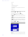
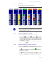
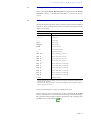
The following figure shows the possible line modes:
FIG. 26
No
Connection
Predefined
call
L
7.5.2.1
Incoming call
(blinking)
LINE FUNCTIONS AND MODE DISPLAY
Caller in
Pre Talk
Caller in Hold
position
Caller
On Air
Caller being forwarded
Depending on the usage of the MAGIC TOUCH LAN or MAGIC SCREENER
software options, single lines can be highlighted in grey. Then the MAGIC
TOUCH user has no further access anymore to this line. Transfer point is always the Hold mode. It sets a line free.
Line functions without existing connection
If there is no connection the following functions are available:
– By pressing the
(Pre Talk), the
(Hold) or the
(On Air) button, either the manual call dialog or the telephone book opens depending
on the configuration. The configuration of this optional function is done
via General → Miscellaneous Settings → Show dial dialog on disconnect
(see CHAPTER 7.7.3.1, page 58).
– With the help of the
information button, a line can be predefined
for a call (see Fig. 25, page 50)
7.5.2.2
Line functions with existing connection or incoming call
If there is an existing connection or an incoming call the following functions
are available:
– The
(Pre Talk) key switches the caller in pre talk . This key is only
available if a Pre Talk Audio interface was defined in Audio Lines (see
CHAPTER 7.7.3.14, page 98).
– The
(Hold) key puts the caller in the hold position
. Now the caller
hears the selected signal, defined in Hold Signal Recording/Source → General Settings → Hold Signal Source (see CHAPTER 7.7.3.10, page 87).
PAGE 51
M A G I C
T O U C H
S o f t w a r e
– The
(On Air) key switches the caller on air
. The key is only available
if an On Air Audio interface was defined in Audio Lines (see CHAPTER
7.7.3.14, page 98).
– The
(Drop) key drops the connection.
To avoid accidentally dropping of a connection, the Drop function can be
configured in the General Settings → Miscellaneous Settings → Press
DROP button 1 second to hang up submenu (see CHAPTER 7.7.3.1,
page 58). Accordingly, the button must be pressed for 1 second before the
connection is dropped.
– The
(= Call Forwarding) key forwards the caller to one of the call forwarding targets (see CHAPTER 7.5.1.3, page 45).
If the caller has already been forwarded, he can be recalled by pressing
.
Then the caller is automatically again in the Hold position and is available
for all functions. The call forwarding function is only available if it has
been activated in S0 Line → Call Forwarding → Enable Call Forwarding
(see CHAPTER 7.7.3.4, page 73).
– If the display with only one caller information field is chosen the
(Info) key updates the field. If the display with an information field for
each caller is chosen, the information button opens the dialog for entering
the caller information (see CHAPTER Fig. 24, page 48).
Via the Info button, the caller’s name and telephone number are displayed.
It is assumed that the caller has already been entered into the Telephone
Book Database and the telephone number has been transmitted from the
caller’s end.
L
7.5.2.3
Via the optional MAGIC SCREENER database software, the location of the
caller can be displayed instead of the telephone number. The configuration is
made in the General → Display Settings → Display City instead of telephone
number submenu (see CHAPTER 7.7.3.1.6, page 66).
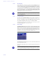
Level Meter Display
The level meter display (see Fig. 20, page 44) shows the Audio level of the
caller between the range of -36 ... +12dBr. The resulting absolute level adjusts
the level setting in Audio Level → Master and Slave. For example: incoming
level = -15dBr, set Audio Level Out = +6dBu. At this moment it sets an absolute output level of -9dBu. The headroom in the system is always 6dB.
7.5.2.4
Level setting
The Audio signal of the caller can be reduced or increased between the range
of -16dB... +16dB. The level setting (see Fig. 20, page 44) can, during an existing connection, either be dragged to the desired position or it can be put to
the desired position by clicking. After dropping the connection the level setting is set back to 0dB.
L
7.5.2.5
The level adjustment can only be used if the AGC (Automatic Gain Control)
for this line has been turned off (see CHAPTER 7.7.3.11, page 89).
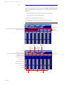
Time information
There are two optional timer available to indicate how long a caller has been
in the connection mode:
PAGE 52
M A G I C
T O U C H
S o f t w a r e
– The absolute time display
, shows the duration of the condition in
minutes and seconds (or just in seconds). The configuration of the absolute
time display is done in General → Time related settings → Show time
symbol (see CHAPTER 7.7.3.1, page 58).
– The relative time display represented as a time bar shows at first sight,
which caller has been the longest time in the connection mode. If one time
beam reaches the maximum height all other time beams are automatically
scaled down. The configuration of the relative time display is made in
General → Time related settings → Show Time Beam (see CHAPTER
7.7.3.1, page 58).
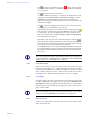
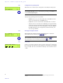
FIG. 27
ABSOLUTE AND RELATIVE TIME DISPLAY
absolute time display
relative time display
L
If the General → Time related settings → Reset time on Audio Line change
option (see CHAPTER 7.7.3.1, page 58) is not set, the time beam is displayed
in yellow. Otherwise the time beam is the colour of the line mode (e.g. red for
On Air)
PAGE 53
M A G I C
T O U C H
S o f t w a r e
7.6
Menu File → Exit
Selecting the File → Exit menu completes the application.
PAGE 54
M A G I C
7.7
T O U C H
S o f t w a r e
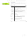
Configuration Menu
All essential settings of the systems are set in the Configuration menu. The detailed description follows now.
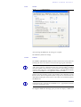
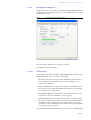
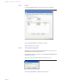
7.7.1
COM Port Submenu
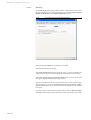
The COM Port submenu supports the setting of the RS232 interface parameter.
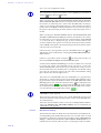
FIG. 28
MENU CONFIGURATION → COM PORT
Set on your PC the Port to which the system is connected. All other parameters, such as the baud rate, cannot be changed. After pressing the OK button,
the settings are accepted. The Cancel button deletes all settings.
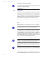
FIG. 29
L
COM PORT
Windows NT4.0/2000/XP User
The setting of the COM port can only be made when logged on as an Administrator when using Windows NT/2000/XP. The setting can be changed, but
it will not be accepted.
Always log on as an administrator to configure the system.
PAGE 55
M A G I C
T O U C H
S o f t w a r e
7.7.2
PC Keypad Submenu
Besides the operation with a touchscreen or with a mouse, the optional
MAGIC Hybrid Keypad PC (see CHAPTER 8, page 125) can also be used. The
configuration of the keypad is done in Configuration → PC Keypad.
FIG. 30
KEYPAD SETTINGS
With this panel, set the Port on your PC via RS232 Parameter, to which the
MAGIC Hybrid Keypad PC is connected. All other parameters such as baud
rate cannot be changed.
L
Windows NT4.0/2000/XP User
The setting of the COM port can only be made when logged on as an administrator when using Windows NT/2000/XP. The setting can be changed, but
it will not be accepted.
Always lon on as an administrator to configure the system.
Via Remote available Presets, a maximum of five Presets (see CHAPTER
7.7.4, page 107) are displayed. These presets can be selected via the keypad.
Set the Enable remote Preset selection option to activate the function.
To get a better orientation between keypad and screen, a numbering of the
lines can be displayed on the screen. For this, set the option Show Line Numbering.
After pressing the OK button all settings are accepted.
The Cancel key deletes all settings.
PAGE 56
M A G I C
FIG. 31
T O U C H
S o f t w a r e
MAGIC TOUCH DISPLAY WITH LINE NUMBERING
PAGE 57
M A G I C
T O U C H
S o f t w a r e
7.7.3
System Submenu
The system configuration is arranged on different links according to functionality. For most functions at least two Audio interfaces are assumed (e.g. Pre
Talk and On Air). For special possibilities or when using the digital Audio inputs/outputs the AES/EBU/ANALOGUE Module is required.
FIG. 32
MENU CONFIGURATION → SYSTEM
The current configuration can be edited with Configuration → System →
Edit.
To generate a new configuration select Configuration → System → New. New
names can be entered for a new configuration in the Preset Name panel.
FIG. 33
PRESET NAME PANEL
After pressing the OK button the new configuration is generated. All current
settings are now accepted as a basis for the new configuration. Subsequently,
the system configuration opens automatically.
The Cancel button closes the panel without generating a new configuration.
To store an existing configuration under a new name select Configuration →
System → Save As. The Preset Name panel also displays. The new name for
the current configuration can now be entered.
If a name already exists for a configuration a note is displayed. In case you
want to overwrite the name, confirm the question by answering Yes. No cancels the input.
FIG. 34
7.7.3.1
NOTE ABOUT AN ALREADY EXISTING PRESET NAME
General
Most configuration settings are stored in Windows the Registry. The configuration can be available either for all users (key name:
HKEY_LOCAL_MACHINE) of the computer or only for the current user (key
PAGE 58
M A G I C
T O U C H
S o f t w a r e
name: HKEY_CURRENT_USER). It is recommended that one configuration is
stored for all users to keep the effort at the beginning of the operation as low
as possible. The configuration can be stored with the help of the Store all settings global option.
After pressing the OK button all settings are accepted.
The Cancel key deletes all made settings.
FIG. 35
7.7.3.1.1
INDEX CARD GENERAL SETTINGS
Conference Settings
If there is more than one connection, the performance of the system can be influenced with the help of the conference settings.
The More than one person in PRE TALK option provides the possibility to talk
to all callers in the Pre Talk mode simultaneously. The signals of all callers are
digitally mixed in the system and the mixed signal is transmitted to the Pre
Talk Audio interface. Also, a digital N-1 signal is generated for each caller. If
this option is not set, only one caller can be in the Pre Talk mode. If a second
caller is put into the Pre Talk mode, the first caller is automatically switched
into the Hold mode.
The More than one person in ON AIR option enables a simultaneous On Air
conference with all callers who are in the On Air mode. The signals of all callers are digitally mixed in the system and the mixed signal is transmitted to the
On Air Audio interface. Also, a digital N-1 signal is generated for each caller.
If this option is not set, only one caller can be in the On Air mode. If a second
caller is put in the On Air mode the first caller is automatically switched into
the Hold mode.
To ensure that one or several callers can be in the Pre Talk mode as well as in
the On Air mode, the PRE TALK and ON AIR concurrently option must be
active. If this function is not active, several callers can either be in Pre Talk or
PAGE 59
M A G I C
T O U C H
S o f t w a r e
be On Air. If for example, three callers are in the Pre Talk mode and one of
them is switched into the On Air mode, then the other two are automatically
put into the Hold mode.
The Next-Mode was especially implemented for game shows. This provides
the possibility of putting the callers on Hold immediately without a Pre Talk.
By pressing the
(Next) button on the MAGIC TOUCH user interface
the caller who has been waiting the longest time in the system is automatically
put On Air. By pressing the operating key
(Next) once again the next
caller is put On Air.
FIG. 36
NEXT MODE
NEXT Mode
What happens to the previous caller is defined by the After ON AIR state option. Selecting DROP drops the connection, PRE TALK puts the caller in the
Pre Talk mode and HOLD puts the caller in the Hold mode. To mark that a
caller is already On Air, the Pre Talk
and Hold
mode are highlighted
with a red font.
L
Of course, at any time each caller can be put manually in the On Air mode or
into another mode. All functions are available as usual.
If the Mix caller in HOLD to PRE TALK output option is active, the signal of
the caller in the Hold mode is mixed together with the signal of the caller in
the Pre Talk and the common signal is transmitted to the Pre Talk Audio interface. This function is quite useful for recognising that a caller wants to say
something but no extra Hold Audio interface was defined (see CHAPTER
7.7.3.14, page 98).
7.7.3.1.2
Alternative Audio Line Mode
So far, only the Pre Talk, perhaps the Hold and the On Air Audio interfaces
were used. Additionally all callers On Air or in the Pre Talk mode were automatically mixed in the system. If it is desired to put several callers On Air or
to use several Pre Talk Audio interfaces - without mixing them- the alternative Audio Line Mode can be used. Depending on the construction of the system up to four alternative On Air and up to six alternative Pre Talk Audio
interfaces are possible.
The release of this operating mode is done by the Enable Configuration of Alt.
Audio Lines option. Therefore, at first, there are four alternative Lines available for On Air and Pre Talk for the configuration of the Audio interfaces (see
PAGE 60
M A G I C
T O U C H
S o f t w a r e
CHAPTER 7.7.3.14, page 98).
To select and activate configured alternative On Air Lines on the MAGIC
TOUCH user interface the Activate Mode option has additionally to be set.
The activation of alternative Pre Talk Audio interfaces can only be done via
MAGIC TOUCH LAN or MAGIC SCREENER applications.
L
Keep in mind that the Pre Talk, Hold and On Air Audio interfaces can still be
used if they are configured.
Therefore the maximum build provides a total of twelve 1 different Audio interfaces for the MAGIC TOUCH user interfaces.
1
Until release 3.0 a maximum of only seven Audio interfaces are available.
If the Reset Line to Default Audio Line on DROP option is active the line is
automatically switched to the default On Air Audio interface after the establishement of the connection. This does not depend on the selection of the alternative On Air Line. The standard Audio interface is the On Air Audio interface, if defined. Otherwise it is the defined alternative On Air Line with the
smallest index (e.g. Alternative On Air Line 1).If the option is not set, the setting of the Audio interface is kept after the connection is dropped.
Normally, the alternative On Air Lines are only used if no conference between callers is desired. However, if several lines with the same alternative
On Air Line are used, a conference between the callers of the same alternative
On Air Line can be set up.
L
This function also effects the alternative Pre Talk Lines, which can be used
by MAGIC TOUCH LAN or by MAGIC SCREENER.
For this set the Alternative Audio Lines concurrently option. Therefore with
the maximum construction one On Air, four Alternative On Air and one Pre
Talk conference can be implemented simultaneously on the MAGIC TOUCH
user interface.
If this option is not used always only one caller can be on the alternative Line.
Callers who have the same index (e.g. alternative Line 1) are automatically
put on Hold.
The selection of the alternative Line in use is done by a long pressing (approx.
1-2 seconds) of one of the keys Pre Talk, Hold or On Air or Alternative 1...4
on the MAGIC Touch surface.
L
If there is an existing connection, only the button with the active mode can be
pressed to avoid an accidental switch over (see Fig. 38, page 62).
If there is no connection, any button can be pressed.
When operating with the mouse press the left mouse button. The Preselect the
Audio Line dialog for the preselection of the alternative On Air Audio interface opens.
FIG. 37
DIALOG TO PRESELECT THE ON AIR AUDIO INTERFACE
PAGE 61
M A G I C
T O U C H
S o f t w a r e
By pressing the
button the dialog closes without change.
The selection of the desired Audio interface is done by pressing one of the following keys
L
–
(Alternative On Air Line 1)
–
(Alternative On Air Line 2)
–
(Alternative On Air Line 3)
–
(Alternative On Air Line 4)
–
(On Air).
This dialog shows only the keys which were defined when configuring the
Audio interfaces (see CHAPTER 7.7.3.14, page 98).
The alternative On Air Line can be selected any time, even during an existing
connection.
See Fig. 38 as an example for the use of alternative lines. During the show, two
players are playing against each other. They operate the computer game via
DTMF tones. To allocate the tones very clearly, both callers are put on separate Audio interfaces. Lines 3 and 4 are already prepared as alternatives to
Lines 1 and 2. If a further caller on Line 3 is switched to the alternative Line 1
a conference between line 1 and line 3 would be possible (if Alternative Lines
concurrently option has been set).
FIG. 38
ACTIVATION FOR SELECTING ALTERNATIVE LINES
Long pressing opens
the dialog to preselect the
Audio interface
PAGE 62
M A G I C
7.7.3.1.3
T O U C H
S o f t w a r e
Replace Mode
The Replace Mode option was integrated especially for the operation of the
Telephone Hybrid system as a command device. For example (see Fig. 39) the
high quality image and high quality sound are transmitted via satellite to the
studio. The command line is provided to the correspondent via a normal telephone.
FIG. 39
APPLICATION FOR THE REPLACE MODE
To use the advantages of the Hybrid system the incoming signal of the satellite is fed by the correspondent via an Audio interface, to the Hybrid (Replaced x). Via the Telephone Hybrid a default connection is established to the
correspondent. Now the system replaces the telephone back channel via the
Replaced line. The command line (channel to the telephone) will not be
changed. It is now possible to have any conference in the studio with several
correspondents. Several alternative Lines, as well as the Hold and On Air
Lines, can be defined as Audio interfaces to the mixer.
All functions of the Hybrid are available. A correspondent can even be transfered to an optional telephone.
L
In total a maximum of 12 Replaced Lines and Hold/On Air/Alternative Lines
is possible since the system provides within the complete build, a total of
twelve 1 Audio interfaces. A Pre Talk Audio interface can not be defined because it does not make any sense considering the operating technique.
1
Until release 3.0 a maximum of only seven Audio interfaces are available.
If the Replace Mode → Enable configuration of Replaced B channels option is
active the Audio interfaces in Audio Lines → Audio Input/Output Interface
Assignment (see CHAPTER 7.7.3.14.2, page 99) can be defined as Replace B
channel Line 1...12. This option defines which line (B channel) is replaced by
which Audio interface. For a better identification the associated Input is indicated in the index.
Additionally, the MAGIC TOUCH user interface displays a symbol on the
particular line (e.g.
for input 1) with the relevant Audio input interface
(see Fig. 40).
PAGE 63
M A G I C
T O U C H
S o f t w a r e
FIG. 40
DISPLAY OF THE AUDIO INPUT INTERFACE ON THE USER INTERFACE
selected Audio
input interface
The numbering of the interfaces of the Hybrid system is assigned as follows:
Input
PAGE 64
System Audio Interface
1
Master: Analogue Audio (Standard Audio interface)
2
Master: AES/EBU/ANALOGUE Module left
3
Master: AES/EBU/ANALOGUE Module right
4
Slave 1: Analogue Audio (Standard Audio interface)
5
Slave 1: AES/EBU/ANALOGUE Module left
6
Slave 1: AES/EBU/ANALOGUE Module right
7
Slave 2: Analogue Audio (Standard Audio interface)
8
Slave 2: AES/EBU/ANALOGUE Module left
9
Slave 2: AES/EBU/ANALOGUE Module right
10
Slave 3: Analogue Audio (Default Audio interface)
11
Slave 3: AES/EBU/ANALOGUE Module left
12
Slave 3: AES/EBU/ANALOGUE Module right
M A G I C
FIG. 41
Audio 2 (L), 3 (R)
0 I
S o f t w a r e
SYSTEM AND AUDIO INTERFACE ASSIGNMENT
POWER 115/230V
MASTER
T O U C H
USER I/O
RS232C
AES/EBU
ANALOGUE
LSD
HSD
Audio 1
1
So
2
EXTENSION BUS
OUTPUT CMD INPUT
Audio 5 (L), 6 (R)
POWER 115/230V
SLAVE 1
0 I
USER I/O
RS232C
AES/EBU
ANALOGUE
LSD
HSD
Audio 4
1
So
2
EXTENSION BUS
OUTPUT CMD INPUT
Dongle: Slave 1
Audio 8 (L), 9 (R)
POWER 115/230V
SLAVE 2
0 I
USER I/O
RS232C
AES/EBU
ANALOGUE
LSD
HSD
Audio 7
1
So
2
EXTENSION BUS
OUTPUT CMD INPUT
Dongle: Slave 2
Audio 11 (L), 12 (R)
POWER 115/230V
SLAVE 3
0 I
USER I/O
RS232C
AES/EBU
ANALOGUE
LSD
HSD
Audio 10
1
So
2
EXTENSION BUS
OUTPUT CMD INPUT
Dongle: Slave 3
PAGE 65
M A G I C
T O U C H
S o f t w a r e
7.7.3.1.4
PRE TALK Relay
The Pre Talk mode is automatically signalled via the Pre Talk Relay and can
be used to switch a mixer automatically if the programme presenter switches
a caller into Pre Talk. When automating the Pre Talk Source (see CHAPTER
7.7.3.13, page 95) the Pre Talk Relay will also switch the mixer, even though
only the pre talk source is in Pre Talk via the handset with the caller. With the
help of the Pre Talk Relay → Pre Talk Signalling combined with Pre Talk
Source option the switchover of the mixer is only made if the presenter uses
the Pre Talk Audio interface and not the handset.
L
7.7.3.1.5
Do not forget to set the Audio Line → PRE TALK assignment, in the Relay
submenu (see CHAPTER 7.7.3.15, page 102) at least for one relay, to ensure
that a Pre Talk Relay exists.
Level Meter Settings
The setting of the Level Meter Setting (see Fig. 20) enables to adjust the update interval of the display if PCs with a lower performance are used. If very
slow PCs (< 100 MHz) are used, select Seldom; when using PCs between
100...300 MHz set Moderate and for faster PCs > 300 MHz set Often.
The Flicker Free Drawing of the Level Meter option must only be set, if the
Level Meter Setting flickers a lot on your screen.
7.7.3.1.6
Display Settings
The MAGIC TOUCH user interface permits two different presentations: If the
Information for each caller option is not active, only one detailed information
field for all callers (see Fig. 42) is displayed. In this kind of presentation, the
display can be automised if the Show Information automatically option is
set. Therefore, always, the information on the caller whose mode has been
changed (e.g. when switching from Pre Talk to Hold) is shown.
FIG. 42
OPTION "INFORMATION FOR EACH CALLER" NOT SET
If the Information for each caller option is active, an information field for each
caller is displayed (see Fig. 43).
The Font Size setting enables the size of the the information field font to be
adjusted.
L
PAGE 66
The font size is individually stored for each setting of the number of visible B
channels (Number of B Channels visible) (see CHAPTER 7.7.3.4.1, page 73).
M A G I C
FIG. 43
T O U C H
S o f t w a r e
"INFORMATION FOR EACH CALLER" OPTION SET
If optional MAGIC SCREENER data base software is available, the location of
the caller can be displayed instead of the calling number. To do this, set the x
Display City instead of telephone number setting.
L
Note that the MAGIC SCREENER database software has to be configured accordingly.
With the help of the Default Text for Unknown Caller option, individual text
can be entered. This text is then displayed in the Info field of the MAGIC
TOUCH user interface, in the case that the number of the caller is not known
and no database entry is available.
The system allows a system configuration via Presets. Select the Show Preset
name in title bar option to display in the head bar of the application, which
Preset is currently active.
The MAGIC TOUCH user interface was especially developed for a resolution
of 1024 x 768 pixels. It is displayed at its best at a 15“ screen. For smaller
screens (e.g. 12“) with 800 x 600 pixels, the display of the MAGIC TOUCH
screen can be adjusted by activating the Use 800 x 600 resolution (max. 5 B
channels) option. When starting, the software automatically recognises the
Windows screen resolution.
L
7.7.3.1.7
With a resolution of 800 x 600 pixels a maximum of five lines can be displayed.
Time related settings
On the MAGIC TOUCH user interface, two optional timers are available:
– The absolute time display
shows the duration of the mode in minutes and seconds or only in seconds. The Show Time Symbol option activates it.
If the display of the time is in minutes and seconds and not only in seconds, the Display connection time as mm:ss option must be set.
– The relative time display in the form of a time beam shows at first sight,
which caller has been connected the longest time. If a time beam reaches
the maximum height, all other time beams automatically scaled down. The
configuration of the relative time display is done by activating Show Time
Beam (see Fig. 27).
Both time displays can be set back to zero when changing the line mode (e.g.
when switching from Hold to On Air). Select the Reset time on Audio Line
PAGE 67
M A G I C
T O U C H
S o f t w a r e
change option for this.
L
7.7.3.1.8
If the Reset time on Audio Line change option (see CHAPTER 7.7.3.1,
page 58) is not set, the time beam is displayed in yellow. Otherwise the time
beam is displayed in the colour of the line mode(e.g. red for On Air)
Miscellaneous Settings
To avoid accidentally dropping a connection by pressing the
(Drop) button, it is possible to set the Press DROP button 1 second to hang up option. If
this option is selected, the
(Drop) button has to be pressed at least for 1 second.
If there is no connection on a caller line the manual dial dialog or telephone
book can be opened by pressing one of the keys
(Pre Talk),
(Hold)
or
(On Air). Option Show Dial Dialog on disconnect activates this function. Select the according dialling dialog Manual Dialling for manual call or
Telephone Book call using telephone book.
L
7.7.3.1.9
To select Telephone Book the database support must be active (see CHAPTER
7.7.3.3, page 70).
Keypad connected to Hybrid
As redundancy purposes the Hybrid system can be connected to a MAGIC
Hybrid Keypad 4/7/12 in parallel to the MAGIC TOUCH software. Therefore,
the operation is assured if the PC fails.
Via Keypad connected to Hybrid, set the keypadthat has been connected. The
following settings are possible:
– none: no keypad is connected.
– MAGIC Keypad 4
– MAGIC Keypad 7
– MAGIC Keypad 12
– other: for future extensions.
PAGE 68
M A G I C
7.7.3.2
T O U C H
S o f t w a r e
Slave Search
If several systems are connected to each other via the Extension Bus, these systems must be installed by the software when operating for the first time. This
is done via the link Slave Search.
Press the Auto detect button to start the search. After a couple of seconds all
slave systems (maximum three) should be listed. The Master system is not
displayed. The displayed address is only relevant for internal use.
L
If one system is lacking, even though it has been connected and turned on,
check if all Dongles have been properly connected (see Fig. 11 and Fig. 12)
FIG. 44
SEARCH OF THE SYSTEMS ON THE BUS
After pressing the OK button all settings are accepted.
The Cancel key deletes the settings.
PAGE 69
M A G I C
T O U C H
S o f t w a r e
7.7.3.3
L
Database settings
Windows NT4.0/2000/XP
When using Windows NT/2000/XP all necessary files for the use of the database support are part of the operating system.
All other Windows operating systems need the database software MS® Access 2000 or the optional MAGIC SCREENER database software which contains a Runtime Version of MS® Access 2000.
Function of the database
All MAGIC TOUCH, MAGIC TOUCH LAN and MAGIC SCREENER software modules always use the same Caller.MDB database file (the so called
Back End data base) to switch caller data among callers. The file can be installed on any PC on the network. This PC as well as the index where the database file is installed, must be available via the network for all application
computers on the network. The second necessary file Screener.MDW administrates the access to the database. This file can be on the same path as well as
the database file.
L
To share a folder in the network (Windows XP)
Open the Windows Explorer and then locate the folder you want to share.
Right-click the folder, and then click sharing and security.
If the Share this folder in the network check box is available, select it.
If the Share this folder in the network check box is not available, the PC is
not connected to the network. To install a network, click on the network installation assistant link and follow the instructions to activate file sharing. As
soon as the sharing is active, start the procedure again.
To change the name of shared the folder or drive, type a new name in shared
name. The new name is what users will see when they connect to this shared
folder. The actual name of the folder does not change.
Activate the network user allowed to share files check box to permit other
users to access files in the shared folder.
The MAGIC TOUCH, MAGIC TOUCH LAN or MAGIC SCREENER application represents the Front End database. This application enables access to the
Back End. The entered path of the MAGIC TOUCH is very important to ensure that during the show, all applications work with the same Back End database file. Both, MAGIC TOUCH LAN and MAGIC SCREENER automatically receive the correct path of the currently set Back End database file.
PAGE 70
M A G I C
T O U C H
S o f t w a r e
Configuration of the database
FIG. 45
CONFIGURATION OF THE DATABASE ACCESS
The database support is activated by the Data base support option.
After pressing the OK button, the settings are accepted.
The Cancel key deletes the settings.
7.7.3.3.1
Database path
Enter the paths of the necessary database files in Database path.
If the path of the files can be indicated via a letter of a drive (e.g. S:\Program\MAGIC TOUCH\Caller.mdb) set the Allow local path for Data base
option.
L
When indicating the letter of the drive ensure that all computers of the network use the same letter of the drive for the database index.
If this option is not active, the selection of UNC path (Universal Naming Convention) must be set.
L
An UNC path can be recognised with its two prefixed „\\“. If your database
was installed in the network search for the correct path. Best possibility is to
use the Browse function and to select network environment. If the MAGIC
TOUCH user interface and the database file Caller.MDB were installed on
the same computer this procedure must be done.
In System Database (*.mdw) enter the path of the relevant Screener.MDW file.
This file can be stored in the same directory as the Caller Database that has
the name Caller.MDB in the in the delivery mode. The name of the
Caller.MDB file can be copied and changed 1 at any time.
PAGE 71
M A G I C
T O U C H
S o f t w a r e
The structure of the directory can be browsed via the Browse button.
7.7.3.3.2
MAGIC SCREENER remote control
If it is desired to use the database supported MAGIC SCREENER software in
the network, the Enabled option must be first activated.
The provided TCP/IP Port in Network settings has the default setting 8454.
Normally a change is not necessary.
L
However, if a port change, keep in mind that it is imperative that all MAGIC
SCREENER database applications have to be adjusted accordingly.
The Screening → Incoming call directly on screener telephone option must
only be active if the telephone call and the screening are realised via a separate
telephone. The caller has to call this telephone directly and for the screening,
the optional MAGIC SCREENER screening software must be in use. In this
case, the caller data can be entered into the database as usual. If the caller is to
be screened, the SCREEN button of the MAGIC SCREENER software must be
pressed. Thereby the caller’s information is transmitted to the MAGIC
TOUCH software. Afterwards, the screened caller is forwarded to the Hybrid
system by a normal call forwarding of the screener telephone. The Hybrid
system recognises by the call forwarding number (that means that the
screener telephone must transmit its own telephone number) the screened
data record and displays it on the screen. More information can be found in
the MAGIC SCREENER documentation.
L
7.7.3.3.3
Do not mistake this option not with Pre Talk via call forwarding (see CHAPTER 7.7.3.4.2, page 74). For that function the caller can call the Telephone Hybrid directly and is then transmitted through the system to a normal telephone for the Pre Talk. During this action the caller is kept within the Hybrid
system.
Miscellaneous
With the help of the Miscellaneous Settings → Automatically clearing of Information on incoming call option, you can select if the info field will either
be deleted (active) automatically if a caller calls again or if the field will be
kept (non active).
1The
PAGE 72
file Screener.MDW must not be named.
M A G I C
7.7.3.4
T O U C H
S o f t w a r e
S0 Line
FIG. 46
S0-LINE SETTINGS
After pressing the OK button, all settings are accepted.
The Cancel key deletes all settings.
7.7.3.4.1
General
The Number of B Channels visible parameter indicates how many lines will
be displayed on the user interface. The allowed range is given in brackets.
L
In the case that only a maximum of 5 lines can be set, even though a Master
and a Slave system is connected and only one call forwarding is installed,
then the problem results from the screen resolution. The resolution is either
limited to 800 x 600 pixels or the Display Settings → Use 800 x 600 resolution
option (see CHAPTER 7.7.3.1.6, page 66) is active by accident.
In most cases, the presenter accepts a call manually. If it is desired for certain
kind of shows that the Telephone Hybrid accepts the call automatically the
Auto Answer Call option must be active. The callers are automatically put in
the Hold mode.
L
If the Next mode is selected (see CHAPTER 7.7.3.1.1, page 59) the automatic
call answer is generally active.
The Suppress ISDN error message option prevents the display of ISDN error
PAGE 73
M A G I C
T O U C H
S o f t w a r e
messages. Excepted are messages such as busy.
L
Normally this option should be active to avoid an irritatiing the presenter because of error messages. Especially PABXs tend to produce error messages
which are not relevant for the operation.
However, when starting the operation these error messages can be quite useful to find the error.
7.7.3.4.2
Call Forwarding
A fundamental function of the Hybrid system is the possibility of call forwarding. The call forwarding is implemented in the system. Special PABX
protocols are not used for this function. If a call is forwarded, the connection
will be established to the call fowarding destination via a pre-defined B channel (see CHAPTER 7.5.1.3, page 45). In the system, the caller line will be connected internally to the line of the call forwarding target. Therefore, the caller
remains in the system. This provides the possibility of returning the caller to
the first line. During a call forwarding al least two 2 B channels are used.
Set the Enable Call Forwarding option to activate the call forwarding.
The first channel for the call forwarding is set via First B channel used for Call
Forwarding. For call forwarding the last channels of the system are always
used.
The numbers of the call forwarding channels are fixed via the Number submenu.
L
The numbers in brackets show how many B channels can be used.
The required number of call forwarding channels depends on your application. E.g. for a ’Call-In’ show where the audience is allowed to ask questions,
two screening positions are scheduled. These screening positions enter the
caller’s data and provide it for the presenter. The screening is made directly
by the Telephone Hybrid system (see CHAPTER 6, page 35). Accordingly, at
least two call forwarding channels are essential. If the show host forwards the
call e.g. to an editor after the talk, a third channel is necessary.
Via the 1st. telephone number for Call Forwarding and 2nd. telephone number
for Call Forwarding submenu two call forwarding targets can be established.
L
If the Telephone Hybrid is operated through a PABX, the Prefix Numbers (see
CHAPTER 7.7.3.4.3, page 75) can be suppressed for internal calls using a minus sign (’-’). For this function, the PABX telephone number must be entered
with a prefix ’-’ (Example: the PABX 130 must be entered as ’-130’).
The Name that can be entered with each call forwarding is displayed by the
Forw. Call key (see CHAPTER 7.5.1.3, page 45) of the MAGIC TOUCH user
interface.
L
If no telephone number is entered the manual call dialog or the telephone
book are opened automatically (depending on the Miscellaneous Settings
(see CHAPTER 7.7.3.1.8, page 68). Therefore, a temporary call forwarding to
any destination is possible.
This possibility is quite useful for the second call forwarding destination. To
keep this function better in mind enter as name e.g. „manual“.
The Advanced Call Forwarding mode over separate screener telephone option
PAGE 74
M A G I C
T O U C H
S o f t w a r e
enables dialling via the Telephone Hybrid system when using a separate
screening telephone.
Previously, a caller was forwarded e.g. to an editor to provide his address.
When using a screening application, where the screener uses either the
MAGIC TOUCH LAN or the MAGIC SCREENER software, the screener must
be able to forward the caller to his own telephone as well as to establish connections with this telephone. Here the screener will dial via the Hybrid to
make sure that the caller is available in the Hybrid system. After setting this
option, the call forwarding is displayed by a green arrow
instead of a grey
one. If a screener wants to call a caller, he must press the call forwarding button. Depending on the configuration, either the telephone book or the manual
dial dialog opens. After entering the telephone number and after the establishment of the connection by the
( = call forwarding) button, the
screener’s telephone rings first. If the receiver is off-hook, the connection to
the desired caller established automatically. Now the caller can be handled as
any other caller. If the screening telephone hangs up, the connection is
dropped. Pressing the call forwarding button again puts the caller on Hold.
7.7.3.4.3
Prefix Numbers
Via Prefix Numbers (outside line) two prefix numbers 1st. external Prefix
Number and 2nd. external Prefix Number can be set for the operation of the
Telephone Hybrid system with a PABX. With the prefix number, the PABX offers the possibility of further outside line functions. The Default option defines which of the two prefix numbers will normally be used to establish a
connection to an external partner when using the telephone book. For a NoneDefault-prefix number, a name can be entered. This name will be displayed in
the telephone book when using a second prefix number.
L
In the manual call dialog (see CHAPTER 7.5.1.4.1, page 46) the prefix number
must always be entered.
The Skip Prefix Number on Incoming Call option should only be set if the
PABX prefixes the transmitted telephone number with the prefix number. The
telephone number must be displayed in the same way as it is normally
printed in the telephone book, that means [national dialling code] [city code]
telephone number.
Example:
within a city:
5271130
within a country:
09115271130
from abroad:
00499115271130
PAGE 75
M A G I C
T O U C H
S o f t w a r e
7.7.3.5
VIP Line
The VIP Lines link provides the possibility of keeping one or several lines
available for special callers. If a line must always be available e.g. during a
game show to make external calls or to enable very important persons to call
in, this line must be set as VIP line. This function also helps in the preparation
for a show. The participants e.g. of a radio talk-show are previously defined
and are assigned as VIP to the relevant line.
L
A calling VIP can only be recognised if his/her telephone number is transmitted. Make sure that the transmission of the VIP’s telephone number is active.
FIG. 47
L
VIP LINE SETTINGS
Please note that the central connection of the PABX can be occupied very
quickly when making ’call in’ actions. Even though the VIP lines are still
available, VIP callers normally do not get through as well since they are rejected by the local exchange of the telecom because of the busy lines. In this
case, a VIP only gets a connection to the Telephone Hybrid system if he calls
the PABX extension directly and not the central number.
After pressing the OK button, all settings are accepted.
The Cancel key deletes all settings.
Enter in Number of VIP Lines the desired number of VIP lines. All available
lines can be defined as VIP lines. If no VIP line will be used, enter the value 0.
According to the defined number of VIP lines, entries are automatically
added in the panel below.
If the VIPs are not changed and the VIP lines are displayed without names,
all callers defined as VIP in the telephone book can call these lines or you can
use these lines to do external calls.
PAGE 76
M A G I C
T O U C H
S o f t w a r e
To link a particualar VIP to a line, select a VIP line and use the Edit button to
open the panel for changing a VIP line.
Use the Delete key to cancel a selected entry.
FIG. 48
CHANGE OF A VIP LINE
With the help of VIP search, all callers defined as VIP in the telephone book
can be displayed. Select the desired VIP. The selected VIP is displayed as Selected VIP with Name and Number.
If the desired VIP is not in the telephone book, simply enter the name (Name)
and telephone number (Number) to define the VIP. Immediately, the entry is
marked as VIP in the telephone book (see CHAPTER 7.5.1.4.2, page 47).
After pressing the OK button all settings are accepted.
The Cancel key deletes all settings.
L
If the Telephone Hybrid is operated through a PABX, the Prefix Numbers (see
CHAPTER 7.7.3.4.3, page 75) can be suppressed for internal calls via a minus
character (’-’). For this function the PABX telephone number must be entered
with a prefix ’-’ (Example: the PABX 130 must be entered as ’-130’).
On the MAGIC TOUCH user interface the VIP lines are displayed in violet. If
one line was defined for a certain VIP, this caller can be called directly by
pressing either the
(Pre Talk),
(Hold) or
(On Air) key.
VIP connections are not dropped by pressing the
erating key (see CHAPTER 7.5.1.2, page 45).
(drop all callers) op-
Even if the lock for callers
(see CHAPTER 7.5.1.2, page 45) on the
Telephone Hybrid system has been activated, all VIP calls remain active.
PAGE 77
M A G I C
T O U C H
S o f t w a r e
FIG. 49
MAGIC TOUCH USER INTERFACE WITH VIP LINES
On this line On this line
only the disall callers
played caller
defined as
is allowed to VIPs can call
call in.
in.
PAGE 78
M A G I C
7.7.3.6
T O U C H
S o f t w a r e
Night Mode
With the help of the Night Mode the behaviour of the system can be defined
if the MAGIC TOUCH position is not manned. Therefore, it is assured that
callers still reach a contact person or that at least the answering machine.
FIG. 50
CONFIGURATION OF THE NIGHT MODE
After pressing the OK button, all settings are accepted.
The Cancel key deletes all settings.
To activate the Night Mode set the Enabled option.
Callers can either be forwarded by the Route incoming caller selection or they
are automatically put on Hold by Auto answer incoming caller to Hold.
When forwarding the call, the forwarding destination must be entered in
Telephone Number for Call Forwarding. Please ensure that call forwarding is
active (see CHAPTER 7.7.3.4.2, page 74).
L
If the Telephone Hybrid is operated through a PABX, the Prefix Numbers (see
CHAPTER 7.7.3.4.3, page 75) can be suppressed for internal calls using a minus sign (’-’). For this function, the PABX telephone number must be entered
with a prefix ’-’ (Example: the PABX 130 must be entered as ’-130’).
When selecting automatic call answer, the indication of the Hold Signal
Source is additionally essential. Depending on the configuration of the Audio
interfaces, a maximum of four different sources are available:
– On Air: the caller hears the Audio signal which is fed to the On Air interface (normally the programme).
– Recorded Hold Signal: the caller hears the Audio signal, max. of 8 seconds,
stored in the system (see CHAPTER 7.7.3.10, page 87).
PAGE 79
M A G I C
T O U C H
S o f t w a r e
– Master/Slave: AES/EBU/Analogue Module Left/Right: the caller hears the
Audio signal that is fed to the corresponding interface.
– Dynamic Hold: the caller hears the Audio signal that is assigned to the line.
This is either the On Air signal or a signal of the Alternative On Air Lines
1...4 (see CHAPTER 7.7.3.1.2, page 60).
If the system has to end the connection of a caller automatically after a certain
time, the Automatically hang up after N s option must be active and the desired time must have been entered in seconds.
If the Night Mode is configured, the Night Mode menu is displayed on the
menu bar of the MAGIC TOUCH user interface. Via this menu, the Night
Mode is activated and deactivated.
FIG. 51
MENU NIGHT MODE
The active Night Mode is displayed on the MAGIC TOUCH user interface as
shown below.
FIG. 52
PAGE 80
ACTIVE NIGHT MODE
M A G I C
7.7.3.7
L
T O U C H
S o f t w a r e
MSN
MSN Usage
An MSN (Multiple Subscriber Number) is used for addressing a particular
unit on an ISDN Bus. This bus allows the operation of up to eight units in parallel.
If only one unit is connected, the entry of MSN is normally not necessary.
FIG. 53
MSN CONFIGURATION
After pressing the OK button all settings are accepted.
The Cancel key deletes all settings.
When MSNs must be used enter them in the MSN-1 fields. For each S0 connection, two MSN can be entered.
If your system consists of several partial systems all relevant links Slave 1,
Slave 2 and Slave 3 are displayed. The MSN can be entered for these links.
7.7.3.7.1
Redundant system with MSN with block switching
The MSN-2 field is intended for use in a redundant system. For security reasons, many radio stations have a second studio that is completely identical to
the first one. In case of fault, calls can be switched immediately to the second
studio. In general, the switching to another ISDN number is quite difficult,
but the Hybrid offers the possibility of choosing another MSN Block via a TTL
control signal.
To activate the redundant system, set the System redundancy option.
For this principal, two Hybrids are operated on the same ISDN Bus. Therefore, without an MSN entry, both Hybrids would signal one caller. To always
make sure that only one Hybrid is active, both systems must have a valid
number in MSN-1. In MSN-2, enter an invalid number (e.g. 1111111) in both
PAGE 81
M A G I C
T O U C H
S o f t w a r e
systems. On both systems connect pin 1 and pin 5 of the USER IO interface as
shown in Fig. 54. When switching over, one system now gets the valid MSN-1
block and the other gets the invalid MSN-2 block. Thus, always, only one system is active.
To recognise on the MAGIC TOUCH user interface which MSN is active, the
name of the MSN block selected by the system, is displayed in the title bar of
the main window. The names of the MSN blocks can be entered in the MSN 1
Name and MSN 2 Name fields.
FIG. 54
REDUNDANT OPERATION VIA MSN-BLOCK SWITCHING
S0 2
ISDN BUS
S0 1
1
POWER 115/230V
0 I
USER I/O
RS232C
LSD
HSD
So
2
1
POWER 115/230V
EXTENSION BUS
0 I
USER I/O
RS232C
LSD
HSD
OUT CMD IN
So
2
EXTENSION BUS
OUT CMD IN
Pin 1 and 5 open: active
Pin 1 and 5 closed: inactive
PIN 1
PIN 5: EARTH
TAB. 4
S0 1
S0 2
EXAMPLE OF MSN ENTRIES (VALID FOR BOTH SYSTEMS)
MSN-1
MSN-2
5271189
1111111
5271189
1111111
5271219
1111111
5271219
1111111
If the system is active the number of lines, as defined in the ISDN configuration, is displayed on the MAGIC TOUCH user interface (see CHAPTER
7.7.3.4, page 73).
If free lines are still available, the inactive system can still be used simultaneously for advanced production. The MAGIC TOUCH user interface displays the relevant lines for the active and inactive systems as per TAB. 5 and
TAB. 6. If an odd number of call forwarding channels is used, the active system always gets an additional call forwarding channel.
L
PAGE 82
The configuration of the ISDN lines (see CHAPTER 7.7.3.4, page 73) with the
parameters Number of B Channels visible, First B Channel used for Call Forwarding and Number must be identical on both systems.
M A G I C
2
1. Call forwarding
3
4
2
1
1
2
1
1
1
1
1
0
Number of call forwardings
Visible caller lines
Available call forwardings
Visible caller lines
Available call forwarding lines
Two Telephone Hybrid Systems
1
One Telephone Hybrid System
Visible caller lines
3
3
3
4
4
4
5
5
6
7
6
5
8
7
6
8
7
8
2
3
4
1
2
3
1
2
1
3
3
3
4
4
4
5
5
6
1
2
2
1
1
2
1
1
1
3
2
1
3
2
1
2
1
1
1
1
2
0
1
1
0
1
0
7
7
15 14 13 12 11 10
9
2
3
4
5
6
7
8
7
7
7
7
7
7
7
1
2
2
3
3
4
4
7
6
5
4
3
2
1
1
1
2
2
3
3
4
EXAMPLES: AVAILABLE LINES AT THE REDUNDANT SYSTEM
Visible caller lines
1. Call forwarding
Number of call forwardings
Visible caller lines
Available call forwardings
Visible caller lines
Available call forwarding lines
7
7
7
7
12 11 10
9
1
2
3
4
7
7
7
7
1
1
2
2
4
3
2
1
0
1
1
2
7
Four Telephone Hybrid Systems
Passive system
Active
system
Configuration
TAB. 6
S o f t w a r e
EXAMPLES: AVAILABLE LINES AT THE REDUNDANT OPERATION
Three Telephone Hybrid Systems
Passive
system
Active
system
Configuration
TAB. 5
T O U C H
7
7
7
7
PAGE 83
M A G I C
T O U C H
S o f t w a r e
7.7.3.8
Quick Dial
When using the PC software, the system supports six quick dials. It supports
three quick dials when using the optional MAGIC Hybrid Keypads.
The quick dials are displayed in the manual dial dialog (see CHAPTER 7.5.1.4,
page 46) or on the MAGIC TOUCH user interface if the Information for each
caller option (see CHAPTER 7.5.1.5, page 49) is deactivated.
FIG. 55
QUICK DIAL SETTINGS
After pressing the OK button all settings are accepted.
The Cancel key deletes all settings.
7.7.3.8.1
Used by MAGIC TOUCH
Six different Quick Dial numbers can be entered in the Used by MAGIC
TOUCH box.
Via Name, enter the names of the participants.
The telephone number must be entered in the Number field.
L
If the Telephone Hybrid is operated through a PABX the Prefix Numbers (see
CHAPTER 7.7.3.4.3, page 75) can be suppressed for internal calls via a minus
sign (’-’). For this function, the PABX telephone number must be entered with
a ’-’ prefix (Example: the PABX 130 must be entered as ’-130’).
The Audio Line selection field enables a pre-selection of the Audio interfaces,
when the partner accepts the call. Select the desired PRE TALK, HOLD or ON
AIR/Alt. Ln Audio interface. If it is desired to make the assignment just when
establishing the connection, set not preselected.
In the case that a second prefix number is available (see CHAPTER 7.7.3.4,
PAGE 84
M A G I C
T O U C H
S o f t w a r e
page 73) the dialling of the partner with the second prefix number can be
forced by the 2nd. Prefix option.
When at least one VIP line is configured (see CHAPTER 7.7.3.5, page 76), this
participant can be called via the VIP line by setting the VIP option.
7.7.3.8.2
Used by MAGIC Hybrid Keypad
In the Used by MAGIC Hybrid Keypad submenu three different Quick Dial
numbers can be entered. These are stored directly in the system and can be
used by the optional MAGIC Hybrid Keypad.
The telephone number must be entered in the field Number.
The selection field Audio Line enables a pre-selection of the Audio interface,
when the partner accepts the call. Choose the desired Audio interface PRE
TALK, HOLD or ON AIR (or Alt. ON AIR Line 1 ... 4).
PAGE 85
M A G I C
T O U C H
S o f t w a r e
7.7.3.9
Audio Level
The nominal Audio levels can be set separately for the input and output of
each system. The input level for Master/Slave systems is selected in Level In.
Correspondingly, the output level can be configured in Level Out. For the
nominal level the values
0 dBu, 3 dBu, 6 dBu and 9 dBu
are available.
L
The head room is 6 dB. Therefore, if the nominal level is 9 dBu a maximal
level of 15 dBu can be achieved.
FIG. 56
AUDIO LEVEL SETTINGS
If the Audio level of the callers is, on average, too quite or too loud, the level
can be increased or lowered down by the Incoming caller signal offset function.
L
Please note that the head room is decreased when increasing the level and
vice versa.
After pressing the OK button, the settings are accepted.
The Cancel key deletes all settings.
PAGE 86
M A G I C
7.7.3.10
T O U C H
S o f t w a r e
Hold Signal Recording/Source
The Hold interfaces of the system are configured via the link Hold Signal Recording/Source. An extended possibility is to store a Hold signal of 8 seconds
duration in the system.
FIG. 57
HOLD SIGNAL RECORDING/SOURCE
After pressing the OK button, all settings are accepted.
The Cancel key deletes all settings.
7.7.3.10.1
General Settings
With the help of the General Settings → Hold Signal Source submenu, set the
desired Hold signal source. Two options are possible:
– On Air: the caller hears the programme in the Hold mode. This setting is
only available if the On Air Audio interface (see CHAPTER 7.7.3.14,
page 98) was configured.
– Hold: in the Hold mode the caller hears the signal fed to the Hold interface.
This setting is only available, if the Hold Audio interface (see CHAPTER
7.7.3.14, page 98) was configured.
– Recorded Hold Signal: the caller hears the Audio signal of max. 8 seconds,
stored in the system (see CHAPTER 7.7.3.10.2, page 88).
– Dynamic Hold: the caller hears the Audio signal that is assigned to the line.
This signal is either the On Air signal or an input signal of the Alternative
On Air Line 1...4 (see CHAPTER 7.7.3.1.2, page 60). This setting is only
available if at least one Alternative On Air Audio interface (see CHAPTER
7.7.3.14, page 98) was configured.
The setting Pause between repetition is only relevant for the setting Recorded
PAGE 87
M A G I C
T O U C H
S o f t w a r e
Hold Signal. Enter the length of the pause in seconds which will be inserted
when playing the stored Hold signal again.
The duration of the stored Hold signal is displayed in Hold Signal duration.
The value can not be changed.
7.7.3.10.2
Hold Signal Recording
The recording of a Hold signal is done via Hold Signal Recording.
First, choose the Record source where the Hold signal will be recorded. The
following interfaces can be selected:
– Master: Analogue Audio
– Master: AES/EBU/ANALOGUE Module Left (only if the optional module
is installed)
– Master: AES/EBU/ANALOGUE Module Right (only if the optional module is installed)
Press Start to start the recording. The moving bar displays how much space
has already been used from the storage space of 8 seconds.
The recording is interrupted via Stop.
By pressing the Save button, the recording is stored in the system.
L
7.7.3.10.3
Please note, that the recorded Hold-signal will be deleted in the system when
doing an update of the firmware.
Record the Hold signal again after each unit update.
Test Recorded HOLD Signal on Master Analogue output
The stored signal can be checked via the analogue output of the Master system at any time, although so far it was not stored via Save.
The Start button starts playing the recording.
Press Stop to finish the tapping of the recording.
PAGE 88
M A G I C
7.7.3.11
T O U C H
S o f t w a r e
Signal Processing
In the Signal Processing submenu, all parameters are listed which ensure an
optimal Audio quality of the caller.
FIG. 58
SETTINGS FOR THE DIGITAL SIGNAL PROCESSING
After pressing the OK button, all settings are accepted.
The Cancel key deletes all settings.
7.7.3.11.1
Line Settings AGC and Echo canceller
All available lines are displayed in the Line settings list. For each line, an AGC
(Automatic Gain Control) as well as an Echo Canceller can be turned on or off
separately.
L
An echo canceller suppresses the so called line echo. It arises when the caller
uses an analogue telephone. When using digital telephones (ISDN or mobile
telephone) no line echo can arise. Since the line echo canceller would downgrade the calling signal of digital telephones, it is necessary to check at the beginning of a connection whether or not an analogue or a digital telephone is
used. For this purpose a short test signal is transmitted when establishing the
connection. On the basis of the received echo, it will be decided wether the
line echo canceller will be activated or not.
Select the desired line and press then the Edit button. Switch the AGC and/or
the Echo Canceller ON or off. Turning the Echo canceller on first causes a test
signal to be transmitted when establishing the connection (see Info box).
Whether or not the Echo canceller will be activated depends on the received
Echo and is done automatically.
PAGE 89
M A G I C
T O U C H
S o f t w a r e
L
In the case of satellite connections, where the transmission time of the Audio
signal is quite long , the Echo canceller can not work properly. Because of this,
it is recommended that the Echo canceller is switched off when there are connections with a long transmission time.
FIG. 59
SWITCHING ON AND OFF OF THE AGC AND THE ECHO CANCELLERS
After pressing the OK button, all settings are accepted.
The Cancel key deletes all settings.
Via the Set AGC on/off for all lines key, the AGC can be switched on or off for
all lines.
Equally the Echo canceller can be switched on or off via the Set Echo Canceller
on/off for all lines key.
7.7.3.11.2
Automatic Gain Control Settings
An Automatic Gain Control is only useful when there is the possibility of
making a pre talk with the caller where the correct level can be set.
L
An AGC is no wizard. Callers who are extremely quiet cannot be increased in
any way. Very loud callers can not be decreased in any way.
The setting Threshold defines the level limit from which the signal of the AGC
should be "monitored"(useful value: ~ -32 dB). Otherwise, too quiet signals
(such as rush) would be increased by the AGC.
To avoid steps in the noise level, the AGC control speed should not be set too
high in the Speed of the AGC setting. Likewise, it must not be set too low, otherwise the control will never reach the desired target level. The unit for this is
dB/ms (useful value: ~ 1 dB/100ms).
The AGC nominal level of the Level setting defines the medium level of the
signal, which should be set by the AGC. In the case of a signal without flicker
that lies above the threshold value, this level is set after some 100 ms depending on the AGC control speed. When selecting the level it should be seen that
this level is not set too high otherwise the hardware related level range is exceededand distortions occur. A level that is set to low affects the understandability of the caller signal (useful value: ~ -18 dB).
The key Default Settings resets the values for the AGC and of the Expander to
the default settings.
7.7.3.11.3
Expander
An Expander causes that all signals, which fall below a certain threshold to be
completely suppressed. Therefore a rush from the caller side can not be heard
anymore during pauses of the caller. The value of the expander threshold,
called Threshold (useful value: ~ -32 dB) should always be selected in a way
PAGE 90
M A G I C
T O U C H
S o f t w a r e
that matches the value of the AGC threshold. If there are overlaps of both
thresholds, level variations of the signal occur.
The Default Settings key resets the values of the AGC and of the Expander to
the default settings.
PAGE 91
M A G I C
T O U C H
S o f t w a r e
7.7.3.12
Security
Via the link Security all rights of access for the system are configured.
FIG. 60
SECURITY SETTINGS
After pressing the OK button all settings are accepted.
The key Cancel deletes all settings.
7.7.3.12.1
Access Protection Configuration
Whether a user is allowed to change the configuration or not, can be set via
the Configuration Access Protection function.
To activate the password protection, set the Password authorisation for
changing Presets option.
After the activation, the request of the password follows always.
FIG. 61
ENTRY OF A PASSWORD
After pressing the OK button configuration dialog opens.
PAGE 92
M A G I C
T O U C H
S o f t w a r e
The key Cancel deletes the entry.
L
In the delivery condition no password is entered.
The system has two security steps:
– If the administrator is entered, all configuration possibilities are available.
– When the user password is entered, only settings which are not hardware
related are available or possible (see Fig. 62).
FIG. 62
CONFIGURATION FOR USERS
A change of the administrator password is done by the key Change in Administrator password.
The user password can be changed by pressing the Change button in User
password.
To change the password the following dialog displays.
FIG. 63
INPUT OF A NEW PASSWORD
In New password the new password can be entered. Confirm the entry in the
field Password confirmation.
PAGE 93
M A G I C
T O U C H
S o f t w a r e
After pressing the OK button the new password is accepted.
,
Please keep your own password in mind. The password protection can only
be cancelled by personnel expert of the company AVT.
The key Cancel deletes the changes.
7.7.3.12.2
TCP/IP Access Protection
The access to the Telephone Hybrid system is defined in TCP/IP Access Protection. Only PCs with a registered IP address have access to the system.
L
All PCs which want to have access to the Hybrid system via the software options MAGIC TOUCH LAN or MAGIC SCREENER must be entered. This
also applies if MAGIC TOUCH, MAGIC TOUCH LAN and MAGIC
SCREENER are to be used on one PC in parallel. In this case, enter the PC’s
own IP address.
For the MAGIC TOUCH LAN software, a so called Floating Licence is assigned, that means only as much PCs with MAGIC TOUCH LAN software
have access to the system in parallel as LAN licences (see CHAPTER 7.8.1,
page 110) are released.
In principle with the MAGIC SCREENER data base software an unlimited
number of PCs can have access to the Telephone Hybrid system simultaneously, since the licence is released as Multi User Licence. Please note that
the performance of the MS® Access data base with DAO 1 access decreases if
there are more than 5 users.
1
DAO = Data Access Objects, Data access method of the Jet-Engine of MS
® Access
To add an IP address press the Add button, to change an entry click the key
Edit and to delete an entry press Delete.
After pressing the Add or the Edit buttons, the window for entering the access
information opens. Enter in Name, an useful name for an easier identification
of the PCs.
FIG. 64
L
ENTRY OF A TCP/IP ADDRESS
This name will be displayed in the list of the active TCP/IP connections in
Administration → List TCP/IP Connections (see CHAPTER 7.8.3, page 113)
as soon as the PC access the Hybrid system.
Enter in TCP/IP Address the IP address of the PCs.
Under Access Right activate the access right with yes. To withdraw the access
right of a PC - without deleting the entry - set this function to no.
After pressing the OK button all settings are accepted.
The key Cancel deletes all settings.
PAGE 94
M A G I C
7.7.3.13
T O U C H
S o f t w a r e
LAN Settings
The link LAN Settings enables the configuration for the access via the software option MAGIC TOUCH LAN. This link is only available if at least one
LAN Licence is released on the system (see CHAPTER , page 116).
FIG. 65
LAN SETTINGS
After pressing the OK button, the settings are accepted.
The Cancel key deletes the settings.
To activate LAN access for MAGIC TOUCH LAN activate the Use LAN interface option.
7.7.3.13.1
Interface settings
Under Interface settings set the Port for the TCP/IP access. The default value
is 8453. This port should only be used if it is already in use in your network.
L
7.7.3.13.2
If you want to change the port do not forget to set the changings in the
MAGIC TOUCH LAN Client as well. The port address must be identical to all
MAGIC TOUCH LAN Clients.
Restrictions
In Restrictions the user rights of the LAN clients can be set.
If the option Presenter is using MAGIC Touch is activated the presenter uses
the MAGIC TOUCH software and the separate screener place uses the
MAGIC TOUCH LAN software (e.g. for screening, monitoring, etc.). Other-
PAGE 95
M A G I C
T O U C H
S o f t w a r e
wise a vice versa assignment is made.
L
This assignment is important to ensure a correct lightning up and down of
the keys
(Pre Talk) and
(On Air).
When activating the option Screener/Technician disables line for Presenter
when switched to PRE TALK, the line for the presenter is blocked as soon as
the screener (or technician) puts a caller in the Pre Talk mode. On the presenter’s screen, the line will be displayed in grey. Only when the screener has
put the caller in the Hold mode the presenter has access to the line again. If
the option is deactivated the presenter and the screener have both access to
the line.
When activating the Presenter disables line for Screener/Technician when
switched to (Alternative) ON AIR option the line is blocked for the screener
(or technician), as soon as the presenter puts a caller On Air or on Alt. ON AIR
1 ... 4. Now the line is displayed in grey for the screener/technician. The
screener/technician has again access to the line when the presenter puts the
caller on Hold. If the option is deactivated the presenter and screener/technician have both access to the line.
If the show host is not supposed to have any Pre Talk functions, the
(Pre
Talk) button can be masked out by activating the Disable PRE TALK for Presenter function.
Likewise, it is possible to mask out the key
(On Air) for the screener. For
this set the Disable ON AIR for Screener/Technician option.
Via the selection Volume controlled by you are able to define who is allowed
to use the gain control (see CHAPTER 7.5.2.4, page 52) for a caller. The
Screener and Presenter selection allows gain control by the screener (or technician) and the show host simultaneously. Consequently, the Screener setting
gives only the screener the right for the gain control, the Presenter setting
gives only the show host the right for this.
The switch over of the Pre Talk source (see CHAPTER 7.5.1.1, page 45) can be
automised, e.g. if the presenter uses always the Audio input and if the screening position uses always the handset. For this set the PRE TALK source auto
following option. Now, if the show host presses the
(Pre Talk) button, the
Audio input (setting
key) will be used automatically. If the screener
(or technician) uses a line in the Pre Talk mode, the Pre Talk source switches
over automatically to the handset (key setting
).
L
The assignment depends on the option Presenter is using MAGIC Touch (see
CHAPTER 7.7.3.13.2, page 95).
Please note that physically there is only one Pre Talk Audio interface, that
means that the show master and the screener can not use the Pre Talk function simultaneously.
If the show master and the screener want to use an independent Pre Talk interface the alternative Pre Talk Audio interface must be established (see
CHAPTER 7.7.3.14, page 98).
7.7.3.13.3
Miscellaneous Settings
The transmission of the level headroom to the LAN clients can burden the network depending on the bandwidth, especially if a lot of LAN clients are used
in parallel. To reduce the system load it is possible to enter in Miscellaneous
Settings → Send every N level meter value to MAGIC TOUCH LAN for N a
number between 1 and 10. If the set value is 1, each telegram will be transmit-
PAGE 96
M A G I C
T O U C H
S o f t w a r e
ted.
PAGE 97
M A G I C
T O U C H
S o f t w a r e
7.7.3.14
Audio Lines (Configuration of the Audio interfaces)
The Audio interfaces are configured with the Audio Lines link (configuration
of the Audio interfaces) .
FIG. 66
CONFIGURATION OF THE AUDIO INTERFACES
After pressing the OK button, all settings are accepted.
The Cancel key deletes all settings.
7.7.3.14.1
L
AES/EBU/ANALOGUE Module
The following configuration is only possible if an AES/EBU/ANALOGUE
Module is equipped. If the module is not equipped see CHAPTER 7.7.3.14.2.
When using digital AES/EBU outputs the clock can be defined with Clock
source of digital output, which operates this interface. The following settings
are possible:
– Recovered Clock (from digital audio input)
This setting can be used if a digital source is connected to the digital input.
The digital output signal is synchronous to the digital input signal.
– Internal Clock
The clock for the output of the digital output signal is generated internally.
In this case the sample rate is always 48-kHz.
– External Clock
In this setting the clock that defines the frequency of the output signal
must be fed in via the BNC. The sample rate must be 48-kHz.
The corresponding word clock can be accessed as an output via the BNC con-
PAGE 98
M A G I C
T O U C H
S o f t w a r e
nector.
L
The digital input and output have separate sample rate converters, therefore
any digital Audio source can be connected to the input.
In the panel below the configuration takes place wether the digital or the analogue input will be used. The analogue and the digital outputs are always
available in parallel.
The part systems are named with Master, Slave 1, Slave 2 and Slave 3 (see
Fig. 12, page 33).
The selection of the analogue or digital input Audio interface takes place by
choosing the system (Master, Slave 1, Slave 2 and Slave 3) and by pressing
the Edit button. In the selection panel set analogue or digital.
When selecting the analogue input this system provides three analogue inputs (already existing Audio interface of the system + two other interfaces of
the module) and three analogue Audio outputs. Both analogue outputs of the
module are additionally released in parallel to the digital Audio interface of
the module. Set as clock source in Clock source of digital output the operating
mode Internal Clock (see page 98).
When selecting the digital 1 inputs of the module, one analogue and two digital Audio inputs as well as two digital and one analogue outputs are available. The digital outputs of the module are additionally released in parallel to
the analogue Audio interfaces of the module. Set as clock source in Clock
source of digital output one of the three operating modes described above
(see page 98).
7.7.3.14.2
Audio input/output interface assignment
This setting defines the function of each Audio interface of the system.
L
The assignment of the function is always related to the input and to the output.
If the AES/EBU/ANALOGUE Module is not equipped each part system has
only one analogue Audio interface. In Assignment 1 the according ON AIR
signal of the callers can be found.
In the case you want to use the optional handset on the same interface you are
able to select via Assignment 2 the function PRE TALK additionally.
L
Each system module has three relays. One of these relays can be used for the
signalling of the Pre Talk mode (see CHAPTER 7.7.3.15, page 102). Connection to the mixer can be made via this relay.
If the optional AES/EBU/ANALOGUE Module (see CHAPTER A4.6,
page 147) is equipped the system is extended to two analogue or two digital
AES/EBU Audio inputs and outputs. These inputs and outputs can be op-
1Please
note that physically this is only one AES/EBU interface.
PAGE 99
M A G I C
T O U C H
S o f t w a r e
tionally configured to the maxiumum extend possible.
L
The optional AES/EBU/ANALOGUE Module can also be attached into the
slave system.
A maximum number of twelve 1 physical Audio interfaces are available in the
maximum build of the system.
1
Until release 3.0 only maximal seven Audio interfaces are available.
Press the Edit button to select the relevant Audio Interface and define the desired Assignment to the interface.
The Default Settings key assigns the most useful default setting to the interfaces.
The Allow multiple assignment of Audio Lines (inputs will be mixed) option
enables an assignment to be set multiple times to different physical interfaces.
The On Air signal can be output, e.g. to the AES/EBU/ANALOGUE Module
left and AES/EBU/ANALOGUE Module right outputs simultaneously.
L
If a function is used several times for different outputs the related input signals are mixed additively.
In the above mentioned example On Air, the back signal to the caller is generated out of the input signals of the left and the right channel of the
AES/EBU/ANALOGUE Module.
FIG. 67
ASSIGNMENT OF THE AUDIO INTERFACE FUNCTION
Depending on the configuration of the systems the following assignments are
possible:
L
The assignment applies always for the input and the output simultaneously.
– PRE TALK with Handset 1
– PRE TALK without Handset
L
If the Pre Talk function is defined to a digital Audio interface (PRE TALK
without Handset), the Handset can only be used if the Audio interface Master/Slave: Analogue Audio for Pre Talk (PRE TALK with Handset) is configured. The system chooses the appropriate Audio interface automatically
when selecting the Pre Talk source (see CHAPTER 7.5.1.1, page 45).
– HOLD: feeding of a separate Hold signal. For this, please pay also attention to the configuration of the Hold signal source (see CHAPTER 7.7.3.10,
page 87).
– ON AIR: output of the mixing signal of all callers in the On Air mode. At
the input the programme signal without caller should be feeded.
1This
PAGE 100
selection is only possible for the analogue default interface of the system
M A G I C
T O U C H
S o f t w a r e
– Alternative ON AIR 1 ... Alternative ON AIR 4: the alternative On Air
lines can be used e.g. for an operation with several controllers without
mixing of the callers. The MAGIC TOUCH user has access to all configured On Air lines, if the option General → Alternative Audio Line Mode
→ Activate Mode was set (see CHAPTER 7.7.3.1.2, page 60).
– Alternative PRE TALK 1 ... Alternative PRE TALK 6: the alternative Pre
Talk lines can be used for a pre talk at the MAGIC TOUCH LAN or at the
MAGIC SCREENER position and they are completely independent of the
Pre Talk of the MAGIC TOUCH user. This user has no access to the alternative Pre Talk lines. They are only available if the operation mode General → Alternative Audio Line Mode (see CHAPTER 7.7.3.1.2, page 60)
was configured.
L
The alternative lines can also be used to provide different Pre Talk or On Air
Audio signals to different studios (see CHAPTER 6, page 35).
– Replace B Channel Line 1...7: This selection is only available if the operating mode General → Replace Mode (see CHAPTER 7.7.3.1.3, page 63) has
been activated.
– not used: This interface is not used.
After pressing the OK button, all settings are accepted.
The Cancel key deletes all settings.
P A G E 10 1
M A G I C
T O U C H
S o f t w a r e
7.7.3.15
Relays (Relays settings)
The configuration of the three relays on each system (see CHAPTER A4.5,
page 146) is done via the Relay link.
FIG. 68
CONFIGURATION OF THE RELAYS
After pressing the OK button, all settings are accepted.
The Cancel key deletes the settings.
Depending on the number of systems available, three relays Relay 1 ... Relay
3 are displayed for each system. The following settings are possible for these
relays:
– Fixed: The relay is fixed. After turning the system on the relay can always
be closed (always closed) or can always be open (always open).
– Incoming call (PC controlled): To suppress a signalling for blocked callers,
the telephone number is first transmitted to the PC. If the caller is not
blocked the relay will be closed. Otherwise there will be no signalling.
Normally define this setting for call signalling.
– Incoming call: If there is an incoming call on any channel the relay will be
closed.
L
PAGE 102
In this operating mode if there is no check of the telephone number, the relay
signals an incoming call even if the caller is blocked.
M A G I C
T O U C H
S o f t w a r e
– Incoming call on B channel: if there is an incoming call on a certain B channel the relay will be closed. The B channel can be defined in the second column. According to the setting S0 Line → General → Number of B Channels
visible (see CHAPTER 7.7.3.4.1, page 73) the possible B channels are displayed.
– ON AIR & Alt. ON AIR: the relay will be closed as soon as one of the lines
is switched in the On Air or Alternative On Air mode (see CHAPTER
7.7.3.1.2, page 60).
– Audio Line: as soon as one of the lines is switched to the mode defined in
the second column the relay will be closed. In this selection all defined Audio interfaces (see CHAPTER 7.7.3.14, page 98) will be displayed.
,
If the General→ Pre Talk Relay → Pre Talk Signalling combined with Pre
Talk Source option (see CHAPTER 7.7.3.1.4, page 66) is active, the Audio Line
→ PRE TALK setting must be defined at least for one relay.
The default settings will be defined by pressing Default Settings.
In the Master system the function of the relays will be set as following:
– Relay 1: Incoming call (PC controlled)
– Relay 2: ON AIR & Alt. ON AIR
– Relay 3: Audio Line → PRE TALK
When using slave systems all relays will be set to Fixed → always open.
P A G E 10 3
M A G I C
T O U C H
S o f t w a r e
7.7.3.16
Messaging
Via the Messaging (messaging settings) link the configuration is set for sending and receiving of short messages between users of the MAGIC TOUCH,
MAGIC TOUCH LAN or the MAGIC SCREENER software.
FIG. 69
CONFIGURATION OF THE MESSAGING PANEL
After pressing the OK button, all settings are accepted.
The Cancel key deletes all settings.
The Sender identification field supports the entry of a name to identify the
sender of the message. The name is prefixed automatically to the message.
If the Show Pop-up message in Pop-up window option is active, the received
message is displayed immediately in the window.
The pop-up window will be close automatically after a certain period of time.
This time period is set via the Automatically close Pop-up message window
after N seconds option. For N, enter in seconds, the duration for the window
to be open.
Several messages can be stored in a popup window. Enter in Keep N messages
in window, the number N for the maximal amount of messages to be stored.
PAGE 104
M A G I C
7.7.3.16.1
T O U C H
S o f t w a r e
Sending of a message
Send a message by simultaneously pressing the key combination CTRL+W in
the main window or CTRL+W (W for Write) on the PC keypad. Alternatively,
the Messaging → Write Pop-up Message submenu can be used.
FIG. 70
MESSAGE VIA MENU SEND
The window opens to enter the message.
FIG. 71
MAGIC
TOUCH
LAN
POP-UP WINDOW FOR SENDING MESSAGE
MAGIC
SCREENER
Selection of
the receiver of
the message
MAGIC TOUCH LAN
and/or
MAGIC SCREENER
Input of the message
Close
window
without
sending
message
send
message
The two left buttons support the addressing of the message. Normally, the
message is send to all users connected to the MAGIC TOUCH LAN
and
MAGIC SCREENER
. De-activate the relevant symbol to exclude a group.
Enter the message in the input field. Your identification (see CHAPTER
7.7.3.16, page 104) is prefixed automatically when sending the message.
By pressing the
button the popup window closes without sending the
message. The message is sent via the
key and the window closes afterwards.
7.7.3.16.2
Received message
If the Show Pop-up message in Pop-up window option (see CHAPTER
7.7.3.16, page 104) is active, the popup window is opens when receiving a
message.
To open the message window manually, press the key combination CTRL+R
simultaneously in the main window, or CTRL+R (R for Read) on your PC
keypad. Alternatively, the Messaging → Show Pop-up Message Window submenu can be used.
The message window opens and the last message(s) with the receiving time
is/are displayed.
P A G E 10 5
M A G I C
T O U C H
S o f t w a r e
FIG. 72
The
L
PAGE 106
RECEIVED MESSAGES
key closes the window.
After a manual pop-up, the window is not close automatically.
M A G I C
7.7.4
T O U C H
S o f t w a r e
Presets Submenu
To provide a faster reconfiguration when necessary, the system allows all settings which have been made to store in Presets.
Nearly all settings which can be made in a system configuration are stored in
a Preset.
L
Exceptions:
Line Numbering (see CHAPTER 7.7.2, page 56)
Store all settings global (see CHAPTER 7.7.3.1, page 58)
Use 800x600 resolution (see CHAPTER 7.7.3.1.6, page 66)
Flicker Free Drawing (see CHAPTER 7.7.3.1.5, page 66)
Configuration Access Protection (see CHAPTER 7.7.3.12.1, page 92)
A Preset is activated by clicking a Preset Name in Configuration → Presets.
Alternatively, a link which includes the Preset Name can be generated on the
PC. For this purpose, copy the existing MAGIC TOUCH shortcut
under Start → Programme → MAGIC TOUCH.
Mark the shortcut by clicking with the right mouse button and select properties. Then enter the Preset Name at the end in the existing entry in target field.
Example (if MAGIC TOUCH is installed in the default directory):
„C:\Program\MAGIC Touch\Telephone Hybrid.exe" Breakfast TV
Here „Breakfast TV“ is the name of the Preset. Please note that the Preset
Name is not included within quotation marks.
FIG. 73
SUBMENU PRESETS
P A G E 10 7
M A G I C
T O U C H
S o f t w a r e
7.7.4.1
Manage Presets
The generated Presets can be managed via Manage Presets.
FIG. 74
PRESETS ADMINISTRATION
All available Presets are displayed in the Presets list. The first five Presets are
still available when operating seperately via MAGIC TOUCH LAN and
MAGIC Hybrid Keypad PC (see CHAPTER 7.7.2, page 56).
With the help of the Move Up (move preset up) and Move Down (move preset
down) keys, all presets can be listed in the desired order.
New generates a new Preset. The name for the new configuration can be entered in the Preset Name dialog window.
FIG. 75
DIALOG FOR ENTERING THE PRESET NAME
The new configuration is generated after pressing the OK button. Here all
settings are accepted as basis for the new configuration. Afterwards, the system configuration opens automatically.
The Cancel key closes the entry dialog without generating a new configuration.
If a name for a configuration already exists, an advisory message is displayed.
FIG. 76
DIALOG FOR ENTERING THE PRESET NAME
If this configuration is to be overwritten confirm the question with Yes. By
PAGE 108
M A G I C
T O U C H
S o f t w a r e
clicking No the entry is cancelled.
The Edit key enables the marked Preset to be changed. The system configuration is displayed immediately.
A marked Preset is deleted by the Delete button. Note, there will be no confirmation check.
Pressing Select activates the marked configuration.
With the help of the Import key, configurations which have previously been
exported, can be imported. The file suffix for Hybrid Configurations Files is
.hcf.
To store a configuration press the Export button.
All existing Presets can be stored simultaneously in one directory with the Export All key.
After pressing the OK button, all settings for the Preset order are accepted.
The Cancel key deletes all settings for the Preset row order. A deleted Preset
cannot be re-established.
P A G E 10 9
M A G I C
T O U C H
S o f t w a r e
7.8
Menu Administration
In the Administration menu, all functions for the administration of the system
are displayed.
FIG. 77
7.8.1
MENU ADMINISTRATION
Registration Submenu
FIG. 78
SUBMENU REGISTRATION
Different software options are available for the system. They can be unlocked
via a password. The password coupled to the serial number of the system.
Open the registration menu with Administration → Registration to check
and to unlock options.
The unlocked options can be controlled via Features. If the unlocked check
mark is set, the options can be used.
– Basic Hybrid functionality: this option must always be set.
– MAGIC Touch Licence: if this option is set, the system can be used together
with the MAGIC TOUCH software.
– MAGIC Screener Licence: this option supports the optional use of the
MAGIC SCREENER data base software.
– MAGIC Touch LAN Licences: if the system is to be used separately via the
LAN, at least 1 licence must be unlocked. The maximum number of LAN
licences is 7, that means up to seven PCs can have access simultaneously
via the MAGIC TOUCH LAN software to MAGIC TOUCH.
PAGE 110
M A G I C
T O U C H
S o f t w a r e
If the system is upgraded, a new password is provided by AVT.
L
For upgrades, the factory number of the circuit board of the unit is not relevant. When placing an order, always indicate the serial number. The Factory
Number is displayed in the registration dialog.
To enter the password, press the Enter password button. Now enter the password in the relevant dialog and press the OK button.
FIG. 79
INPUT OF THE PASSWORD
If the password was entered properly the system is reset and rebooted again.
After approximately one minute the new functionality is available.
The Registration window is closed by pressing the OK button.
P A G E 11 1
M A G I C
T O U C H
S o f t w a r e
7.8.2
S0 Interface Reset Submenu
When changing the ISDN connection line, a reset of the S0 interface in the system is essential. Click on the S0 Interface Reset submenu to do the reset.
L
PAGE 112
Please note that all existing connections are dropped. For safety a caution
message is displayed.
M A G I C
7.8.3
T O U C H
S o f t w a r e
List TCP/IP Connections Submenu
To check which PCs are currently connected to the MAGIC TOUCH software,
click on Administration → List TCP/IP Connections. The list differentiates
between Connected LAN Clients who use the MAGIC TOUCH LAN software,
and Connected Screener who use the MAGIC SCREENER software. For each
connection the IP-Address and the relevant Name is displayed. This name is
entered in Security → TCP/IP Access Protection (see CHAPTER 7.7.3.12.2,
page 94).
The window is closed by pressing the OK button.
FIG. 80
LIST OF THE TCP/IP CONNECTIONS
P A G E 11 3
M A G I C
T O U C H
S o f t w a r e
7.8.4
System Panel Submenu
Via the Administration -> System Panel submenu the System Panel opens.
This is only used for service purposes. Entries must only to be made if the
AVT support asks you to do so.
L
Faulty entries can lead to failures in the system.
Only enter commands when asked to do so.
An entry is send by pressing the Send key.
The System Panel is closed by pressing the Close key.
FIG. 81
PAGE 114
SYSTEM PANEL
M A G I C
7.8.5
T O U C H
S o f t w a r e
Software Download Submenu
L
New software downloaded, for example, from our homepage always includes the Windows PC software and the firmware for the system.
When making an update, the PC software and the firmware must always be
updated.
The current software can be found under the internet address
http://www.avt-nbg.de
Go to Service and Software-Registration.
In case you are not already registered take a moment to do so. Registered users are sent a message automatically as soon as new software or other news
for the MAGIC ISDN Telephone Hybrid is available.
When the question „What product are you using?“ appears, enter MAGIC
ISDN Telephone Hybrid. Subsequently define your own user name and
your own password 1. When asked for the contact address, enter at least your
email address. Then send the registration. After a short time you will receive
a confirmation. You then have free access to the download area via LOGIN.
If you are already registered, you can go directly to the Software Download
by clicking on LOGIN. Enter your user name and your password.
The MAGIC TOUCH software has the Ident-No. 430128
1
Keep your user name and password very well in mind. The password is not known to AVT. In case
you forget your password send a short email, with your username to AVT. We will delete the registration and you will able to register again.
First install the new software on your PC. The files with the new firmware are
also stored (files: ife_hybr and S0) on your PC during the installation.
Via Administration -> Software Download open the window to load a new
firmware on the system.
FIG. 82
S0 FIRMWARE DOWNLOAD
First select the S0 Interface Software. By pressing the Browse button, search
for the file s0.ch. This file can be found in the MAGIC TOUCH installation directory software. Then press the Start key. The download procedure starts
and takes approx.10 minutes.
P A G E 11 5
M A G I C
T O U C H
S o f t w a r e
After downloading the ISDN software, start the download for the IFE (interface unit).
FIG. 83
IFE FIRMWARE DOWNLOAD
Select IFE Software. Via the Browse button look for the file ife_hybr.gpb. This
file can be found in the directory of the MAGIC TOUCH software installation.
Then press the Start button. The download process starts and takes approx. 5
minutes. Following this, a reset of the system is carried out.
Close the window withf the Close button. After booting the system the new
functions are available.
PAGE 116
L
If your Hybrid system consists of a Master and a Slave system all systems
must be updated according to the above detailed procedure. For this, connect
the RS232 cable of the PC to the relevant RS232 interface of the respective system.
L
If the MAGIC TOUCH LAN and/or MAGIC SCREENER options are also being used together with the MAGIC TOUCH software, these options must also
be updated.
M A G I C
7.9
Extras Menu
7.9.1
Submenu Center Window
T O U C H
S o f t w a r e
If the MAGIC TOUCH windows on your screen are not properly aligned, they
can be centered using Extras → Center Window menu.
FIG. 84
MENU EXTRAS
P A G E 11 7
M A G I C
T O U C H
S o f t w a r e
7.9.2
Messaging Menu
7.9.2.1
Submenu Write Pop-up Message
A message can be sent by pressing in the main window, the CTRL+W or
CTRL+W (W for Write) key combination on your PC keypad. Alternatively,
the Messaging → Write Pop-up Message submenu can be used.
FIG. 85
MESSAGE VIA MENU SEND
The window opens for entering a message.
FIG. 86
POP-UP WINDOW FOR SENDING MESSAGE
MAGIC
MAGIC
TOUCH
SCREENER
LAN
Selection of the
receiver of the
message:
MAGIC TOUCH LAN
and/or
MAGIC SCREENER
Message input
Close
window
without
sending
message
sending
message
The two keys on the left support the addressing of the message. Normally, the
the message is always sent to all connected MAGIC TOUCH LAN
and
MAGIC SCREENER
users. Deactivate the relevant symbol to exclude a
group.
Enter the message in the input field. Your identification (see CHAPTER
7.7.3.16, page 104) will automatically be prefixed when sending the message.
By pressing the
key, the popup window will be closed without sending
the message. Pressing the
button sends the message and the window is
closed afterwards.
7.9.2.2
Show Pop-up Message
If the Show Pop-up message in Pop-up window (see CHAPTER 7.7.3.16,
page 104) option is active, the popup window will be closed automatically
when receiving a message.
To open the message window manually press the CTRL+R or CTRL+R (R for
Read) key combination simultaneously in the main menu window on your
PC. Alternatively, the Messaging → Show Pop-up Message Window submenu can also be used.
The message window will open and the last message(s) is/are displayed with
the received time.
PAGE 118
M A G I C
FIG. 87
S o f t w a r e
MESSAGES RECEIVED
The message can be closed with the
L
T O U C H
button.
After a manual popup, the window will not be closed automatically.
P A G E 11 9
M A G I C
T O U C H
S o f t w a r e
7.10
Menu Night Mode
If the Night Mode (see CHAPTER 7.7.3.6, page 79) has been configured, the
menu Night Mode is displayed on the menu bar of the MAGIC TOUCH user
interface. The Night Mode can be activated and deactivated via this menu.
FIG. 88
MENU NIGHT MODE
The active Night Mode is displayed on the MAGIC TOUCH user interface as
shown.
FIG. 89
PAGE 120
ACTIVE NIGHT MODE
M A G I C
7.11
Help Menu
7.11.1
About MAGIC TOUCH Submenu ...
FIG. 90
T O U C H
S o f t w a r e
MENU HELP
In the Help → About Telephone Hybrid submenu, the information on the installed software is displayed. The software conditions displayed in brackets
refers to slave systems.
FIG. 91
L
ABOUT TELEPHONE HYBRID
After a software download, all Master and Slave systems must display the
same firmware version. When booting, the system checks the installed software version. In the case of an error please check on which system the wrong
software version is installed.
If you have any questions or remarks to the software, the contact address can
be found here.
By clicking on the internet address you will be connected directly to the AVT
homepage.
An e-mail can be send by clicking on the e-mail address.
The OK button closes the window.
P A G E 12 1
M A G I C
T O U C H
S o f t w a r e
7.12
What do I have to set, if I...
In the following chapters some important configurations are described. These
are necessary for operation with the software and hardware options. The settings described must always be carried out. Further possibilities can be found
in the relevant documentation.
7.12.1
... I want to use MAGIC TOUCH LAN?
– Necessary settings in the MAGIC TOUCH software:
(1)
Open the configuration dialog in Configuration → System → Edit and click
on the link LAN. Set the Use LAN interface option. As Port, enter 8453.
Details can be found in CHAPTER 7.7.3.13, page 95.
(2)
Now switch to the Security link. Enter in TCP/IP Access Protection, the IP
Address of the PC with the MAGIC TOUCH LAN software which is to be
given access to the MAGIC Touch via the LAN.
Details can be found in CHAPTER 7.7.3.12, page 92.
(3)
Store all settings by pressing the OK key.
– Necessary settings in the MAGIC TOUCH LAN software:
PAGE 122
(4)
Open the configuration dialog via Configuration → System → Edit and click
on the link LAN. Enter in Interface settings → IP Address, the address of the
MAGIC TOUCH PC. As Port enter 8453.
(5)
Store all settings by pressing the OK button.
M A G I C
7.12.2
T O U C H
S o f t w a r e
... I want to use MAGIC SCREENER?
– Necessary settings in the MAGIC TOUCH software:
(1)
Open the configuration dialog in Configuration → System → Edit and click
on the link Database. Set the Database support option. In the Database path
submenu set the paths for the System database files and Caller database. The
path should also be entered as an UNC path ("\\"), since this path is transmitted to MAGIC TOUCH LAN and MAGIC SCREENER. The directory, where
the files are stored, must be released in the network.
Details can be found in CHAPTER 7.7.3.3, page 70.
(2)
In the MAGIC Screener remote control menu, activate the Enabled option. In
Network settings enter 8454 for the port.
Details can be found in CHAPTER 7.7.3.3, page 70.
(3)
Now go to the Security link. Enter in TCP/IP Access Protection, the IP-Address of the PC with the MAGIC SCREENER software which shall get access
to the MAGIC Touch via the LAN.
Details can be found in CHAPTER 7.7.3.12, page 92.
(4)
Store all settings by pressing the OK button.
– Necessary settings in the MAGIC Screener software:
(5)
In MAGIC SCREENER, open the configuration dialog under Administration
→ Settings and choose the Screener operating mode . Set in LAN-Settings the
IP-Address of the MAGIC TOUCH PC. As Port enter 8454.
(6)
In Screener-Settings → Own Screener-Number, enter a specific telephone
number (normally the number of the telephone at the seat of the MAGIC
SCREENER PC).
L
If the Telephone Hybrid is operated through a PABX, the Prefix Numbers (see
CHAPTER 7.7.3.4.3, page 75) can be suppressed for internal calls by a minus
sign(’-’). For this function the PABX telephone number must be entered with
a ’-’ prefix (Example: the PABX 130 must be entered as ’-130’).
(7)
Store all settings by pressing the OK button.
P A G E 12 3
M A G I C
T O U C H
S o f t w a r e
7.12.3
... I want to use the MAGIC Hybrid Keypad of the PC?
(1)
L
Open the keypad settings in Configuration → PC Keypad. Set in RS232 Parameter → Port the PC COM Port to which the MAGIC Hybrid Keypad PC
will be connected.
Details can be found in CHAPTER 7.7.2, page 56.
Windows NT4.0/2000/XP User
When using Windows NT/2000/XP, the setting of the COM port is only possible when logged on as Administrator. Otherwise, the settings can be
changed but they will not be accepted.
Log on as administrator when making a configuration.
(2)
Store all settings by pressing the OK button.
(3)
Connect the keypad to the COM interface of the PC. Do not forget to connect
the power supply of the keypads with the power socket outlet.
7.12.4
PAGE 124
... I want to use the MAGIC Hybrid keypad as a redundant mode?
(1)
Open the configuration dialog with Configuration → System → Edit and click
on the General link. Set the keypad type Keypad connected to Hybrid.
Details can be found in CHAPTER 7.7.3.1.9, page 68.
(2)
Connect the keypad to the LSD interface of the Master system. Do not forget
to connect the mains power unit of the keypads into the power connector.
O p t i o n :
8
OPTION:
MAGIC
M A G I C
HYBRID
H y b r i d
K e y p a d
KEYPAD
P C
PC
Instead of the Touchscreen it is also possible to operate via the optional MAGIC Hybrid Keypad PC for a maximum of seven callers, using a normal monitor. The MAGIC Hybrid Keypad PC is either directly connected to the PC with
the MAGIC TOUCH or with the MAGIC TOUCH LAN software via a RS232 interface.
The keypad displays the most essential functions of the MAGIC TOUCH user
interface.
FIG. 92
Drop all
connections
KEY ASSIGNMENT ON THE MAGIC HYBRID KEYPAD PC
Block
incoming calls
Choose
Call Forwarding destination
Next caller
in the Next Mode
Night Mode
Switch
Handset/
Input
call Menu Help
edit
Info field
Information
Pre Talk
Quick Dial
Hold Caller
Presets
ON AIR
Disconnect Call
2. Prefix Number
Call Forwarding
Establish Connection
Call Redial
Cancel complete
entry
8.1
Cancel last
Character
Working with the MAGIC Hybrid Keypad
Before operating the MAGIC Hybrid Keypad PC, the configurations of the MAGIC TOUCH PC software have to be properly set. The configurations are described in CHAPTER 7.7.2.
P A G E 12 5
O p t i o n :
M A G I C
H y b r i d
8.2
K e y p a d
P C
Function of the keypad
The keypad functions can be seen in the following table.
TAB. 7
KEYPAD FUNCTIONS
Key
Description
0
9
Before entering a telephone number, the Call/Redial key must
be pressed to open the manual call dialog. The keys 0...9 are for
the inputting the number. The connection is established by
pressing the Call/Redial, Pre Talk, Hold or On Air key. By
pressing Call/Redial the next available channel will be selected. With the Pre Talk, Hold, On Air keys, the channel can
be explicitly chosen.
By pressing this key cancels the last charcter of an input.
This key is also used to stop a function.
Pressing this key cancels the whole entry.
QD 1
QD 6
The quick dial keys QD 1 ... QD6 are used to call a stored number directly. The number can be stored by the PC software (see
CHAPTER 7.7.3.8, page 84).
Pressing this button displays the information field of the caller
(see CHAPTER 7.5.1.5, page 49).
INFO
Puts the caller in Pre Talk.
The physical Audio interface is configured by the PC software
(see CHAPTER 7.7.3.14.2, page 99).
Puts the caller on Hold.
The signal heard in this mode can be specified by the PC software (see CHAPTER 7.7.3.10, page 87).
Puts the caller On Air.
ON
AIR
ON
AIR
1
7
The physical Audio interface is configured by the PC software
(see CHAPTER 7.7.3.14.2, page 99).
This key drops the connection. There is no pre-confirmation on
the appropriate channel. The Miscellaneous Settings → Press
DROP button 1 second to hang up setting (see CHAPTER
7.7.3.1.8, page 68) is ignored by the MAGIC Hybrid Keypad
PC.
With the forwarding key, the caller can be put through to any
previously stored or non-stored number. The non-stored number has then to be entered manually. The programming of the
call forwarding is done by the PC software (see CHAPTER
7.7.3.4.2, page 74). The caller can be forwarded at any time,
even when the telephone is ringing.
With this key, a call to the last dialled number is set up automatically on the first free channel. If the line is busy, the number can be redialled by pressing the key once again.
PAGE 126
O p t i o n :
TAB. 7
M A G I C
H y b r i d
K e y p a d
P C
KEYPAD FUNCTIONS
Key
Description
GLOBAL
DROP
HANDSET
INPUT
All existing connections are dropped when this key is pressed
(see CHAPTER 7.5.1.2, page 45). There will be no pre-confirmation. The MAGIC Hybrid Keypad PC does not take the setting Miscellaneous Settings → Press DROP button 1 second
to hang up (see CHAPTER 7.7.3.1.8, page 68) into account.
The Pre Talk source is selected with this key.
If the optional handset is connected, you can switch between
the Audio input for Pre Talk and the handset microphone.
If the optional AES/EBU/Analogue module is installed and a
digital input for Pre Talk has been configured, the handset can
only be used if the analogue Master Audio interface of the system has also been configured for Pre Talk (see CHAPTER
7.5.1.1, page 45).
LOCK
NEXT
EXTERNAL 2
PRESET 1
This key enables the system to be blocked for incoming calls.
Outgoing calls are still possible (see CHAPTER 7.5.1.2,
page 45).
When the Next mode is activated, pressing this key puts the
next caller On Air. Pressing it once again disconnects the call
(or switches depending on the configuration back to Hold or
Pre Talk) and the next caller is automatically put On Air (see
CHAPTER 7.7.3.1.1, page 59).
If a second prefix number has been programmed (see CHAPTER 7.7.3.4.3, page 75), it can be activated by pressing this button. This function is only available in the telephone book dialog
(see CHAPTER 7.5.1.4.2, page 47).
By pressing the Preset 1 ... Preset 5 keys the Preset assigned to
the key can be loaded (see CHAPTER 7.7.2, page 56) and (see
CHAPTER 7.7.4.1, page 108).
PRESET 5
EDIT
This key opens the dialog for changing the information about
the caller (see Fig. 24, page 48).
This key closes an open dialog.
Y
U
NIGHT
MODE
By pressing this button, all entries are accepted and an open dialog will be closed.
This key activates/deactivates the Night Mode (see CHAPTER
7.10, page 120).
The AVT button opens the About Telephone Hybrid window
(see CHAPTER 7.11.1, page 121).
P A G E 12 7
O p t i o n :
PAGE 128
M A G I C
H y b r i d
K e y p a d
P C
O p t i o n :
9
OPTION:
MAGIC
M A G I C
HYBRID
H y b r i d
K e y p a d
KEYPAD
The optional MAGIC Hybrid Keypad can be used e.g. as a redundancy to the
system in parallel to the PC. The number of the presentable caller lines is limited to four with the MAGIC Hybrid Keypad 4. Correspondingly, with the MAGIC Hybrid Keypad 7 seven caller lines can be administered or with the MAGIC
Hybrid Keypad 12, twelve lines are available.
L
Please note that the MAGIC Hybrid Keypad 4/7/12 can not completely be used
as a compensation for the MAGIC TOUCH user interface. But the essential
functions are still available.
Connect the 9-pin SUB-D plug of the MAGIC Hybrid Keypad to the LSD interface (see CHAPTER A4.4, page 146) of the MAGIC system. Since the MAGIC
Hybrid Keypad needs its own power supply, the included 5V mains must be
connected as well. If everything is setup correctly, the display lights up. After
the system 1 has been turned on and has booted, the message shown in the following figure can be seen on the display:
The following figure shows the control elements of the MAGIC Hybrid Keypad
4. MAGIC Hybrid Keypad 7 and 12 have the same functionality. Only the Layout is different.
1If
the system was already turned on, press the „AC“ key once.
P A G E 12 9
O p t i o n :
M A G I C
H y b r i d
K e y p a d
FIG. 93
KEY ASSIGNMENT ON THE MAGIC HYBRID KEYPAD
Operating Mode
Quick Dial
Pre Talk
Next Caller
in Next Mode
Hold Call
Blocking of
Incoming Calls
ON AIR
Switch
Handset/Input
Disconnect Call
Global
Drop
Call Forwarding
Make a Call
Redial last call
Cancel Number
PAGE 130
Cancel Last Character
O p t i o n :
9.1
M A G I C
H y b r i d
K e y p a d
Working with the MAGIC Hybrid Keypad
Before operating the MAGIC Hybrid Keypad, the configurations of the MAGIC
TOUCH PC software - as described in CHAPTER 7.7.3.1.9 - have to be properly set.
9.2
LCD-Display
General information about the current connection status and the available B
channels is shown in the first line of the 2 x 20 character display. Following
displays are possible:
TAB. 8
INDICATION OVERVIEW OF THE FIRST LINE OF THE DISPLAY
Display
Meaning
>>>>
outgoing call
incoming call
----
no connection
AIR
caller is On Air
HOLD
caller is in Hold
PRE
caller is in Pre Talk
--->
caller is being forwarded
<--OA 1
forwarding connection
1
caller on Audio Line 1 is On Air
OA 2
caller on Audio Line 2 is On Air
OA 3
caller on Audio Line 3 is On Air
OA 4
PR 1
caller on Audio Line 4 is On Air
2
caller on Audio Line 1 is on Pre Talk
PR 2
caller on Audio Line 2 is on Pre Talk
PR 3
caller on Audio Line 3 is on Pre Talk
PR 4
caller on Audio Line 4 is on Pre Talk
PR 5
caller on Audio Line 5 is on Pre Talk
PR 6
caller on Audio Line 6 is on Pre Talk
????
undefined condition
1
The MAGIC Hybrid Keypad 7 displays only A1 instead of OA 1 . The MAGIC Hybrid Keypad 12
displays only the character 1.
2
The MAGIC Hybrid Keypad 7 displays only P1 instead of PR 1. The MAGIC Hybrid Keypad 12
displays simply the character P.
The second line changes its function according to the mode.
The last character of the second line always shows the status of the Pre Talk
interface. This interface can be used either with the optional handset (display
H) or with the analogue/digital (display A) XLR input. The switching of the
Pre Talk source is made with the HANDSET key.
INPUT
P A G E 13 1
O p t i o n :
M A G I C
H y b r i d
9.2.1
K e y p a d
Configuration of operating mode
When there is no connection, the configuration of the Hybrid is displayed.
---- ---- ---- ---STANDARD
A
L
If the MAGIC TOUCH software is installed, the operating mode cannot be set
via the MAGIC Hybrid Keypad.
The following operating modes are possible:
– Standard: always only one caller is On Air or in Pre Talk. All other
callers are automatically in the Hold position.
– Conference: all callers in the On Air or Pre Talk modes are mixed.
– Next: the callers are automatically on Hold. By pressing the Next button the first caller goes On Air. By pressing this key once again, the
connection with this caller will be dropped (or switched to Hold or
Pre Talk depending on the configuration) and automatically, the
next caller goes On Air.
9.2.2
When dialling the telephone number, the dialled number is displayed.
The number must be entered by the
...
keys.
---- Hold ---- ---09115271135
A
L
9.2.3
AIR PRE HOLD ---A
Entering the telephone number
The last number entered may be cancelled by pressing the
The whole input can be cancelled by pressing the
key.
key.
Level meter
If there is an existing connection, the level meter is displayed 1. This display
has a maximum of 4 characters and 5 segments. The smallest representable
level is -34 dBu. The scale is divided into 2 dB steps. The maximum value is
+6 dBu.
1The
MAGIC Hybrid Keypad 7 and the MAGIC Hybrid Keypad 12 display the level meter
vertically.
PAGE 132
O p t i o n :
9.2.4
>>>> PRE HOLD ---B1:USer Busy
A
M A G I C
H y b r i d
K e y p a d
ISDN error messages
If there is a faulty connection, the ISDN provides a wealth of error messages.
The meaning of these messages can be looked up in Annex A2. The message
on the LCD display shows the concerned B channel in first position followed
by the error message.
TAB. 9
ISDN ERROR MESSAGES
Error messages
Description
Unass. number
The number is not recognised by the ISDN. Check your input.
No route
No route. When this message appears the ISDN is normally overloaded. Dial
again.
Normal disc.
The connection was disconnected normally.
User busy
The number called is busy.
No user resp.
The called number is not responding. Possibly the wrong number was dialled.
Call rejected
Call was rejected. Perhaps the person called has done this.
Number chang.
Dialled number has been changed.
Destin. error
Possibly the equipment is switched off. The called end is not operational.
Inval. number
Invalid number.
No line avai.
No B channel available.
No Network
No ISDN available. Check your ISDN connection.
Netw. failure
Temporary ISDN failure.
Congestion
ISDN network error. Probably the wrong ISDN protocol is selected.
Bearer capab.
The wanted service is not available.
Bearer serv.
The wanted service is not implemented.
Remote disc.
Connection was disconnected by the remote end.
Procedure er.
Distant or local ISDN procedure error.
Cannot dial
System cannot dial.
P A G E 13 3
O p t i o n :
M A G I C
H y b r i d
9.3
K e y p a d
Function of the keypad
The keypad functions can be seen in the following table.
TAB. 10
KEYPAD FUNCTIONS
Key
Description
Standard operating mode: in this operating mode only one
caller is On Air, all other callers receive the Hold signal. On the
MAGIC Hybrid Keypad Standard is indicated on the display.
The operating mode can only be set on the display if the
MAGIC TOUCH software is not installed.
In the On Air or Pre Talk mode, all callers are automatically
mixed. On the MAGIC Hybrid Keypad, Conference is displayed.
The operating mode can only be set on the display if the
MAGIC TOUCH software is not running.
The callers are automatically put on Hold. By pressing the
Next key on the MAGIC Hybrid Keypad, the first caller is put
On Air. Pressing this key once again disconnects the call and
the next caller is put On Air, and so on. Next is displayed on
the MAGIC Hybrid Keypad.
The operating mode can only be set on the display if the
MAGIC TOUCH software is not running.
The 0...9 keys are for entering the number. The connection is established by pressing the Call/Redial, Pre Talk, Hold or On
Air key. When pressing Call/Redial, the next free channel is
used. Via the Pre Talk, Hold, On Air buttons, the channel can
explicitly be chosen.
By pressing this key, the last character of an input is cancelled.
This key is also used to stop a function.
Pressing this key cancels the whole input.
The quick dial keys QD 1 ... QD 3 are used to call a stored number directly. The number can be stored either by the PC software (see CHAPTER 7.7.3.8, page 84) or by the keypad (see
CHAPTER 9.4, page 136).
Puts the caller in Pre Talk.
The physical Audio interface is configured by the PC software
(see CHAPTER 7.7.3.14.2, page 99).
Puts the caller on Hold.
The physical Audio interface is configured by the PC software
(see CHAPTER 7.7.3.10, page 87).
Puts the caller On Air.
ON
AIR
1
PAGE 134
The physical Audio interface is configured by the PC software
(see CHAPTER 7.7.3.14.2, page 99).
O p t i o n :
TAB. 10
M A G I C
H y b r i d
K e y p a d
KEYPAD FUNCTIONS
Key
Description
This key drops the connection. There is no pre-confirmation on
the appropriate channel.
With the forwarding key, the caller can be put through to any
previously stored or non-stored number. If the number is not
stored, it must be entered manually. The programming of this
key can be done either by the PC software (see CHAPTER
7.7.3.4.2, page 74) or by the keypad (see CHAPTER 9.5, page).
The caller can be forwarded at any time, even when the telephone is ringing.
The MAGIC Hybrid Keypad 12 has only one call forwarding
key. To forward a call enter the number of the line via the 0...9
keys and then press the call forwarding key.
With this key, a call to the last dialled number is set up automatically on the first free channel. If the line e.g. is busy, the
number can be redialled by pressing the key once again.
All existing connections are dropped when this key is pressed.
For confirmation the Drop all? message appears on the display. By pressing the key once again the connections are
dropped.
To cancel Global Drop press C and the connections will be retained.
HANDSET
INPUT
Via this key, the selection of the Pre Talk source takes place
(see CHAPTER 7.5.1.1, page 45). If the optional handset is connected, you can switch between the Audio input and the handset microphone for Pre Talk . The display indicates H for handset and A for Audio input.
The handset can only be used if the optional AES/EBU/Analogue module is installed and a digital input has been configured for Pre Talk. Additionally, the Master Audio interface of
the system must also be configured for Pre Talk to use the
handset.
This key enables the system to be blocked for incoming calls.
Outgoing calls are still possible. Locked appears on the display (see CHAPTER 7.5.1.2, page 45).
When the Next mode is activated pressing this key puts the
next caller On Air. Pressing this key once again disconnects the
call (or switches the call back to Hold or Pre Talk depending
on the configuration) and the next caller is automatically put
On Air (see CHAPTER 7.7.3.1.1, page 59).
P A G E 13 5
O p t i o n :
M A G I C
H y b r i d
9.4
K e y p a d
Programming of the quick dial keys
The quick dial keys QD 1 ... QD 3 can either be programmed by the MAGIC
TOUCH software (see CHAPTER 7.7.3.8, page 84) or directly by the keypad.
---- AIR
---- ---09115271139
A
First, enter the number to be programmed.
Then press any quick dial key.
Save Quickdial?
PressPre/Hold/Air
On the display, the question Save Quickdial ? appears.
Now either Pre Talk, Hold or On Air can be pressed to get the desired mode
you want to have when the call is accepted by the called person.
To store no number press C.
9.5
Programming of the call forwarding
The forwarding can either be programmed by the MAGIC TOUCH software
or directly by the keypad (see CHAPTER 7.7.3.4.2, page 74).
---- AIR
---- ---09115271139
A
First, enter the number to be programmed.
Then press any forwarding key.
Save Forwarding no.?
On the display, the question Save Forwarding No.? appears.
Press Forward-Key/c
By pressing the key once again the number is saved.
To store no number press key C.
L
PAGE 136
If the number programmed by the keypad is different to the first call forwarding number of the MAGIC TOUCH software, the MAGIC TOUCH overwrites
the call forwarding number programmed by the keypad.
A l a r m s
A1
ALARMS
If there are any errors in the system, the alarm panel with the relevant message is displayed on the MAGIC TOUCH user interface. Each message is prefixed with the system description (Master, Slave 1 ...3) where the error occurs.
TAB. 11
ALARM LIST
Error message
Meaning
DEMUX DSP
The signal processor for multiplex- • Turn the unit off and on again. If
ing of the data can not be connected. the error still occurs, then there is
probably a hardware error. Contact AVT support.
Possible reasons/debugging
No communication
with Audio Codec
The communication between the
• Turn the unit off and on again. If
Master processor and the Audio co- the error still occurs, then there is
dec is interrupted.
probably a hardware error. Contact AVT support.
Cannot boot Audio Co- The Master processor cannot boot
dec
the software to the Audio codec.
• Turn the unit off and on again. If
the error still occurs, then there is
probably a hardware error. Contact our support.
XILINX1, XILINX2
The Master processor cannot boot
the software to the periphery components.
• Turn the unit off and on again. If
the error still occurs, then there is
probably a hardware error. Contact AVT support.
No Communication
with S0-Unit
The Master processor cannot connect to the ISDN module.
• Possibly the software download
was faulty. Turn the unit off and
on again. Start the download
again (see CHAPTER 7.8.5,
page 115). If the error still occurs,
then there is probably a hardware
error. Contact AVT support.
No valid software on
S0-Unit
The software on the ISDN module is • Possibly the software download
invalid.
was faulty. Turn the unit off and
on again. Start the download
again (see CHAPTER 7.8.5,
page 115). If the error still occurs,
then there is probably a hardware
error. Contact our support.
No Communication
with Slave 1, 2, 3
The communication to a Slave system is interrupted.
• Is the slave system turned on?
• Is the Extension bus cable properly connected?
• Is the dongle connected?
• After checking start the slave
search again (see CHAPTER
7.7.3.2, page 69).
P A G E 13 7
A l a r m e
TAB. 11
ALARM LIST
Error message
Meaning
Possible reasons/debugging
Flash-EPROM Programming Error
The Flash-EPROM can not be programmed.
• This error can occur when storing
parameters. If the error still occurs, then there is probably a
hardware error. Contact our support.
No system clock
The system clock is faulty.
• Check the Extension bus cable at
the Slave systems.
• If the error still occurs at the Master system, then there is probably
a hardware error. Contact our
support
The RS232 connection between the • Is the RS232 cable connected to
No connection to
MAGIC ISDN TelePC and the Master system is faulty.
the PC?
phone Hybrid! Please
• Is the defined COM-Port (see
check the COM Port
CHAPTER 7.3, page 41) correct?
and/or the RS232 cable
• Is the RS232 cable connected to
the Master system?
• Is the Master system switched on?
• Was a Null modem cable (Pin 2
and Pin 3 crossed) used?
PAGE 138
I S D N
A2
ISDN
ERROR
E r r o r
M e s s a g e s
MESSAGES
If there is a faulty connection, ISDN provides a wealth of error messages. The
meaning of these error messages can be looked up in the following table. Unless the option is not blocked (see CHAPTER 7.7.3.4.1, page 73), the message
is displayed on the LCD display, or in part by a fast blinking display.
TAB. 12
Error message
ISDN ERROR MESSAGES
Description
Unassigned number The number is not recognised by the ISDN. Check your input.
No route
No route. When this message appears the ISDN is normally overloaded. Dial
again.
Normal disconnect
The connection was disconnected normally.
User busy
The number called is busy.
No user response
The called number is not responding. Possibly the wrong number was dialled.
Call rejected
Call was rejected. Perhaps the person called has done this.
Number changed
Dialled number has been changed.
Destination error
Possibly the equipment is switched off. The called end is not operational.
Invalid number
Invalid number.
No line available
No B channel available.
No Network
No ISDN available. Check your ISDN connection.
Network failure
Temporary ISDN failure.
Congestion error
ISDN network error. Probably the wrong ISDN protocol is selected.
Bearer capability
The wanted service is not available.
Bearer service
The wanted service is not implemented.
Remote disconnect
Connection was disconnected by the remote end.
Procedure error
Distant or local ISDN procedure error.
Cannot dial
System cannot dial.
P A G E 13 9
I S D N
PAGE 140
E r r o r
M e s s a g e s
S y s t e m
A3
SYSTEM
L i m i t s
LIMITS
The following table shows the dependencies between the available systems
and the installed AES/EBU/ANALOGUE Modules and the availability of B
channels and Audio interfaces on the equipment.
TAB. 13
Telephone
Hybrids
POSSIBLE INTERFACE COMBINATIONS
AES/EBU/
ANALOGUE
Modules
B channels
analogue
Audio interfaces
digital
Audio interfaces
Number of
Audio interfaces
0
4
1
0
1
1
4
3
0
1
2
0
8
2
0
1
8
4
0
2
2
2
8
6
0
2
4
0
12
3
0
1
12
5
0
3
2
2
12
6
0
2
4
3
12
9
0
3
6
0
16
4
0
1
16
6
0
4
2
2
16
8
0
4
4
3
max. 16 1
10
0
4
6
4
max. 161
12
4
0
8
1
2
3
4
1
3
2
4
6
3
5
6
9
4
6
8
max. 101
max. 121
The maximal available number of Audio interfaces depends on the number of B channels. The
number of the Audio interfaces and B channels (visible channels + call forwardings) is limited to
24 (e.g. 12 Audio interfaces and 12 B channels).
P A G E 14 1
S y s t e m
PAGE 142
L i m i t s
I n t e r f a c e s
A4
INTERFACES
The following figure shows the interfaces of the system:
ABB. 94
REAR VIEW OF THE MAGIC ISDN TELEPHONE HYBRIDS
AES/EBU
POWER 115/230V
0 I
USER I/O
RS232C
LSD
ANALOGUE
1
So
2
EXTENSION BUS
HSD
OUTPUT CMD
INPUT
All interfaces are described as follows.
P A G E 14 3
I n t e r f a c e s
A4.1
S0-Interface
This interface supports 2 B channels in ISDN networks. The system has two
ISDN interfaces for a maximum of 4 B channels.
1
8
TAB. 14
PIN ASSIGNMENT: S0 INTERFACE
Socket: Western (8-pole) RJ45
PAGE 144
Pin
Signal
Electrical characteristics
1
Not used
2
Not used
Recommendation:I.430
Data Rate:
B channel: 2x64-kbit/s
D channel: 16-kbit/s
3
TX a
Data out a
4
RX a
Data in a
5
RX b
Data in b
6
TX b
Data out b
7
Not used
8
Not used
I n t e r f a c e s
A4.2
RS232C Interface
The RS232C interface is used for configuring and monitoring the MAGIC
ISDN Telephone Hybrid systems with a PC. To connect the system to the PC, a
null modem cable, in which pin 2 and pin 3 are crossed, is required. Additionally, pin 5 GND, must be connected. All other pins are not required.
5
1
6
9
TAB. 15
PIN ASSIGNMENT: RS232 INTERFACE
Connector: RS-232C (SUB-D, 9-pole)
Pin
Signal
1
Not used
Type:
DTE
2
RXD
Receive Data
Level:
V.24
3
TXD
Transmit Data
Data rate:
19200 Baud
4
DTR
Data terminal ready
5
GND
Ground
6
DSR
Data set ready
7
RTS
Request to send
8
CTS
Clear to send
9
A4.3
Electrical characteristics
Transmission range:max. 15 m
Protocol:
1 Start bit
8 Data bits
1 Parity bit
1 Stop bit
Not used
TTL USER I/O Interface
External operating signals can be sent through this interface. Three signals are
always used to drive the relay within the system.
1
6
L
5
9
TAB. 16
PIN ASSIGNMENT: USER I/O INTERFACE
Connector: TTL USER I/O (SUB-D, 9-pole)
Pin
Signal
Electrical characteristics
1
MSN switchover input
+5V: MSN-1 (level without switching)
GND: MSN-2
Level:
TTL/CMOS
Rating:
20 mA
2
used for relay 1
3
TTL_3_IN/OUT
4
used for relay 2
5
GND
6
TTL_5_IN/OUT
7
used for relay 3
8
TTL_7_IN/OUT
9
TTL_8_IN/OUT
When using Slave systems, this interface is also used for the hardware dongle
(Slave 1, Slave 2, Slave 3):
Pin 9: Master/Slave identification
0 (GND) = Slave, 1 (+5V) = Master
Pin 1, Pin 2 = Slave identification
Pin 2 = 0 and Pin 1= 0: Slave 1
Pin 2 = 0 and Pin 1=1: Slave 2
Pin 2 = 1 and Pin 1=0: Slave 3
P A G E 14 5
I n t e r f a c e s
A4.4
LSD (Keypad) Interface
Via the LSD interface, the system can optionally be operated using the MAGIC
Hybrid Keypad 4/7/12.
1
5
6
9
A4.5
TAB. 17
PIN ASSIGNMENT: LSD (KEYPAD) INTERFACE
Connector: LSD (SUB-D, 9-pole)
Pin
Signal
Electrical characteristics
1
CD
Carrier Detect
2
RxD
Receive Data
3
TxD
Transmit Data
4
DTR
Data Terminal Ready
5
GND
Ground
6
DSR
Data Set Ready
7
RTS
Request To Send
8
CTS
Clear to Send
9
RI
Ring Indication
Level:
V.24
Transmission range:max. 15 m
HSD (Relay) Interface
This interface has three floating relay outputs. The configuration of the interface is made via the MAGIC TOUCH software (see CHAPTER 7.7.3.15,
page 102).
PAGE 146
8
1
15
9
TAB. 18
PIN ASSIGNMENT: HSD (RELAY) INTERFACE
Socket: HSD (SUB-D, 15-pole)
Connector Signal
Electrical characteristics
1
Shield
max. rating:
2
Ground
3
Relay 1a
4
Not used
5
Relay 2a
6
Not used
7
Relay 3a
8
GND
9
Not used
10
Relay 1b
11
Not used
12
Relay 2b
13
Not used
14
Relay 3b
15
Not used
Ground
100 mA
I n t e r f a c e s
A4.6
Audio Interface
Push
TAB. 19
PIN ASSIGNMENT: AUDIO INTERFACE (INPUT)
Socket: Input (XLR)
1
3
2
Pin
Signal
Electrical characteristics
1
Shield
Input level:
0, +3, +6, +9 dBu
2
AUDIO IN a
Impedance:
> 15 kΩ
3
AUDIO IN b
Head room:
6 dB
TAB. 20
2
3
1
A4.7
PIN ASSIGNMENT: AUDIO INTERFACE (OUTPUT)
Connector: Output (XLR)
Pin
Signal
Electrical characteristics
1
Shield
Output level:
0, +3, +6, +9 dBu
2
AUDIO OUT a
Impedance:
< 20 Ω
3
AUDIO OUT b
Head room:
6 dB
Handset/MAGIC Hybrid Headset Socket
Ether the Handset or the MAGIC Hybrid Headset (see CHAPTER 3.5, page 23)
are connected via this socket.
TAB. 21
PIN ASSIGNMENT: TELEPHONE HANDSET SOCKET
Socket: Input/Output (Western 4-pole)
Pin
Signal
Colour coding of the cables at the Electrical characteristics
Handset
Headset
1
Output a
yellow
blue
0Microphone sensivity: ~ 60 dB
with 1-kHz
2
Input a
red
black
Microphone impedance:~ 2 kΩ
3
Input b
white
red
Earphone sensivity:~ 97 dB
4
Output b
black
white
Handset impedance:~ 150 Ω
1 2 3 4
P A G E 14 7
I n t e r f a c e s
A4.8
Audios interfaces on the optional AES/EBU/ANALOGUE Module
There are two digital inputs/outputs or two additional analogue inputs/outputs available on the AES/EBU/ANALOGUE Module. The configuration is
made using the Windows PC software.
L
The digital and analogue Audio outputs on the modules are connected in
parallel. Consequently, the signal can be used on both interfaces simultaneously.
A4.8.1
AES/EBU Audio Interface
The AES/EBU digital Audio interface is implemented as a 9 pole SUB-D
socket. Therefore, the ISDN Telephone Hybrid has two digital inputs/outputs on one physical AES/EBU interface. The input as well as the outputs,
have their own sample rate converters enabling a digital source of 32, 44.1 or
48-kHz to be connected directly. For synchronisation to an external clock
(only 48-kHz) the word clock input or output may be used. This is implemented on the adapter as BNC socket.
5
9
L
PAGE 148
1
6
TAB. 22
PIN ASSIGNMENT: AES/EBU AUDIO INTERFACE
Socket: AES/EBU (SUB-D, 9-pole)
Pin
Signal
Electrical characteristics
1
AES/EBU IN a
IEC-958 Professional
2
AES/EBU IN b
3
GND word clock 48-kHz
4
AES/EBU OUT a
5
AES/EBU OUT b
6
GND AES/EBU IN
7
Word clock 48-kHz IN
8
Word clock 48-kHz OUT
9
GND AES/EBU OUT
word clock: TTL level 5V
An AES/EBU Adapter Cable SUB-D, 9-pole to XLR/BNC is available (Order
No. 490091).
I n t e r f a c e s
A4.8.2
Analogue Audio Interface
The additional analogue Audio interfaces on the module are available at a 15pole SUB-D socket.
1
8
15
9
TAB. 23
Pin
Signal
Electrical characteristics
1
IN a
Input:
11
IN b
Rated level:
0, +3, +6, +9 dBu
3
Channel 2
2
IN a
Impedance:
> 15 kΩ
4
Channel 22
IN b
5
Channel 11 OUT a
6
Channel 11 OUT b
7
Channel 22 OUT a
8
Channel 22 OUT b
9
GND
10
GND
11
GND
12
GND
13
GND
14
GND
15
GND
1
Channel 1
2
L
PIN ASSIGNMENT: ANALOGUE AUDIO INTERFACE
Socket: HSD (SUB-D 15-pole)
Channel
Output:
Rated level:
0, +3, +6, +9 dBu
Impedance:
< 20 Ω
Channel 11 IN
Head room: 6 dB
Channel 22 IN
Channel 11 OUT
Channel 22 OUT
1
On the AES/EBU Audio interface, channel 1corresponds to the right channel
2
On the AES/EBU Audio interface, channel 2 corresponds to the left channel
An Analogue Adapter Cable SUB-D, 15-pole to XLR is available (Order No.
490090).
P A G E 14 9
I n t e r f a c e s
A4.9
Extension Bus (internal data bus and control bus)
The Extension Bus socket is used for the cascade connection of single MAGIC
ISDN Telephone Hybrids. The system can be upgraded at any time.
TAB. 24
1
13
14
25
PIN ASSIGNMENT: EXTENSION BUS INTERFACE
Connector: Extension Bus (SUB-D, 25-pole)
Port
Signal
Electrical characteristics
1
Shield
Data rate:
2
TXa
Transmit Data
64-kbit/s up to 2,04-Mbit/s
3
Ca
Control
Level: V.11, symmetrical
4
RXa
Receive Data
5
CLK48a
Clock 256x48-kHz
6
CLKa
Clock Receive
8
GND
GND
9
TXb
Transmit Data
10
Cb
Control
11
RXb
Receive Data
12
CLK48b
Clock 256x48-kHz
13
CLKb
Clock Receive
14
CTa
Control RS485-Bus
15
CTb
Control RS485-Bus
16
C_DATAa
Data RS485-Bus
17
C_DATAb
Data RS485-Bus
18
RXD_Va
Receive Data Valid
19
RXD_Vb
Receive Data Valid
20
TXD_Va
Transmit Data Valid
21
TXD_Vb
Transmit Data Valid
22
FSa
Frame Sync
23
FSb
Frame Sync
24
reserved
25
reserved
Protocol for RS-485:
1 Start bit
8 Data bits
7
PAGE 150
1 Parity bit
1 Stop bit
Data rate:
19200 Bd
T e c h n i c a l
A5
TECHNICAL
DATA:
MAGIC
TELEPHONE
HYBRID
D a t a
ISDN
Network interfaces:
– 2 x S0
I.430
– Protocols
EDSS1
RJ45
User interfaces
– RS232C
V.24, 19200 Bd for PC
9-pole SUB-D
– USER I/O 1
Control signal TTL
9-pole SUB-D
– LSD:
V.24 for keypad
9-pole SUB-D
– HSD:
3 x Relay
15-pole SUB-D
Coding algorithms
– G.711
3.1-kHz (telephone algorithm)
Audio interface
– Electronic, balanced input
XLR female
– Electronic, balanced output
XLR male
– Nominal level
0, +3, +6, +9 dBu (can be programmed)
– Head room
6 dB
– Impedance
Input:
Output:
> 15 kΩ
< 20 Ω
– AGC pro B channel, configurable
– Echo-Canceller per B channel (128 taps, 16ms Echo cancel time), configurable
– Expander per B channel, configurable
– Digital Mixing
– Digital N-1
Power supply:
– Alternating voltage:
90 to 253 V (50/60 Hz)
– Power consumption:
max. 30 VA
1with
the Slave it is used to identify the hardware
P A G E 15 1
T e c h n i c a l
D a t a
Measurements:
– H x W x D:
44 x 449 x 450 mm
Weight:
– approx. 6 kg
Additional information:
PAGE 152
– Acceptable temperature:
+5 ° C to 40 ° C
– Relative humidity:
5% to 85%
T e c h n i c a l
A6
TECHNICAL
DATA:
MAGIC
D a t a
HYBRID
KEYPAD
A6.1
A6.2
MAGIC Hybrid Keypad
– MAGIC Hybrid Keypad 4:
Matrix: 8 x 6
– MAGIC Hybrid Keypad 7:
Matrix: 8 x 12
– MAGIC Hybrid Keypad 12:
Matrix: 8 x 12
– MAGIC Hybrid Keypad PC:
Matrix: 8 x 12
LCD Display (only MAGIC Hybrid Keypad 4/7/12)
– 2 x 20 characters
– illuminated
A6.3
Connecting cable
ABB. 95
CONNECTING CABLE MAGIC SYSTEM - MAGIC KEYPAD
to mains power supply set
to the MAGIC ISDN Hybrid
to the keypad
P A G E 15 3
T e c h n i c a l
D a t a
A6.4
Power supply connector to the power supply set
TAB. 25
5
PIN ASSIGNMENT: POWER SUPPLY CONNECTOR TO THE POWER
SUPPLY UNIT
6
4
3
1
2
Connector: PS/2 Connector 6-pole
Pin
Signal
Electrical characteristics
1
Voltage:
5V
2
Power:
max. 1500 mA
3
GND
4
+5V
5
6
A6.5
1
Connection to MAGIC Telephone Hybrid
TAB. 26
5
6
PIN ASSIGNEMENT: CONNECTION TO MAGIC TELEPHONE HYBRID
Connector: 9-pin SUB-D male
9
Pin
Signal
1
2
RXD
3
TXD
Electrical characteristics
Baudrate:
9600 Baud
Parität:
keine
4
5
GND
6
7
8
9
A6.6
TAB. 27
1
2
5
Keypad data interface to the keypad
4
8
3
6
7
PIN ASSIGNMENT: DATA INTERFACE TO THE KEYPAD
Connector: MINI-DIN connector 8-pole
Pin
Signal
1
2
RX Data
3
GND
4
5
+ 5V
6
7
8
PAGE 154
TX Data
Electrical characteristics
Baud rate:
9600 Baud
Parity:
none
T e c h n i c a l
A6.7
6
External power supply
TAB. 28
5
3
4
2
1
D a t a
PIN ASSIGNMENT: POWER SUPPLY
Connector: 6-pin PS/2 socket
Pin
Signal
1
2
3
GND
4
+5V
Electrical characteristics
Voltage:
5V
Power:
max. 1500 mA
5
6
P A G E 15 5
T e c h n i c a l
PAGE 156
D a t a
G e n e r a l
A7
GENERAL
A7.1
Ordering numbers
MAGIC ISDN Telephone Hybrid Master
800051
MAGIC ISDN Telephone Hybrid Slave
800052
MAGIC TOUCH Software Update
430128
Software Options
MAGIC TOUCH LAN Software
430157
MAGIC SCREENER Software
430138
MAGIC TOUCH ADMIN Software
430162
MAGIC TOUCH ADMIN LAN Software
430166
Hardware Options
AES/EBU/ANALOG Module
Analogue Adapter Cable
AES/EBU Adapter Cable
450030
490090
490091
Handset, light grey
with holder
715012
MAGIC Hybrid Headset
490087
MAGIC Hybrid Keypad 4
800054
MAGIC Hybrid Keypad 7
800058
MAGIC Hybrid Keypad 12
800056
MAGIC Hybrid KeypadPC
800055
15“ TFT Touchscreen screen
490082
19“ Industrial PC for MAGIC TOUCH Application
450048
P A G E 15 7
G e n e r a l
A7.2
Included in delivery
– MAGIC ISDN Telephone Hybrid
– Mains cable
– 2 x S0 telephone cables
– Self adhesive feet
– ETSI mounting brackets
Only included in Master systems:
– RS232 control cable
– MAGIC TOUCH Software
– Documentation
Only included in Slave systems:
– Hardware Dongle
A7.3
Declaration of conformity
The declaration of conformity is at the end of this manual.
L
PAGE 158
Please note that the MAGIC ISDN Telefonhybrid (800051, 800052) has the
hardware identification number 229711.
INDEX
Symbols
- 123
.hcf 109
>>>> 131
Numerics
0 dBu 86
1024 x 768 39, 67
12 67
12" 67
15" 67
19" racks 29
1st. external Prefix Number 43, 75
1st. telephone number for Call Forwarding
45, 74
2nd. external Prefix Number 75
2nd. Prefix 85
2nd. telephone number for Call Forwarding 45, 74
3 dBu 86
48-kHz 98, 148
6 dBu 86
800 x 600 39
8453 95, 122
8454 72, 123
9 dBu 86
A
A 131
About Telephone Hybrid 121
Access Right 94
access right 94
Activate Mode 61, 101
active 82
Add 94
address 69
addressing 105, 118
Administration 94, 110, 113, 114, 115, 123
administration 110
administrator 42, 55, 56, 124
Administrator password 93
adminstrator 93
Advanced Call Forwarding mode over seperated screener telephone 74
AES/EBU 13, 22, 98, 99, 148
AES/EBU Adapter Cable 148
AES/EBU Audio interface 148
AES/EBU interface 17
AES/EBU/ANALOG-Modul 99
AES/EBU/ANALOGUE Module 22, 33,
35, 58, 98, 100, 148
AES/EBU/Analogue Module 17, 32, 43
AES/EBU/ANALOGUE Module Left 88
AES/EBU/ANALOGUE Module Right 88
After ON AIR state 60
AGC 13, 19, 43, 52, 89, 90, 91
age 50
ALARM 29, 30, 39
Alarm List 137
Alarms 137
Allow local path for Database 71
Allow multiple assignment of Audio Lines
(inputs will be mixed) 100
allowed to call in 48
Alt. ON AIR 103
Alt. ON AIR 1 ... 4 96
Alt. ON AIR Line 1 ... 4 85
Alternative Audio Line Mode 101
Alternative Audio Lines concurrently 61
alternative Line 63
alternative Lines 60
Alternative Lines concurrently 62
Alternative On Air 61, 87, 103
Alternative ON AIR 1 101
Alternative ON AIR 4 101
alternative On Air Line 60, 61, 62
Alternative On Air Line 1 62
Alternative On Air Line 2 62
Alternative On Air Line 3 62
Alternative On Air Line 4 62
alternative On Air lines 37
Alternative On Air Lines 1...4 80
Alternative PRE TALK 1 101
Alternative PRE TALK 6 101
alternative Pre Talk Audio interface 96
alternative Pre Talk Line 60
alternative Pre Talk line 38
always open 103
analogue 22, 99
Analogue Adapter Cable 149
Analogue Audio 88
Analogue Audio Interface 149
answering machine 79
application 54
applications 35
arrow 75
Assignment 100
Assignment 1 99
Assignment 2 99
P A G E 15 9
Audio input 45, 96
Audio input interface 63
Audio Input/Output Interface Assignment 63
Audio input/output interface assignment
43, 99
Audio Interface 100
Audio interface 23, 43, 51, 59, 60, 63, 87,
147, 151
Audio interfaces 13, 22, 33, 60, 62, 79, 98,
100, 103
Audio Level 43, 52, 86
Audio level 86
Audio Level Out 52
Audio Line 84, 85, 103
Audio Lines 43, 51, 52, 63, 98
Audio lines 37
Audio quality 89
Audio signal 43, 87
Audio wiring 27
Auto Answer Call 73
Auto answer incoming caller to Hold 79
Auto Detect 43
Auto detect 69
Automatic Gain Control 19, 52, 90
Automatic Gain Control Settings 90
Automatically clearing of Information on
incoming call 72
Automatically close Pop-up message window after N seconds 104
automatically hang up after N s 80
AVT 127
B
B channel 63, 66, 74, 133
Back End data base 70
balanced 23
band width 96
Basic Hybrid functionality 110
baud rate 55
block diagram 19
blocking period 49
BNC connector 22, 98
BNC socket 148
booting 116
Browse 71, 72, 115, 116
busy 74
C
C 136
cabling 41
call answer 73, 79
call dialog 49, 51, 74, 75
Call Forwarding 45, 52, 74
call forwarding 13, 38, 45, 46, 73, 75, 136
call forwarding channel 82
call forwarding channels 74
call forwarding destination 45, 46, 74
P A GE 1 6 0
call forwarding key 136
call forwarding number 72
call signalling 102
Call/Redial 134
caller 48, 50
caller data 74
Caller Database 71
caller information 48, 49
caller information field 52
caller lines 27, 39
caller name 52
Caller.MDB 70, 71
Caller.mdb 71
callers 35
calling number 67
Cancel 55, 56, 58, 59, 69, 71, 73, 76, 77, 79,
81, 84, 86, 87, 89, 90, 92, 93, 94, 95,
98, 101, 102, 104, 108, 109
Caution 16
Center Window 117
central connection 76
Central Hybrid System 27
central line 63
Change 93
channel to the telephone 63
check of the telephone number 102
City 48
city code 75
CLEAR 50
Clients 27
clock 98
clock source 99
Clock source of digital output 43, 98, 99
Close 114, 116
coding algorithms 151
COM Port 41, 55, 124
COM port 42, 55, 56
comunication 137
conductor board 111
Conference 132, 134
conference 59
conference mode 19
Conference Settings 59
Configuration 41, 43, 55, 56, 58, 107, 122,
123, 124
configuration 39, 41, 42, 44, 51, 58, 108
Configuration Access Protection 92, 107
CONNECT 30
Connected LAN Clients 113
Connected Screener 113
connection 41, 46, 48, 50, 51, 52, 84
contact address 121
contact person 79
control speed 90
controls 30
correspondent 63
CTRL+R 105, 118
CTRL+W 105, 118
D
E
danger 16
DAO 94
data access method 94
data base 26, 50, 52, 68, 70, 71
data base applications 72
data base entry 67
data base index 71
Data base path 71
data base software 49, 50, 52, 67, 70
Data base support 71
data base support 70, 71
data record 47, 48, 72
Database 47, 123
database 47
Database path 123
database software 47
Database Support 47
Database support 123
database support 47
declaration of conformity 158
Default 75
default 35
Default Settings 43, 90, 91, 100, 103
default settings 103
Default Text for Unknown Caller 67
deformations 90
deinstallation 40
DELETE 48
Delete 77, 94, 109
delivery 30
delivery mode 71
DEMUX DSP 137
dial dialog 75
dial panel 46
dialling 26
digital 22, 58, 99
dimensions 29
Disable ON AIR for Screener/Technician
96
Disable PRE TALK for Presenter 96
Display 21
Display City instead of telephone number
52, 67
Display connection time as mm
ss 67
Display Settings 49, 52, 66, 73
disturbing noise 19
Dongle 31, 69, 145
download 116
download process 116
DROP 60
Drop 52, 68
Drop All 45
Drop all? 135
DTMF 62
duration of lockage 49
Dynamic Hold 80, 87
earthing 29
earthing bolt 29
earthing conductor 29
Echo 89
Echo Canceller 43, 89
Echo canceller 89, 90
Echo Cancelling 13
EDIT 48
Edit 43, 58, 89, 94, 99, 100, 109, 122, 123,
124
electronically balanced 23
Email 121
email address 11
Enable Call Forwarding 52, 74
Enable Configuration of Alt. Audio Lines
60
Enable configuration of Replaced B channels 63
Enable remote Preset selection 56
Enabled 72, 79, 123
Enter 46
Enter password 111
entering the telephone number 46
error message 41, 133
error messages 139
ETSI 29
evaluation 50
Exit 54
Expander 19, 43, 90, 91
expander threshold 90
expert personnel 30
Export 109
Export All 109
Extension Bus 19, 69, 150
extension cable 29
EXTERN 48
external calls 46
External Clock 98
Extras 117
F
Factory Number 111
failures 114
family name 47
fault 41
Features 110
female 48, 49, 50
File 54
firmware 88, 115
First B Channel used for Call Forwarding
82
First B channel used for Call Forwarding
74
First Name 48
First name 48
Fixed 102, 103
Flash-EPROM 138
P A G E 16 1
Flicker Free Drawing 107
Floating Licence 94
font 60
Font Size 66
font size 66
Forw. Call 74
forwarding 136
Forwarding Call 45
friendly 49, 50
Front End data base 70
fuse 30
G
gain control 96
Gender 48
gender 49, 50
General 45, 49, 50, 51, 52, 53, 58, 73, 101,
103, 124
General Settings 51, 52, 87
Global Drop 135
green 75
H
H 131
Handset 19, 23, 30
handset 23, 35, 37, 45, 66, 99, 147
hard disk space 39
Hardware requirements 39
head room 52, 86
Headset 19, 23
Help 121
HOLD 60, 84, 85, 100
Hold 35, 43, 46, 52, 59, 60, 61, 63, 66, 67,
73, 75, 79, 87, 88, 96, 132
hold position 51
Hold Signal duration 88
Hold Signal Recording 88
Hold Signal Recording/Source 43, 51, 87
HOLD Signal Source 43
Hold Signal Source 51, 79, 87
HSD (Relay) interface 146
humidity 29
Hybrid Configurations Files 109
Hybrid system 94
I
identification 63, 94, 104, 118
IFE 116
IFE Software 116
ife_hybr 115
ife_hybr.gpb 116
Import 109
inactive 82
Incoming call 102
incoming call 51
Incoming call (PC controlled) 102, 103
P A GE 1 6 2
Incoming call directly on screener telephone 72
Incoming call on B channel 103
Incoming caller signal offset 86
increasing 86
Info 50, 52, 67
Info field 72
Information 48
information 49, 50
information field 44, 49
Information for each caller 49, 66, 84
Input 63
input signal 98
installation 22, 39, 43
Interface settings 95, 122
Interface unit 116
interfaces 143
Internal Clock 98, 99
internet 121
IP Address 122
IP address 94, 113, 122, 123
ISDN 26, 31, 43, 116, 133, 139
ISDN Bus 81
ISDN Error Messages 139
ISDN error messages 133
ISDN telephone 89
ISDN-Bus 81
K
Keep N messages in window 104
key combination 105, 118
key name 58
keypad 21, 56, 124, 125, 134, 136
Keypad connected to Hybrid 68, 124
L
LAN 25, 26, 45, 96, 110, 122, 123
LAN Licence 95
LAN Settings 95
LAN settings 123
Last Call 48
LCD display 133
LED 29
letter of the drive 71
Level 90
level 52
level arrangement 52
level head room 96
Level In 86
level limit 90
level meter display 52
Level Meter Setting 66
Level Meter Settings 66
Level Out 52, 86
level range 90
level setting 52
level variations 91
Licence 95
licence 110
limits 29
line 49, 67
line echo 89
line echo canceller 89
Line functions 51
line mode 53, 67, 68
Line Numbering 107
Line numbering 57
line numbering 56
Line Settings 89
Line settings 89
link 107
links 58
List TCP/IP Connections 94, 113
location 67
Lock 45, 48
lock 45
lock for callers 77
lockage 49
Locked 135
LOGIN 115
LSD 124, 129
LSD (Keypad) interface 146
M
MAGIC Hybrid Headset 23, 30, 147
MAGIC Hybrid Keypad 21, 23, 32, 84, 85,
129, 131
MAGIC Hybrid Keypad 12 129
MAGIC Hybrid Keypad 4 129
MAGIC Hybrid Keypad 4/7/12 21, 68, 124
MAGIC Hybrid Keypad 7 129
MAGIC Hybrid Keypad PC 21, 56, 108,
124, 125
MAGIC ISDN Telefonhybrid 115
MAGIC ISDN Telephoen Hybrid 19
MAGIC ISDN Telephone Hybrid 25, 29
MAGIC Keypad 12 68
MAGIC Keypad 4 68
MAGIC Keypad 7 68
MAGIC SCREENER 26, 47, 49, 50, 52, 61,
67, 70, 72, 75, 94, 101, 104, 105,
113, 116, 118, 123
MAGIC SCREENER remote control 72
MAGIC Screener remote control 123
MAGIC TOUCH 13, 20, 22, 23, 25, 26, 39,
44, 47, 49, 61, 63, 66, 67, 70, 71, 74,
77, 79, 80, 82, 84, 101, 104, 107,
110, 113, 115, 116, 120, 122, 123,
125, 129, 131, 136
MAGIC TOUCH ADMIN 27
MAGIC TOUCH ADMIN LAN 27
MAGIC TOUCH LAN 23, 25, 27, 61, 70,
75, 94, 95, 101, 104, 105, 108, 110,
116, 118, 122, 123, 125
MAGIC TOUCH LAN ADMIN 27
MAGIC Touch LAN Licences 110
MAGIC Touch Licence 110
main connection 45
main user elements 44
mains voltage 29
male 48, 49, 50
Manage Presets 108
manual 46, 49, 74, 105, 118
Master 31, 52, 69, 73, 86, 88, 99, 116, 121,
124, 137
Master/Slave
AES/EBU/Analogue
Module
Left/Right 80
Analogue Audio 100
maximal level 86
maximum build 61, 100
Measurements 152
message 105, 118
messages 104
Messaging 104, 105, 118
minus-character 123
minutes 53, 67
Miscellaneous Settings 49, 51, 52, 68, 72, 96
Miscellaneous settings 46
Mix caller in HOLD to PRE TALK output
60
Mix Minus 13, 20
mixer 66
mixing signal 59
mobile telephone 89
Moderate 66
monitoring 95
mood 49
More than one person in ON AIR 59
More than one person in PRE TALK 59
mounting 29
mounting brackets 29
mouse 56
Move Down 108
Move Up 108
moving bar 88
MS® Access 2000 47, 70
MSN 81
MSN 1 Name 82
MSN 2 Name 82
MSN with block switching 81
MSN-1 81
MSN-2 81, 82
Multi User Licence 94
multifader operation 37
Multiple Subscriber Number 81
Multi-Pre-Talk 38
N
N-1 59
Name 45, 46, 47, 48, 74, 77, 84, 94, 113
name 50
national dialling code 75
network 26, 70, 72, 95, 123
network environment 71
network installation assistant 70
P A G E 16 3
network interfaces 151
Network settings 72, 123
network user allowed to change files 70
neutral 49, 50
NEW 48
New 58, 108
New password 93
Next 60, 73, 127, 132, 134, 135
Next-Mode 60
Night Mode 79, 80, 120, 127
No 109
no 94
nominal level 43, 86, 90
none 68
not allowed to call in 48
not preselected 84
not used 101
note 58
notice 16
null modem cable 43
Number 48, 74, 77, 82, 84, 85
number 136
Number of B Channels visible 66, 82, 103
Number of B channels visible 43
Number of VIP Lines 76
numbering 64
numerical pad 46
O
OA 1 131
off 43, 89
Often 66
OK 41, 55, 56, 58, 59, 69, 71, 73, 76, 77, 79,
81, 84, 86, 87, 89, 90, 92, 94, 95, 98,
101, 102, 104, 108, 109, 111, 113,
121, 122, 123, 124
ON 43, 89
ON AIR 85, 99, 103
On Air 35, 37, 43, 52, 58, 59, 60, 62, 63, 67,
79, 87, 96, 103, 132
ON AIR/Alt. Ln 84
operating for the first time 69
operating key 45, 46, 77
operating ley 60
operating mode 102, 132
operating modes 35
operating software 21
operating system 70
Operating systems 39
operation 25, 29, 56
operation with several controllers 101
operational safety 15
options 110
ordered 47
other 68
output signal 98
P A GE 1 6 4
P
PABX 27, 43, 45, 46, 49, 74, 75, 76, 77, 79,
84, 123
PABX number 74
PABX telephone number 77, 79, 84, 123
panel 58
participants 84
Password 11
password 92, 93, 111
Password authorisation for changing Presets 92
Password confirmation 93
Passwort 115
path 70
Pause between repetition 87
pauses 90
PC 21, 25, 41, 43, 46, 55, 56, 66, 70, 94, 115,
124
PC Keypad 56, 124
PC keypad 105
pixels 67
Port 41, 55, 56, 95, 122, 123, 124
Port address 95
POWER 29, 30
power connector 124
power consumption 29
Power supply 151
power supply 30
PR 1 131
PRE TALK 84, 85, 103
Pre Talk 23, 31, 35, 37, 43, 45, 58, 59, 60,
61, 66, 96, 132
pre talk 51, 90
PRE TALK and ON AIR concurrently 59
Pre Talk Relay 45, 66, 103
Pre Talk relay 45
Pre Talk Signalling combined with Pre
Talk Source 45, 66, 103
Pre Talk Source 45, 66
pre talk source 45
PRE TALK source auto following 96
Pre Talk Source Auto Following 45
PRE TALK SRC 45
pre talk via call forwarding 72
PRE TALK with Handset 100
PRE TALK without Handset 100
Prefix Number 49
prefix number 43, 46, 48, 49, 75
Prefix Numbers 48, 49, 74, 75, 77, 79, 84,
123
Preselect the Audio Line 61
Presenter 96
presenter 23, 35, 45, 66, 73, 74, 96
Presenter disables line for Screener/Technician when switched to (Alternative) ON AIR 96
Presenter is using MAGIC Touch 95, 96
Preset 27, 109
Preset 1 127
Preset 5 127
Preset Name 58
Preset-Namen 107
Presets 56, 67, 107, 108, 109
pre-setting 50
Press DROP button 1 second to hang up 52,
68
production in advance 82
Programme 107
programme signal 100
properties 107
protocol 25, 26, 74
Q
QD 1 126, 134
QD 3 134
QD6 126
quality control 15
Quick Dial 46, 84, 85
quick dial 84
quick dial key 46
quick dial keys 49, 136
Quick installation 43
R
ready for operation 43
receiving 105
reconfiguration 107
Record source 88
Recorded Hold Signal 79, 87
recording 88
Recovered Clock 43, 98
red 60
redundancy 32, 68
Redundant 81
Registration 110, 111
Relay 20, 102
relay 145
Relay 1 102, 103
Relay 2 102, 103
Relay 3 102, 103
Relays 102
relays 99, 102
release name 70
Release this folder in the network 70
Remote available Presets 56
remote control 26
Replace B Channel Line 1...7 63, 101
Replace Mode 63, 101
Replaced 63
Replaced Lines 63
Reset 29, 112
Reset Line to Default Audio Line on DROP
61
Reset time on Audio Line change 53, 67
Restrictions 45, 95
return 74
rights of access 92
Route incoming caller 79
RS232 39, 43, 55, 125
RS232 interface 145
RS232 Parameter 56, 124
run time 90
Runtime Version 47, 70
rush 90
S
S0 31, 115
S0 interface 31, 144
S0 Interface Reset 112
S0 Interface Software 115
S0 Interfaces (BRI) 19
S0 Line 43, 45, 48, 52, 103
s0.ch 115
safety instructions 16
safety regulations 29
safety requirements 15
sample rate 98
Sample Rate Converter 22
sample rate converter 99, 148
satellite 63
satellite connections 90
Save 88
Save As 58
Save Forwarding No.? 136
Save Quickdial ? 136
SCREEN 72
screen 56, 67, 117
screen resolution 39, 67, 73
Screener 38, 75, 96
screener 96
Screener and Presenter 96
Screener place 23
screener teelephone 75
Screener.MDW 70, 71
Screener/Technician disables line for Presenter when switched to PRE
TALK 96
Screening 72, 95
screening 25, 26
Screening place 25
screening positions 74
screening telephone 75
second 68
seconds 53, 67, 80, 87, 88
Security 92, 113, 122, 123
security steps 93
Seldom 66
Select 109
Selected VIP 77
selection 43
Send 114
Send every N level meter value to MAGIC
TOUCH LAN 96
Sender identification 104
sending 105, 118
serial 41
P A G E 16 5
Service 11, 115
service 114
SET 50
Set AGC on/off for all lines 43, 90
Set Echo Canceller on/off for all lines 43,
90
Setrtings 123
settings 55
short messages 104
Show Dial Dialog on disconnect 68
Show dial dialog on disconnect 49, 51
Show Information automatically 50, 66
Show Line Numbering 56
Show Pop-up message in Pop-up window
104, 105, 118
Show Pop-up Message Window 105, 118
Show Preset name in title bar 67
Show Time Beam 53, 67
Show Time Symbol 67
Show time symbol 53
Signal Processing 43, 89
signalling 102
Skip Prefix Number on Incoming Call 75
Skip Prefix Number on incoming call 43
Slave 31, 35, 43, 69, 73, 86, 116, 121, 137,
145
Slave 1 81, 99
Slave 2 81, 99
Slave 3 81, 99
Slave Search 43, 69
Software 20, 35, 115
software 44
software conditions 121
Software Download 115
software download 121
Software Registration 11
Software-Registrierung 115
source 96
Speed 90
Standard 132, 134
Start 88, 107, 115, 116
Stop 88
Store all settings global 59, 107
structure of the directory 72
Studio 27
studio 63
Supress ISDN error message 73
symbol 63
Symbols 16
synchronisation 148
System 43, 58, 122, 123, 124
system configuration 43, 46, 58
System Data base (*.mdw) 71
System database 123
System Panel 114
System redundancy 81
T
table-top device 29
P A GE 1 6 6
target 107
target level 90
TCP/IP 25, 26, 94
TCP/IP Acccess Protection 113
TCP/IP access 95
TCP/IP Access Protection 94, 122, 123
TCP/IP Address 94
TCP/IP connections 94
TCP/IP Port 72
technician 25, 96
technicians 30
telegramme 96
Telephone 38
telephone backchannel 63
Telephone Book 68
telephone book 46, 47, 49, 50, 51, 52, 68,
75, 77
Telephone Hybrid 26, 73, 123
Telephone Hybrid system 94
telephone number 46, 50, 52, 75
Telephone Number for Call Forwarding 79
telephone number is transmitted 43
temperature 29
Test Recorded HOLD Signal on Master
Analogue output 88
test signal 89
Threshold 90
threshold 90
time 50
time bar 53, 67
time beam 68
time display 67
Time information 52
Time related settings 53, 67
timer 52, 67
Tip 16
Topic 48
topic 49
Touch screen 13, 35
touchscreen 56
transmission of the telephone number 76
TTL operating signal 81
U
UNC path 71
UNC-Pfad 123
understandability 90
unfriendly 49, 50
uninstall 40
Universal Naming Convention 71
unknown 48, 49
unlocked 110
update interval 66
Use 800 x 600 resolution 73
Use 800 x 600 resolution (max. 5 B channels) 67
Use 800x600 resolution 107
Use LAN interface 95, 122
Used by MAGIC Hybrid Keypad 85
Used by MAGIC TOUCH 84
user 92, 93
USER I/O interface 145
user interface 73, 120
user interfaces 151
USER IO interface 82
User name 11
User password 93
user rights 95
V
Very Important Person 48
VIP 45, 48, 49, 76, 77, 85
VIP Lines 76
VIP search 77
voltage 29
Volume controlled by 96
W
Warning 16
warranty 29
Weight 152
Windows 39
Windows NT4.0/2000/XP 42, 47, 70
Windows NT4.0/2000/XP User 55, 56, 124
word clock 22, 148
Write Pop-up Message 105, 118
X
XILINX1 137
XILINX2 137
Y
Yes 108
yes 94
P A G E 16 7
P A GE 1 6 8