1
August 2012 – Ed.1.2
1.8 Factory default values recovery
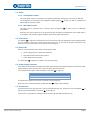
To recover the system factory default values such as network configuration, access password, working mode,
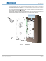
audio parameters…please keep pressed the recovery button for 6 seconds ( 7 in Figure 4).
1.9 Input contact connector
The input contact is “normally open” between the 2 pins male connector terminals (
following pin-out:
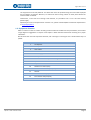
Pin
Signal
Description
1
IN+
Input
2
IN-
Ground for input
8
in Figure 4), with the
The input contact activation is carried out by joining the corresponding line (IN+) with the common (IN-).
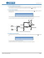
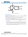
The opto-isolated input internal electrical scheme of is shown in the following figure:
Figure 5. Electrical scheme of the input contact
1.10 Output contact connector
The output contact is a free-of-voltage dry contact between the two male connector terminals (
4):
Pin
Signal
9
in Figure
Description
1
OUT_A
Output A
2
OUT_B
Output B
This contact supports a maximum current of 1A.
The internal structure of the “normally open” relay output is the one shown in Figure 6.
EQUITEL – E451 Technical manual
Page 7