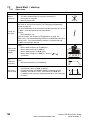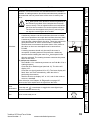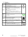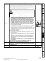
1
Field wiring
Size 0 to 4
• Class 1 60/75°C (140/167°F) copper wire only is used in the installation
Size 5 and 6
• Class 1 75°C (167°F) copper wire only is used in the installation
Field wiring connectors
Sizes 4 to 6
• UL listed wire connectors are used for terminating power circuit field wiring, e.g.
Ilsco TA series
AC supply specification
The drive is suitable for use in a circuit capable of delivering not more than 100,000rms
symmetrical Amperes at 264Vac rms maximum (200V drives), 528Vac rms maximum
(400V drives) or 600Vac rms maximum (575V and 690V drives).
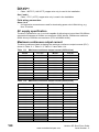
Maximum continuous output current
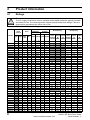
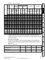
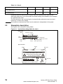
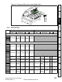
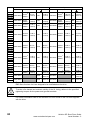
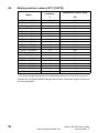
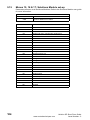
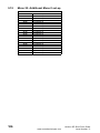
The drive models are listed as having the maximum continuous output currents (FLC)
shown in Table 11-1, Table 11-2, Table 11-3 and Table 11-4.
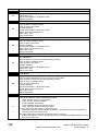
Table 11-1
FLC (A)
Model
FLC (A)
0201
0202
0203
0204
0205
1201
1202
1203
1204
2.2
3.1
4.0
5.7
7.5
5.2
6.8
9.6
11
2201
2202
2203
3201
3202
4201
4202
4203
5201
5202
15.5
22
28
42
54
68
80
104
130
154
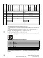
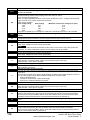
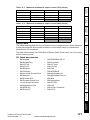
Table 11-2
120
Maximum continuous output current (200V drives)
Model
Maximum continuous output current (400V drives)
Model
FLC (A)
Model
FLC (A)
0401
0402
0403
0404
0405
1401
1402
1403
1404
1405
1406
1.3
1.7
2.1
3.0
4.2
2.8
3.8
5.0
6.9
8.8
11
2401
2402
2403
2404
3401
3402
3403
4401
4402
4403
5401
5402
6401
6402
15.3
21
29
29
35
43
56
68
83
104
138
168
205
236
www.controltechniques.com
Unidrive SP Short Form Guide
Issue Number: 2