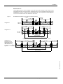
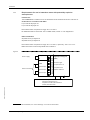
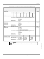
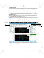
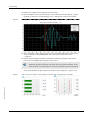
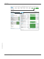
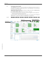
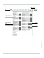
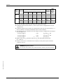
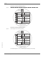
1
Title OPERATING INSTRUCTIONS FLOWSIC600 Ultrasonic Gas Flow Meter Ultrasonic Gas Flow Meter for Custody Transfer and Process Applications MEPAFLOW600 CBM and Firmware V3.6.xx Document Information Glossary Product Product name: Abbreviations used in this manual FLOWSIC600 actual (under operating/flowing conditions) AGC Automatic Gain Control Document ID Title: Part No.: Version: Release: ANSI American National Standards Institute Operating Instructions FLOWSIC600 8010125 4.0 2014-09 ASCII American Standard Code for Information Interchange ASME American Society of Mechanical Engineers ATEX Publisher SICK AG Erwin-Sick-Str. 1 Tel.: Fax: E-mail: Atmosphères Explosifs: Abbreviation for European standards that govern safety in potentially explosive atmospheres · D-79183 Waldkirch · Germany +49 7641 469-0 +49 7641 469-11 49 [email protected] AWG American Wire Gage CBM Condition Based Maintenance CSA Canadian Standards Association DC Direct Current Place of Manufacture SICK Engineering GmbH Bergener Ring 27 · D-01458 Ottendorf-Okrilla · Germany DIN Deutsches Institut für Normung DN Nominal Diameter (internal) DSP Digital Signal Processor Trademarks IBM is a trademark of the International Business Machine Corporation. MS-DOS is a trademark of the Microsoft Corporation. Windows is a trademark of the Microsoft Corporation. Other product names used in this document may also be trademarks and are only used for identification purposes. EC European Community EMC Electro Magnetisc Ccompatibility EN Euro Norm (European Standard) Guarantee Information Specified product characteristics and technical data do not serve as guarantee declarations. © SICK AG. All rights reserved. 2 act. EVC Electronic Volume Corrector Ex Potentially explosive atmosphere HART Communication interface IEC International Electrotechnical Commission IECEx EC system for certification in accordance with standards for devices for use in potentially explosive atmospheres LCD Liquid Crystal Display LED Light Emitting Diode MDR Manufacturer Data Record MEPAFLOW Menu-assisted Parameterization and Diagnosis for FLOWSIC600 NAMUR Normenarbeitsgemeinschaft für Mess- und Regeltechnik in der chemischen Industrie (now "Interessengemeinschaft Prozessleittechnik der chemischen und pharmazeutischen Industrie"; ~ Association for Instrumentation and Control Standards in the Chemical Industry) norm. normalized/corrected (under standard conditions) OI Operating Instructions OIML Organisation Internationale de Metrologie Legale PC Personal Computer PTB Physikalisch Technical Bundesanstalt (~ Federal Metrology Office in Germany) Reg. # Register number RTU Remote Terminal Unit SNR Signal Noise Ratio SPU Signal Processing Unit TI Technical Information VDE Verband der Elektrotechnik Elektronik Informationstechnik (~ Association of German Electrical Engineers) FLOWSIC600 · Operating Instructions · 8010125 V 4.0 · © SICK AG Warning Symbols Hazard (general) Hazard in potentially explosive atmospheres Hazard by voltage Warning Levels / Signal Words WARNING Risk or hazardous situation which could result in severe personal injury or death. CAUTION Hazard or unsafe practice which could result in personal injury or property damage. NOTICE Hazard which could result in property damage. Information Symbols Information about the use in potentially explosive atmospheres Important technical information for this product Important information on electric or electronic functions Supplementary information Link to information at another place FLOWSIC600 · Operating Instructions · 8010125 V 4.0 · © SICK AG 3 Contents 4 Contents 1 Important Information . . . . . . . . . . . . . . . . . . . . . . . . . . . . . . . . . . . . . . . . . . . . . . . 7 1.1 About this document . . . . . . . . . . . . . . . . . . . . . . . . . . . . . . . . . . . . . . . . . . . . . . . . . . . . . . . . . 8 1.2 Scope of document. . . . . . . . . . . . . . . . . . . . . . . . . . . . . . . . . . . . . . . . . . . . . . . . . . . . . . . . . . . 8 1.3 1.3.1 Safety instructions . . . . . . . . . . . . . . . . . . . . . . . . . . . . . . . . . . . . . . . . . . . . . . . . . . . . . . . . . . . 9 Intended use of the equipment . . . . . . . . . . . . . . . . . . . . . . . . . . . . . . . . . . . . . . . . . . . . . 9 1.4 Authorized staff . . . . . . . . . . . . . . . . . . . . . . . . . . . . . . . . . . . . . . . . . . . . . . . . . . . . . . . . . . . . . . 9 1.5 General safety instructions and protective measures . . . . . . . . . . . . . . . . . . . . . . . . . . . 10 1.6 Dangers due to hot, corrosive and explosive gases and high pressure . . . . . . . . . . . . 10 1.7 Dangers due to heavy loads . . . . . . . . . . . . . . . . . . . . . . . . . . . . . . . . . . . . . . . . . . . . . . . . . . 11 1.8 Environmental information and instructions for disposal . . . . . . . . . . . . . . . . . . . . . . . . 11 2 Product Description . . . . . . . . . . . . . . . . . . . . . . . . . . . . . . . . . . . . . . . . . . . . . . . . . . 13 2.1 2.1.1 2.1.2 2.1.3 System components . . . . . . . . . . . . . . . . . . . . . . . . . . . . . . . . . . . . . . . . . . . . . . . . . . . . . . . . . Meter body. . . . . . . . . . . . . . . . . . . . . . . . . . . . . . . . . . . . . . . . . . . . . . . . . . . . . . . . . . . . . . . Ultrasonic transducers . . . . . . . . . . . . . . . . . . . . . . . . . . . . . . . . . . . . . . . . . . . . . . . . . . . . Signal processing unit . . . . . . . . . . . . . . . . . . . . . . . . . . . . . . . . . . . . . . . . . . . . . . . . . . . . . 14 14 15 15 2.2 2.2.1 2.2.2 2.2.3 Operating modes, meter states and signal output . . . . . . . . . . . . . . . . . . . . . . . . . . . . . . Operation mode and configuration mode. . . . . . . . . . . . . . . . . . . . . . . . . . . . . . . . . . . . Meter states . . . . . . . . . . . . . . . . . . . . . . . . . . . . . . . . . . . . . . . . . . . . . . . . . . . . . . . . . . . . . Output of pulse signals and status information . . . . . . . . . . . . . . . . . . . . . . . . . . . . . . 16 16 17 18 2.3 Self-diagnosis with User Warnings . . . . . . . . . . . . . . . . . . . . . . . . . . . . . . . . . . . . . . . . . . . . 20 2.4 2.4.1 2.4.2 2.4.3 2.4.4 Data handling in the FLOWSIC600 . . . . . . . . . . . . . . . . . . . . . . . . . . . . . . . . . . . . . . . . . . . . Integrated volume counters. . . . . . . . . . . . . . . . . . . . . . . . . . . . . . . . . . . . . . . . . . . . . . . . Logbooks . . . . . . . . . . . . . . . . . . . . . . . . . . . . . . . . . . . . . . . . . . . . . . . . . . . . . . . . . . . . . . . . DataLogs . . . . . . . . . . . . . . . . . . . . . . . . . . . . . . . . . . . . . . . . . . . . . . . . . . . . . . . . . . . . . . . . Diagnostics Comparison Log . . . . . . . . . . . . . . . . . . . . . . . . . . . . . . . . . . . . . . . . . . . . . . . 2.5 2.5.1 2.5.2 MEPAFLOW600 CBM . . . . . . . . . . . . . . . . . . . . . . . . . . . . . . . . . . . . . . . . . . . . . . . . . . . . . . . . 25 System requirements . . . . . . . . . . . . . . . . . . . . . . . . . . . . . . . . . . . . . . . . . . . . . . . . . . . . . 25 Overview . . . . . . . . . . . . . . . . . . . . . . . . . . . . . . . . . . . . . . . . . . . . . . . . . . . . . . . . . . . . . . . . . 26 3 Installation . . . . . . . . . . . . . . . . . . . . . . . . . . . . . . . . . . . . . . . . . . . . . . . . . . . . . . . . . . . . . 29 3.1 3.1.1 3.1.2 General notes . . . . . . . . . . . . . . . . . . . . . . . . . . . . . . . . . . . . . . . . . . . . . . . . . . . . . . . . . . . . . . 30 Delivery . . . . . . . . . . . . . . . . . . . . . . . . . . . . . . . . . . . . . . . . . . . . . . . . . . . . . . . . . . . . . . . . . . 30 Transport and storage. . . . . . . . . . . . . . . . . . . . . . . . . . . . . . . . . . . . . . . . . . . . . . . . . . . . . 31 3.2 3.2.1 3.2.2 Installation . . . . . . . . . . . . . . . . . . . . . . . . . . . . . . . . . . . . . . . . . . . . . . . . . . . . . . . . . . . . . . . . . 32 Measuring location . . . . . . . . . . . . . . . . . . . . . . . . . . . . . . . . . . . . . . . . . . . . . . . . . . . . . . . 32 Installation configurations . . . . . . . . . . . . . . . . . . . . . . . . . . . . . . . . . . . . . . . . . . . . . . . . . 33 3.3 3.3.1 3.3.2 3.3.3 Mechanical installation . . . . . . . . . . . . . . . . . . . . . . . . . . . . . . . . . . . . . . . . . . . . . . . . . . . . . . Choosing flanges, seals and other parts . . . . . . . . . . . . . . . . . . . . . . . . . . . . . . . . . . . . Mounting the FLOWSIC600 in the piping . . . . . . . . . . . . . . . . . . . . . . . . . . . . . . . . . . . . SPU alignment . . . . . . . . . . . . . . . . . . . . . . . . . . . . . . . . . . . . . . . . . . . . . . . . . . . . . . . . . . . 35 35 36 37 3.4 3.4.1 3.4.2 3.4.3 3.4.4 3.4.5 3.4.6 Electrical installation . . . . . . . . . . . . . . . . . . . . . . . . . . . . . . . . . . . . . . . . . . . . . . . . . . . . . . . . General information. . . . . . . . . . . . . . . . . . . . . . . . . . . . . . . . . . . . . . . . . . . . . . . . . . . . . . . Cable specifications . . . . . . . . . . . . . . . . . . . . . . . . . . . . . . . . . . . . . . . . . . . . . . . . . . . . . . Checking the cable loops . . . . . . . . . . . . . . . . . . . . . . . . . . . . . . . . . . . . . . . . . . . . . . . . . . Terminal enclosure on the SPU. . . . . . . . . . . . . . . . . . . . . . . . . . . . . . . . . . . . . . . . . . . . . Operating the FLOWSIC600 in non-hazardous areas . . . . . . . . . . . . . . . . . . . . . . . . . Requirements for use in hazardous areas with potentially explosive atmospheres . . . . . . . . . . . . . . . . . . . . . . . . . . . . . . . . . . . . . . . . . . . . . . . . . . . . . . . . . . . . . 38 38 40 41 42 44 21 21 22 23 24 45 FLOWSIC600 · Operating Instructions · 8010125 V 4.0 · © SICK AG Contents 4 Commissioning . . . . . . . . . . . . . . . . . . . . . . . . . . . . . . . . . . . . . . . . . . . . . . . . . . . . . . . . 55 4.1 General notes . . . . . . . . . . . . . . . . . . . . . . . . . . . . . . . . . . . . . . . . . . . . . . . . . . . . . . . . . . . . . . . 56 4.2 4.2.1 4.2.2 Connecting the FLOWSIC600 to a PC or laptop . . . . . . . . . . . . . . . . . . . . . . . . . . . . . . . . . 57 Connecting the FLOWSIC600 via RS485 / RS232 cable . . . . . . . . . . . . . . . . . . . . . . 57 Connecting the FLOWSIC600 via RS485/USB converter . . . . . . . . . . . . . . . . . . . . . . 58 4.3 4.3.1 4.3.2 4.3.3 4.3.4 4.3.5 Connecting to the FLOWSIC600 with MEPAFLOW600 CBM . . . . . . . . . . . . . . . . . . . . . . 59 Starting MEPAFLOW600 CBM . . . . . . . . . . . . . . . . . . . . . . . . . . . . . . . . . . . . . . . . . . . . . . 59 Choosing a User Access Level . . . . . . . . . . . . . . . . . . . . . . . . . . . . . . . . . . . . . . . . . . . . . . 59 Creating a new meter entry in the meter database . . . . . . . . . . . . . . . . . . . . . . . . . . . 60 Online connection: Direct serial . . . . . . . . . . . . . . . . . . . . . . . . . . . . . . . . . . . . . . . . . . . . 61 Online connection: Ethernet. . . . . . . . . . . . . . . . . . . . . . . . . . . . . . . . . . . . . . . . . . . . . . . . 63 4.4 4.4.1 Identification . . . . . . . . . . . . . . . . . . . . . . . . . . . . . . . . . . . . . . . . . . . . . . . . . . . . . . . . . . . . . . . . 65 Checking identification, operation / design data and firmware version . . . . . . . . . 65 4.5 4.5.1 Field setup. . . . . . . . . . . . . . . . . . . . . . . . . . . . . . . . . . . . . . . . . . . . . . . . . . . . . . . . . . . . . . . . . . 67 Disconnecting from the meter and closing the session. . . . . . . . . . . . . . . . . . . . . . . . 68 4.6 4.6.1 4.6.2 4.6.3 Function test . . . . . . . . . . . . . . . . . . . . . . . . . . . . . . . . . . . . . . . . . . . . . . . . . . . . . . . . . . . . . . . . 69 Function test on FLOWSIC600 with LCD front panel . . . . . . . . . . . . . . . . . . . . . . . . . . 69 Function test on FLOWSIC600 with LED front panel . . . . . . . . . . . . . . . . . . . . . . . . . . 69 Function test with MEPAFLOW600 CBM . . . . . . . . . . . . . . . . . . . . . . . . . . . . . . . . . . . . . 70 4.7 4.7.1 4.7.2 4.7.3 Optional advanced setup . . . . . . . . . . . . . . . . . . . . . . . . . . . . . . . . . . . . . . . . . . . . . . . . . . . . . 72 Configuration and activation of User Warnings . . . . . . . . . . . . . . . . . . . . . . . . . . . . . . . 72 Configuration of DataLogs . . . . . . . . . . . . . . . . . . . . . . . . . . . . . . . . . . . . . . . . . . . . . . . . . 74 Configuring and using the Diagnostics Comparison Log . . . . . . . . . . . . . . . . . . . . . . . 78 4.8 Activation of path compensation . . . . . . . . . . . . . . . . . . . . . . . . . . . . . . . . . . . . . . . . . . . . . . 83 4.9 Sealing . . . . . . . . . . . . . . . . . . . . . . . . . . . . . . . . . . . . . . . . . . . . . . . . . . . . . . . . . . . . . . . . . . . . . 84 4.10 Documentation. . . . . . . . . . . . . . . . . . . . . . . . . . . . . . . . . . . . . . . . . . . . . . . . . . . . . . . . . . . . . . 84 5 Maintenance . . . . . . . . . . . . . . . . . . . . . . . . . . . . . . . . . . . . . . . . . . . . . . . . . . . . . . . . . . . 85 5.1 General. . . . . . . . . . . . . . . . . . . . . . . . . . . . . . . . . . . . . . . . . . . . . . . . . . . . . . . . . . . . . . . . . . . . . 86 5.2 5.2.1 5.2.2 5.2.3 5.2.4 Routine checks. . . . . . . . . . . . . . . . . . . . . . . . . . . . . . . . . . . . . . . . . . . . . . . . . . . . . . . . . . . . . . 87 Comparing theoretical and measured Speed of Sound (SOS) . . . . . . . . . . . . . . . . . . 87 Checking the meter health . . . . . . . . . . . . . . . . . . . . . . . . . . . . . . . . . . . . . . . . . . . . . . . . . 89 Time synchronization . . . . . . . . . . . . . . . . . . . . . . . . . . . . . . . . . . . . . . . . . . . . . . . . . . . . . . 90 Battery lifespan / capacity . . . . . . . . . . . . . . . . . . . . . . . . . . . . . . . . . . . . . . . . . . . . . . . . . 91 5.3 Maintenance report. . . . . . . . . . . . . . . . . . . . . . . . . . . . . . . . . . . . . . . . . . . . . . . . . . . . . . . . . . 92 5.4 5.4.1 5.4.2 Optional data download . . . . . . . . . . . . . . . . . . . . . . . . . . . . . . . . . . . . . . . . . . . . . . . . . . . . . . 94 Logbook check. . . . . . . . . . . . . . . . . . . . . . . . . . . . . . . . . . . . . . . . . . . . . . . . . . . . . . . . . . . . 94 DataLogs check . . . . . . . . . . . . . . . . . . . . . . . . . . . . . . . . . . . . . . . . . . . . . . . . . . . . . . . . . . . 96 6 Troubleshooting . . . . . . . . . . . . . . . . . . . . . . . . . . . . . . . . . . . . . . . . . . . . . . . . . . . . . . . 99 6.1 General troubleshooting . . . . . . . . . . . . . . . . . . . . . . . . . . . . . . . . . . . . . . . . . . . . . . . . . . . 100 6.2 6.2.1 6.2.2 6.2.3 6.2.4 Indication of meter states, system alarms and warnings. . . . . . . . . . . . . . . . . . . . . . . . 100 Checking the "Meter Status" window . . . . . . . . . . . . . . . . . . . . . . . . . . . . . . . . . . . . . . . 101 Checking the "User Warnings" window. . . . . . . . . . . . . . . . . . . . . . . . . . . . . . . . . . . . . . 103 Checking the diagnostic meter values . . . . . . . . . . . . . . . . . . . . . . . . . . . . . . . . . . . . . . 104 Battery lifespan / capacity . . . . . . . . . . . . . . . . . . . . . . . . . . . . . . . . . . . . . . . . . . . . . . . . 106 6.3 Generation of a Diagnosis session . . . . . . . . . . . . . . . . . . . . . . . . . . . . . . . . . . . . . . . . . . . 107 6.4 Meter connection troubleshooting. . . . . . . . . . . . . . . . . . . . . . . . . . . . . . . . . . . . . . . . . . . . 108 FLOWSIC600 · Operating Instructions · 8010125 V 4.0 · © SICK AG 5 Contents 6 7 Appendix . . . . . . . . . . . . . . . . . . . . . . . . . . . . . . . . . . . . . . . . . . . . . . . . . . . . . . . . . . . . . . 109 7.1 7.1.1 7.1.2 7.1.3 7.1.4 Conformities and technical data . . . . . . . . . . . . . . . . . . . . . . . . . . . . . . . . . . . . . . . . . . . . . 110 CE certificate . . . . . . . . . . . . . . . . . . . . . . . . . . . . . . . . . . . . . . . . . . . . . . . . . . . . . . . . . . . . 110 Standard compatibility and type approval . . . . . . . . . . . . . . . . . . . . . . . . . . . . . . . . . . 110 WELMEC compliance. . . . . . . . . . . . . . . . . . . . . . . . . . . . . . . . . . . . . . . . . . . . . . . . . . . . . 110 Technical data . . . . . . . . . . . . . . . . . . . . . . . . . . . . . . . . . . . . . . . . . . . . . . . . . . . . . . . . . . 112 7.2 7.2.1 Logbooks. . . . . . . . . . . . . . . . . . . . . . . . . . . . . . . . . . . . . . . . . . . . . . . . . . . . . . . . . . . . . . . . . . 118 Overview of event entries in meter logbooks. . . . . . . . . . . . . . . . . . . . . . . . . . . . . . . . 118 7.3 SPU terminal assignment . . . . . . . . . . . . . . . . . . . . . . . . . . . . . . . . . . . . . . . . . . . . . . . . . . . 122 7.4 Connection diagrams for operating the FLOWSIC600 in hazardous areas in accordance with North American Requirements (NEC, CEC) . . . . . . . . . . . . . . . . . . . . 124 7.5 7.5.1 7.5.2 Wiring examples . . . . . . . . . . . . . . . . . . . . . . . . . . . . . . . . . . . . . . . . . . . . . . . . . . . . . . . . . . . 130 Intrinsically safe installation . . . . . . . . . . . . . . . . . . . . . . . . . . . . . . . . . . . . . . . . . . . . . . 130 Non-intrinsically safe installation . . . . . . . . . . . . . . . . . . . . . . . . . . . . . . . . . . . . . . . . . . 131 7.6 Sealing plan . . . . . . . . . . . . . . . . . . . . . . . . . . . . . . . . . . . . . . . . . . . . . . . . . . . . . . . . . . . . . . . 132 FLOWSIC600 · Operating Instructions · 8010125 V 4.0 · © SICK AG Important Information FLOWSIC600 1 Important Information Subject to change without notice About this document Scope of document Safety instructions Authorised staff General safety instructions and protective measures Dangers due to hot, corrosive and explosive gases and high pressure Dangers due to heavy loads Environmental information and instructions for disposal FLOWSIC600 · Operating Instructions · 8010125 V 4.0 · © SICK AG 7 Important Information 1. 1 About this document This manual describes the FLOWSIC600 measuring system, which is used to determine the volumetric flow rate, volume and speed of sound in gases transported in pipelines. It provides general information on the measuring method employed, design and function of the entire system and its components, on planning, assembly, installation, calibration commissioning, maintenance and troubleshooting. A detailed description of the various system capabilities, options and settings which will assist in optimizing the meter configuration for a specific application is also included. This manual covers standard applications which conform with the technical data specified. Additional information and assistance for special applications are available from your SICK representative. However, it is generally recommended that advantage be taken of qualified consulting services provided by SICK experts for your specific application. This manual is a part of the FLOWSIC600 device documentation. Documentation available via www.FLOWSIC600.com or from your local representative: ● FLOWSIC600 MODBUS specification document ● FLOWSIC600 HARTbus specification document ● FLOWSIC600 Technical Bulletin ENCODER Output Documentation available from your local representative after training: ● FLOWSIC600 service manual ● FLOWSIC600 extraction tool operating instructions 1. 2 Scope of document This document applies to meters with firmware version 3.6.00 or higher and extended memory for the storage of e.g. hourly and daily mean values. The software description in this document applies to MEPAFLOW600 CBM V1.3.00. Measurand Volume at flowing conditions Volume at base conditions Error volume at flowing conditions Error volume at base conditions Total volume at flowing conditions Volume flow at flowing conditions Volume flow at base conditions Mass counter Error Mass Mass flow at base conditions 8 Basic abbreviations and units for FLOWSIC600 Vf m³ acf Vb Nm³ scf Ef m³ acf Eb Nm³ scf Vo m³ acf Qf m³/h acf/h Qb Nm³/h scf/h M t lbs Me t lbs Mf t/h lbs/h Abbreviations used for LCD-Display of SPU MEPAFLOW600 CBM software Vf Vb Ef Eb Vo Qf Qb M M M Vf Vb Ef Eb Vo Qf Qb M M M m³ m³ m³ m³ m³ m³/h m³/h t t t/h cf cf cf cf cf cf/h cf/h lbs lbs lbs/h m³ Nm³ m³ Nm³ m³ m³/h Nm³/h t t t/h acf scf acf scf acf acfh scfh lbs lbs lbs/h FLOWSIC600 · Operating Instructions · 8010125 V 4.0 · © SICK AG Subject to change without notice The following terms will be used for measurands: Important Information 1.3 Safety instructions 1.3.1 Intended use of the equipment The FLOWSIC600 measuring system is used for measuring the actual volumetric flow rate of gases transported in pipelines. It can be used for measuring the actual corrected volume and the speed of sound in gases. The measuring system shall only be used as specified by the manufacturer and as set forth below. Always observe the following information: ● Make sure the use of the equipment complies with the technical data, information about the permitted use, assembly and installation specifications and ambient as well as operating conditions. Relevant information is provided in the order documentation, type plate, certification documents and this manual. ● Any actions for the purpose of maintaining the value of the equipment, e.g. service and inspection, transport and storage etc., shall be performed as specified. ● Do not expose the equipment to mechanical stress, such as pigging. ● The flooding of the FLOWSIC600 with any liquid (e.g. for pressure or leakage tests) is deemed improper use. The consequences of such actions can not be foreseen or estimated. Improper use may result in failure of the ultrasonic transducers and consequently, failure of the entire flow meter. Should it be necessary to flood the FLOWSIC600, please contact the manufacturer prior to doing so. In addition, the following instructions must be strictly adhered to: WARNING: The pressure during flooding may not exceed more than 1,2 times the nominal pressure (when transducers are assembled). Subject to change without notice 1.4 Authorized staff Persons responsible for safety shall ensure the following: ● Any work on the measuring system shall only be carried out by qualified staff and must be approved by skilled staff responsible for the plant. Due to their professional training, knowledge and vocational experience, as well as their knowledge of the relevant standards, regulations, health and safety regulations and equipment conditions, qualified persons shall be assigned by the person responsible for personal and plant safety to carry out such work. Qualified persons must be able to identify possible dangers and to take preventive action in due time. Skilled persons are defined in DIN VDE 0105 and IEC 364, or comparable standards. ● Skilled persons shall have precise knowledge of process-specific dangers, e.g. due to the effects of hot, toxic and pressurized gases, gas-liquid mixtures and other process media, and of the design and working principle of the measuring system and shall have received and be able to document appropriate training. ● In hazardous areas with potentially explosive atmospheres, wiring and installation shall only be carried out by staff trained according to EN /IEC 60079-14 and according to national regulations. FLOWSIC600 · Operating Instructions · 8010125 V 4.0 · © SICK AG 9 Important Information 1. 5 General safety instructions and protective measures Using the equipment for any purpose other than that intended by the manufacturer, or improper operation may result in injuries and damage to the equipment. Read this section and the notes and warnings in the individual sections of this manual carefully and observe the instructions contained therein when carrying out any work on the FLOWSIC600 measuring system. General instructions to be adhered to: ● Always comply with the statutory provisions and the associated technical rules and regulations relevant to the equipment when preparing for and carrying out any work on the measuring system. Pay particular attention to potentially hazardous aspects of the equipment, such as pressurized piping and explosion protection zones. Always observe the relevant regulations. ● Always consider local and equipment-specific conditions and process-specific dangers when carrying out any work on the equipment. ● Operating and service instructions and equipment documentation shall always be available on site. Always observe the safety instructions and notes on the prevention of injuries and damage given in these manuals. ● Ensure appropriate protective accessories are available in sufficient supply. Always use such protective accessories. Check that appropriate safety devices are fitted and working correctly. 1. 6 Dangers due to hot, corrosive and explosive gases and high pressure The FLOWSIC600 measuring system is directly integrated into gas-carrying pipelines. The operating company is responsible for safe operation and for complying with additional national and company-specific regulations. WARNING: In plants with toxic and explosive gases, high pressure or high temperatures, the FLOWSIC600 measuring system shall only be installed or removed after the associated piping has been isolated and depressurized (i.e. vented to atmosphere). The same applies to repair and service work which involves opening any pressurized component or the explosion-proof signal processing unit (SPU). Subject to change without notice NOTICE: Design, manufacture and inspection of the FLOWSIC600 measuring system is performed in compliance with the safety requirements set forth in the European Pressure Equipment Directive 97/23/EC. 10 FLOWSIC600 · Operating Instructions · 8010125 V 4.0 · © SICK AG Important Information 1.7 Dangers due to heavy loads The FLOWSIC600 measuring system must be safely attached to the carrying structure when being transported and installed. WARNING: ● Only use lifting gear and equipment (e.g. lifting straps) which is suitable for the weight to be lifted. Max. load information can be found on the type plate of the lifting gear. ● The eye bolts attached to the meter body are suitable for the transport of the measuring device. However, additional loads (e.g. blind covers, filling for pressure tests or associated piping) must not be lifted and transported together with the measuring system without the use of additional support from the lifting gear. ● Never attach lifting gear to the signal processing unit or its mounting bracket and avoid contact between these parts and the lifting gear. 1.8 Environmental information and instructions for disposal Subject to change without notice The FLOWSIC600 components are easily disassembled and do not contain toxic, radioactive or any other environmentally hazardous materials. The instrument consists primarily of steel, stainless steel, plastic and aluminium, and consequently there are few restrictions for disposal, except for the printed circuit boards, which must be disposed of as electronic scrap. FLOWSIC600 · Operating Instructions · 8010125 V 4.0 · © SICK AG 11 Subject to change without notice Important Information 12 FLOWSIC600 · Operating Instructions · 8010125 V 4.0 · © SICK AG Product Description FLOWSIC600 2 Product Description Subject to change without notice System components Operating states, meter states and signal output Self-Diagnosis with User Warnings Data Handling in the FLOWSIC600 MEPAFLOW600 CBM FLOWSIC600 · Operating Instructions · 8010125 V 4.0 · © SICK AG 13 Product Description 2. 1 System components The FLOWSIC600 measuring system consists of the following hardware components: ● Meter body ● Ultrasonic transducers ● Signal processing unit (SCU) The MEPAFLOW600 CBM software is the user interface used to facilitate configuration and diagnosis ( pg. 25, 2.5). Figure 1 FLOWSIC600 SPU Lifting eye Pressure tap Flange Cover cap Marking for direction of flow (forward) Position of the ultrasonic transducers (cover cap taken off) Meter body Meter body The meter body consists of a mid section for mounting the ultrasonic transducers, with flanges on either end. The meter body is made of a single-piece casting or forging, which is machined on precision equipment to ensure high reproducibility of the geometric parameters. The internal diameter, design of the sealing surface, and standard dimensions of the flanges are in accordance with the specifications in the key code. The meter body material is chosen to suit customer requirements. Standard meter bodies are available in carbon steel, low temperature carbon steel and stainless steel. The meter bodies can be delivered in several nominal sizes ( pg. 112, 7.1.4). 14 FLOWSIC600 · Operating Instructions · 8010125 V 4.0 · © SICK AG Subject to change without notice 2.1.1 Product Description 2.1.2 Ultrasonic transducers The FLOWSIC600 ultrasonic transducers are optimized to suit your application requirements. The high quality of the transducer design provides the basis for accurate and highly stable propagation time measurements with nanosecond precision. These transducers are of an intrinsically safe design ("ia", with Equipment Protection Level Ga). 2.1.3 Signal processing unit The Signal processing unit (SPU) contains all the electrical and electronic components for controlling the ultrasonic transducers. It generates transmission signals and analyzes the received signals to calculate the measuring values. The SPU also contains several interfaces for communication with a PC or standardized process control system. The volume counters, log books (errors, warnings, parameter changes) and datalogs are stored in non-volatile data memory (FRAM) together with a time stamp (Logbooks pg. 118, 7.2.) On system restart, the counter readings that were last saved are restored as the start values for the volume counters. The FRAM backup provides an unlimited number of writing cycles and protects the saved data for a minimum of 10 years. The SPU is equipped with a front panel containing a two-line LCD to display current measured values, diagnostics and logbook information ( Figure 2). An LED display is optionally available. The values to be displayed can be selected using a magnetic pen without removal of the window cover . Figure 2 FLOWSIC600 front panel LCD Measured values Control buttons for the magnetic pen Subject to change without notice Control buttons for manual use The power supply and interface terminals are located on the back of the SPU in a separate terminal section of the enclosure ( pg. 42, 3.4.4). The electronics are mounted in the SPU enclosure certified to EN / IEC 60079-1 with protection type "d" (flameproof enclosure). The transducer circuits are of an intrinsically safe design ("ia", with Equipment Protection Level Ga). FLOWSIC600 · Operating Instructions · 8010125 V 4.0 · © SICK AG 15 Product Description 2. 2 Operating modes, meter states and signal output The FLOWSIC600 has two operating modes ( pg. 16, 2.2.1): ● Operation ● Configuration Mode In Operation Mode, the meter can have the following meter states ( pg. 17, 2.2.2): ● Measurement valid ● Chck request ● Data invalid 2.2.1 Operation mode and configuration mode The meter can be operated by the user in two modes: Operation Mode or Configuration Mode. Operation Mode In Operation Mode, the meter runs in one of the three aforementioned meter states, depending on the measuring conditions. Configuration Mode The Configuration Mode is used to modify parameters that directly influence the measurement and to test the system and output signals. Configuration Mode forces the meter into the meter status "Data invalid" and the digital output "Measurement valid" is deactivated. Invalid measured values may be produced. The system continues operation using the current sample rate and executes all calculations as in the Operation Mode. Frequency output and analog output may represent test values and do thus not necessarily indicate measured values. Any parameter modifications are applied immediately to the running calculations with the following exception: changes of the sample rate or of the configuration of the serial interface are applied after the meter is switched to Operation Mode. Subject to change without notice If the meter is in Configuration Mode and there have been no activities either on the LCD display or via MEPAFLOW600 CBM for more than 15 minutes, the meter automatically switches to Operation Mode. 16 FLOWSIC600 · Operating Instructions · 8010125 V 4.0 · © SICK AG Product Description Meter states 2.2.2.1 Status: Measurement valid The meter status "Measurement" is the standard meter status of the FLOWSIC600. Frequency outputs and current output are updated cyclically and indicate the actual volume and volume flow rate. In addition, the analog signal can indicate the actual flow rate, corrected volumetric flow rate, SOS (speed of sound) or VOG (velocity of gas). The digital output "Direction of flow" is updated in accordance with the direction of the volumetric flow. The digital output "Measurement valid" (active) represents the status of the measurement. Positive (forward) and negative (reverse) volumetric flow rates are integrated and saved in separate internal memory sections. The MODBUS interface allows the query of all parameters and signals at any time without interfering with the function of the system. Each measurement initiated by the system controller includes one full transit time measurement with, and one against the direction of flow on each path. The result of each measurement is written to a mean value memory to be used in further calculations. The size of this memory block and thus the device response delay can be modified through the parameter in register #3502 "AvgBlockSize". If no result can be calculated due to poor signal quality, this measurement is registered as an invalid attempt in the mean value memory. The mean value is formed in a variable averaging process including all valid measured values in the memory. If the number of invalid measurements on a path exceeds a predefined limit (Reg. #3514 „Performance“), the measuring system activates the meter status "Check request". 2.2.2.2 Status: Check request This meter status becomes active if one measuring path has failed and the adaptive path failure compensation has been activated. The multi-path FLOWSIC600 system is able to compensate for this failure. Measurement is continued with reduced accuracy and the volume is still counted in the volume counters. If a path fails while the path failure compensation is not active, the measuring system will activate the "Data invalid" status. Moreover the meter status "Check request" becomes active when the system alarms 2002 ("No HART communication to temperature transmitter"), 2003 ("No HART communication to pressure transmitter"), or 2004 ("Maximum pulse output frequency exceeded") become active (table pg. 118, 7.2.1). 2.2.2.3 Status: Data invalid If the quality of received signals is deficient in one or more measuring paths or the logbook is full or the measured value is out of the calibration range, the SPU must mark the measured value invalid and activate the meter status "Data invalid". The measured volume is counted in the error volume counter. However, the SPU will cyclically attempt to reestablish valid measurements. As soon as the signal quality and number of valid measurements meet the required criteria, the SPU will automatically change back to the "Measurement valid" or "Check request" status. Subject to change without notice 2.2.2 FLOWSIC600 · Operating Instructions · 8010125 V 4.0 · © SICK AG 17 Product Description 2.2.3 Output of pulse signals and status information NOTICE: TYPE APPROVAL Pulse output signals can be customized as shown in the following table. Table 1 Pulse output Output signal / LCD / port Pulse output signals Signal behavior Measurement status Check request status Configuration Mode Data invalid* Inverted with error signal ** Phase Positive shift flow rate 90 ° *** Negative flow rate Separate Positive outputs flow rate for reach direction Negative flow rate * The meter can be configured to output a fixed frequency if the meter has the status "Data invalid". The frequency to be output in this case can be configured (0-6 kHz) in Reg. #3034 "ErrorFreq". ** Default setting on delivery. *** Optional setting on customer request. The default setting for "Check request", "Configuration" and "Data invalid" is "normally closed". 18 FLOWSIC600 · Operating Instructions · 8010125 V 4.0 · © SICK AG Subject to change without notice Single pulse output *** Product Description Table 2 Status output Output signal / LCD / port "Check request" Status signal "Direction of flow" Status signal "Warning" LCD display Serial port RS485 Signal behavior Measurement status Check request status Status Status "active / inactive" * "active / inactive" * Compensation of Measurement valid path failure Status Status "active / inactive" * "active / inactive" * Positive or negative Positive or negative direction of flow direction of flow Status Status "active / inactive" * "active / inactive" * +V 123456 m³ -V 1234 m³ 1234 m³ E Configuration Mode Data invalid "undefined" "undefined" "undefined" "undefined" "undefined" "undefined" FLOWSIC600 Configuration +V 123456 m³ E -V 1234 m³ Display flashing Display flashing ● Measured value, diagnosis information and parameters ● Measuring data logging, diagnosis and configuration through the MEPAFLOW600 CBM software ● Connection with external process control equipment through implemented MODBUS protocol (data polling) Subject to change without notice *The "active" or "inactive" state can be assigned to the electric switch status "normally open" or "normally closed" by configuration in the MEPAFLOW600 CBM software (adjust settings for Reg. #5101 on the "Parameters" page.). The output signal designation is described inthe Technical Information. The LCD display can display measured values, parameters, messages and other information. A flashing letter in the upper right corner of the LCD display indicates that a logbook contains unacknowledged logbook entries. Depending on the type of entry this will be: ● "I" for Information ● "W" for Warning ● "E" for Error After acknowledging all new entries, the letter stops flashing. For details see pg. 94, 5.4.1. FLOWSIC600 · Operating Instructions · 8010125 V 4.0 · © SICK AG 19 Product Description 2. 3 Self-diagnosis with User Warnings During normal operation, the ratios of sound and path velocities, amplification values, performance, and signal-to-noise ratios are continuously monitored. If these values exceed set limits (customized User Warning limits), a warning signal will be generated. This allows immediate measures to be taken to address a problem which could potentially impact measurement quality. A message in the Warning Logbook documents the time of the event and the specific User Warning limit which was exceeded. ● The "Warning" signal does not affect the functionality of the meter. ● All User Warning parameters - except for the parameter ‘Min. VOG for warnings" - can be configured in the User Access Level "Operator" and without switching the meter to the Configuration Mode. A User Warning becomes active only if a User Warning limit has been continuously exceeded for a certain time (specified in the parameter "Warning duration and averaging for warnings" in the Configuration tab of User Warnings). During commissioning or operation, the User Warning limits can be adapted and activated or deactivated in the "User Warnings" window in MEPAFLOW600 CBM to suit individual application requirements ( pg. 72, 4.7.1). Figure 3 Button "User" in the MEPAFLOW600 CBM main system bar, "User Warnings" window Opens the "User Warnings" window System warnings see Technical Information Subject to change without notice Path warnings see Technical Information 20 FLOWSIC600 · Operating Instructions · 8010125 V 4.0 · © SICK AG Product Description 2.4 Data handling in the FLOWSIC600 2.4.1 Integrated volume counters The FLOWSIC600 is equipped with integrated volume counters which can be displayed both on the LCD display and in MEPAFLOW600 CBM. Integrated volume counters Volume counter Abbreviation Volume at flowing conditions (forward) + Vf Volume at flowing conditions (reverse) - Vf Error volume at flowing conditions (forward)1 + Ef Error volume at flowing conditions (reverse)1 - Ef Total volume at flowing conditions (forward) + Vo Total volume at flowing conditions (reverse) - Vo Total volume at flowing conditions (all) Vo Last hour/day registers Volume counter Abbreviation Forward volume of last hour Last hour forw. Reverse volume of last hour Last hour rev. Forward volume of last day Last day forw. Reverse volume of last day Last day rev. Additional counters in meters with integrated Electronic Volume Corrector (EVC) Volume counter Abbreviation Volume at base conditions (forward) + Vb Volume at base conditions (reverse) - Vb Error volume at base conditions (forward)1 + Eb Error volume at base conditions (reverse)1 - Eb Subject to change without notice Mass counters Mass counter Abbreviation Mass counter (forward) +M Mass counter (reverse) -M Mass total (forward) M+ Mass total (reverse) M- Error Mass (forward)1 Me+ Error mass (reverse)1 Me- 1 see Technical Information FLOWSIC600 · Operating Instructions · 8010125 V 4.0 · © SICK AG 21 Product Description 2.4.2 Logbooks Important system events are stored in three logbooks in the SPU memory of the meter. Each logbook entry consists of a running index number, the event, a time stamp and the acknowledgement status. Entries in Custody logbook [1] and Warning logbook [2] also include the volume counter readings valid at that time. The events are logged continuously in order of occurrence into one of the three logbooks: ● Logbook 1 (Custody logbook [1], max. 1000 entries) ● Logbook 2 (Warning logbook [2], max. 500 entries) ● Logbook 3 (Parameter logbook [3], max. 250 entries) Every logbook has its own index counter. Logbook entries are classified on the LCD display according to the event type. Event types in logbooks Display Event type E Error W Warning I Information A list of possible logbook entries can be found in the table ‘Overview of event entries‘ in the Appendix, see pg. 118, 7.2.1. Logbook overflow NOTICE: TYPE APPROVAL If a FLOWSIC600 is configured as a custody meter, the volume counters stop if Custody logbook [1] and/or Parameter Logbook [3] is full. The meter status "Data invalid" is activated. The measured values are now counted in the error volume counter. If the FLOWSIC600 is not configured as a custody meter, all logbooks are per default configured to be overflowing. This means the index number continues increasing, and after the logbook has reached its maximum number of entries, each new entry overwrites the oldest entry. If the logbook overflows, the oldest data will be lost. Regularly saving the logbook entries to the database via MEPAFLOW600 CBM ( pg. 94, 5.4.1) and deletion of entries in the meter itself prevents data loss. If entries are deleted via MEPAFLOW600 CBM, the logbook index counter on the meter is reset. Index counter overflow The index number displayed in the LCD display runs up to 9999 and then overflows. In case of an index overflow, all logbook entries are deleted and all logbook index counters reset. 22 FLOWSIC600 · Operating Instructions · 8010125 V 4.0 · © SICK AG Subject to change without notice Acknowledging entries Each entry can be acknowledged manually on the LCD display (see Technical Information) as well as in MEPAFLOW600 CBM ( pg. 95, 5.4.1.2). It is possible to acknowledge individual entries or all entries at once. : Product Description 2.4.3 DataLogs1 For firmware version 3.4.03 and higher, the FLOWSIC600 provides two DataLogs (Hourly Log and Daily Log). They save averaged measured values and are stored in the SPU‘s nonvolatile memory (FRAM). All data can be downloaded and exported to Excel files with MEPAFLOW600 CBM ( pg. 97, 5.4.2.1.). The following sections describe the default configuration of the DataLogs. The DataLogs can be configured to best suit your application pg. 75, 4.7.2.2. 2.4.3.1 Hourly Log The Hourly Log logs hourly diagnostic values by default (dataset type "Diagnostic Values", pg. 50, Table 11) for the forward flow. As long as the flow is valid and the VOG is above Vmin all diagnostic and flow values are averaged over one hour and saved every full hour. The Hourly Log stores these values for more than a month (38 days) by default. They are then overwritten with new values. 2.4.3.2 Daily Log The Daily Log logs the daily volume counter values by default (dataset type "Volume Counters" pg. 50, Table 12) for the forward flow. All flow values are averaged over one day and saved at the (configurable) Accounting Hour ( 2.8.3.6). The Daily Log stores these values for approximately 2 years by default (1 year and 361 days). They are then overwritten with new values. DataLog Storage Cycle Hourly Log and Daily Log can be configured to save entries in a storage cycle of: 3 min, 5 min, 15 min, 30 min, 1 hour, 12 hours or 24 hours. If a DataLog is set to a Storage cycle of 12 or 24 hours, the accounting hour takes effect. 2.4.3.3 DataLog storage behavior Hourly Log and Daily Log can be configured for the following storage behavior: ● Overflow (Default) ● Stopping Storage Behavior "Stopping" If a DataLog is configured with the storage behavior "Stopping", a warning will be shown in the Meter Status Table when the DataLog is full. See pg. 90, 5.2.3. Subject to change without notice 2.4.3.4 Types of datasets stored in the DataLogs Hourly Log and Daily Log can be configured to store one of the following type of dataset: ● Diagnosewerte ● Volumenzähler ● Standardvolumenzähler ● Massenstromzähler 1 This feature may be deactivated. Please contact your SICK representative. FLOWSIC600 · Operating Instructions · 8010125 V 4.0 · © SICK AG 23 Product Description 2.4.4 Diagnostics Comparison Log1 The Diagnostics Comparison Log provides a comparison between current diagnostic values (current fingerprint) and those of a reference time (reference fingerprint, for example, at time of commissioning). Since the diagnostic values (dataset type "Diagnostic Values", see Technical Information Table 11) are velocity-dependent, it is necessary to use a velocity-adaptive comparison. Five gas velocity range classes are calculated from the velocity range of the meter. The current diagnosis values are stored in Current Classes 1 to 5, while the reference values are stored in Reference Classes 1 to 5. Reference values are collected after the meter has been commissioned or after the classes have been cleared. Reference values are stored in the Reference Classes 1 to 5. If a Reference Class is filled with an entry, the next valid entry is stored into the same velocity range but in the corresponding Current Class (e.g. if Reference Class is filled, the next value from within this velocity range will be stored in Current Class 1). During operation, the Current Classes are continually overwritten with new entries. The Reference Classes stay unchanged until they are manually cleared. Per default the Diagnostics Comparison Log operates bidirectional, saving separate data for both flow directions. The values are stored in the gas velocity classes 1 to 5, depending on the gas velocity. Diagnostics Comparison Log Subject to change without notice Figure 4 1 This feature may be deactivated. Please contact your SICK representative. 24 FLOWSIC600 · Operating Instructions · 8010125 V 4.0 · © SICK AG Product Description 2.5 MEPAFLOW600 CBM Most data provided by the FLOWSIC600 (like readings, logbook entries and parameters) can be accessed via the LCD display of the meter. However, the MEPAFLOW600 CBM software provides a more user friendly access to diagnostic, configuration and measurement data of the flow meter.Software installation 2.5.1 System requirements ● ● ● ● ● Microsoft Windows XP/Windows 7 Min. 1 GHz CPU Min. 512 MB RAM USB- or serial interface Screen resolution min. 1024 x 768 pixel (optimal display resolution 1280 x 1024 pixel) Compatibility MEPAFLOW600 CBM can be used for all firmware and hardware versions of the FLOWSIC600. The availability of the software features depends on the firmware version of the connected FLOWSIC600. Installation A product CD containing the MEPAFLOW600 CBM software is included in delivery of the FLOWSIC600. Insert the product CD into your CD-ROM drive to install the software. Download from www.flowsic600.com MEPAFLOW600 CBM can be downloaded free of charge from www.flowsic600.com website. Select the Software tab and follow the download instructions. Subject to change without notice Administration rights are required for installing the MEPAFLOW600 CBM software. Ensure that the database path specified is one for which users of MEPAFLOW600 CBM have write access. FLOWSIC600 · Operating Instructions · 8010125 V 4.0 · © SICK AG 25 Product Description 2.5.2 Overview The MEPAFLOW600 CBM software supplies a menu-based user interface with many features for the diagnosis of the FLOWSIC600 system. It allows the access to all system parameters, displays diagnostic information in charts and graphs, generates reports (i.e. Maintenance reports) and data files (records, logs) which can be exported and can be used for data analysis. The MEPAFLOW600 CBM meter database allows online and offline management of parameters, reports, session files and logbooks. Figure 5 MEPAFLOW600 CBM graphical user interface Opens the "Meter Status" page Opens the "User Warnings" page Menu Toolbar Main system bar with readings Key navigation Software Features (see next page) Subject to change without notice Status bar 26 FLOWSIC600 · Operating Instructions · 8010125 V 4.0 · © SICK AG Product Description Software features Main readings bar Meter Status User Warnings Key navigation Connect/Disconnect Diagnosis Session Data recorder DataLogs Meter logbook Information Meter values Maintenance report Meter explorer Go to Operation Mode / Go to Configuration Mode Program settings Parameters Save cache SOS Calculator Meter calibration Field setup Firmware update I/O check Path diagnosis Subject to change without notice Report manager Description Window displaying the current Meter Status. Window for the display of the User Warnings and for the configuration of the User Warning Limits and the Diagnostic Comparison Limits. Description Assistant for establishing online and offline connections between MEPAFLOW600 CBM meter database and FLOWSIC600. Quick creation of session files for diagnostic purposes. Tool for the recording and playback of current, future or cached readings. Access to Hourly Log, Daily Log and Diagnostics Comparison data saved in the meter. Data can be exported to Excel. The Diagnostics Comparison Report can be printed or exported as PDF. Access to meter logbook and logbook entries saved to meter database. Overview of higher level meter information: Counter readings, identification and location of meter and display of readings (e.g. flow rate) in graph. Detailed diagnostic page with graphs for velocity of gas, speed of sound (SOS), path performance, AGC, signal-to-noise-ratio (SNR), turbulence, profile symmetry and user selectable readings (e.g. flow rate). Summary of device status. Assistant for the creation of Maintenance reports. Overview, access and management of the meter database saved on the PC. Includes all meter data and sessions with entries for all changes of parameters, changes of the operating mode, measurement records (including diagnosis sessions) and maintenance reports. Functions for export, import, creation and deletion of meter data. Operation Mode switches: "Operation Mode" for normal operation or "Configuration Mode" for writing information (i.e. parameters) to the meter. Access to program settings for the individual adjustment of the program appearance and setup (e.g. settings for file path, memory, unit system and layout). Access to all meter parameters. Assistant for comparing current parameter settings with previous ones. Saves the historical data from the PCs memory (cache) to a record. A theoretical SOS can be calculated for a specific gas composition. The calibration wizard guides the user through the calibration procedure with automated processes to write the information to the meter and generate reports. The field setup wizard guides the user through the commissioning procedure. Assistant for installing firmware updates. The I/O check wizard guides the user through a test of all meter outputs. Access to path diagnosis and graphs of received signals. Overview, access and management of all reports stored in the meter database. The report manager enables the creation of Trend reports from saved records and maintenance reports. FLOWSIC600 · Operating Instructions · 8010125 V 4.0 · © SICK AG 27 Subject to change without notice Product Description 28 FLOWSIC600 · Operating Instructions · 8010125 V 4.0 · © SICK AG Installation FLOWSIC600 3 Installation Subject to change without notice General notes Installation Mechanical installation Electrical installation FLOWSIC600 · Operating Instructions · 8010125 V 4.0 · © SICK AG 29 Installation 3. 1 General notes 3.1.1 Delivery The FLOWSIC600 is delivered in a pre-assembled condition in a sturdy package. When unpacking the device, check for possible damage in transit. Pay particular attention to the interior of the meter body, any visible transducer components and the sealing surfaces on the flanges. Any damage must be documented and reported to the manufacturer immediately. Also check the shipment to ensure all components are included. The standard meter shipment is comprised of: FLOWSIC600 measuring system (meter body with signal-processing unit and transducers) MEPAFLOW600 CBM operation, configuration and diagnosis software Operating Instructions, Manufacturer Data Report (MDR) NOTICE: To guarantee safe and reliable operation of the measuring equipment, make sure the actual site conditions match the information provided on the labels on the meter body and SPU (see Figure 6). Figure 6 FLOWSIC600 labels and marks Main type plate on the SPU pg. 136, Figure 62 Flange dimensions Subject to change without notice Type plate at meter body see pg. 136, Figure 63 30 FLOWSIC600 · Operating Instructions · 8010125 V 4.0 · © SICK AG Installation 3.1.2 Transport and storage WARNING: Only use lifting gear and equipment (e.g. lifting straps) which is suitable for the weight to be lifted. Max. load information can be found on the type plate of the lifting gear. It is strongly recommended to use only the eye bolts when lifting the meter by itself. To lift the FLOWSIC600 please pay attention to Figure 7. During FLOWSIC600 transport and storage operations, make sure that: The meter is firmly secured at all times Measures are taken to avoid mechanical damage Humidity and ambient temperature are within specified limits ( pg. 113, Table 9). If the device is to be stored outside for more than one day, sealing surfaces of the flanges and the interior of the meter body must be protected from corrosion, e.g. with Anticorit spray (not required for stainless steel meter bodies). The same measure shall be taken if the meter is to be stored in dry condition, but for more than a week. NOTICE: Due to natural temperature fluctuation in the course of a day, or if the meter is transported to a place with different temperature and humidity conditions, moisture may condense on any material. Carbon steel surfaces may corrode if left unprotected. Figure 7 Lifting requirements Subject to change without notice max. 45 ° FLOWSIC600 · Operating Instructions · 8010125 V 4.0 · © SICK AG 31 Installation 3. 2 Installation Generally, the installation arrangement is specified during the project planning phase, before installation of the system. Nominal size, material and type of flange should therefore be in accordance with the design of the measurement facility. It is particularly important that the meter inlet and outlet is of the same internal diameter as the adjacent piping. Fastening bolts, nuts and flange seals used must be suited to the operational conditions, and comply with legal regulations and relevant standards. The installation requirements were evaluated according to the flow disturbance sensitivity tests according to ● OIML R 137-1&2, 2012 "Gas meters", Annex B and ● ISO 17089-1, 2010, "Measurement of fluid flow in closed conduits ultrasonic meters for gas - Part 1: Meters for custody transfer and allocation measurement.", 5.9.3 Installation requirements and flow profile considerations. Any deviation from the planned design of the FLOWSIC600 and installation arrangement shall be agreed upon with the supplier and documented prior to installing the meter. Measuring location General requirements: ● The FLOWSIC600 can be installed in customary straight inlet and outlet pipes. The adjacent pipes must have the same nominal size as the meter body. The internal diameter can be obtained from the table (see Technical Information) based on the flange rating and the Standard. The max. permitted difference of the internal diameter of the inlet pipe from that of the meter body is 3%. Any welding beads and burs on the flanges of the inlet pipe shall be removed. ● The meter body may be installed in a horizontal or vertical position. In case of horizontal installation, the meter body shall be aligned so that the planes formed by the measuring paths are in a horizontal position. This minimizes dirt in the pipeline from entering the transducer ports. Vertical installation is only possible if the measuring system is used for dry, non-condensing gases. The gas flow must be free from any foreign material, dust and liquids. Otherwise, filters and traps shall be used. ● Do not mount equipment or fittings which may adversely affect the gas flow directly upstream the FLOWSIC600. ● Seals at the flange connections between meter body and pipeline must not protrude into the pipeline. Any protrusion into the flowing gas stream may change the flow profile and thus the measuring accuracy may be adversely affected. ● Pressure transmitter shall be connected to the pressure tap provided ( pg. 14, Figure 1). The pressure tap can be a 1/8, 1/4 or 1/2 inch NPT (female) port, depending on meter size and customer requirements. ● For the leak-proof connection on the pressure line, a suitable thread sealing agent (e.g. PTFE tape) must be used when the pressure connection adapter is screwed in. After Installation and Commissioning the leak-tightness must be checked. All leaks must be repaired. Temperature probes shall be arranged as shown in Figure 8 and Figure 9. 32 FLOWSIC600 · Operating Instructions · 8010125 V 4.0 · © SICK AG Subject to change without notice 3.2.1 Installation 3.2.2 Installation configurations The choice of the installation configuration (see Figure 8 and Figure 9) depends on type and extent of the flow disturbance at the installation position. Possible installation configuration Type of disturbance (distance upstream < 20 DN) None Elbow, reducer Configuration 1 or 2 Double elbow out of plane, T piece Gas pressure controller with/ without noise abatement trim Configuration 2 Diffuser Diffuser with swirling flow When configuration 2 (with flow conditioner) is used, the velocity of gas must not exceed 40 m/s (131 ft/s) in the pipe. Unidirectional use Figure 8 FLOWSIC600 installation in the pipeline for unidirectional use FLOWSIC600 10 DN 3 DN 1.5 .. 5 DN DN Configuration 1 5 DN min. 2 DN min. 3 DN 3 DN 1.5 .. 5 DN Configuration 2 Temperature measuring port Subject to change without notice Flow conditioner FLOWSIC600 · Operating Instructions · 8010125 V 4.0 · © SICK AG 33 Installation Bidirectional use Two straight pipes are to be installed in the inlet and outlet sections if the meter is to be used bidirectionally. The temperature measuring point is to be located downstream of the FLOWSIC600, seen in the direction of predominant use. The temperature measuring point must not be installed more than 8 DN from the meter. Figure 9 FLOWSIC600 installation in the pipeline for bidirectional use 10 DN 5 ..8 DN FLOWSIC600 5 .. 8 DN DN Configuration 1 5 DN5 DN min. 2 DN min. 3 DN min. 3 DN min. 2 DN 1 .. 5 DN 1 ..5 DN Configuration 2a Flow conditioner Alternative temperature measuring points 10 DN Configuration 2b Applicable for meters marked with an asterisk (*) in Table 10, »Meter sizes according to metrological type approval« min. 2 DN 10 DN min. 7 DN min. 5 DN min. 7 DN min. 5 DN min. 2 DN Alternative temperature measuring points Subject to change without notice Flow conditioner 34 FLOWSIC600 · Operating Instructions · 8010125 V 4.0 · © SICK AG Installation 3.3 Mechanical installation Work on the pipelines to prepare for the installation of the gas flow meter is not included in the scope of delivery. It is recommended to use the following tools, equipment and supplies for installation of the FLOWSIC600: ● Lifting gear or fork lift (with sufficient capacity to lift meter or meter-piping assembly) ● Box wrench with size suitable for flange installation ● Thread seal (e.g. PTFE tape) and flange gaskets ● Bolt lubricant, ● Leak detection spray WARNING: DANGER ● Always observe the general safety regulations and safety instructions given in Section 1 when carrying out any installation work. ● The FLOWSIC600 must only be mounted on depressurized and vented pipelines. ● Take all necessary precautions to avoid local or plant-specific dangers. 3.3.1 Choosing flanges, seals and other parts Use pipeline flanges, bolts, nuts, and seals that withstand the maximum operational pressure and temperature, as well as ambient and operational conditions (external and internal corrosion) for the flange connections. For installation lengths and flange dimensions, see MDR. Subject to change without notice WARNING: DANGER ● Always strictly observe the safety instructions for the installation of pressure equipment including the connection of several pressure components set forth in the local or national relations and standards or Pressure Equipment Directive 97/23/EC. ● Installation staff must be familiar with the directives and standards applicable for pipeline construction. FLOWSIC600 · Operating Instructions · 8010125 V 4.0 · © SICK AG 35 Installation 3.3.2 Mounting the FLOWSIC600 in the piping An arrow on the meter body indicates the main direction of flow. It is recommended to install the FLOWSIC600 as indicated by this arrow if the meter is to be used for unidirectional flow applications. If the meter is to be used in the bidirectional mode, the arrow indicates the positive direction of flow. Installation work to be carried out WARNING: ● The lifting eyes are designed for transporting the meter only. Do not lift the FLOWSIC600 using these eyes when additional loads (such as blind covers, filling for pressure tests or piping) are attached (also see pg. 31, 3.1.2) ● Never attach lifting gear to the signal processing unit or its mounting bracket and avoid contact between these parts and the lifting gear. ● The FLOWSIC600 must not turn over or start to swing while being transported. Flange sealing surfaces, SPU housing and transducer cover caps may be damaged when the lifting gear is not attached properly. ● Take suitable measures to prevent damage to the meter when carrying out any other work (welding, painting) near the FLOWSIC600. Position the FLOWSIC600 at the desired location of the pipeline using the lifting gear. Only use the lifting eyes provided to lift and transport the device. If lifting straps are used, wrap them around the meter body. Check for correct seating and alignment of the flange gasket after installing the flange bolts, but prior to tightening. Align the FLOWSIC600 such that the offsets between inlet pipe, meter body and outlet pipe are minimized. Insert the remaining fastening bolts and tighten the nuts cross-wise. The tightening torque applied must not be lower than specified in the project planning. Mount the pressure sensing line between pressure tap and pressure transmitter. Fill the pipeline and check the installed FLOWSIC600 and piping connections for leaks. NOTICE: Observe allowed pressure change The pressure change within the measuring section must not exceed 0.5 MPa/min in order to protect transducers and seals. Subject to change without notice It is recommended to perform a leak test in accordance with the relevant regulations and standards after completion of the mechanical installation. 36 FLOWSIC600 · Operating Instructions · 8010125 V 4.0 · © SICK AG Installation 3.3.3 SPU alignment The signal processing unit (SPU) can be turned so that the display can be easily read and that cable routing is facilitated (see Figure 10). A stop on the housing prevents the SPU from being turned by more than 330° to prevent damage to the cables that come from the meter body. Figure 10 Positioning the SPU. Signal processing unit 1. 2. 3. Tool required for loosening and tightening the hexagon socket head screw: 3 mm Allen key Loosen the hexagon socket head screw Position the SPU Tighten the hexagon socket head screw Subject to change without notice NOTICE: Do not forget to tighten the hexagon socket head screw after positioning the SPU. FLOWSIC600 · Operating Instructions · 8010125 V 4.0 · © SICK AG 37 Installation 3. 4 Electrical installation 3.4.1 General information Prerequisites Wiring work (routing and connecting the power supply and signal cables), which is necessary when installing the FLOWSIC600, is not included in the scope of delivery. The mechanical installation described in Section 3.3 must be completed first. Comply with the minimum cable specification requirements set out in Section 3.4.2. Cable routing Keep cables in conduits or laid on cable trays to provide protection from mechanical damage. Observe the permitted bending radiuses (generally, min. six times the cable diameter for multi-conductor cables). Keep all connections outside of conduits as short as possible. Subject to change without notice WARNING: DANGER Always observe the general safety regulations and safety instructions given in Section 1 when carrying out any installation work. Installation work shall only be carried out by trained staff and in accordance with the relevant regulations issued by the operating company. Take all necessary precautions to avoid local or plant-specific dangers. 38 FLOWSIC600 · Operating Instructions · 8010125 V 4.0 · © SICK AG Installation General connection of the FLOWSIC600 Figure 11 FLOWSIC600 connection diagram Gas Volume at base conditions Electronic Volume Corrector (EVC) / Flow Computer (FC) Compressibility factor Z Heating value Hs Gas volume at flowing conditions Pressure Energy content Temperature RS485 / MODBUS Service PC / higherlevel control system (Ex i isolating transformer only required for intrinsically safe installation) 12 ... 24 V DC Safe area Hazardous area classified Zone 1 or Zone 2 Subject to change without notice FLOWSIC600 FLOWSIC600 · Operating Instructions · 8010125 V 4.0 · © SICK AG 39 Installation 3.4.2 Cable specifications WARNING: The cables must - fulfil the requirements for use in hazardous areas (e.g. set forth in EN /IEC 60079-14 or other relevant standards). Power supply 12 … 28.8 V DC Specification Notes Type of cable Two conductors Connect shielding (if present) to ground terminal Min./ max. cross-sectional area 0.5 mm² / 2.5 mm² (20 - 12 AWG) Maximum cable length Depending on loop resistance; Minimum input voltage on the FLOWSIC600 must be 12 V DC. Peak current 150 mA Cable diameter Fixing range of the cable glands 6 ... 12 mm (1/4 to 1/2 inch) Digital output / current output Specification Notes Type of cable Twisted pair, shielded Connect shielding at other end to ground terminal Min./ max. cross-sectional area 2 x 0.5/1 mm2 (2 x 20-18 AWG) Do not connect unused conductor pairs and prevent them from accidental short-circuit Maximum cable length Loop resistance 250 Cable diameter 6 ... 12 mm (1/4 to 1/2 inch) Fixing range of the cable glands Specification Notes Type of cable Twisted pair, shielded, impedance approx. 100…150 low cable capacitance: 100 pF/m Connect shielding at other end to ground terminal Min./ max. cross-sectional area 2 x 0.5/1 mm2 (2 x 20-18 AWG) Serial port (RS485) Maximum cable length 300 m at 0.5 mm² (1600 ft for 20 AWG) Do not connect unused conductor 500 m at 0,75 mm² (3300 ft for 20 AWG) pairs and prevent them from accidental short-circuit 6 ... 12 mm (1/4 to 1/2 inch) Fixing range of the cable glands NOTICE: Only the lower fault current may be used with an internally fed analog output and use of HART communication. 40 FLOWSIC600 · Operating Instructions · 8010125 V 4.0 · © SICK AG Subject to change without notice Cable diameter Installation 3.4.3 Checking the cable loops Check the cable loops to verify that the cables are connected correctly. Proceed as follows: Disconnect both ends of the cable of the loop to be tested. This is to prevent connected devices from interfering with the measurement. Test the entire cable loop between SPU and terminal device by measuring the loop resistance. If you want to test the insulation resistance as well, the cables must be disconnected from the electronic module before using the insulation resistance tester. WARNING: Applying test voltage to the cables before disconnecting them from the electronics module will seriously damage the electronics module. Reconnect all cables after the loop resistance test. WARNING: Explosion Hazard ● In non-intrinsically safe installations, the terminal boxes may only be opened if the system is disconnected from the power supply. ● In non-intrinsically safe installations, the cables may only be disconnected if the system is disconnected from the power supply. ● The window cover must only be opened if the system is disconnected from the power supply and only 10 minutes or more after the system has been switched off, or the area is known to be non-hazardous. Subject to change without notice NOTICE: Incorrect cabling may cause failure of the FLOWSIC600. This will invalidate warranty claims. The manufacturer assumes no liability for consequential damage. FLOWSIC600 · Operating Instructions · 8010125 V 4.0 · © SICK AG 41 Installation 3.4.4 Terminal enclosure on the SPU Opening the rear housing cover Loosen the securing clip using a 3 mm Allen key. Turn the rear housing cover counter-clockwise and take it off. NOTICE: Lubricant Only use LOCTITE 8156 as lubricant for front and rear housing cover. A schematic wiring diagram is provided on the inside of the rear housing cover. Figure 12 SPU housing Open the cover Window cover Rear cover Securing clip Terminal box on the rear of the SPU (see Section 3.4.2 for North American wiring specification equivalents) Bridge Power supply 2 x 1.5 mm2 (LiYCY or equivalent) Digital output / current output 4 x 2 x 0.5 mm2 (Li2YCY [TP] or equivalent) MODBUS 4 x 2 x 0.5 mm2 (Li2YCY [TP] or equivalent) 2 Cover for power supply terminals 1 Cable feed for internal 10-core cable 10-pole terminal block for signal inputs and outputs HSK M type cable glands M 20 x 1.5 (EU) or ½ in NPT (North America) 42 FLOWSIC600 · Operating Instructions · 8010125 V 4.0 · © SICK AG Subject to change without notice Figure 13 Installation Figure 14 Terminal assignment for use in safe areas Terminal box Power supply Field connections (10-pole terminal block) PE PE NOTICE: Potential equalization PE: Potential Equalization terminal must be connected to earth ground. NOTICE: Device-internal bridge Terminals 2 and PE are bridged internally, i.e. there is no insulation between PE and negative potential ( Figure 13). This bridge is a firm part of the device and mandatory. It must not be removed or altered. Altering the bridge voids the manufacturer's warranty. Subject to change without notice NOTICE: Termination of Modbus lines Begin and end of the Modbus lines must be terminated. ● Terminal 81/82: Always terminated ● Terminal 33/34: Switchable, terminated ex factory For detailed information, see Service Manual FLOWSIC600, Section 4.4 "Serial interface RS485". FLOWSIC600 · Operating Instructions · 8010125 V 4.0 · © SICK AG 43 Installation 3.4.5 Operating the FLOWSIC600 in non-hazardous areas Assign the terminals in the SPU terminal box ( Figure 14) in accordance with the following table. 1 Connection for Function Power supply Termina Value l 1+, 212 ... 24 (+20%) V DC fmax = 6 kHz, configurable pulse duration 0.05 s 1s Range: Variable number of pulses per volume unit 31, 32 "closed": 0 V UCE L 2 V, 2 mA ICE L 20 mA (L=Low) "open": 16 V UCE H 30 V, 0 mA ICE H 0.2 mA (H=High) 2 Digital output DO 0 (HF 2) Passive 3 Serial port MODBUS 33, 34 (RS485) 4 Digital output DO 1 (HF 1) Passive 51, 52 5 Digital output DO 2 Passive 41, 42 Digital output DO 3 Passive 6 81, 82 Alternative assignment with second serial port (RS485) 44 9600 Baud, 8 data bits, no parity, 1 stop bit fmax = 6 kHz, configurable pulse duration 0.05 s 1s Range: Variable number of pulses per volume unit "closed": 0 V UCE L 2 V, 2 mA ICE L 20 mA (L=Low) "open": 16 V UCE H 30 V, 0 mA ICE H 0.2 mA (H=High) "closed": 0 V UCE L 2 V, 2 mA ICE L 20 mA (L=Low) "open": 16 V UCE H 30 V, 0 mA ICE H 0.2 mA (H=High) "Check request" (default) "closed": 0 V UCE L 2 V, 2 mA ICE L 20 mA (L=Low) "open": 16 V UCE H 30 V, 0 mA ICE H 0.2 mA (H=High) "Direction of flow" (default) (alternative "Warning") 9600 Baud, 8 data bits, no parity, 1 stop bit Notes With NAMUR contact for connection to switching amplifier (according to EN 60947-56:2000) Baud rate to be set through software With NAMUR contact for connection to switching amplifier (according to EN 60947-56:2000) Baud rate to be set through software FLOWSIC600 · Operating Instructions · 8010125 V 4.0 · © SICK AG Subject to change without notice No. Installation 3.4.6 Requirements for use in hazardous areas with potentially explosive atmospheres1 Intended use The FLOWSIC600 is suitable for use in hazardous areas classified as Zone 1 and Zone 2. Certification in accordance with ATEX II 1/2 G Ex de ib [ia] IIC T4 II 1/2 G Ex de ib [ia] IIA T4 Permitted ambient temperature range -40°C to +60°C EC TYPE Examination Certificate: TÜV 01 ATEX 1766, include 1. to 6. Supplement IECEx Certification Gb/Ga Ex de ib [ia Ga] IIC T4 Gb/Ga Ex de ib [ia Ga] IIC T4 Permitted ambient temperature range -40°C to +60°C, optionally - -50°C to +70°C IECEx Certificate of Conformity: IECEx TUN 11.0001 X FLOWIC600 components and their type of protection Aux. power Power supply 1+ 2- PE Digital output RS485 Digital output Field connections Digital output Digital output 31 32 33 34 51 52 41 42 81 82 Terminal box "e", "i" Compliant with EN/IEC 60079-7 Figure 15 Signal processing unit (SPU) Pressure-tight compartment "d" Compliant with EN/IEC 60079-1 PE Subject to change without notice Meter body Ultrasonic transducers "ia" Compliant with EN /IEC 60079-11 and EN /IEC 60079-26 1 For use in USA and Kanada, see control drawings see Technical Information. FLOWSIC600 · Operating Instructions · 8010125 V 4.0 · © SICK AG 45 Installation Operating conditions for the ultrasonic transducers The FLOWSIC600 is designed for use in hazardous areas with potentially explosive atmospheres only under normal atmospheric conditions. The atmospheric conditions must be within the following ranges: – Ambient pressure range 80 kPa (0.8 bar) to 110 kPa (1.1 bar) – Air with normal oxygen content, typically 21% v/v The ambient temperature must be within the range specified at the SPU type plate, e.g -40°C to +60°C. Once the FLOWSIC600 is installed in the pipeline, the meter body becomes a part of the pipeline. The wall of the pipeline and the meter body is then deemed a zone-separating barrier. The figure below helps in understanding the different situations for a possible application and shows what operating conditions apply. Ex-Zones Zone 1 or 2 Case 1: Non-Ex zone Case 2: Zone 1 or 2 Zone 1 or 2 Case 3: Zone 1 or 2 Zone 0 46 ● The pipeline contains a nonexplosive mixture. The gas mixture may be combustible. ● Gas pressure and gas temperature may be within the range specified by the tag on the meter body. ● The area inside the pipeline is classified as hazardous area Zone 1 or 2. ● Gas pressure must be in the range from 80 kPa to 110 kPa (normal atmospheric condition) ● Gas temperature must be within the permitted ambient temperature range specified by the type plate on the SPU ● The area inside the pipeline is dlassified as hazardous area Zone 0. ● Gas pressure must be in the range from 80 kPa to 110 kPa (normal atmospheric condition) ● Gas temperature must in the range from -20°C to 60°C. FLOWSIC600 · Operating Instructions · 8010125 V 4.0 · © SICK AG Subject to change without notice Figure 16 Installation Additional requirements for operation of ultrasonic transducer in Zone 0 classified areas The FLOWSIC600 is marked with a minimum rating of II 1/2 G Ex [ia] or Gb/Ga Ex [ia Ga]. Operation of ultrasonic sensors in Zone 0 The ultrasonic transducers are suitable for operation in Zone 0 at atmospheric conditions, i.e. ambient temperature -20 °C to 60 °C and ambient pressure 0.8 bar to 1.1 bar(a). If ultrasonic transducers with titanium housing are to be used in Zone 0, it must be assured that the medium does not transport solid parts (like dust or other particles) which could cause an ignition hazard. Otherwise, transducers made from stainless steel must be used. After installation and following every de-installation and reinstallation of the ultrasonic transducers, the seal effect must be appropriately checked. During operation, the leaktightness must be periodically checked and the seals replaced if necessary. After deinstallation and before every reinstallation the seals must be replaced according to the original assembly. Seals can be ordered from SICK (part number and serial number from type plate at SPU). Subject to change without notice NOTICE: The rise in the ambient temperature outside the pipeline due to a hot pipeline must be taken into account. The user must ensure that the ambient temperature around the electronics housing does not exceed the maximum permitted ambient temperature marked on the type plate of the FLOWSIC600. FLOWSIC600 · Operating Instructions · 8010125 V 4.0 · © SICK AG 47 Installation Requirements regarding cabling – Cables must fulfill the requirements set forth in EN/IEC60079-14. – Cables that are subject to exceptional thermal, mechanical or chemical stress must be specially protected, e.g. by laying them in protective tubing. – Cables that are not installed fire proof must be flame retardant according to IEC 60332-1. – Cables for Ex e must comply with EN/IEC 60079-14 section 11. – Observe the clamping range of the cable glands for cable selection. – Use Ex e II respectively Ex i II certified cable glands with adequate ingress protection rating as alternate replacement only. – For intrinsically safe wiring and an ambient temperature range between -20°C to +60°C, the existing metal cable glands may be replaced with light-blue plastic cable glands (available on request). – Replace the existing cable glands with suitable cable glands if installation with armored cables is intended. – When delivered, the cable glands are secured by default with a sealing plug. If the cable glands are not used, only sealing plugs with EX e II approval must be used. – Conduit systems must comply with EN/IEC 60079-14, section 9.4 and 10.5. In addition, compliance with national and other relevant regulations is required – "Conduits" according to IEC 60614-2-1 and IEC60614-2-5 are not suitable. – Conduits must be protected against vibration. – Use a suitable thread sealant, as detailed in EN/IEC60079-14, section 9.4. – Protect stranded wires against fraying with ferrules. – Keep clearance and creepage distances for the connected wires in accordance with EN/IEC60079 and EN/IEC 60079-11 respectively. – Connect unused wires to ground or safeguard so that a short circuit with other conductive parts is excluded. – Carry out potential equalization in accordance with EN/IEC6079-14 – The meter body and the electronic housing must be connected to the potential equalization. – Where the FLOWSIC600 is installed in a grounded metal duct, no additional grounding is required for the meter body. The electronics housing must nevertheless be separately grounded. 48 FLOWSIC600 · Operating Instructions · 8010125 V 4.0 · © SICK AG Subject to change without notice General requirements for installation – The documentation for hazardous area classification (zone classification) according to EN/IEC60079-10 must be available. – The equipment must be verified as suitable for use in the classified area. – Additional requirements must be observed for use of transducers in Zone 0 as described above. – After installation an initial test run of the complete equipment and the plant according to EN/IEC60079-17 must be performed before regular operation is started. Installation Connection of the FLOWSIC600 with associated equipment The terminal compartment of the FLOWSIC600 complies with the requirements of EN/ IEC60079-7 and EN/IEC 60079-11, respectively. The FLOWSIC600 provides non-intrinsically safe wiring as well as intrinsically safe wiring with the interconnected associated equipment in the following manner: 1 Power supply connection and all other field connections as non-intrinsically safe wiring 2 Power supply connection and all other field connection as intrinsically safe wiring to Exi certified equipment in a Zone 1 or Zone 2 classified hazardous area or to [Exi] certified associated equipment in the safe area. 3 Power supply connection as non-intrinsically safe wiring and all other filed connection as intrinsically safe wiring. A combination of intrinsically safe and non-intrinsically safe wiring for the field connections is not permitted. Maximum voltage in the safe area must not exceed 253 V (Um = 253V). For intrinsically safe wiring: – The safety-relevant data in the EC Type Examination Certificate and the IECEx Certificate of Conformity must be observed. – Intrinsic safety for each circuit must be assessed in accordance with EN/IEC60079-14 section 12. – The safety-relevant parameters of interconnected equipment must comply with the following values: Uo < Ui, Io < Ii, Po < Pi, Ci + Ccable < Co, Li + Lcable < Lo The interconnection of two or more intrinsically safe outputs may require an additional assessment of intrinsic safety in accordance with EN /IEC60079-11. Subject to change without notice Ensure that the cover on the power supply connection is properly sealed for regular operation. For intrinsically safe wiring, the rear cover can be removed and connecting and disconnecting is permitted while the circuits are live and as long as the safe separation between the circuits has been kept. WARNING: Explosion Hazard ● Do not open the enclosure while energized. ● Wait 10 minutes after power has been removed before opening the window cover. ● Do not open the cover of the terminal compartment while energized unless wiring is intrinsically safe. ● Do not remove the cover of the power supply while energized unless wiring is intrinsically safe. ● Do not connect or disconnect while circuits are live unless the area is known to be non-hazardous or wiring is intrinsically safe. ● Do not use the equipment if damaged (includes cables or terminals). FLOWSIC600 · Operating Instructions · 8010125 V 4.0 · © SICK AG 49 Installation Terminal assignment The terminal assignment in the SPU terminal box (see pg. 43, Figure 14) is the same as for the installation of the FLOWSIC600 in non-hazardous areas (see table pg. 44, 3.4.5). NOTICE: For measurement reasons, the equipotential bonding must, as far as possible, be identical to the pipeline potential or protective ground/earth. Additional grounding with the protective conductor via the terminals is not permitted! The connections of the ultrasonic transducers are intrinsically safe and are safely separated from one another and from other non-intrinsically safe circuits. The transducers may be connected and disconnected during operation as long as the safe separation of circuits has been preserved in every respect. In order to ensure this, the respective transducer connection cable should be disconnected at both ends (disconnect the electronics side first, and then if necessary, the transducer side unless the MCX connector is suitably fixed to prevent any uncontrolled movement). Operation using sensors or cables not part of the original delivery or with sensors/components from other manufacturers is not permitted. NOTICE: Replace backup battery with PANASONIC type BR2032, Sick part no. 7048533. It may only be replaced by trained staff. Specific requirements for installation and use in North America The FLOWSIC600 is intended for use in hazardous areas classified as Class I Division 1 and Class I Zone 1 as follows: – Cl. I, Div. 1, Groups B, C and D, T4 resp. Cl. I, Zone 1, Group IIB + Hydrogene, T4 – Cl. I, Div. 1 Group D, T4 resp. Cl. I, Zone 1, Group IIA, T4 Further, the FLOWSIC600 is suitable for use in hazardous areas classified as Class I Division 2 and Class I Zone 2 as follows: – Cl. I, Div. 2, Groups A, B, C and D, T4 resp. Cl. I, Zone 2, Group IIC, T4 – Cl. I, Div. 2 Group D, T4 resp. Cl. I, Zone 2, Group IIA, T4 Subject to change without notice Installation – Install in the US in accordance with the NEC. – Install in Canada in accordance with CEC part 1. For further details see drawing no. 781.00.02 (see Technical Information). 50 FLOWSIC600 · Operating Instructions · 8010125 V 4.0 · © SICK AG Installation Notes for safe operation in hazardous areas WARNING: Always observe the temperature specifications for use in hazardous areas. Approval of the ultrasonic transducers in zone 0 is only valid for operation under atmospheric conditions. ● Explosion protection: II 1/2G Ex de ib [ia] IIC T4 or II 2G Ex de ib [ia] IIA T4 ● Ambient temperature range is from -40°C to +60°C. ● If terminals are assigned with intrinsically safe circuits, it is recommended that the metal cable glands be replaced with the light-blue plastic ones ● The type of protection for the field connections and power supply connection is determined by the external circuits that are connected (for options see "Connection options" above). ● Safety-relevant data for intrinsically safe circuits is provided in the EC Type Examination Certificate and the IEC Certificate of Conformity. ● Ensure that the cover on the power supply connection is properly sealed. In intrinsically safe installations, the terminal box can be opened and cables connected and disconnected while the system is live. In this case the safe separation of the circuits from each other must be observed. ● If the meter body is insulated, the insulation thickness must not exceed 100 mm. The SPU housing must not be insulated. ● The standard paint of the FL600 meter body consists of a double layer: Epoxy and Acrylic RAL9002. This combination is the ideal protection of the meter body against corrosion. The layer thickness is less than 0.2 mm. WARNING: Explosion Hazard The ultrasonic probes are preferably made from titanium. Should zone 0 or zone 1 have been defined in the pipeline, operation is allowed only when ignition hazards caused by impact or friction can be excluded. Subject to change without notice WARNING: Ignition hazard through electrostatic discharges Ignition hazards through electrostatic discharges exist when gas flow meters with special paint and a layer thickness >0.2 mm are used in applications with ignition group IIC in accordance with ATEX and IECEx. For installation, the risk of electrostatic charging of the surface must be reduced to a minimum. Use appropriate caution when performing maintenance and cleaning work. For example, the surfaces should only be cleaned with a damp cloth. A warning sign fitted at the factory identifies this type of device: FLOWSIC600 · Operating Instructions · 8010125 V 4.0 · © SICK AG 51 Installation Safety-relevant data of inputs and outputs for ATEX certified FLOWSIC600 only Power circuit Intrinsically safe Ex ia/ib IIA/IIB/ IIC Power supply Active current output Terminals 31/32 UI = 20 V, PI = 2,6 W UO = 22.1V IO PO [mA] [mW] Ex ia/ib IIA CO [μF] LO [mH] Ex ia/ib IIB CO [μF] LO [mH] Ex ia/ib IIC CO [nF] LO [mH] Nonintrinsically safe 12...24 V DC UB = 18 V UB = 35 mA Hardware variant 1-5,7/9, A Hardware variant 6, B UB = 30 V IB = 100 mA UB = 5V IB = 175 mA WARNING: Um = 235 V: For intrinsically safe installation, maximum voltage in the nonhazardous area must not exceed 253 V 52 FLOWSIC600 · Operating Instructions · 8010125 V 4.0 · © SICK AG Subject to change without notice 155 857 4.1 7 163 1 87 481 2 7 0.5 4 77 1 Characteristic curve: linear or for connection to certified intrinsically safe circuits with the following maximum values: UI = 30 V II = 100 mA PI = 750 mW Internal capacity: CI = 4 nF Internal inductance: negligible Digital output For connection to certified intrinsically safe circuits with the following maximum values: Terminals 51/52 UI = 30 V Terminals 41/42 II = 100 mA Terminals 81/82 PI = 750 mW Internal capacity: CI = 4 nF Internal inductance: negligible RS485 Characteristic curve: linear Terminals 33/34 Uo = 5.88 V Terminals 81/82 Io = 313 mA Po = 460 mW Co = 1000 μF for IIA resp. 43 μF for IIC Lo = 1.5mH for IIA resp. 0.2 mH for IIC or for connection to certified intrinsically safe circuits with the following maximum values: UI = 10 V II = 275 mA PI = 1420 mW Internal capacity: CI = 4 nF Internal inductance: negligible Ex ia/ib IIA Ex ia/ib IIB Ex ia/ib IIC Ultrasonic transducer connections Characteristic curve: linear (for connecting SICK ultra- Max. transmission voltage: U = ±60.8 V Uo = ±51.2 V Uo = ±38.9 V o sonic transducers only) Short-circuit current: Io = ±92 mA Io = ±77 mA Io = ±59 mA Po = 1399 mW Po = 986 mW Po = 574 mW Internal capacity Ci = negligible negligible negligible Li = 15.5 mH Li = 6.7 mH Internal inductance: Li = 20.6 mH Installation Safety-relevant data of inputs and outputs for IECEx certified FLOWSIC600 only Power circuit Intrinsically safe Ex ia/ib IIA/IIB/ IIC Power supply Active current output Terminals 31/32 UI = 20 V, PI = 2,6 W UO = 22.1V IO PO Ex ia/ib IIA Ex ia/ib IIB Ex ia/ib IIC [mA] [mW] CO [μF] LO [mH] CO [μF] LO [mH] CO [nF] LO [mH] All hardware variants 87 481 2 7 0.5 4 77 1 Characteristic curve: linear or for connection to certified intrinsically safe circuits with the following maximum values: UI = 30 V II = 100 mA PI = 750 mW Internal capacity: CI = 4 nF Internal inductance: negligible For connection to certified intrinsically safe circuits with the following maximum values: Digital output UI = 30 V Terminals 51/52 Terminals 41/42 II = 100 mA Terminals 81/82 PI = 750 mW Internal capacity: CI = 4 nF Internal inductance: negligible RS485 Characteristic curve: linear Terminals 33/34 Uo = 5.88 V Terminals 81/82 Io = 313 mA Po = 460 mW Co = 1000 μF for IIA resp. 43 μF for IIC Lo = 1.5mH for IIA resp. 0.2 mH for IIC or for connection to certified intrinsically safe circuits with the following maximum values: UI = 10 V II = 275 mA PI = 1420 mW Internal capacity: CI = 4 nF Internal inductance: negligible Ultrasonic transducer Ex ia/ib IIA Ex ia/ib IIB Ex ia/ib IIC connections Characteristic curve: linear (for connecting SICK ultra- Max. transmission voltage: U = ±60.8 V Uo = ±51.2 V Uo = ±38.9 V o sonic transducers only) Short-circuit current: Io = ±92 mA Io = ±77 mA Io = ±59 mA Po = 388 mW Po = 372 mW Po = 248 mW Internal capacity Ci = negligible negligible negligible Li = 15.5 mH Li = 6.7 mH Internal inductance: Li = 20.6 mH Nonintrinsically safe 12 … 24 V DC UB = 18 V UB = 35 mA UB = 30 V IB = 100 mA UB = 5V IB = 175 mA Subject to change without notice WARNING: Um = 235 V: For intrinsically safe installation, maximum voltage in the nonhazardous area must not exceed 253 V FLOWSIC600 · Operating Instructions · 8010125 V 4.0 · © SICK AG 53 Subject to change without notice Installation 54 FLOWSIC600 · Operating Instructions · 8010125 V 4.0 · © SICK AG Commissioning FLOWSIC600 4 Commissioning Subject to change without notice General notes Connecting the FLOWSIC600 to a PC or laptop Connecting to the FLOWSIC600 with MEPAFLOW600 CBM Identification Field setup Function test Activation of path compensation Sealing Documentation FLOWSIC600 · Operating Instructions · 8010125 V 4.0 · © SICK AG 55 Commissioning 4. 1 General notes Before commissioning, all activities described in the chapter »Installation« must be completed. It is recommended to use a laptop/PC with MEPAFLOW600 CBM software installed for the commissioning ( pg. 59, 4.3). The commissioning should be documented with a Commissioning Protocol. The document "FLOWSIC600 Commissioning Protocol" is content of the FLOWSIC600 shipping on paper and on the product CD. The FLOWSIC600 is ’wet’ or ’dry’ calibrated when delivered to the end user. The ’dry’ calibration consists of the 3-D measurement of the meter body, zero-flow and speed of sound test, and other system specific inspections/tests which belong to the manufacturing and quality assurance process. The ’wet’ calibration is performed at a flow calibration test stand (calibration test facility). All parameters, determined by the aforementioned tests, as well as design specific data are preset and stored in the FLOWSIC600 in a non-volatile memory before delivery. The design-specific data, which is known before manufacturing the device, will not be changed during commissioning. This is of special importance if the FLOWSIC600 is officially sealed after an authorized flow calibration. Generally, the parameters are protected by a password. Additionally a Parameter write lock in the SPU prevents custody relevant parameter changes. NOTICE: Type approval If the FLOWSIC600 is to be used for custody transfer applications, each change of parameters and of the Parameter write lock has to be agreed to by the applicable national authorities. Subject to change without notice In all other cases the output parameters of the FLOWSIC600 can be adapted on site by trained staff. Commissioning the FLOWSIC600 involves the following steps, regardless of whether the device is installed at a test facility or at the final measuring location: ● Connecting the FLOWSIC600 to a PC or Laptop ( pg. 57, 4.2) ● Connecting to the FLOWSIC600 with MEPAFLOW600 CBM ( pg. 59, 4.3) ● Identification ( pg. 65, 4.4) ● Field setup ( pg. 67, 4.5) ● Function test pg. 69, 4.6, ● Optional additional setup ( pg. 72, 4.7) ● Activation of path compensation ( pg. 83, 4.8) ● Sealing ( pg. 84, 4.9), ● Documentation ( pg. 84, 4.10) 56 FLOWSIC600 · Operating Instructions · 8010125 V 4.0 · © SICK AG Commissioning 4.2 Connecting the FLOWSIC600 to a PC or laptop 4.2.1 Connecting the FLOWSIC600 via RS485 / RS232 cable Interface sets for the connection of the FLOWSIC600 with a PC via serial or USB-interface can be ordered from SICK. See pg. 58, Table 3. The FLOWSIC600 serial interface conforms with the RS485 standard. An RS485 /RS232 cable and a 1:1 interface cable (pin 2 – pin 2 and pin 3 – pin 3) are required for data transfer to PC or laptop (see Figure 17). Because MEPAFLOW600 CBM, the operation and diagnosis software for the FLOWSIC600, does not support RTS/CTS data transfer, the adapter must be able to distinguish between transmission and reception mode automatically. We, therefore, recommend the use of a serial interface set available from SICK. Figure 17 Wiring example of "MEPA interface set RS485 / RS232" intrinsically safe for DIN rail mounting Safe zone Ex zone Terminals* Fieldbus Isolating Repeater Type 9185 (Company "Stahl") 1:1 Connection cable Subject to change without notice *Possible terminals for the RS485 connection are: ● 33 (+) and 34 (-) ● 81 (+) and 82 (-) If necessary, the RS485 ports can be assigned to a specific bus address (Reg. #5020 "DeviceBusaddress"). The service port always has the bus address "1". FLOWSIC600 · Operating Instructions · 8010125 V 4.0 · © SICK AG 57 Commissioning 4.2.2 Connecting the FLOWSIC600 via RS485/USB converter If the PC/laptop does not offer a RS232 serial interface, a USB interface can be used. An appropriate USB converter is necessary to transform the signal for the RS485 device interface. The USB converter available through SICK contains a CD-ROM with a software driver which must be installed before an online connection between the FLOWSIC600 and the MEPAFLOW600 CBM software can be established. Figure 18 Wiring example of "MEPA interface set RS485/USB" (Converter, Cable, Terminal plug, CD-ROM with software driver), non-intrinsically safe (see also Fig. 104) Safe zone Terminals* RS485/USB Connection cable *Possible terminals for the RS485 connection are: ● 33 (+) and 34 (-) ● 81 (+) and 82 (-) If necessary, the RS485 ports can be assigned to a specific bus address (Reg. #5020 "DeviceBusaddress"). The service port always has the bus address "1". Table 3 Interface sets for the connection of the FLOWSIC600 to a network Subject to change without notice Description Part Number "MEPA interface set RS485 / RS232" intrinsically safe for DIN rail 2033410 mounting "MEPA interface set RS485/USB" (Converter, cable, terminal plug, CD6030669 ROM with software driver), non-intrinsically safe 58 FLOWSIC600 · Operating Instructions · 8010125 V 4.0 · © SICK AG Commissioning 4.3 Connecting to the FLOWSIC600 with MEPAFLOW600 CBM 4.3.1 Starting MEPAFLOW600 CBM The MEPAFLOW600 CBM software is provided on the product CD shipped with the meter. It can also be downloaded from www.flowsic600.com. See pg. 25, for more details on the installation. After successful installation, start the MEPAFLOW600 CBM by selecting the "MEPAFLOW600 CBM" entry in the program group "SICK", created during installation, or by double-clicking on the desktop icon. 4.3.2 Choosing a User Access Level After starting MEPAFLOW600 CBM, the "Connect / Disconnect" page appears with the "Password" dialog window. ( Figure 19) Choose a User access level, activate the corresponding radio button, enter the password and click the "OK" button. User access level Password No password required Authorized operator "sickoptic" Service See Service Manual Subject to change without notice Operator FLOWSIC600 · Operating Instructions · 8010125 V 4.0 · © SICK AG 59 Commissioning Figure 19 MEPAFLOW600 CBM "Connect / Disconnect" page with "Password" dialog window 4.3.3 Creating a new meter entry in the meter database New meter entries can be created, whether the corresponding meter is connected to the PC or not. If the meter is connected, MEPAFLOW600 CBM loads all available parameters from the meter. If the meter is not connected, an initial master data set is created from the information the user enters (see Technical Data). Subject to change without notice Open the "Connect / Disconnect" page (Figure 19). Click "New". Then follow the instructions on screen. 60 FLOWSIC600 · Operating Instructions · 8010125 V 4.0 · © SICK AG Commissioning 4.3.4 Online connection: Direct serial Choose a meter and click the "Direct serial" button to establish a serial connection to a meter which is connected to the PC ( Figure 20). Specify the appropriate connection settings in the "Connection settings" window ( Figure 20) and click the "Connect" button to establish an online connection to the meter. If the connection fails, see pg. 108, 6.4 for troubleshooting. Figure 20 Connection settings Button for establishing a direct serial connection "Connection settings" window Subject to change without notice The parameters shown in the "Connection Settings" window in Figure 20 are the default values with which the FLOWSIC600 RS485 interface is configured. The serial COM port must be individually selected. FLOWSIC600 · Operating Instructions · 8010125 V 4.0 · © SICK AG 61 Commissioning Edit the fields for the meter identification in the "Add new meter into database" dialog. The serial number, firmware version and meter type are automatically read from the meter Figure 21. After the connection has been established, MEPAFLOW600 CBM displays the start page (can be specified in the Program settings) and the current readings from the meter. Adding new meter to database Subject to change without notice Figure 21 62 FLOWSIC600 · Operating Instructions · 8010125 V 4.0 · © SICK AG Commissioning 4.3.5 Online connection: Ethernet The FLOWSIC600 can be connected to a network via Ethernet with an adapter. This adapter translates the meter MODBUS communication (ASCII or RTU) to MODBUS TCP. MEPAFLOW600 CBM supports the MODBUS TCP protocol. Requirements ● The Ethernet connection requires firmware V3.3.05 or higher. It provides the required generic MODBUS protocol on the interface for the MODBUS TCP adapter. ● The FLOWSIC600 must be connected to a MODBUS ASCII/ MODBUS RTU to MODBUS TCP adapter, which is connected to a network via Ethernet and receives a - preferably permanent - IP address. ● The PC with MEPAFLOW600 CBM V1.0.47 or higher installed must be connected to the network and have uninhibited access to this IP address. Preparations for online connections via Ethernet Make sure one of the serial ports (terminals 33/34 or 81/82) of the FLOWSIC600 is configured to use Generic MODBUS RTU or Generic MODBUS ASCII (NOT a SICK MODBUS protocol). Make sure the serial port is configured so that the highest baud rate is used (56000 baud). Connect a MODBUS RTU/MODBUS ASCII to MODBUS TCP adapter to the serial port according to the manual of the adapter. Connect the adapter cable to your network. Make sure the network assigns a permanent IP address to the adapter. Configure the adapter to the network settings (IP address / protocol / baudrate / gateway etc.) that you want to use (refer to adapter manual). Make sure the PC with MEPAFLOW600 CBM has access to the adapter‘s IP address. Make sure you know the MODBUS bus address of the meter. In case of problems with the network setup, refer to your network administrator. Subject to change without notice Click the "Ethernet" button to establish a connection via Ethernet. Specify the IP address of the MODBUS TCP adapter and the bus address of the meter in the dialog "MODBUS TCP - MODBUS RTU/ASCII gateway settings" ( Figure 22). Click "OK" to establish an online connection to the meter. FLOWSIC600 · Operating Instructions · 8010125 V 4.0 · © SICK AG 63 Commissioning Figure 22 "MODBUS TCP - MODBUS RTU/ASCII gateway settings" dialog for online connections via Ethernet MODBUS TCP - MODBUS RTU/ ASCII gateway settings Button for Ethernet connections Tested MODBUS TCP to MODBUS ASCII/RTU adapter The connection between FLOWSIC600 and MEPAFLOW600 CBM has been tested with the "MODBUS TCP to MODBUS ASCII/RTU Converter", Model MES1b by B&B Electronics. This adapter is shipped with a software, which searches the network for connectable devices and supplies the user with the IP addresses found. Table 4 Interface sets for the connection of the FLOWSIC600 to a network Part Number 6044004 Subject to change without notice Description MODBUS TCP to MODBUS ASCII/RTU Converter 64 FLOWSIC600 · Operating Instructions · 8010125 V 4.0 · © SICK AG Commissioning 4.4 Identification 4.4.1 Checking identification, operation / design data and firmware version Before commissioning, cross-check the data representing the flow meter with the data in the test protocols which are contained in the Manufacturer Data Report (MDR). This can be done on the LCD display (see Technical Information) or - much easier - with MEPAFLOW600 CBM software: Open the "Meter information" page and compare the data in the "Identification" section ( Figure 23) with the data in the check reports of the MDR or, when the meter has been calibrated, with the calibration and parameter report. Subject to change without notice Figure 23 "Meter Information" page "Identification" section FLOWSIC600 · Operating Instructions · 8010125 V 4.0 · © SICK AG 65 Commissioning 4.4.1.1 Firmware The FLOWSIC600 firmware is stored on a non-volatile memory (FLASH PROM). The program code for the signal processor and system micro-controller are identified by a version number (Reg. #5002 "FirmwareVersion") and a check sum (Reg. #5005 "ProgramCRC") and can be verified as mentioned above. Subject to change without notice NOTICE: Type approval If the FLOWSIC600 is used for fiscal metering, the approved firmware versions and the associated check sums are documented in the national pattern approval certificates. 66 FLOWSIC600 · Operating Instructions · 8010125 V 4.0 · © SICK AG Commissioning Field setup 4.5 The MEPAFLOW600 CBM software "Field setup" wizard guides the user through the parameter configuration during the commissioning of the FLOWSIC600. The wizard consists of 8 pages. For checking the configuration of the SPU outputs refer to the "Instrument Data Sheet" of the FLOWSIC600, which is included in the Manufacturer Data Record (MDR) (example see Figure 24). The parameter changes performed in the Field setup wizard require the User Access Level "Authorized operator" (see pg. 59, 4.3.2). To start the Field setup, choose "Tools / Field Setup" from the menu. Follow the instructions on screen step by step. Figure 24 yp 0 Example of an "Instrument Data Sheet" as contained in the MDR 1 GENERAL 2 Meter-No.: 3889 56 * Power supply / Power consumption 12 .. 28,8 V DC Type FL600 57 * Enclosure classification IP 67 4 Meter size 06'' / DN150 58 * Cable entry M20 x 1,5 (3x) 5* Article number ° 59 Hazardous Area Class. 6* TAG number 3 TRANSMITTER (Integral) 54 < 1W II 1/2G Eex de ib [ia] IIA T4 7* 8* 10 01/11-2 Order number METER BODY 9 Inner pipe diameter mm 147,00 Aluminium 60 SPU housing material ° 61 Ambient temperature (range) 62 Display -40 ... 60 °C LCD 11 Overal length (A) mm 450,00 63 Display language Russian 12 Overal height (B) mm 490,00 64 Engineering units Metric 130 65 m³/h 32 ... 2500 66 kg Output and Signal Configuration - Signal processing unit 13 Weight 14 Flow range 15 Number of meas. paths 4 67 16 Linearity +/- 0.5% of MV 0.1 .. 1 Qmax 68 17 * Repeatability < 0,1% 69 18 Flange design code DIN/EN 1092-1 70 19 Flange class PN100 71 20 Flange face Form B2 72 MOD Terminals 33/34 (RS 485) 21 Body material 1.0566 / ASTM A350 Gr. LF2 73 DO1 Terminals 51/52 (HF-Pulse) 22 Transducers exchangeable under pressure No 74 DO0/AO0 Terminals 31/32 (HF-Pulse) Signal configuration meter factor Aluminium 75 Signal configuration -46 ... 100 76 max. Output 23 * Transducer cover ° 24 Design temperature ° 25 Design pressure 26 Material certificate 3.1 EN 10204 78 Signal configuration 27 * Enclosure classification IP 67 79 max. Output 28 * Surface coating / painting two layers: Epoxy + Acrylic RAL9002 80 29 * Pressure tapping 1/4" NPT female 81 °C bar (g) 94 Sensors 30 31 DO2 Terminals 41/42 (Status) DO3 Terminals 81/82 (RS 485) Titan 3.7165 SICK Modbus ASCII Volume a.c. 1/m³ 2.880 NAMUR / normally open 8,2 V / 0,8...6,5 mA Status Warning NAMUR / normally open 8,2 V / 0,8...6,5 mA SICK Modbus ASCII 82 COMMUNICATION 83 Sensor material NAMUR / normally open 84 Interface 2x RS 485 Subject to change without notice 32 * 77 Volume a.c., no pulses when data invalid FLOWSIC600 · Operating Instructions · 8010125 V 4.0 · © SICK AG 67 Commissioning 4.5.1 Disconnecting from the meter and closing the session When disconnecting from the meter, a session is stored in the MEPAFLOW600 CBM meter database. It contains the following data: ● a complete parameter set from the meter at disconnection ● all parameter changes made during Field setup (entries can be viewed in the Meter Explorer) ● all logbook data (if downloaded) ● the Maintenance Report created on page 8 of the Field setup This data can be accessed later with the "Meter Explorer", even when you are not directly connected to the meter. Subject to change without notice To disconnect from the meter and to close the session, proceed as follows: Go to "Connect / Disconnect" page (select "File / Connect/Disconnect" from menu). Click "Disconnect". The "Session description" window opens. Describe the activities carried out during the session (e.g. "Field Setup"). Click OK. 68 FLOWSIC600 · Operating Instructions · 8010125 V 4.0 · © SICK AG Commissioning 4.6 Function test The major system parameters are configured at the factory. The default settings should allow error free operation of the FLOWSIC600. Nevertheless, correct meter operation should be verified on site when the meter is installed and is subject to actual operating conditions. 4.6.1 Function test on FLOWSIC600 with LCD front panel The FLOWSIC600 is functioning correctly, if the standard display shows two pages of measurands and current readings and the pages alternate every 5 seconds. (For operation and menu structure of the SPU with LCD see Technical Information ) If a current error or warning is active, the display will be interrupted by an error message every 2 seconds. As soon as the cause of the error/warning has been rectified, the FLOWSIC600 automatically returns to the standard display. If the logbooks contain unacknowledged errors, warnings or information, the corresponding letter is displayed in the upper right hand corner and flashes. The letter stops flashing, once the message has been acknowledged in the logbook. It disappears when the entries have been cleared from the logbook. Detailed information on errors is available in the logbook (see pg. 94, 5.4.1 und see Technical Information ). See chapter »Troubleshooting«. You are advised to check the plausibility of the measured and diagnosis values, even if the device is functioning properly (see chapter »Maintenance«). 4.6.2 Function test on FLOWSIC600 with LED front panel Subject to change without notice The FLOWSIC600 is functioning correctly when the green status LEDs for each measuring path installed start flashing periodically approximately 30 seconds after the power supply is switched on. If the yellow LED flashes, the FLOWSIC600 works in the operation state ’’Check request’’ with an insignificantly reduced accuracy (e.g. if one path fails). If the yellow LED lights up permanently, the measurement is invalid. In this case, the error must be diagnosed (see Chapter 8 of this Manual). FLOWSIC600 · Operating Instructions · 8010125 V 4.0 · © SICK AG 69 Commissioning 4.6.3 Function test with MEPAFLOW600 CBM Performance check Once the facility is flowing at the initial flow rate, go to the "Meter values" page to check the performance of the meter. The performance value should be at least 75% on all paths. If the velocity of gas is greater than 30 m/s (100 ft/s), the performance values may be significantly lower. Check the Main system bar for system alarms (the symbol on the button "System" should be green) and warnings (the symbol on the button "User" should be green) ( Figure 25). If there is a yellow or a red symbol, proceed as described on pg. 100, 6.1. Zero phase check Use the "Path Diagnosis" wizard ( Figure 25) to check the "Zero Phase" parameters of both transducers on each path (path 1, 2, 3, 4). Properly adjusted zero phases of the individual paths are the basis for accurate transit time measurement of the ultrasonic signals. The "Zero Phase" parameter of a path is properly adjusted, when the green cursor in the signal window is symmetrically within the two dotted red limit lines and the red asterisk is positioned exactly on the second positive zero crossing of the received ultrasonic signal ( Figure 26). Figure 25 Main system bar "Path Diagnosis" wizard in MEPAFLOW600 CBM "User" Button If the zero phase values do not meet the aforementioned criteria, the zero phase needs to be adjusted according to angepasst werden (see Technical Information). 70 FLOWSIC600 · Operating Instructions · 8010125 V 4.0 · © SICK AG Subject to change without notice "System" Button Commissioning In addition, the validity of the settings should be verified: Open the "Meter status" window and go to the tab "Advanced or Path Status" ( pg. 83, Figure 30). If a lamp for "Time plausibility" is on, it indicates an incorrect zero phase. Figure 26 Signal window displaying ultrasonic signal in the "Path Diagnosis" page Go to the "Meter values" page to check that the measured SOS values are almost the same at all paths of the FLOWSIC600, and that they differ by less then 0.1% ( Figure 27). Switch between display of absolute and difference SOS by clicking the right mouse button on the SOS graph and using the context-menu. In the case of very low gas velocities (< 1 m/s or 3 ft/s), there may be more significant differences between the paths due to thermal stratification. In this case, the SOS on the upper paths (1 and 2) will be higher than the lower paths. Check that the measured SOS deviates no more than 0,3% from a theoretical SOS, which is calculated from gas composition, pressure and temperature ( pg. 87, 5.2.1). SOS per path on the "Meter values" page (left: absolute SOS , right: difference to average) Subject to change without notice Figure 27 FLOWSIC600 · Operating Instructions · 8010125 V 4.0 · © SICK AG 71 Commissioning 4. 7 Optional advanced setup 4.7.1 Configuration and activation of User Warnings When normal operating conditions have been reached, the User Warnings can be configured to best suit the specific application. ● The User Warnings are preconfigured when the meter is shipped from the factory (see "Default activation state" and "Default value" see Technical Informationin the following tables pg. 151, Table 20). ● If there is no need to change the User Warnings, or if you are not sure about consequences of changes, keep the values as they are or discuss with a SICK representative. To configure the User Warning limits, proceed as follows: Use MEPAFLOW600 CBM to connect to the meter ( pg. 59, 4.3). Open the "User Warnings" assistant from the main system bar by clicking the "User" button ( ). Go to the "Configuration" tab ( , right side). Use Dokument Technical Information to plan the configuration of User Warnings to best suit the specific application. Activate or deactivate User Warnings with the check box on the right. Edit parameter values in the fields. Click the "Write to meter" button. Subject to change without notice All User Warning parameters - except for the parameter ‘Min. VOG for warnings" - can be configured in the User Access Level "Operator" and without switching the meter to the Configuration Mode. 72 FLOWSIC600 · Operating Instructions · 8010125 V 4.0 · © SICK AG Commissioning Button "User" in the main system bar, "User Warnings" assistant with "Status" and "Configuration" tab "User" Button "Configuration" tab Subject to change without notice "Status" tab FLOWSIC600 · Operating Instructions · 8010125 V 4.0 · © SICK AG 73 Commissioning 4.7.2 Configuration of DataLogs 4.7.2.1 Using the DataLogs Starting with firmware version 3.4.00, the FLOWSIC600 provides two DataLogs (Hourly Log and Daily Log). They save averaged measured values and are stored in the SPU‘s nonvolatile memory (FRAM). All data can be downloaded and exported to Excel files with MEPAFLOW600 CBM ( pg. 24, 2.4.4.). Subject to change without notice Valid flow for DataLog logging Gas flow values are averaged for the DataLog entry only if VOG is above the "Min. VOG for warnings" ( pg. 72, 4.7.1) and the flow is in the direction for which the DataLog was configured. The Flow Time saved for every entry indicates about how long the gas flow was valid for DataLog Logging during the storage cycle. For example: ● If the flow was above "Min. VOG for warnings" and in the forward direction (for a forward configured Hourly Log) for half an hour, the corresponding Hourly Log data will show a Flow Time of 50%. ● If the flow was above "Min. VOG for warnings" but in the reverse direction (for a forward configured Hourly Log) for an hour, the corresponding Hourly Log data will show a Flow Time of 0%. ● If the Flow Time is 0%, all diagnosis related values are shown as 0 (Temperature is 0 Kelvin). Meter Status and Volume Counter values are shown as usual. 74 FLOWSIC600 · Operating Instructions · 8010125 V 4.0 · © SICK AG Commissioning 4.7.2.2 Configuration of DataLogs The following parameters can be configured on the Configuration tab of the DataLogs page ( Figure 28) to best suit the specific application (for more details see pg. 23, 2.4.3.4 and following): ● Type of dataset, ● Storage cycle, ● Storage behavior, ● Active flow direction, ● Accounting hour ● Distribution of FRAM capacity. Changes to the parameters "Type of dataset", "Storage behavior" or "Direction" will erase all entries from the DataLog which is changed. If configuring these parameters after commissioning, first download and export all entries according to 2.4.4, to prevent loss of data. When the meter is shipped, the DataLogs are preconfigured. Table 5 Standard DataLogs configuration when meter is shipped * Configuration parameter Hourly log Daily log Diagnostics comparison log Type of Dataset Diagnostic values Volume counters Diagnostic values Storage cycle 1 hour 1 day 5 min Storage behavior Overflow Overflow not applicable Active flow direction Forward Forward Bidirectional Accounting hour not applicable 0 (midnight) not applicable Max. number of entries Entries for approx. 38 Entries for approx. 2 days years 20 entries Subject to change without notice * Depending on location, the DataLogs for the specific FLOWSIC600 may be preconfigured to fit the requirements e.g. of API, MID or PTB. These settings may differ from the defaults described here. FLOWSIC600 · Operating Instructions · 8010125 V 4.0 · © SICK AG 75 Commissioning Complete the following steps to configure the DataLogs: Go to the DataLogs page (select Meter / DataLogs from menu). Choose the Configuration tab (see Figure 28). Switch the meter into Configuration Mode (choose "File / Configuration Mode" from the menu). Use the drop down lists to select the parameter settings. Click the "Write to meter" button. Figure 28 DataLogs Configuration tab 4.7.2.3 76 Disabling DataLogs To disable a DataLog complete the following steps: Go to the DataLogs page (select Meter / DataLogs from menu). Choose the Configuration tab (see Figure 28). Switch the meter into Configuration Mode (choose "File / Configuration Mode" from the menu). Set the parameter "Storage cycle" to "disabled" for any DataLog that should be disabled. Click the "Write to meter" button. FLOWSIC600 · Operating Instructions · 8010125 V 4.0 · © SICK AG Subject to change without notice "Configuration" tab Commissioning 4.7.2.4 Enabling (starting) DataLogs To enable (start) a disabled DataLog, complete the steps described under pg. 77, 4.7.2.5 (Resetting DataLog Parameters to Defaults). 4.7.2.5 Resetting DataLog parameters to defaults Before resetting DataLog Parameters to Defaults In MEPAFLOW600 CBM from V1.1.00, DataLog entries are not saved in the meter database. Before clearing entries from DataLogs, download and export the entries into Excel ( pg. 96, 5.4.2). Complete the following steps to reset the DataLog parameters to the defaults: Go to the DataLogs page (select Meter / DataLogs from menu). Choose the "Configuration" tab (see Figure 28). Switch the meter into Configuration Mode (choose "File / Configuration Mode" from the menu). Click "Reset defaults". Subject to change without notice Defaults The default settings are described in 2.4.3.1 and 2.4.3.2. FLOWSIC600 · Operating Instructions · 8010125 V 4.0 · © SICK AG 77 Commissioning 4.7.3 Configuring and using the Diagnostics Comparison Log The Diagnostics Comparison Log can be used to get information on changes in the meter‘s health (more information pg. 24, 2.4.4): The Diagnostic Comparison Report, created from the data of the Diagnostics Comparison Log, facilitates an easy and quick information about changes in the meter health between two different points of time (e.g. commissioning and now) (see Technical Information Diagnostic Comparison Report Check). 4.7.3.1 Using the Diagnostics Comparison Log The Diagnostics Comparison Log provides a comparison between current diagnostic values (dataset type "Diagnostic Values", see Technical Information) and those of a reference time (e.g. at time of commissioning). The current diagnosis values are stored in Current Classes 1 to 5, while the reference values are stored in Reference Classes 1 to 5. To prepare the Diagnostics Comparison Log for the future use, complete the following steps when the FLOWSIC600 is running under normal operating conditions: Go to the "DataLogs" page (choose "Meter / DataLogs" from the menu) pg. 76, Figure 28. In the "DataLog" selection dialog, activate the check box for "Diagnostics Comparison" [DataLog1], to download the Diagnostics Comparison data from the meter. Click "Export Datalogs" and export the Diagnostics Comparison Data to an Excel File for future reference. Clear all Diagnostics Comparison Log data that may have been collected from the meter during calibration: Choose the "Configuration" tab (see Figure 28). Switch the meter into Configuration Mode (select File/Configuration Mode from menu). Click the "Clear Diagnostics Comparison" button and confirm the confirmation dialog with "Yes". Switch the meter into Operation Mode. If possible, operate the meter in the Velocity Range Classes 1 to 5 (also see pg. 79, 4.7.3.2) to fill the Reference Classes with data representing the correct operation of your installation. Subject to change without notice Filling the velocity range classes with valid flow data ● Only stable gas flow conditions will be used to calculate the averaged data in the Diagnostics Comparison Log. Therefore the set gas velocities should be well within the class limits and should stay relatively stable for the time set as storage cycle (default is 5 minutes). ● The parameter DataLogClassStdev (Reg. #3050) sets the allowed standard deviation for the definition of the gas flow conditions as stable 2.4.3.4. 78 FLOWSIC600 · Operating Instructions · 8010125 V 4.0 · © SICK AG Commissioning When the reference classes are filled with data representing the usual operation of the installation, the current classes will be continuously updated, showing the current state of the meter. Use the Diagnostics Comparison Report (see Technical Information) pg. 181, 6.4.3, to detect changes in the meter between the diagnostic values in the reference classes and those in the current classes. 4.7.3.2 Configuring the general conditions for the Diagnostics Comparison Log The gas velocity class ranges are calculated to optimally cover the operation range of the meter. The lower limit of the gas velocity range classes is defined by the parameter "Min. VOG for warnings". The upper limit is defined by "VOG limit". View the Diagnostics Comparison data tab, to find the velocity class limits calculated for the meter. Figure 4, S. 24 shows an example of a Diagnostics Comparison Log filled with entries. If necessary, configure "Min. VOG for warnings" and "VOG limit" to fit the application range of your specific FLOWSIC600 on the configuration tab of the User Warnings window ( pg. 72, 4.7.1). ● Changes to the parameters "Min. VOG for warnings" or "VOG limit" will clear all data from the Diagnostics Comparison Log! ● Note that the parameter "Min. VOG for warnings", Reg. #7208 "PathCompClassLow", plays an important role in path compensation (see Technical Information). ● Note that the parameter "VOG limit" also defines the limit for User Warnings. Configuring the Diagnostics Comparison Log Complete the following steps to configure the Diagnostics Comparison Log: Go to the DataLogs page (choose "Meter / DataLogs" from the menu). Choose the Configuration tab (see Figure 28). Switch the meter into Configuration Mode (select File/Configuration Mode from menu). Use the drop down lists behind the arrows to select the parameter settings. Click the "Write to meter" button. Subject to change without notice 4.7.3.3 FLOWSIC600 · Operating Instructions · 8010125 V 4.0 · © SICK AG 79 Commissioning 4.7.3.4 Configuration of the Diagnostics Comparison limits The Diagnostics Comparison limits can be activated to make the meter generate a warning when the difference between the diagnostic values in the reference classes and those in the current classes exceed the Diagnostics Comparison limit values. These limits can be activated and configured in the User Warnings window: Use MEPAFLOW600 CBM to connect to the meter ( pg. 59, 4.3). Open the "User Warnings" window from the main system bar by clicking the "User" button ( Figure 29). Go to the "Diagnostic Comparison limits" tab ( Figure 29). Use Tabelle 24 in der Technicaln Information to plan the optimum configuration of the Diagnostics Comparison limits to best suit your application. Activate or deactivate the Diagnostic Comparison limits with the check box on the right. Edit parameter values in the fields. Click the "Write to meter" button. Subject to change without notice All Diagnostics Comparison limit parameters can be configured in the User Access Level "Authorized Operator" and without switching the meter to the Configuration Mode. 80 FLOWSIC600 · Operating Instructions · 8010125 V 4.0 · © SICK AG Commissioning Table 6 Diagnostics Comparison limits Monitored difference between reference Configurable Default values and current difference limit value values Profile factor Profile Factor 10% change Symmetry Symmetry change SOS differences between paths SOS difference 1% change Turbulence Turbulence change 50% SNR (Signal-to-noise ratio) SNR change 20dB AGC (Signal amplification) AGC change 10dB Default activation state1 A change of the profile factor value may be caused by contamination, blockage or deposits in the line that change the symmetry of the flow profile. We recommend to use the default value. A change of the symmetry value may be caused by contamination, blockage or deposits in the line that change the symmetry of the flow profile. We recommend to use the default value. The SOS deviation indicates whether or not a path is measuring the correct transit time. We recommend to use the default value. A change of the turbulence value may be caused by contamination, blockage or deposits in the line that change the symmetry of the flow profile. We recommend to use the default value. Interfering noise caused by fittings in the pipeline, valves that are not fully open, sources of noise near the measuring location, or defective ultrasonic transducers may affect the signal-to-noise-ratio. We recommend to use the default value. If the AGCs of a path deviate more than allowed, this can indicate a malfunction in the ultrasonic transducers, electronic modules, transducer cables or parameter settings (signal models, control limits). We recommend to use the default value. Off User Warnings must be activated to become effective on the warning output. Subject to change without notice 1 10% Notes FLOWSIC600 · Operating Instructions · 8010125 V 4.0 · © SICK AG 81 Commissioning Figure 29 "User Warnings" window with "Diagnostics Comparison limit" tab Subject to change without notice "User" Button 82 FLOWSIC600 · Operating Instructions · 8010125 V 4.0 · © SICK AG Commissioning 4.8 Activation of path compensation If the status bit "Path compensation valid" is "active", then the FLOWSIC600 is able to compensate a path failure. The meter automatically sets this bit to "active" after operating for about 20 minutes with error free measurement at all paths at a gas velocity between 1 to 8m/s (3.3 to 26.2 ft/s) and also about 20 minutes at a gas velocity higher than 8m/s (26.2 ft/s). The status bit "Path compensation valid" is displayed on the "Meter status" page ( pg. 83, Figure 30). Determination of path relationships during commissioning Due to the unique path relationships of each individual installation, every meter must determine the path relationships during the commissioning procedure. In order to ensure that the system is able to compensate for path failure at both high and low flow velocities, it is recommended that the FLOWSIC600 meter be run for 20 minutes at low gas velocities (< 8 m/s or < 26.2 ft/s) first and then for 20 minutes at high gas velocities (> 8 m/s or > 26.2 ft/s) during commissioning. Figure 30 "Meter status" page with active "Path compensation valid" status bit Opens the "Meter Status" screen Subject to change without notice "Path compensation valid" FLOWSIC600 · Operating Instructions · 8010125 V 4.0 · © SICK AG 83 Commissioning 4. 9 Sealing After having completed the commissioning, seal the signal processing unit (if required) in accordance with the sealing plan ( pg. 132, 7.6). 4. 1 0 Documentation Subject to change without notice The commissioning should be documented with a Commissioning Protocol. The document "FLOWSIC600 Commissioning Protocol" is content of the FLOWSIC600 shipping on paper and on the product CD. File the completed Commissioning Protocol with the Manufacturer Data Record (MDR) 84 FLOWSIC600 · Operating Instructions · 8010125 V 4.0 · © SICK AG Maintenance FLOWSIC600 5 Maintenance Subject to change without notice General Routine checks Maintenance report Optional data download FLOWSIC600 · Operating Instructions · 8010125 V 4.0 · © SICK AG 85 Maintenance 5. 1 General The FLOWSIC600 does not contain mechanically moving parts. The meter body and ultrasonic transducers are the only components that come into contact with the gaseous media. Titanium and high-quality stainless steel ensure that these components are resistant to corrosion, provided that the meter is installed and operated in accordance with the relevant specifications. This means that the FLOWSIC600 is a low-maintenance system. User Warning Limits can be configured to provide early warnings for possible issues with contamination or blockage. Maintenance is limited mainly to routine checks to determine the plausibility of the measured values and diagnostic results produced by the system. It is recommended that Maintenance Reports be created and filed on a regular basis ( pg. 92, 5.3). This creates a basis of comparable data over time and helps when a problem requires diagnosis. The operating conditions (gas composition, pressure, temperature, flow velocity) of the individual Maintenance Reports should be comparable or documented separately and taken into account when the data is analyzed. Routine checks: »Comparing theoretical and measured Speed of Sound (SOS)« (pg. 87) »Checking the meter health« (pg. 89) »Time synchronization« (pg. 90) »Battery lifespan / capacity« (pg. 91) Documentation: »Maintenance report« (pg. 92) Optional data download: »Logbook check« (pg. 94) »DataLogs check« (pg. 96) »Prüfen des Diagnostics Comparison Reports« (see Technical Information) »Trendreport« (see Technical Information) »Sicherung der MEPAFLOW600 CBM Zählerdatenbank« (see Technical Information) Subject to change without notice Optional advanced configurations: »Optionale Anpassung der Nutzerwarnungen« (see Technical Information) 86 FLOWSIC600 · Operating Instructions · 8010125 V 4.0 · © SICK AG Maintenance 5.2 Routine checks The information displayed on the front panel LCD display of the FLOWSIC600 meter can be checked to ensure that the system is functioning properly. The MEPAFLOW600 CBM software provides a more user friendly way for doing routine checks. 5.2.1 Comparing theoretical and measured Speed of Sound (SOS) One of the most important criteria for the correct operation of an ultrasonic gas meter is the consistency between the theoretical SOS, calculated for the actual gas composition, temperature and pressure, and the SOS measured by the ultrasonic gas meter. The Speed of Sound Calculator (SOS Calculator) available in MEPAFLOW600 CBM calculates a theoretical SOS for a specific gas composition at a specified temperature and pressure ( Figure 31). The calculation of thermodynamic properties is based on the "GERG2004 XT08 Wide-Range Equation of State for Natural Gases and other Mixtures". The algorithms that are implemented in the SOS calculator were developed by the RuhrUniversity Bochum (Germany). Figure 31 Speed of Sound Calculator with loaded gas composition file Subject to change without notice Use MEPAFLOW600 CBM to connect to the meter ( pg. 59, 4.3). Start the SOS calculator from the Maintenance Report or choose "Tools / SOS Calculator" from the menu ( pg. 92, Figure 35). FLOWSIC600 · Operating Instructions · 8010125 V 4.0 · © SICK AG 87 Maintenance Enter the gas composition and specify temperature and pressure for your specific application. Click the "Calculate" button. If the SOS calculator was started from the Maintenance Report, the calculated value is automatically copied to the corresponding field in the wizard and to the report. Compare the theoretical SOS with the SOS measured by the FLOWSIC600 (see Figure 32, main system bar). The deviation between both should be less than 0.1%. If the deviation exceeds 0.3%, check the plausibility of temperature, pressure and gas composition. Otherwise proceed according to pg. 87, 5.2.1. Subject to change without notice It is possible to set up a user warning to continuously monitor for a deviation between a theoretical SOS (written to the meter e.g. by a flow computer) and the current measured SOS. See -> Section Commissioning, Optional setup of user warnings. 88 FLOWSIC600 · Operating Instructions · 8010125 V 4.0 · © SICK AG Maintenance 5.2.2 Checking the meter health The FLOWSIC600 monitors its own meter health with User Warnings and system alarms. If the outputs are configured to indicate alarms and / or User Warnings, it is not necessary to manually check the meter health. To get visual feedback about the meter‘s health, the "Main system bar" in MEPAFLOW600 CBM provides a compact overview: Use MEPAFLOW600 CBM to connect to the meter ( pg. 59, 4.3). Check the main system bar for any yellow or red icon ( Figure 32). A red or yellow icon indicates a potential problem with the meter. If any of the icons in the main system bar are yellow or red, proceed with checking the "Meter Status" ( pg. 101, 6.2.1) and the "User Warnings" ( pg. 103, 6.2.2). Figure 32 Main system bar Measured SOS Icons for system alarms, User Warnings and performance Subject to change without notice Main system bar FLOWSIC600 · Operating Instructions · 8010125 V 4.0 · © SICK AG 89 Maintenance 5.2.3 Time synchronization All entries in logbooks or datalogs saved in the meter‘s memory (FRAM) are written with a time stamp containing the meter time. The meter time can be synchronized with a master clock (e.g. PC clock) via MODBUS or with MEPAFLOW600 CBM. A synchronization causes a logbook entry in the Custody logbook [1] only if the time change is greater than 3% of the time elapsed since the last synchronization. Synchronization via MODBUS The date and the time of the FLOWSIC600 can be set separately by an external write. Each operation for date and time causes a separate entry in the Custody logbook [1]. Alternatively the synchronization function can be used. To use this method, the date (Reg. #5007 "Date") and the time register (Reg. #5008 "Time") must be written sequentially within 2 seconds. The date register must be written first. The write operation can be accomplished by the MODBUS without setting the FLOWSIC600 into Configuration Mode. : Time synchronization via MEPAFLOW600 CBM MEPAFLOW600 CBM offers a synchronization function via a button in the "Meter Information" screen ( Figure 33). The button is marked with a yellow sign calling attention to the synchronization if the time difference between the meter clock and the PC clock is greater than 30 seconds. Synchronization button and meter clock synchronization window Subject to change without notice Figure 33 90 FLOWSIC600 · Operating Instructions · 8010125 V 4.0 · © SICK AG Maintenance 5.2.4 Battery lifespan / capacity The Real Time Clock (RTC) of the FLOWSIC600 is buffered by a battery. The manufacturer states that the battery life span is at least ten years. The remaining battery capacity can be viewed on the LCD in the first menu level (see Technical Information). Figure 34 Display of remaining battery capacity on the LCD display Battery Charge 100% Because the FLOWSIC600 has no regular maintenance cycle, the system alarm "Battery lifetime" is generated when the remaining battery life is less than 15%. This alarm forces the operator to change the battery ( pg. 101, 6.2.1). A logbook entry is also generated. Optionally, the user can choose an additional user warning for the battery lifespan (see Technical Information). Subject to change without notice NOTICE: The battery may only be changed by trained staff. See pg. 106, 6.2.4 for troubleshooting. FLOWSIC600 · Operating Instructions · 8010125 V 4.0 · © SICK AG 91 Maintenance 5. 3 Maintenance report It is recommended that Maintenance Reports be generated and filed on a regular basis. This creates a basis of comparable data over time and helps when a problem has to be diagnosed. The operating conditions (gas composition, pressure, temperature, flow velocity) of the individual Maintenance Reports should be similar or documented separately and taken into account when the data is analyzed. Figure 35 "Maintenance report" wizard Click to open the "SOS Calculator" Subject to change without notice To create a maintenance report, follow the described procedure: Choose "Favorites / Maintenance report" from the menu to open the Maintenance report wizard ( Figure 35). Enter the information (Description, Technician) in the fields provided. 92 FLOWSIC600 · Operating Instructions · 8010125 V 4.0 · © SICK AG Maintenance Specify the "Collection duration", a timespan, over which live meter data is to be collected to document the meter‘s state (default: 1 minute). Enter the current pressure, temperature and SOS. Use the SOS Calculator to calculate the SOS for the gas composition ( pg. 87, 5.2.1). The gas composition must be current and representative. Click the "Start" button to start live data collection. Diagnosis data, measured values and status information will be collected over the specified time span and will be saved in the meter database. Click the "Create report" button. The Maintenance report will be generated and displayed. Print it and file the copy in the Manufacturer Data Report (MDR) shipped with the meter. Subject to change without notice The Maintenance report and the record are stored in the MEPAFLOW600 CBM meter database and accessible via the "Meter explorer" and the "Report Manager". Maintenance reports can be exported to an Excel file. If Maintenance reports have been regularly collected, a Trend report can be created (see Technical Information). FLOWSIC600 · Operating Instructions · 8010125 V 4.0 · © SICK AG 93 Maintenance 5. 4 Optional data download 5.4.1 Logbook check To prevent an overflow of the logbooks and possible data loss, logbook entries can be saved to the meter database with the MEPAFLOW600 CMB software. The entries on the meter can then be deleted. 94 Figure 36 "Meter logbook" page in MEPAFLOW600 CBM 5.4.1.1 Downloading and saving logbook entries to the MEPAFLOW600 CBM meter database To download and save logbook entries to the MEPAFLOW600 CBM meter database, proceed as follows: Use MEPAFLOW600 CBM to connect to the meter ( pg. 59, 4.3). Choose "Meter / Meter Logbook" from the menu to open the Logbook page. In the dialog "Logbook selection", select the desired logbooks and click "OK". The logbook entries are now downloaded to the MEPAFLOW600 CBM database. They can be viewed offline without connection to the meter or share them with others (export the device or the session). FLOWSIC600 · Operating Instructions · 8010125 V 4.0 · © SICK AG Subject to change without notice The "Meter logbook" page shows all logbook entries on the meter and in the MEPAFLOW600 CBM database. It provides details on each entry and information on the number of registered events and the remaining memory space. Maintenance 5.4.1.2 Acknowledging logbook entries on the meter To acknowledge logbook entries on the meter, proceed as follows: Download and save the logbook entries from the meter according to 5.4.1.1. Select the logbook in which entries are to be acknowledged or select "All logbooks" to acknowledge entries in all logbooks at once. Mark the entries to be acknowledged. Click the "Acknowledge selection" button to acknowledge the selected entries only or click the "Acknowledge all" button in order to acknowledge all entries in the selected logbook(s). 5.4.1.3 Clearing logbooks on the meter If the logbooks are configured with the storage behavior "rolling", it is not necessary to clear the logbooks on the meter. When the logbook is full, new entries will overwrite the oldest entries. If a logbook is configured with the storage behavior "blocking" (e.g. with custody configuration), a full Custody logbook [1] will activate the meter status "Data invalid". In this case it is recommended to clear the logbooks. NOTICE: The following preconditions must be met to clear logbooks on the meter: ● The Parameter write lock must be in the "UNLOCKED" position (see Technical Information) ● The user must be in the User Access Level "Service" (password see Service Manual). ● The meter must be in Configuration Mode. Subject to change without notice To clear the logbooks on the meter, proceed as follows: Choose the User Access Level "Service" ( pg. 59, 4.3.2). Download and save the logbook entries from the meter according to 5.4.1.1. Select the logbook to be cleared or select "All logbooks" to clear all. Switch the meter to Configuration Mode (choose "File / Configuration Mode" from the menu). Click the "Clear meter logbook" button and confirm the warning with "OK". Switch the meter to Operation Mode. If the Parameter write lock was unlocked prior to clearing the meter logbook, follow all necessary procedures to bring the meter to back to its original state. FLOWSIC600 · Operating Instructions · 8010125 V 4.0 · © SICK AG 95 Maintenance 5.4.2 DataLogs check Starting with firmware version 3.4.00, the FLOWSIC600 provides two DataLogs (Hourly Log and Daily Log). They save averaged measured values and are stored in the SPU‘s nonvolatile memory (FRAM). All data can be downloaded and exported to Excel files with MEPAFLOW600 CBM ( pg. 73, on configuring the DataLogs.). Full support for the DataLogs is provided by MEPAFLOW600 CBM V1.1.00 or higher. Figure 37 DataLogs page with opened tab for Hourly Logs „Meter Status“ section for export Subject to change without notice for update 96 FLOWSIC600 · Operating Instructions · 8010125 V 4.0 · © SICK AG Maintenance 5.4.2.1 Downloading and exporting of DataLog data To download and export the data from your FLOWSIC600, complete the following steps: Use MEPAFLOW600 CBM to connect to the meter ( pg. 59, 4.3). Go to the DataLogs page (choose "Meter / DataLogs" from the menu). In the dialog "DataLog selection", select those DataLogs that you want to view and/or export and click "OK". Now the DataLogs page is displayed with the data from the meter (see Technical Information). If you select a DataLog entry, its time stamp and the meter status (see below) is shown in the middle section. To update the data from the meter, use the button "Read DataLogs". To export DataLog data to an Excel file (.xls), use the button "Export DataLogs". For more options and configuration, see Technical Information. Meter status In every DataLog entry, a condensed meter status information is saved. It shows all meter status information that became active during the storage cycle - even if it was for the shortest period of time. If a meter status information bit is shown active in a DataLog entry, the logbooks will contain a corresponding entry with more information. Always check the logbooks, if you require more information about the meter status information in the DataLogs. Flow weighted diagnostic information in DataLog data The datasets do not contain any diagnostic information for gas velocities below the value for the parameter Vmin (Reg. #7036 "LowFlowCutOff"). The "Flow time" value shows, for what percentage of the duration of the storage cycle the flow was above Vmin and in the flow direction specified for the DataLog. All diagnostic information is flow-weighted. Clearing entries from DataLogs If the DataLogs are configured with the storage behavior "rolling", it is not necessary to clear the entries from the DataLogs on the meter. When the DataLog is full, new entries will overwrite the oldest entries. If a DataLog is configured with the storage behavior "blocking", the DataLog will stop saving new entries when it is full and a yellow light will indicate the full DataLog on the meter status table ( pg. 101, 6.2.1). In this case it is recommended to clear the entries from the DataLogs. Subject to change without notice 5.4.2.2 FLOWSIC600 · Operating Instructions · 8010125 V 4.0 · © SICK AG 97 Maintenance Subject to change without notice To clear all entries from a DataLog, complete the following steps: Go to the DataLogs page (select Meter / DataLogs from menu). Choose the Configuration tab. Switch the meter into Configuration Mode (choose "File / Configuration Mode" from the menu). Click the "Clear" button for the DataLogs from which you want to clear entries. Switch the meter into Operation Mode. 98 FLOWSIC600 · Operating Instructions · 8010125 V 4.0 · © SICK AG Troubleshooting FLOWSIC600 6 Troubleshooting Subject to change without notice General troubleshooting Indication of meter states, system alarms and warnings Generation of diagnosis session Meter connection troubleshooting FLOWSIC600 · Operating Instructions · 8010125 V 4.0 · © SICK AG 99 Troubleshooting This chapter provides solutions for problems highlighted by routine tests during maintenance ( pg. 87, 5.2) or the function tests after commissioning ( pg. 69, 4.6). If the cause of the problem cannot be localized, it is recommended to use the MEPAFLOW600 CBM software to record the current parameter set and diagnosis values in a diagnosis session file ( pg. 107, 6.3) and send this to a local SICK representative. 6. 1 General troubleshooting Problem Possible causes ● No display ● No pulse frequency ● No active status signal Check the input voltage at terminals 1 and 2. Faulty power supply Check cables and terminal connections. Caution Take the relevant safety precautions! Defective device 6. 2 Actions Create a diagnosis session according to pg. 107, 6.3 and contact your local SICK representative. Indication of meter states, system alarms and warnings The FLOWSIC600 gives information about alarms and warnings in the following ways: ● The LCD display indicates active system alarms or warnings. If a current error or warning is active, the display will flash and a message will be displayed with a message number in the upper right corner ( pg. 118, 7.2.1 for more details on LCD error messages). ● A status output can be configured to indicate if the meter status "Data invalid", the meter status "Check request" or the "Warning" status become active. ● The pulse output can be configured to indicate if the meter is in Configuration Mode or if the meter status "Data invalid" becomes active. ● The meter status registers can be read via MODBUS (see document "FLOWSIC600 Modbus Specification"). ● The MEPAFLOW600 CBM software can be used to check the meter health. System alarms and User Warnings are indicated in the Main system bar. Subject to change without notice It is recommended to use MEPAFLOW600 CBM to get further information on the meter‘s health: If the meter indicates "Data invalid" or "Check request" follow pg. 101, 6.2.1. If the meter indicates "Warning", follow pg. 103, 6.2.2. To do a more detailed check of the meter health (see „Technical Information“ 100 FLOWSIC600 · Operating Instructions · 8010125 V 4.0 · © SICK AG Troubleshooting 6.2.1 Checking the "Meter Status" window The "Meter status" window in MEPAFLOW600 CBM displays an overview about the meter's status and operation. Use MEPAFLOW600 CBM to connect to the meter ( pg. 59, 4.3). Click on the "System" button in the main system bar to open the "Meter status" window ( Figure 38). Check the general "Meter Status" section (marked in Figure 38) for yellow or red lights. Meter status light Green light "Measurement valid" Red light "Measurement valid" Causes Actions Measurement is valid, meter is operating correctly. Measurement is invalid and / or the meter is in Configuration Mode. The measured volume is counted in the error volume counter.1 Yellow light "Check One or more paths have failed or request" another problem affects the measurement accuracy.1 Yellow light "User Warn- A User Warning Limit was ing Limit exceeded". exceeded.2 Red light "Path failure" One or more paths have failed. 1 See pg. 17, 2.2.2 for more details on meter states. 2 See pg. 20, 2.3 for more details on User Warnings. If the meter is in Configuration Mode, choose "File / Operation Mode" from the menu to switch it to Operation Mode. Otherwise proceed according to pg. 107, 6.3. Proceed according to pg. 107, 6.3. Check the User Warnings according to pg. 103, 6.2.2. Proceed according to pg. 107, 6.3. If there are no yellow or red lights in the general "Meter Status" section you can check the following other sections (also marked in Figure 38) for yellow or red lights. Meter status light Yellow light "Logbook contains unack. entries" Red light for any Logbook "full" Causes Logbook contains unacknowledged entries. The logbook in question is configured to "blocking" and is full of entries. Actions Download and check all logbook entries according to pg. 94, 5.4.1.1. Subject to change without notice Download and check all logbook entries according to pg. 94, 5.4.1.1. Clear the meter logbook according to pg. 95, 5.4.1.3. Consider reconfiguring the logbook to "rolling" (Parameter Page). If your meter is configured according to PTB requirements a full Custody Logbook [1] will activate the meter status "Data invalid". Download and check all logbook entries according to pg. 94, 5.4.1.1. Clear the meter logbook according to pg. 95, 5.4.1.3. Yellow light for any Data- The DataLog in question is Check the DataLog 1 leeren Log "full" configured to "blocking" whether the DataLog is to be configured as "rolling" 1. and is full of entries. Yellow light "Battery Lifes- After 8.5 years this See pg. 106, 6.2.4 for more details. pan (change battery)" warning is activated to Contact trained staff or your SICK representative. force the user to change Trained staff: Change the battery according to the procedure described in the the battery. Service Manual FLOWSIC600 · Operating Instructions · 8010125 V 4.0 · © SICK AG 101 Troubleshooting Figure 38 Main system bar with "System" button and opened "Meter Status" window Opens the "Meter Status" window Main system bar General "Meter Status" section Indication if logbook(s) contain(s) unacknowledged entries "DataLogs" section Subject to change without notice Battery change "Logbooks" section 102 FLOWSIC600 · Operating Instructions · 8010125 V 4.0 · © SICK AG Troubleshooting 6.2.2 Checking the "User Warnings" window The "User Warnings" window displays an overview about the User Warning status. Use MEPAFLOW600 CBM to connect to the meter ( pg. 59, 4.3). Click on the "User" button in the main system bar of the MEPAFLOW600 CBM screen to open the "User Warnings" window ( Figure 39). Check the window for yellow lights and proceed according to Technical Information. Figure 39 Main system bar with button "User" and opened "User Warnings" window Subject to change without notice Opens the "User Warnings" window FLOWSIC600 · Operating Instructions · 8010125 V 4.0 · © SICK AG 103 Troubleshooting 6.2.3 Checking the diagnostic meter values The "Meter values" page displays detailed diagnostic information: Use MEPAFLOW600 CBM to connect to the meter ( pg. 59, 4.3). Choose "Meter / Meter values" from the menu to call up the "Meter values" page ( Figure 40). Check the "Meter values" page for any yellow or red graphs or yellow or red indicators in the Main system bar. Yellow or red indicates a potential problem. If any of the graphs or any of the icons in the main system bar are yellow or red, proceed with checking the "Meter Status" ( pg. 101, 6.2.1) and the "User Warnings" ( pg. 103, 6.2.2). Figure 40 "Meter values" page Subject to change without notice Main system bar 104 FLOWSIC600 · Operating Instructions · 8010125 V 4.0 · © SICK AG Troubleshooting Problem Implausible sepeed of sound Possible causes Gas composition, pressure or temperature measurement is incorrect Different speed of sound Faulty transducer or in the individual paths electronic module Lower signal-to-noise ratio and reception sensitivity Increased number of rejected measurements in individual paths Increased receiver sensitivity (AGC) Create a Diagnosis Session according to pg. 107, 6.3 and contact your trained staff or your local SICK representative. Trained staff: Replace the transducer(s) (see Service Manual, Chapter 7). Note: Temperature-induced stratification can result in differences between the individual paths, especially with very low flow (higher temperatures generate higher speeds of sound). Even if the plant is being filled or if it is shut down, different speeds of sound may occur in the individual paths as a result of stratification. Damaged transducer Create a Diagnosis Session according to pg. 107, 6.3 and contact your trained staff or your local SICK representative. Trained staff: Replace the transducer(s) (see Service Manual, Chapter 7). Check the measurement plausibility and number of rejected measurements and, if Additional sources of noise due to a valve that necessary, eliminate noise sources. Create a Diagnosis Session according to pg. 107, 6.3 and contact your trained is not fully open, fittings, noise sources staff or your local SICK representative. near the device Different gas composi- No action required on the device tion or process pressure Transducer(s) are dirty Create a Diagnosis Session according to pg. 107, 6.3 and contact your trained staff or your local SICK representative. Trained staff: Clean the transducer(s) (see Service Manual, Chapter 7) Additional noise Eliminate noise sources sources Gas velocity outside the measuring range Subject to change without notice Increased number of rejected measurements in all paths Actions Check gas composition, pressure and temperature. Create a Diagnosis Session according to pg. 107, 6.3 and contact your trained staff or your local SICK representative. FLOWSIC600 · Operating Instructions · 8010125 V 4.0 · © SICK AG 105 Troubleshooting 6.2.4 Battery lifespan / capacity Because the FLOWSIC600 has no regular maintenance cycle, a user warning will be automatically generated if the remaining battery life is less than 15%. After 8.5 years, a warning is generated which forces the operator to change the battery. The battery may only be changed by trained staff. The procedure for changing the battery is described in the Service Manual. For further information on warning settings see Technical Information. Figure 41 Flashing message on the LCD display, prompts to change the battery INFORMATION 1030 LifeSpan Battery Figure 42 "Battery Lifespan" status bit in "Meter Status" window Subject to change without notice "Battery Lifespan" status bit 106 FLOWSIC600 · Operating Instructions · 8010125 V 4.0 · © SICK AG Troubleshooting 6.3 Generation of a Diagnosis session If it becomes necessary to generate a Diagnosis session for remote support, follow the procedure described below: Start the MEPAFLOW600 CBM software and establish an online connection to the meter (see pg. 59, 4.3 for all necessary preparations). Choose "Tools / Diagnosis session" from the menu or click the "Diagnosis session" item in the Key navigation ( Figure 43) Figure 43 "Diagnosis session" generation "Diagnosis session" item Subject to change without notice Specify a file name. (The file path is set according to the program settings. If necessary, specify a different path.) Click the "Save" button. MEPAFLOW600 CBM will now download the logbooks from the meter and generate a Diagnosis session with all relevant data. The entire process usually takes about three minutes. If the logbooks contain a lot of entries, the process may take longer. Email the Diagnosis session file to your SICK representative for support. FLOWSIC600 · Operating Instructions · 8010125 V 4.0 · © SICK AG 107 Troubleshooting 6. 4 Meter connection troubleshooting Meter not found at initial connection/connection lost during session Check all cables and the hardware. Check also the correct installation of the adapters (see pg. 57, 4.2.1 and pg. 58, 4.2.2). Attempt to re-establish connection via "Connect to Meter" window. Use the options in the window displayed to make MEPAFLOW600 CBM search with wider options ( Figure 44), especially if parameters (e.g. the baud rate) may have been changed. If necessary, the RS485 ports can be assigned to a specific bus address (Reg. #5020 "DeviceBusaddress"). The service port always has the bus address "1". "Meter not found" dialog for the specification of wider search options. Subject to change without notice Figure 44 108 FLOWSIC600 · Operating Instructions · 8010125 V 4.0 · © SICK AG Appendix FLOWSIC600 7 Appendix Subject to change without notice Conformities and technical data Logbooks Connection diagrams for operating the FLOWSIC600 in hazardous areas in accordance with North American Guidelines (NEC, CEC) Wiring examples Sealing plan FLOWSIC600 · Operating Instructions · 8010125 V 4.0 · © SICK AG 109 Appendix 7. 1 Conformities and technical data 7.1.1 CE certificate The FLOWSIC600 has been developed, manufactured and tested in accordance with the following EC directives: ● Pressure Equipment Directive 97/23/EC ● Directive 94/9/EC (ATEX) ● EMC Directive 2004/108/EC ● MID Directive 2004/22/EC Conformity with above directives has been verified and the device has been marked with the CE label. The specific designation of the pressure equipment demanded according to the Pressure Equipment Directive 97/23/EC under part 3.3 and 3.4 can be found in the MDR of the FLOWSIC600. 7.1.2 Standard compatibility and type approval The FLOWSIC600 conforms to the following norms, standards or recommendations: ● EN 60079-0, EN 60079-1, EN 60079-7, EN 60079-11, EN 60079-26 ● OIML R 137-1, 2006, "Gas meters, Part 1: Requirements" ● OIML D 11, 2004, "General requirements for electronic measuring instruments" ● A.G.A Report No. 9, 2007, "Measurement of Gas by Multipath Ultrasonic Meters" ● API 21.1 "Flow Measurement Using Electronic Metering Systems" ● ISO 17089-1, 2010, "Measurement of fluid flow in closed conduits - ultrasonic meters for gas - Part 1: Meters for custody transfer and allocation measurement." ● BS 7965, 2009, "Guide to the selection, installation, operation and calibration of diagonal path transit time ultrasonic flow meters for industrial gas applications. 2“ Type approval for commercial or custody transfer has been granted by the relevant authorities, e.g.: – Germany: PTB (Physikalisch-Technical Bundesanstalt), code number 7.421 / 03.05 – Netherlands: NMI (Netherlands Meetinstituut), code number B35 – Canada: Measurement Canada, Approval No. AG-0521 – Switzerland: Metrologie und Akkreditierung Switzerland, Appr. No. CH-G4-04404-00 – Europe: MID Approval, DE-08-MI002-PTB005 – GOST WELMEC compliance The interfaces and the software of the FLOWSIC600 have been designed non-reactive in terms of the Eichordnung, Anlage 7 "Messgeräte für Gas" (calibration regulations, Annex 7 "Gas Meters") and the requirements of the WELMEC regulation 7.2, and documented completely in document "Interface description". The test results were archived in a traceable manner and can be provided on request. 110 FLOWSIC600 · Operating Instructions · 8010125 V 4.0 · © SICK AG Subject to change without notice 7.1.3 Appendix Figure 45 Common key code (for short description of meter design, indicated on Type Plate* and Instrument Data Sheet**) Type Code FLOWSIC600 Group 1 Key code 1 2 3 4 5 6 7 8 10 SIGNAL PROCESSING UNIT Subject to change without notice 13 14 15 4 5 7 6 8 10 9 - Path configuration 1-Path 1 P 2-Path 2 P 4-Path 4 P 1+1-Path redundant 1 R 2+2-Path redundant 2 R 4+4-Path (Quatro) 4 R 4+1-Path (2plex) 5 C 2-Path crossed 2 X 4-Path crossed 4 X 2-Path Special 2 S Overall length 2D 2 D 3D 3 D 4D 4 D 5D 5 D 6D 6 D Shortened Meter body S D Other size X D Nominal size 2" / DN 50 0 3" / DN 80 0 4" / DN 100 0 6" / DN 150 0 8" / DN 200 0 10" / DN 250 1 12" / DN 300 1 16" / DN 400 1 Other size # Connection flange type ASME B16.5 / ASME B16.47 (>24") DIN EN 1092-1 GOST 12815-80 / 12821-80 / GOST-R 54432-2011 NORSOK L 005 TECHLOK Grayloc EN 1759-1 Other type Connection diameter Schedule #### Specified in [mm] (DIN) Flange type / sealing face Raised Face (ASME B16.5 / B16.47) Ring Type Joint (ASME B16.5 / B16.47) Form B1 (EN 1092-1 / 1759-1) Form B2 (EN 1092-1 / 1759-1) Form # Inlet / Form # Outlet (EN 1092-1 / 1759-1) Version V# (GOST 12815-80 / 12821-80) Type T# (GOST-R 54432-2011) Special design Material Carbon Steel Stainless steel LT-CS Duplex Superduplex Superaustenit Aluminium Other material Connection for Extraction Tool Yes No ULTRASONIC TRANSDUCER 12 3 12 11 13 14 15 - METER BODY 9 11 2 FL600- 2 3 4 6 8 0 2 6 # C P P N I G C X L N N K N R L X # # # # X X # X # # # # X X # X # # # # # # # X # # # # # # # X S # C # # # # # # . (Will be selected by SICK on the basis of the technical data ) # # R R B B # V T X F J 1 2 # # # X 0 1 2 3 4 5 6 X Y N _ Ex-proof-design None CSA Group D T4 CSA Group B, C, D T4 ATEX IIA T4, M20x1.5 ATEX IIC T4, M20x1.5 ATEX IIA T4, 1/2 NPT ATEX IIC T4, 1/2 NPT IECEx IIA T4, M20x1.5 IECEx IIC T4, M20x1.5 IECEx IIA T4, 1/2 NPT IECEx IIC T4, 1/2 NPT Power supply 12 ... 24V DC Data outputs Hardware variant 1 (4 digital outputs) Hardware variant 2 (1 analog current output and 3 digital outputs) Hardware variant 4 (1 analog current output and 2 RS485) Hardware variant 5 (with integrated EVC, p- and T-transmitters externally power supplied, I/O board with DSP) Hardware variant 6 (with integrated EVC, p- and T-transmitters internally power supplied, I/O board with DSP) Hardware variant 7 (same as hardware variant 1, but with LowPressureAnalogBoard) Hardware variant 8 (same as hardware variant 2, but with LowPressureAnalogBoard) Hardware variant 9 (same as hardware variant 4, but with LowPressureAnalogBoard) Hardware variant A (same as hardware variant 5, but with LowPressureAnalogBoard) Hardware variant B (same as hardware variant 6, but with LowPressureAnalogBoard) HART-Protocol (By selection of hardware variant 2 and 8 only) Yes No Front panel LED SICK LCD SICK * Custody transfer design meter Yes No _ 0 1 2 3 4 5 6 7 8 9 A D C 1 2 4 5 6 7 8 9 A B Y N 0 1 Y N Rev. 1.12 # … to be specified by SICK 2013/05 * … only design of USM, no restriction to type approval ( 4P; 5C; 4R --> Y / other path configurations --> N) E_69423 * See pg. 136, Figure 63 ** The Instrument Data Sheet is included in the Manufacturer Data Report (MDR). FLOWSIC600 · Operating Instructions · 8010125 V 4.0 · © SICK AG 111 Appendix 7.1.4 Technical data Type approval The information in this section may differ from the type approval which is valid for the FLOWSIC600 in your country. Please use your national type approval for the FLOWSIC600. Table 8 Common meter sizes and flow rates Actual flow rate [m³/h] Nominal Size Qmin DN 50 DN 80 TYPE APPROVAL DN 100 DN 150 DN 200 DN 250 DN 300 DN 350 DN 400 DN 450 DN 500 DN 600 DN 700 DN 750 DN 800 DN 900 DN 1000 DN 1050 DN 1100 DN 1200 1 (NPS 2) (NPS 3) (NPS 4) (NPS 6) (NPS 8) (NPS 10) (NPS 12) (NPS 14) (NPS 16) (NPS 18) (NPS 20) (NPS 24) (NPS 28) (NPS 30) (NPS 32) (NPS 36) (NPS 40) (NPS 42) (NPS 44) (NPS 48) 4 8 13 20 32 50 65 80 120 130 200 320 400 400 400 650 650 1300 1400 1600 Qt 13 32 50 80 130 240 375 375 600 650 975 1500 2000 2000 2400 3750 5000 6000 6500 7000 Actual flow rate [ft³/h] Qmax1 400 1000 1,600 3000 4500 7000 8000 10000 14000 17000 20000 32000 40000 45000 50000 66000 80000 85,000 90000 100000 Qmin 140 280 460 710 1,130 1,770 2,300 2,830 4,240 4,600 7,070 11,300 14,100 14,100 14,100 23,000 23,000 46,000 49,500 56,600 Qmax 1 14,000 35,000 56,000 106,000 159,000 247,000 282,000 353,000 494,000 600,000 707,000 1,131,000 1,414,000 1,590,000 1,767,000 2,333,000 2,828,000 3,004,000 3,181,000 3,535,000 Max. Velocity* [m/sec] 65 65 60 50 45 40 33 33 33 33 33 33 30 30 30 30 30 30 28 27 [ft/sec] 213 213 197 164 148 131 108 108 108 108 108 108 98 98 98 98 98 98 92 89 Qmax can be limited by the working pressure and attenuation of the gas medium Subject to change without notice *When a configuration with flow conditioner is used, the velocity of gas must not exceed 40 m/s (131 ft/s) in the pipe. 112 FLOWSIC600 · Operating Instructions · 8010125 V 4.0 · © SICK AG Appendix Subject to change without notice Table 9 Technical data Meter characteristics and measuring parameters Measured variables Flow rate, volume at flowing and base conditions, gas velocity, speed of sound Number of measuring paths 2, 4, 4+1, 4+4 Measuring Principle Ultrasonic transit time difference measurement Measured medium Natural gas, N2, O2, air, C2H4, vapor, process gases Measuring ranges Actual flow rate. 4 ... 400 m³/h / 1,600 ... 100,000 m³/h Measuring ranges depending on nominal pipe size Repeatability < 0.1 % of reading Accuracy Error limits 2-path version 1 ≤ ±1% 2 4-path version ≤ ± 0.5% Dry calibrated 4-path version 2 ≤ ± 0.2% After flow calibration and adjustment with constant factor 4-path version 2 ≤ ± 0.1% After flow calibration and adjustment with polynominal or piecewise correction 1 Within range Qt ... Qmax with straight inlet/outlet section of 20D/3D or with flow straightener 10D/3D 2 Within range Q ... Q t max with uninterrupted inlet/outlet section 10D/3D or with flow straightener 5D/3D Diagnostics functions Integrated device diagnosis and extended diagnosis use software MEPAFLO600 CBM Gas temperature –40 °C ... +180 °C On request: –194 °C ... +280 °C Operating pressure 0 bar (g) ... 250 bar (g) On request: Up to 450 bar (g) Nominal pipe size 2" ... 48" (DN 50 ... DN 1200) Ambient conditions Ambient temperature ATEX, CSA –40 °C ... +60 °C IECEx –40 °C ... +70 °C Optional IECEx –50 °C ... +70 °C Storage temperature –40 °C ... +70 °C Ambient humidity ≤ 95% relative humidity Approvals Conformities AGA Report No. 9 API 21.1 OIML D11 OIML R137-1 ISO 17089-1 BS 7965 Type approvals: MID, Measurement Canada, GOST ... Ex approvals IECEx Gb/Ga Ex d e ib [ia Ga] IIA T4 Gb/Ga Ex d e ib [ia Ga] IIC T4 Ultrasonic transducer, intrinsically safe ATEX II 1/2G Ex de ib [ia] IIA T4 II 1/2G Ex de ib [ia] IIC T4 Ultrasonic transducer, intrinsically safe NEC/CEC (US/CA) Class I, Division 1, Groups B, C, D T4 Class I, Division 2, Groups A, B, C, D T4 Class I, Division 1, Group D T4 Class I, Division 2, Group D T4 Ultrasonic transducer, intrinsically safe Electrical safety CE IP classification IP 65 / IP 66 / IP 67 FLOWSIC600 · Operating Instructions · 8010125 V 4.0 · © SICK AG 113 Appendix Outputs and interfaces Analog output Digital outputs Interfaces Bus protocol Operation Installation Dimensions (W x H x D) Weight Material in contact with media Electrical connection Voltage See dimension drawings Depending on device version Low-temperature carbon steel, stainless steel, Duplex steel 12 ... 28.8 V DDC For active current output: 15 ... 28.8 V DDC ≤1W The scope of delivery is dependent on the application and the customer specifications. Subject to change without notice Power input General Scope of delivery 1 output (optional): 4 ... 20 mA, 200 Ω Active/passive, electrically isolated Up to 3 outputs: 30 V, 10 mA Passive, electrically isolated, open collector or acc. to NAMUR (EN 50227), fmax = 6 kHz (scalable) RS-485 (2x, for configuration, measured value output and diagnosis) MODBUS ASCII MODBUS RTU HART Via meter display and software MEPAFLOW600 CBM 114 FLOWSIC600 · Operating Instructions · 8010125 V 4.0 · © SICK AG Appendix Criteria applicable to meter when used in accordance with metrological type approval Table 10 Meter sizes according to metrological type approval Meter size DN 80 (3") Measuring range (Qmin [m³/h]) Meter size 1:100 1:80 8 13 G1000 20 G1000E 32 20 32 28800 8 13 20 400 18000 13 20 32 650 11100 13 250 28800 13 20 400 18000 13 20 32 650 11100 20 32 50 1000 7200 20 400 18000 20 32 650 11100 20 32 50 1000 7200 32 50 80 1600 4500 2200 3272 130 2500 2880 32 650 11100 50 G650 G1600 32 G1600E 32 G2500* 32 80 32 50 1000 7200 32 50 80 1600 4500 50 80 130 2500 2880 3600 2000 40 80 130 200 4000 1800 50 80 1600 4500 50 80 130 2500 2880 50 80 130 200 4000 1800 5000 1285 80 130 200 320 6500 1110 80 130 2500 2880 80 130 200 4000 1800 130 200 320 6500 1110 7800 920 2500 2880 G1000 G1600 G2500 Subject to change without notice 250 G400 G1000 DN 350 (14") 13 G400 G1600* DN 300 (12") 8 G250 G650 DN 250 (10") 45000 G250 G650* DN 200 (8") 160 G160 G400 G2500E 50 G4000* 50 G1600 G2500 G4000 65 G4000 E 65 80 G1600 80 G2500 G4000 G4000 E 1:20 Meter factor [pulses/ m³] 8 G160 G400* DN 150 (6") 1:30 G100 G250 DN 100 (4") 1:50 Max. flow rate Qmax [m³/h] 80 80 FLOWSIC600 · Operating Instructions · 8010125 V 4.0 · © SICK AG 80 130 200 4000 1800 130 200 320 6500 1110 7800 920 115 Appendix DN 400 (16") Measuring range (Qmin [m³/h]) Meter size 1:100 G4000 G6500 E 120 1:30 1:20 G6500 130 200 4000 1800 130 200 320 6500 1110 200 320 500 10000 720 12000 600 130 200 320 6500 1110 200 320 500 10000 720 16000 450 130 G4000 G6500 G10000 200 200 320 6500 1110 200 320 500 10000 720 320 500 800 16000 450 20000 360 G10000 E 200 DN 550 (22") G6500 G10000 G16000 DN 600 (24") 200 200 320 500 10000 720 320 500 800 16000 450 25000 288 200 G6500 G10000 G16000 320 320 500 10000 720 320 500 800 16000 450 500 800 1300 25000 288 32000 225 G16000 E 320 DN 650 (26") G6500 G10000 G16000 320 320 500 10000 720 320 500 800 16000 450 500 800 1300 25000 288 32000 225 10000 720 16000 450 25000 288 40000 180 10000 720 16000 450 25000 288 40000 180 16000 450 25000 288 40000 180 25000 288 40000 180 65000 111 25000 288 40000 180 65000 111 G16000E 320 DN 700 (28") G6500 500 G10000 500 G16000 G25000 DN 750 (30") 500 400 500 G6500 500 G10000 500 G16000 G25000 DN 800 (32") 500 400 500 G16000 800 G25000 800 650 800 G16000 800 G25000 G40000 116 500 G16000 G40000 DN 900 (36") 500 G10000 G25000 DN 850 (34“) 500 400 800 650 800 Meter factor [pulses/ m³] 130 120 G4000 G10000 DN 500 (20") 1:50 G2500 G6500 DN 450 (18") 1:80 Max. flow rate Qmax [m³/h] 800 FLOWSIC600 · Operating Instructions · 8010125 V 4.0 · © SICK AG Subject to change without notice Meter size Appendix Meter size DN950 (38“) Measuring range (Qmin [m³/h]) Meter size 1:100 1:80 1:50 1:30 G16000 1300 G25000 1300 G40000 800 1300 DN 1000 G16000 (40") G25000 G40000 1:20 1300 1300 650 800 1300 Max. flow rate Qmax [m³/h] Meter factor [pulses/ m³] 25000 288 40000 180 65000 111 25000 288 40000 180 65000 111 ● Any flow rates given above are also valid in the bidirectional mode. ● G-classes marked with an asterisk (*) must only be used in configuration No. 2 (see pg. 33, 3.2.2). ● G-classes marked with an (E) have an extended max. flow rate (max. flow velocity vmax = 36 m/s) related to commonly established turbine meter G-classes. ● The transition flow Qt is based on the flow range the meter is designed for according to the main plate. It is: - for a flow range of 1:20 Qt=0.20 Qmax and - for a flow range of 1:30 Qt=0.15 Qmax and 1:50 Qt=0.10 Qmax - for a flow range of ● Higher values for Qmin and lower values for Qmax are admissible provided that Qmin 0.05 Qmax. ● Another meter factor is admissible if the frequency at the pulse output is selected <6 kHz for 1.2 Qmax. Subject to change without notice WARNING: Explosion Hazard Do not open the window cover unless the area is known to be non-hazardous. FLOWSIC600 · Operating Instructions · 8010125 V 4.0 · © SICK AG 117 Appendix 7. 2 Logbooks 1 Classification of logbook entries The entries are distinguished into three classes and identified by the initial character in the first line. ● "I"information ● "W"warning ● "E"error/ malfunction 2 Type of occurrence ● "+"point of time identifying the beginning of a status ● "-"point of time identifying the end of a status 7.2.1 Overview of event entries in meter logbooks Message No. Details on LCD Logbook LCD Text Custody logbook [1] 3003 3004 3005 3006 3007 3008 118 NO DSP communication Measurement invalid 1 1 Firmware CRC invalid 1 Parameter CRC invalid 1 Parameter out of range 1 Failure during storage of path compensation 1 parameter Meter clock time invalid 1 E-System 0001 NO DSP-Communic. E+DSP 0001 Reading invalid E-DSP 0001 Reading invalid E+Firmware 0001 CRC invalid E-Firmware 0001 CRC invalid E+Parameter 0001 CRC invalid E-Parameter 0001 CRC invalid E+Parameter 0001 #XXXX range error E-Parameter 0001 #XXXX range error E+PathComp. 0001 Storage error E+PathComp. 0001 Storage error E+System 0001 ClockTime inval. E-System 0001 ClockTime inval. FLOWSIC600 · Operating Instructions · 8010125 V 4.0 · © SICK AG Subject to change without notice 3002 E+System 0001 NO DSP-Communic. Appendix Message No. Details on LCD 3009 3011 3012 3013 3014 CRC volume counter (a.c) invalid CRC volume counter (n.c) invalid Transit time mode activated No signature key 1 1 1 1 1 2001 Path failure 2002 No HART communication to temperature transmitter 2003 No HART communication to pressure transmitter 2004 Maximum pulse output frequency exceeded 1 (6kHz) 2005 Subject to change without notice Custody logbook [1] overflow Logbook LCD Text EVC parameter invalid 1 1 1 1 E+Logbook 1 0001 Overflow E-Logbook 1 0001 Overflow E+Count.ac 0001 CRC invalid E-Count.ac 0001 CRC invalid E+Count.sc 0001 CRC invalid E-Count.sc 0001 CRC invalid E+System 0001 TransitTimeMode E-System 0001 TransitTimeMode E+System 0001 No signature key E-System 0001 No signature key W+PathError 0001 Path 1 2 3 4 W-PathError 0001 All paths OK W+HART T 0001 No communication W-HART T 0001 No communication W+HART P 0001 No communication W-HART P 0001 No communication W+PulseOut 0001 6000 Hz exceeded W-PulseOut 0001 6000 Hz exceeded W+EVC 0001 EVC para.invalid W+EVC 0001 EVC para.invalid W+EVC 0001 EVC module error 2006 EVC hardware error 1 1001 Flow meter power ON 1 I Power ON 0001 dd/mm/yy mm:ss 1002 Meter clock adjusted 1 I Set Time 0001 dd/mm/yy mm:ss FLOWSIC600 · Operating Instructions · 8010125 V 4.0 · © SICK AG W+EVC 0001 EVC module error 119 Appendix Message No. Details on LCD Logbook LCD Text I+Meas.Mode 0001 Configurat. ON 1 1003 Configuration Mode active 1 1004 Firmware changed 1 I Update FW 0001 3104 -> 3200 1007 Custody logbook [1] erased and initialized 1 I Logbook 1 0001 Reset and Init 1014 Overflow volume counter (a.c.) 1 I Count.ac Overflow 0001 1015 Overflow volume counter (s.c.) 1 I Count.sc Overflow 0001 1016 Error volume counter cleared 1 I Reset E 01/01/07 0001 10:47 1017 All volume counters cleared 1 I Reset V 01/01/07 0001 10:47 1027 Initialization error Default parameter loaded 1029 Air test mode activated 1 1 I-Meas.Mode 0001 Measurement ON 1 I+InitError 0001 DefaultParaLoad I-InitError 0001 DefaultParaLoad I+Airtest Active 0001 I-Airtest Not active 0001 Warning logbook [2] 2 I Logbook 2 0001 Reset and Init I+Logbook 2 0001 Overflow 1010 Warning logbook [2] overflow 2 1018 DataLog 1 cleared 2 I DataLog 1 0001 Reset 1019 DataLog 2 cleared 2 I DataLog 2 0001 Reset 1020 DataLog 3 cleared 2 I DataLog 3 0001 Reset 1021 1022 120 Warning logbook [2] erased and initialized DataLog 1 overflow DataLog 2 overflow 2 2 I-Logbook 2 0001 Overflow I+DataLog 1 0001 Overflow I-DataLog 1 0001 Overflow I+DataLog 2 0001 Overflow I-DataLog 2 0001 Overflow FLOWSIC600 · Operating Instructions · 8010125 V 4.0 · © SICK AG Subject to change without notice 1008 Appendix Message No. Details on LCD 1023 1024 1025 1026 1028 Logbook LCD Text DataLog 3 overflow 2 DatenLog 1 CRC error DatenLog 2 CRC error DataLog 3 CRC error 2 2 2 Customer limit exceeded 2 I+DataLog 3 0001 Overflow I-DataLog 3 0001 Overflow I+DataLog 1 0001 CRC invalid I-DataLog 1 0001 CRC invalid I+DataLog 2 0001 CRC invalid I-DataLog 2 0001 CRC invalid I+DataLog 3 0001 CRC invalid I-DataLog 3 0001 CRC invalid I+Userlimit 0001 Limit XXXXXXXXXX I-Userlimit 0001 Limits OK Parameter logbook [3] 1005 Parameter changed 3 I Parameter 0001 Change Reg3001 1006 All parameters to default (Reset) 3 I Parameter 0001 Reset all 1009 Parameter logbook [3] erased and initialized 3 I Logbook 3 0001 Reset and Init Parameter logbook [3] overflow 3 I Logbook 3 0001 Overflow Subject to change without notice 1011 I+Logbook 3 0001 Overflow FLOWSIC600 · Operating Instructions · 8010125 V 4.0 · © SICK AG 121 Appendix 7. 3 SPU terminal assignment Connection in accordance with ATEX IIA Figure 46 Terminal assignment in accordance with ATEX IIA 1(+) power supply alimentation UB = 12..24V DC 2 (-) EEx e Um=253V EEx ib [ia] IIA 31 32 33 34 4 ...20 mA Uo = 22,1V Io = 155mA Po = 857mW Co = 4100nF Lo = 7mH active digital out 0 (HF2) sortie digital 0 fmax = 6 kHz passive HART/ NAMUR Ui = 30V Ii = 100mA Pi = 750mW RL<250R Uo=5,88V Io=313mA Po=460mW Co=1000µF RS 485 U=10V i I=275mA i P=1420mW i Lo=1,5mH PROFIBUS PA Io=100mA Uo=30V Pi=750mW 51 52 digital out 1 (HF1) sortie digital 1 fmax = 6 kHz passive Usat < 2V 2mA < IL< 20mA NAMUR Ui = 30V Ii = 100mA Pi = 750mW 41 42 digital output 2 sortie digital 2 passive Usat < 2V 2mA < IL< 20mA NAMUR Ui = 30V Ii = 100mA Pi = 750mW 81 82 digital output 3 sortie digital 3 passive NAMUR Usat < 2V 2mA < IL< 20mA Ui = 30V Ii = 100mA Pi = 750mW Uo=5,88V Io=313mA Po=460mW Co=1000µF RS 485 U=10V i I=275mA i P=1420mW i Lo=1,5mH For further details see user manual and EC Typ-Examination Certificate TÜV 01 ATEX 1766 X Connection in accordance with ATEX IIC Figure 47 Terminal assignment in accordance with ATEX IIC power supply alimentation UB = 12..24V DC 1(+) 2 (-) EEx e Um=253V EEx ib [ia] IIC 4 ...20 mA digital out 0 (HF2) sortie digital 0 fmax = 6 kHz RS 485 Uo = 22,1V Ui = 30V Io = 155mA Ii = 100mA Po = 857mW Pi = 750mW Co = 163nF Lo = 1mH RL<250R Uo=5,88V Io=313mA Po=460mW Co=43µF i i i U=10V I=275mA P=1420mW Lo=0,2mH active passive HART/ NAMUR 33 34 PROFIBUS PA 51 52 digital out 1 (HF1) sortie digital 1 fmax = 6 kHz passive Usat < 2V 2mA < IL< 20mA NAMUR Ui = 30V Ii = 100mA Pi = 750mW 41 42 digital output 2 sortie digital 2 passive Usat < 2V 2mA < IL< 20mA NAMUR Ui = 30V Ii = 100mA Pi = 750mW 81 82 digital output 3 sortie digital 3 RS 485 Uo=30V Io=100mA Pi=750mW Usat < 2V 2mA < IL< 20mA Ui = 30V Ii = 100mA Pi = 750mW Uo=5,88V Io=313mA Po=460mW Co=43µF i i i U=10V I=275mA P=1420mW Lo=0,2mH passive NAMUR For further details see user manual and EC Typ-Examination Certificate TÜV 01 ATEX 1766 X 122 FLOWSIC600 · Operating Instructions · 8010125 V 4.0 · © SICK AG Subject to change without notice 31 32 Appendix Connection in accordance with ATEX /IECEx IIA Figure 48 Terminal assignment in accordance with ATEX IIA power supply alimentation UB = 12..24V DC 1(+) 2 (-) Ex e Um=253V, Ex ia IIA 31 32 4 ...20 mA active digital out 0 (HF2) sortie digital 0 fmax = 6 kHz passive HART/ NAMUR Uo = 22,1V Io = 87mA Po = 481mW Co = 2000nF Lo = 7mH Ui = 30V Ii = 100mA Pi = 750mW RL<250R Uo=5,88V Io=313mA Po=460mW Co=1000μF RS 485 33 34 PROFIBUS PA 51 52 digital out 1 (HF1) sortie digital 1 fmax = 6 kHz passive Usat < 2V 2mA < IL< 20mA NAMUR Ui = 30V Ii = 100mA Pi = 750mW 41 42 digital output 2 sortie digital 2 passive Usat < 2V 2mA < IL< 20mA NAMUR Ui = 30V Ii = 100mA Pi = 750mW 81 82 digital output 3 sortie digital 3 passive NAMUR Usat < 2V 2mA < IL< 20mA Ui = 30V Ii = 100mA Pi = 750mW RS 485 i i i U=10V I=275mA P=1420mW Lo=1,5mH Uo=30V Io=100mA Pi=750mW Uo=5,88V Io=313mA Po=460mW Co=1000μF U=10V i I=275mA i P=1420mW i Lo=1,5mH Note: Use this cover only for the associated enclosure marked with Serial no.: For further details see user manual and Certificate TÜV 01 ATEX 1766 X resp. IECEx TUN 11.0001 X Connection in accordance with ATEX /IECEx IIC Figure 49 Terminal assignment in accordance with ATEX IIC power supply alimentation UB = 12..24V DC 1(+) 2 (-) Ex e Um=253V, Ex ia IIC 31 32 Subject to change without notice 33 34 4 ...20 mA digital out 0 (HF2) sortie digital 0 fmax = 6 kHz RS 485 PROFIBUS PA Uo = 22,1V Ui = 30V Io = 87mA Ii = 100mA Po = 481mW Pi = 750mW Co = 77nF Lo = 1mH RL<200R Uo=5,88V Io=313mA Po=460mW Co=43μF i i i U=10V I=275mA P=1420mW Lo=0,2mH active passive HART/ NAMUR Uo=30V Io=100mA Pi=750mW 51 52 digital out 1 (HF1) sortie digital 1 fmax = 6 kHz passive Usat < 2V 2mA < IL< 20mA NAMUR Ui = 30V Ii = 100mA Pi = 750mW 41 42 digital output 2 sortie digital 2 passive Usat < 2V 2mA < IL< 20mA NAMUR Ui = 30V Ii = 100mA Pi = 750mW 81 82 digital output 3 sortie digital 3 RS 485 Usat < 2V 2mA < IL< 20mA Ui = 30V Ii = 100mA Pi = 750mW Uo=5,88V Io=313mA Po=460mW Co=43μF i i i U=10V I=275mA P=1420mW Lo=0,2mH passive NAMUR Note: Use this cover only for the associated enclosure marked with Serial no.: For further details see user manual and Certificate TÜV 01 ATEX 1766 X resp. IECEx TUN 11.0001 X For CSA SPU Assignment S. 127, »Control drawing 781.00.02 (page 4)« and following. FLOWSIC600 · Operating Instructions · 8010125 V 4.0 · © SICK AG 123 124 A B C D 1 2 US-Transducer 1 US-Transducer SPU-LINK (Option only) Voc=12.3V Isc=130mA Ca=600nF Connector La=1mH Connector GND 2 2 (-) 31 32 33 34 51 52 41 42 81 82 1 (+) GND SPU-LINK (Option only) Voc=12.3V Isc=130mA Ca=600nF Connector La=1mH Connector Class I, Zone 1, Group II B + Hydrogene, Temp. Code T4 GND 31 32 33 34 51 52 41 42 81 82 GND 4 3 Sick Engineering GmbH Bergener Ring 27 01458 Ottendorf-Okrilla GERMANY 781.00.02 4 2.0 A4 von 6 18-Jul-2012 _ Rev.: Format: issued by FLOWSIC600-x-x-B-x-x (Gas groups B, C, D) Page 1 Drawing No. Control Drawing 3. WARNING: Explosion Hazard - Substition may impair suitability for Class 1, Division 2 2. WARNING: Explosion Hazrad - Do not disconnect equipment unless power has been switched off or the area is known to be non - hazardous. MKO Data-Interface (RS485): Terminals 33, 34 Vin=5V Iin=174mA Binary outputs 1, 2 and 3 Pulse output: Terminals 51, 52 Config. output: Terminals 41, 42 Error output: Terminals 81, 82 Vin= 30V Iin= 100mA 1. Install in accordance with the CEC or NEC. Division 2 / Zone 2 installation Current output 4-20mA: Terminals 31,32 Vin=30V Iin=100mA Power Supply: Terminals 1(+), 2(-) Vin=12V to 24V Iin= 60mA to 150mA Field Terminal Installation: Divsion 1 / Zone 1 Explosion Proof installation 6. For Entity Installation, use CSA certified safety barriers or other CSA certified Associated Equipment that satifies the following condtions: Voc <= Vmax, Isc <= Imax., Ca >= Ci + Ccable, La >= Li + Lcable. See drawing no. 781.00.02 page 4 for Entity parameters 5. WARNING: Substitution of components may impair Intrinsic Safety. 4. [ Exia] is defined as Associated Equipment 3. In Canada install in accordance with the CEC part 1 2. In the US install in accordance with the NEC (ANSI/NFPA 70) and ANSI/ISA RP 12.6.) 1. Maximum non-hazardous area voltage not to exeed 125V Division 1 / Zone 0 / Zone 1 installation 3 A B C D 7. 4 Connection diagrams for operating the FLOWSIC600 in hazardous areas in accordance with North American Requirements (NEC, CEC) Figure 50 Control drawing 781.00.02 (page 1) FLOWSIC600 · Operating Instructions · 8010125 V 4.0 · © SICK AG Subject to change without notice Voc=38.9V Isc=59mA Ca=3.4nF La=0.03mH Up to 8 [Exia] Terminals for Ultrasonic Transducers manufactured by SICK only with the following Entity Parameters US-Transducer Class I, Zone 0, Group II B + Hydrogene, Temp. Code T4 Voc=38.9V Isc=59mA Ca=3.4nF La=0.03mH Up to 8 [Exia] Terminals for Ultrasonic Transducers manufactured by SICK only with the following Entity Parameters US-Transducer 2 (-) 1 (+) Class I, Division 1, Groups B, C and D, Temp. Code T4, Class I, Division 2, Groups A, B, C and D, Temp. Code T4 Class I, Zone 1, Group II B + Hydrogene, Temp. Code T4, Class I, Zone 2, Group II C, Temp. Code T4 Appendix FLOWSIC600 · Operating Instructions · 8010125 V 4.0 · © SICK AG A B C D 1 2 US-Transducer Voc=51.2V Isc=77mA Ca=18nF La=0.03mH 1 US-Transducer Up to 8 [Exia] Terminals for Ultrasonic Transducers manufactured by SICK only with the following Entity Parameters US-Transducer Class I, Zone 0, Group II B, Temp. Code T4 Voc=51.2V Isc=77mA Ca=18nF La=0.03mH Up to 8 [Exia] Terminals for Ultrasonic Transducers manufactured by SICK only with the following Entity Parameters US-Transducer 31 32 33 34 51 52 41 42 81 82 GND GND 2 2 (-) 31 32 33 34 51 52 41 42 81 82 1 (+) GND Class I, Zone 1, Group II B, Temp. Code T4 GND 2 (-) 1 (+) SPU-LINK (Option only) Voc=12.3V Isc=130mA Ca=4μF Connector La=4mH Connector SPU-LINK (Option only) Voc=12.3V Isc=130mA Ca=4μF Connector La=4mH Connector 4 3 Sick Engineering GmbH Bergener Ring 27 01458 Ottendorf-Okrilla GERMANY 781.00.02 4 2.0 A4 von 6 18-Jul-2012 _ Rev.: Format: issued by FLOWSIC600-x-x-C-x-x (Gas groups C, D) Page 2 Drawing No. Control Drawing 3. WARNING: Explosion Hazard - Substition may impair suitability for Class 1, Division 2 2. WARNING: Explosion Hazrad - Do not disconnect equipment unless power has been switched off or the area is known to be non - hazardous. MKO Data-Interface (RS485): Terminals 33, 34 Vin=5V Iin=174mA Binary outputs 1, 2 and 3 Pulse output: Terminals 51, 52 Config. output: Terminals 41, 42 Error output: Terminals 81, 82 Vin= 30V Iin= 100mA 1. Install in accordance with the CEC or NEC. Division 2 / Zone 2 installation Current output 4-20mA: Terminals 31,32 Vin=30V Iin=100mA Power Supply: Terminals 1(+), 2(-) Vin=12V to 24V Iin= 60mA to 150mA Field Terminal Installation: Divsion 1 / Zone 1 Explosion Proof installation 6. For Entity Installation, use CSA certified safety barriers or other CSA certified Associated Equipment that satifies the following condtions: Voc <= Vmax, Isc <= Imax., Ca >= Ci + Ccable, La >= Li + Lcable. See drawing no. 781.00.02 page 5 for Entity parameters 5. WARNING: Substitution of components may impair Intrinsic Safety. 4. [ Exia] is defined as Associated Equipment 3. In Canada install in accordance with the CEC part 1 2. In the US install in accordance with the NEC (ANSI/NFPA 70) and ANSI/ISA RP 12.6.) 1. Maximum non-hazardous area voltage not to exeed 125V Division 1 / Zone 0 / Zone 1 installation 3 A B C D Figure 51 Class I, Division 1, Groups C and D, Temp. Code T4, Class I, Division 2, Groups C and D, Temp. Code T4 Class I, Zone 1, Group II B, Temp. Code T4, Class I, Zone 2, Group II B, Temp. Code T4 Subject to change without notice Appendix Control drawing 781.00.02 (page 2) 125 126 FLOWSIC600 · Operating Instructions · 8010125 V 4.0 · © SICK AG US-Transducer Voc=60.8V Isc=92mA Ca=30nF La=0.03mH 1 US-Transducer Up to 8 [Exia] Terminals for Ultrasonic Transducers manufactured by SICK only with the following Entity Parameters US-Transducer Class I, Zone 0, Group IIA, Temp. Code T4 Voc=60,8 V Isc=92mA Ca=30nF La=0,03mH Up to 8 [Exia] Terminals for Ultrasonic Transducers manufactured by SICK only with the following Entity Parameters US-Transducer Subject to change without notice A B 2 31 32 33 34 51 52 41 42 81 82 GND GND 2 2 (-) 31 32 33 34 51 52 41 42 81 82 1 (+) GND Class I, Zone 1, Group II A, Temp. Code T4 GND 2 (-) 1 (+) SPU-LINK (Option only) Voc=12.3V Isc=130mA Ca=15μF Connector La=7mH Connector SPU-LINK (Option only) Voc=12.3V Isc=130mA Ca=15μF Connector La=7mH Connector 4 Data-Interface (RS485): Terminals 33, 34 Vin=5V Iin=174mA Binary outputs 1, 2 and 3 Pulse output: Terminals 51, 52 Config. output: Terminals 41, 42 Error output: Terminals 81, 82 Vin= 30V Iin= 100mA 3 Sick Engineering GmbH Bergener Ring 27 01458 Ottendorf-Okrilla GERMANY 781.00.02 FLOWSIC600-x-x-D-x-x Drawing No. 4 2.0 A4 von 6 18-Jul-2012 _ Rev.: Format: created by MKO (Gas group D) Page 3 Control Drawing 3. WARNING: Explosion Hazard - Substition may impair suitability for Class 1, Division 2 2. WARNING: Explosion Hazrad - Do not disconnect equipment unless power has been switched off or the area is known to be non - hazardous. 1. Install in accordance with the CEC or NEC. Division 2 / Zone 2 installation Current output 4-20mA: Terminals 31,32 Vin=30V Iin=100mA Power Supply: Terminals 1(+), 2(-) Vin=12V to 24V Iin= 60mA to 150mA Field Terminal Installation: Divsion 1 / Zone 1 Explosion Proof installation 6. For Entity Installation, use CSA certified safety barriers or other CSA certified Associated Equipment that satifies the following condtions: Voc <= Vmax, Isc <= Imax., Ca >= Ci + Ccable, La >= Li + Lcable. See drawing no. 781.00.02 page 6 for Entity parameters 5. WARNING: Substitution of components may impair Intrinsic Safety. 4. [ Exia] is defined as Associated Equipment 3. In Canada install in accordance with the CEC part 1 2. In the US install in accordance with the NEC (ANSI/NFPA 70) and ANSI/ISA RP 12.6.) 1. Maximum non-hazardous area voltage not to exeed 125V Division 1 / Zone 0 / Zone 1 installation 3 A B C D Figure 52 C D 1 Class I, Division 1, Groups D, Temp. Code T4, Class I, Division 2, Groups D, Temp. Code T4 Class I, Zone 1, Group II A, Temp. Code T4, Class I, Zone 2, Group II A, Temp. Code T4 Appendix Control drawing 781.00.02 (page 3) 1(+) Entity Parameters Vmax=20V, Imax =200mA Ci = 4nF, Li = 0.075mH FLOWSIC600 · Operating Instructions · 8010125 V 4.0 · © SICK AG digital output 2 sortie digital 2 digital output 3 sortie digital 3 41 42 81 82 Voc=22,1V Vmax=30V Isc=155mA Imax=100mA Ca=77nF Ci=4nF La=1mH Li=0.075mH Vmax=30V Ci=4nF Imax=100mA Li=0.075mH Vmax=30V Imax=100mA Ci=4nF Li=0.075mH Vmax=30V Imax=100mA Ci=4nF Li=0.075mH Voc=5.88V Isc=313mA Ca=430nF La=0.2mH Vmax=10V Imax=275mA Ci=4nF Li=0.075mH passive NAMUR NAMUR passive NAMUR passive Vmax=30V Imax=100mA Ci=4nF Li=0.075mH Voc=5.88V Isc=313mA Ca=430nF La=0.2mH Vmax=10V Imax=275mA Ci=4nF Li=0.075mH passive HART/ NAMUR active FLOWSIC600 -x-x-B-0-x Ind. Änderung Class I, Division 1, Groups B,C and D Class I, Division 2, Groups A, B, C and D Class I, Zone 1 Group IIB + Hydrogene Class I, Zone 2, Group IIC RS 485 digital out 1 (HF1) sortie digital 1 fmax = 6 kHz PROFIBUS PA RS 485 digital out 0 (HF2) sortie digital 0 fmax = 6 kHz 4 ...20 mA 51 52 33 34 31 32 Maximum non-hazardous area voltage not to exeed 125V VB = 12..24V DC 2 (-) power supply alimentation Vervielfaeltigung dieser Unterlage sowie Verwertung und Mitteilung ihres Inhaltes unzulaessig, soweit nicht ausdruecklich zugestanden. Zuwiderhandlungen sind strafbar und verpflichten zu Schadenersatz (LitUrhG, UWG, BGB). Alle Rechte fuer den Fall der Patenterteilung oder GM-Eintragung vorbehalten. Tag WARNING: EXPLOSION HAZARD Do`nt use this cover for model versions FLOWSIC600-x-x-x-1-x Name Gepr. 1(+) Entity Parameters Vmax=20V, Imax =200mA Ci = 4nF, Li = 0.075mH 4 ...20 mA Vmax=30V Ci=4nF Imax=100mA Li=0.075mH Vmax=30V Imax=100mA Ci=4nF Li=0.075mH Vmax=30V Imax=100mA Ci=4nF Li=0.075mH Bergener Ring 27 01458 Ottendorf-Okrilla SICK Engineering GmbH Maßstab: 2010-09-28 Kochan gepr. Name Ersetzt durch: Ersatz für: Ursprung: 781.00.02 Rev. 2.0 Verteildatum: 4 of 6 Page Control drawing FLOWSIC600 -x-x-B-x-x (Gas groups B, C and D) Werkstoff Norm-Typ/DIN Voc=5.88V Isc=313mA Ca=430nF La=0.2mH Vmax=10V Imax=275mA Ci=4nF Li=0.075mH passive NAMUR NAMUR passive NAMUR passive Vmax=30V Imax=100mA Ci=4nF Li=0.075mH FLOWSIC600 -x-x-B-1-x 2009-09-28 MKO Tag Voc=22,1V Vmax=30V Isc=87mA Imax=100mA Ca=77nF Ci=4nF La=1mH Li=0.075mH Voc=5.88V Isc=313mA Ca=430nF La=0.2mH Vmax=10V Imax=275mA Ci=4nF Li=0.075mH passive HART/ NAMUR active Class I, Division 1, Groups B,C and D Class I, Division 2, Groups A, B, C and D Class I, Zone 1 Group IIB + Hydrogene Class I, Zone 2, Group IIC RS 485 digital output 3 sortie digital 3 digital output 2 sortie digital 2 digital out 1 (HF1) sortie digital 1 fmax = 6 kHz PROFIBUS PA RS 485 digital out 0 (HF2) sortie digital 0 fmax = 6 kHz gez. 81 82 41 42 51 52 33 34 31 32 Maximum non-hazardous area voltage not to exeed 125V VB = 12..24V DC 2 (-) power supply alimentation A4_Formblatt_ME10.CDR Figure 53 NOTE: Use this cover only for model versions FLOWSIC600-x-x-B-1-x Subject to change without notice Appendix Control drawing 781.00.02 (page 4) 127 128 2 (-) 1(+) Entity Parameters Vmax=20V, Imax =200mA Ci = 4nF, Li = 0.075mH 4 ...20 mA FLOWSIC600 · Operating Instructions · 8010125 V 4.0 · © SICK AG digital output 3 sortie digital 3 41 42 81 82 Subject to change without notice digital output 2 sortie digital 2 Voc=22,1V Vmax=30V Isc=155mA Imax=100mA Ca=500nF Ci=4nF La=4mH Li=0.075mH Vmax=30V Ci=4nF Imax=100mA Li=0.075mH Vmax=30V Imax=100mA Ci=4nF Li=0.075mH Vmax=30V Imax=100mA Ci=4nF Li=0.075mH FLOWSIC600 -x-x-C-0-x Ind. Änderung Voc=5.88V Isc=313mA Ca=1μF La=1mH Vmax=10V Imax=275mA Ci=4nF Li=0.075mH passive NAMUR NAMUR passive NAMUR passive Vmax=30V Imax=100mA Ci=4nF Li=0.075mH Voc=5.88V Isc=313mA Ca=1μF La=1mH Vmax=10V Imax=275mA Ci=4nF Li=0.075mH passive HART/ NAMUR active Class I, Division 1, Groups C and D Class I, Division 2, Groups C and D Class I, Zone 1 Group IIB Class I, Zone 2, Group IIB RS 485 digital out 1 (HF1) sortie digital 1 fmax = 6 kHz PROFIBUS PA RS 485 digital out 0 (HF2) sortie digital 0 fmax = 6 kHz 51 52 33 34 31 32 Maximum non-hazardous area voltage not to exeed 125V VB = 12..24V DC power supply alimentation Tag WARNING: EXPLOSION HAZARD Do`nt use this cover for model versions FLOWSIC600-x-x-x-1-x Name Gepr. VB = 12..24V DC 2 (-) 1(+) Entity Parameters Vmax=20V, Imax =200mA Ci = 4nF, Li = 0.075mH 4 ...20 mA Vmax=30V Ci=4nF Imax=100mA Li=0.075mH Vmax=30V Imax=100mA Ci=4nF Li=0.075mH Vmax=30V Imax=100mA Ci=4nF Li=0.075mH Bergener Ring 27 01458 Ottendorf-Okrilla SICK Engineering GmbH Maßstab: 2010-09-28 Kochan gepr. Name Ersetzt durch: Ersatz für: Ursprung: 781.00.02 Rev. 2.0 Control drawing FLOWSIC600 -x-x-C-x-x Werkstoff Verteildatum: 5 of 6 Page (Gas groups C and D) Norm-Typ/DIN Voc=5.88V Isc=313mA Ca=1μF La=1mH Vmax=10V Imax=275mA Ci=4nF Li=0.075mH passive NAMUR NAMUR passive NAMUR passive Vmax=30V Imax=100mA Ci=4nF Li=0.075mH FLOWSIC600 -x-x-C-1-x 2009-09-28 MKO Tag Voc=22,1V Vmax=30V Isc=87mA Imax=100mA Ca=500nF Ci=4nF La=4mH Li=0.075mH Voc=5.88V Isc=313mA Ca=1μF La=1mH Vmax=10V Imax=275mA Ci=4nF Li=0.075mH passive HART/ NAMUR active Class I, Division 1, Groups C and D Class I, Division 2, Groups C and D Class I, Zone 1 Group IIB Class I, Zone 2, Group IIB RS 485 digital output 3 sortie digital 3 digital output 2 sortie digital 2 digital out 1 (HF1) sortie digital 1 fmax = 6 kHz PROFIBUS PA RS 485 digital out 0 (HF2) sortie digital 0 fmax = 6 kHz gez. 81 82 41 42 51 52 33 34 31 32 Maximum non-hazardous area voltage not to exeed 125V power supply alimentation A4_Formblatt_ME10.CDR Figure 54 NOTE: Use this cover only for model versions FLOWSIC600-x-x-C-1-x Vervielfaeltigung dieser Unterlage sowie Verwertung und Mitteilung ihres Inhaltes unzulaessig, soweit nicht ausdruecklich zugestanden. Zuwiderhandlungen sind strafbar und verpflichten zu Schadenersatz (LitUrhG, UWG, BGB). Alle Rechte fuer den Fall der Patenterteilung oder GM-Eintragung vorbehalten. Appendix Control drawing 781.00.02 (page 5) 1(+) Entity Parameters Vmax=20V, Imax =200mA Ci = 4nF, Li = 0.075mH FLOWSIC600 · Operating Instructions · 8010125 V 4.0 · © SICK AG digital output 3 sortie digital 3 41 42 81 82 Vmax=30V Ci=4nF Imax=100mA Li=0.075mH FLOWSIC600 -x-x-D-0-x Ind. Änderung Voc=5.88V Isc=313mA Ca=1μF La=2mH Vmax=10V Imax=275mA Ci=4nF Li=0.075mH passive NAMUR NAMUR passive NAMUR Class I, Division 1, Group D Class I, Division 2, Group D Class I, Zone 1 Group IIA Class I, Zone 2, Group IIA RS 485 digital output 2 sortie digital 2 51 52 Vmax=30V Imax=100mA Ci=4nF Li=0.075mH Vmax=30V Imax=100mA Ci=4nF Li=0.075mH passive Vmax=30V Imax=100mA Ci=4nF Li=0.075mH Voc=5.88V Isc=313mA Ca=1μF La=2mH Vmax=10V Imax=275mA Ci=4nF Li=0.075mH passive HART/ NAMUR Voc=22,1V Vmax=30V Isc=155mA Imax=100mA Ca=2μF Ci=4nF La=7mH Li=0.075mH digital out 1 (HF1) sortie digital 1 fmax = 6 kHz RS 485 digital out 0 (HF2) sortie digital 0 fmax = 6 kHz active PROFIBUS PA 33 34 31 32 4 ...20 mA Maximum non-hazardous area voltage not to exeed 125V VB = 12..24V DC 2 (-) power supply alimentation Vervielfaeltigung dieser Unterlage sowie Verwertung und Mitteilung ihres Inhaltes unzulaessig, soweit nicht ausdruecklich zugestanden. Zuwiderhandlungen sind strafbar und verpflichten zu Schadenersatz (LitUrhG, UWG, BGB). Alle Rechte fuer den Fall der Patenterteilung oder GM-Eintragung vorbehalten. Tag WARNING: EXPLOSION HAZARD Do`nt use this cover for model versions FLOWSIC600-x-x-x-1-x Name Gepr. 1(+) Entity Parameters Vmax=20V, Imax =200mA Ci = 4nF, Li = 0.075mH 4 ...20 mA Vmax=30V Ci=4nF Imax=100mA Li=0.075mH Vmax=30V Imax=100mA Ci=4nF Li=0.075mH Vmax=30V Imax=100mA Ci=4nF Li=0.075mH Bergener Ring 27 01458 Ottendorf-Okrilla SICK Engineering GmbH Maßstab: 2010-09-28 Kochan gepr. Name Ersetzt durch: Ersatz für: Ursprung: 781.00.02 Rev. 2.0 Control drawing FLOWSIC600 -x-x-D-x-x Werkstoff (Gas group D) Verteildatum: 6 of 6 Page Norm-Typ/DIN Voc=5.88V Isc=313mA Ca=1μF La=2mH Vmax=10V Imax=275mA Ci=4nF Li=0.075mH passive NAMUR NAMUR passive NAMUR passive Vmax=30V Imax=100mA Ci=4nF Li=0.075mH FLOWSIC600 -x-x-D-1-x 2009-09-28 MKO Tag Voc=22,1V Vmax=30V Isc=87mA Imax=100mA Ca=2μF Ci=4nF La=7mH Li=0.075mH Voc=5.88V Isc=313mA Ca=1μF La=2mH Vmax=10V Imax=275mA Ci=4nF Li=0.075mH passive HART/ NAMUR active Class I, Division1, Group D Class I, Division 2, Group D Class I, Zone 1 Group IIA Class I, Zone 2, Group IIA RS 485 digital output 3 sortie digital 3 digital output 2 sortie digital 2 digital out 1 (HF1) sortie digital 1 fmax = 6 kHz PROFIBUS PA RS 485 digital out 0 (HF2) sortie digital 0 fmax = 6 kHz gez. 81 82 41 42 51 52 33 34 31 32 Maximum non-hazardous area voltage not to exeed 125V VB = 12..24V DC 2 (-) power supply alimentation A4_Formblatt_ME10.CDR Figure 55 NOTE: Use this cover only for model versions FLOWSIC600-x-x-D-1-x Subject to change without notice Appendix Control drawing 781.00.02 (page 6) 129 1RQ+D]DUG$UHD FLOWSIC600 · Operating Instructions · 8010125 V 4.0 · © SICK AG 'DWXP1DPH [PPð 1<<2 ([ 1 'DWXP %HDUE *HSU 1RUP Subject to change without notice =XVWbQGHUXQJ ([SORVLRQ +D]DUG/RFDWLRQ ([ [[PPð /L<&<Y73 (1 0 . R F KDQ (5LHGHO 9'& 5/ 5/ 5/ ([ >([LD@,,& [[PPð /L<&<Y73 % 56 ; ([ $ 6,&. )ORZFRPSXWHU ([ $ )/2:6,& 560RGEXVDSSUR[LPSHGDQFH2KP PD[LPXPOHQJWKP &DEOHHQWULHV 0[(8RU 1371RUWK$PHULFD $WWHQWLRQ %ODWW YRQ LQ1RUWK$PHULFD LQDFFRUGDQFHZLWK 1(&DQG&(&VHH &RQWURO'UDZLQJ LQ(8LQDFFRUGDQFHZLWK(1 1DWLRQDOUHJXODWLRQPXVWEHREVHUYHG ,QWULQVLFVDIHW\LQVWDOODWLRQ )RU6DIHW\(QWLW\3DUDPHWHUVVHH (&7\S([DPLQDWLRQ&HUWLILFDWH 7h9$7(;;UHVS&HUWLILFDWHRI &RPSOLDQFH&6$ 6FUHHQ &HUWLILFDWHRI&RQIRUPLW\ ,(&([781; ,QWULQVLFVDIHW\FLUFXLWV 1RQ,QWULQVLFVDIHW\FLUFXLWV :$51,1* ,QFRUUHFWFDEOLQJFDQFDXVH WKH)/2:6,&WRIDLO )RUIXUWKHUGHWDLOVVHH RSHUDWLRQPDQXDO % 56 ; 5HPDUN 6,&.UHFRPPHQGVWRFRQQHFWDOOVLJQDOV RI)/2:6,&ZLWKFDEHOVWRWKHQRQ 6HUYLFH ,QWHUIDFH KD]DUGRXVDUHD 56 9'& 67$+/ >([LE@,,& %HUJHQHUULQJ 2WWHQGRUI2NULOOD 7HO ,(&([([GHLE>LD@,,&7RU ,(&([([GHLE>LD@,,$7 6HUYLFH ,QWHUIDFH 56 9'& 67$+/ >([LE@,,& 6FUHHQ &ODVV,'LYLVLRQ*URXSV%&DQG' &ODVV,'LYLVLRQ*URXSV$%&DQG' &ODVV,=RQH*URXS,,%+\GURJHQH &ODVV,=RQH*URXS,,& ,,*([GHLE>LD@,,&7RU ,,*([GHLE>LD@,,$7 ,QWULQVLFDOO\VDIHLQVWDOODWLRQ([L 'UDZLQJ(B ,VRODWLQJVZLWFKLQJDPSOLILHU([ 9'& )/;56 737ZLVWHGSDLU >([LD@,,& ,VRODWLQJVZLWFKLQJDPSOLILHU([ 9'& 5/ / >([LE@ 67$+/ LQWHUQDO 9'& 9ROXPHSXOVH RUVWDWXV RUP$ 9'& $2 '2 9'& 0RGEXV 9*QG 56 '2 9ROXPHSXOVH %O FLOWSIC600 intrinsically safe installation 6WDWXV Figure 56 Intrinsically safe installation '2 7.5.1 Wiring examples 0RGEXV 7. 5 56 130 9'& Appendix 1RQ+D]DUG$UHD =XVWbQGHUXQJ ([SORVLRQ +D]DUG/RFDWLRQ 'DWXP1DPH 1<<2 [PPð ; $ IDVW 'DWXP %HDUE *HSU 1RUP 5/ [[PPð /L<&<Y73 (1 0 . R F KDQ (5LHGHO 6FUHHQ 9'& 5/ 737ZLVWHGSDLU P$ VXSHUIDVW 9'& 9'& 1 5/ )/;56 5/ P$ VXSHUIDVW P$ VXSHUIDVW [PPð /L<&<Y73 P$ VXSHUIDVW )XVH 5HPDUN 6,&.UHFRPPHQGVWRFRQQHFWDOOVLJQDOV RI)/2:6,&ZLWKFDEHOVWRWKHQRQ KD]DUGRXVDUHD )XVHVIRUILHOGWHUPLQDOV 9HU\IDVWDFWLQJW\SH))7\SH ,QFDVHRIEORZRXWORFNIRUUHDVRQ EHIRUHFKDQJH $GGLWLRQDOVXUJHSURWHFWLRQLV UHFRPPHQGHGLQFDVHRISRZHUIXORU UHFXUUHQWVWURNHVRIOLJKWQLQJ RUGHUQR 560RGEXVDSSUR[LPSHGDQFH2KP PD[LPXPOHQJWKP &DEOHHQWULHV 0[(8RU 1371RUWK$PHULFD $WWHQWLRQ :$51,1* ,QFRUUHFWFDEOLQJFDQFDXVH WKH)/2:6,&WRIDLO )RUIXUWKHUGHWDLOVVHH RSHUDWLRQPDQXDO %ODWW YRQ 1RQLQWULQVLFLQVWDOODWLRQ LQ1RUWK$PHULFD LQDFFRUGDQFHZLWK1(&DQG&(& VHHFRQWUROGUDZLQJ LQ(8LQDFFRUGDQFHZLWK(1 1DWLRQDOUHJXODWLRQPXVWEHREVHUYHG %HUJHQHUULQJ 2WWHQGRUI2NULOOD 7HO 6,&. ,(&([([GHLE>LD@,,&7RU ,(&([([GHLE>LD@,,$7 )ORZFRPSXWHU6\VWHPFRQWUROOHU &ODVV,'LYLVLRQ*URXSV%&DQG' &ODVV,'LYLVLRQ*URXSV$%&DQG' &ODVV,=RQH*URXS,,%+\GURJHQH &ODVV,=RQH*URXS,,& ,,*([GHLE>LD@,,&7RU ,,*([GHLE>LD@,,$7 )/2:6,& 1RQLQWULQVLFDOO\VDIHLQVWDOODWLRQ([H 'UDZLQJ(B 9ROXPHSXOVH RUP$ RUVWDWXV )XVH 9'& / LQWHUQDO ,PD[ P$ $2 '2 56 ,PD[ P$ 9'& )XVH 0RGEXV ,PD[ P$ )XVH 9'& ,PD[ P$ )XVH )XVH '2 FLOWSIC600 · Operating Instructions · 8010125 V 4.0 · © SICK AG 9ROXPHSXOVH %O FLOWSIC600 non-intrinsically safe installation '2 Figure 57 6WDWXV Non-intrinsically safe installation 56 7.5.2 6WDWXV Subject to change without notice Appendix 131 132 Side view, front 2* 2 2 1 Front view 2 * minimum of two seals per capping Placement of seals, capping - front and rear Side view, rear 1 Sealing plan, part 1 (cast version) 2 2 Figure 58 Placement of seals, SPU cover - front and rear 2 Sealing plan 1 1 7. 6 Subject to change without notice 2 1 Appendix FLOWSIC600 · Operating Instructions · 8010125 V 4.0 · © SICK AG 1 1 Side view, front Side view, front 2 2 Detail X 1 2* Front view FLOWSIC600 · Operating Instructions · 8010125 V 4.0 · © SICK AG For DN100, NPS4” from manufacturing year 2004 and DN80, NPS3” * Seal - adhesive tape, minimum of two seals per capping, screws flush with surface Placement of seals, capping - front and rear Side view, rear 2 2 Placement of seals, SPU cover - front and rear 2 Side view, rear 1 1 1 1 Figure 59 DN80/NPS3” DN100/NPS4” Subject to change without notice Appendix Sealing plan, part 2 (cast version) 133 134 1 1 FLOWSIC600 · Operating Instructions · 8010125 V 4.0 · © SICK AG Subject to change without notice Detail 2 1 1 1 Detail 1 Front view Detail 3 1 Placement of seals, SPU cover front and rear Detail 3 1 Side view, rear Figure 60 Side view, front Detail 2 Detail 1 Appendix Sealing plan, part 3 (forged version) Appendix Figure 61 Sealing plan, part 4 alternatively 2 3 3 Subject to change without notice 1 FLOWSIC600 · Operating Instructions · 8010125 V 4.0 · © SICK AG 2 1 Safety hoop 2 Cross pin screw M4 DIN404 3 Seal place for front- and back cover 1 135 Appendix Examples: Main type plates on the signal processing unit (right: including conformity label) SICK Engineering GmbH Bergener Ring 27 D-01458 Ottendorf-Okrilla SICK Engineering GmbH Bergener Ring 27 D-01458 Ottendorf-Okrilla FLOWSIC600 00 01 Part No. Serial No. Year FLOWSIC600 00 Part No. Serial No. Year 02 Approval Sign 03 01 0044 DE-08-MI002-PTB005 02 M xx 0102, 0044 03 Made in Germany 04 20 06 22 Q max 08 24 Q min 09 25 27 = 10 26 15 Variable UN = 12 ... 24 VDC Um = 253V, Pi = 2,6W Ui = 16V, Ii = 200mA For further details see Examination Certificate TÜV 01 ATEX 1766 X IP66 / IP67 Working Pressure Range see Display 11 Bezeichnung Min. Mediumstemperatur Max. Mediumstemperatur Max. Durchfluss Min. Durchfluss Impulswertigkeit Baugröße Gasgruppe Ex Modellnummer Verwendung Trenndurchfluss Einheit zu 04 Einheit zu Einheit zu Einheit zu Einheit zu Einheit zu Einheit zu unit Vol Einheit zu Figure 63 Hauptsiegel Tamb 05 21 M2, E2, IP66/IP67 Kl. 1.0 06 22 Tgas 07 23 Check Display 25 09 Qmin Qt 17 28 Qmax 08 24 cp 26 10 II 1/2G Ex de ib [ia] 12 T4 TÜV 01 ATEX 1766 X UN = 12 ... 24 VDC Um = 253V, Pi = 2,6W Ui = 16V, Ii = 200mA For further details see Examination Certificate TÜV 01 ATEX 1766 X Device type Part Number Serial Number Year Min. Ambient Temperature Max Ambient Temperature Min. Gas Temperature Max. Gas Temperature unit to unit to unit to unit to unit to unit to unit to unit Vol 05 06 07 08 09 10 unit to 17 04 05 06 07 08 09 10 17 Example: Type plate on the meter body Variable 136 20 Max. Flow rate Min. Flow rate K-Factor Size Gas group Ex Model Number Type approval use Year short (YY) transition flow rate - FLOWSIC 600 ID Year DN/NPS Weight Fluid Gr. 04 Bezeichnung Typschlüssel Artikelnummer Seriennummer Baujahr Min. Umgebungstemperatur Max Umgebungstemperatur 00 01 02 03 04 05 06 07 08 09 10 11 12 13 14 15 16 17 18 19 20 21 22 23 24 25 26 27 28 Made in Germany Tamb Kl. MPE Tgas pe II 1/2G Ex de ib [ia] 12 T4 TÜV 01 ATEX 1766 X Tamb 05 21 Tgas 07 23 Conformity label 1 2 3 4 1 TS PS PT kg 5 6 7 °C bar bar 0062 Made in Germany 1 2 3 4 5 6 7 Bezeichnung Messaufnehmer Identifikation Description Meter Body Identifikation Datum Date Nominale Nennweite mm/inch Nominal Pipe Size mm/inch Gewicht Weight Einsatztemperaturbereich min/max Temperature Range min/max Max. Betriebsüberdruck Max. Operating Overpressure Prüfüberdruck Test Overpressure FLOWSIC600 · Operating Instructions · 8010125 V 4.0 · © SICK AG Subject to change without notice Figure 62 Subject to change without notice Appendix FLOWSIC600 · Operating Instructions · 8010125 V 4.0 · © SICK AG 137 8010125/2014-09/V4.0/ISubject to change without notice AUSTRALIA Phone +61 3 9457 0600 1800 334 802 – tollfree E-Mail [email protected] Belgium/Luxembourg Phone +32 (0)2 466 55 66 E-Mail [email protected] Brasil Phone +55 11 3215-4900 E-Mail [email protected] Canada Phone +1 905 771 14 44 E-Mail [email protected] Česká Republika Phone +420 2 57 91 18 50 E-Mail [email protected] China Phone +86 4000 121 000 E-Mail [email protected] Phone +852-2153 6300 E-Mail [email protected] Danmark Phone +45 45 82 64 00 E-Mail [email protected] Deutschland Phone +49 211 5301-301 E-Mail [email protected] España Phone +34 93 480 31 00 E-Mail [email protected] France Phone +33 1 64 62 35 00 E-Mail [email protected] Great Britain Phone +44 (0)1727 831121 E-Mail [email protected] India Phone +91–22–4033 8333 E-Mail [email protected] Israel Phone +972-4-6881000 E-Mail [email protected] Italia Phone +39 02 27 43 41 E-Mail [email protected] Japan Phone +81 (0)3 3358 1341 E-Mail [email protected] Magyarország Phone +36 1 371 2680 E-Mail [email protected] Nederland Phone +31 (0)30 229 25 44 E-Mail [email protected] SICK AG | Waldkirch | Germany | www.sick.com Norge Phone +47 67 81 50 00 E-Mail [email protected] Österreich Phone +43 (0)22 36 62 28 8-0 E-Mail [email protected] Polska Phone +48 22 837 40 50 E-Mail [email protected] România Phone +40 356 171 120 E-Mail [email protected] Russia Phone +7-495-775-05-30 E-Mail [email protected] Schweiz Phone +41 41 619 29 39 E-Mail [email protected] Singapore Phone +65 6744 3732 E-Mail [email protected] Slovenija Phone +386 (0)1-47 69 990 E-Mail [email protected] South Africa Phone +27 11 472 3733 E-Mail [email protected] South Korea Phone +82 2 786 6321/4 E-Mail [email protected] Suomi Phone +358-9-25 15 800 E-Mail [email protected] Sverige Phone +46 10 110 10 00 E-Mail [email protected] Taiwan Phone +886 2 2375-6288 E-Mail [email protected] Türkiye Phone +90 (216) 528 50 00 E-Mail [email protected] United Arab Emirates Phone +971 (0) 4 88 65 878 E-Mail [email protected] USA/México Phone +1(952) 941-6780 1 (800) 325-7425 – tollfree E-Mail [email protected] More representatives and agencies at www.sick.com