1
ideally by the people who will normally make them. The Mic
EQ should be adjusted if necessary to maximise voice clarity.
Microphone Priority
MPA Series mixer-amplifiers provide two separate
microphone priority functions. One of these enables the
microphones to have priority over music, the other allows
Mic 1 to have priority over the other microphones.
Microphone over music priority
Fully automatic voice operated priority (VOX function) is
available for the microphone signals. This function is enabled
by internal jumper J6 (default setting is ON). When enabled,
the music signal is automatically attenuated by 30 dB when
a microphone signal is detected, allowing the message to be
clearly heard. Normal music operation is restored smoothly
after the announcement ends.
Note that the presence of a signal on any of the four mic
inputs will operate this function.
Mic 1 over Mics 2-4 priority
If internal jumper J8 is set to ON (the default setting is
OFF), Mic inputs 2, 3 and 4 will be muted whenever the
Microphone Access Input is enabled. This ensures that Mic 1
will always have priority over any other microphones in use
when Mic 1 is used for paging.
Note that if jumper J13 is left at its default setting of ON,
Mics 2, 3 and 4 will be permanently disabled by this function,
leaving Mic 1 as the only active microphone input.
Chime
The MPA Series amplifiers have an internal preannouncement chime generator. The chime is triggered by
the Microphone Access Input, if enabled by jumper J1 being
set to ON. J1’s default setting is OFF.
An internal preset rotary control is provided to adjust the
chime volume; the front panel level controls have no effect
on the chime level. See fig.7 for locations of internal controls.
Power Amplifier Stage and Outputs
Low impedance operation
The MPA Series amplifiers are able to deliver their rated
power into a 4 ohm load, as follows:
MPA60
Model
Rated Power
60 watts
MPA120
120 watts
MPA240
240 watts
The maximum output power will be reduced with higher
load impedances.
When using multiple low-impedance loudspeakers (normally
8 ohms) with a single amplifier, series and/or parallel wiring
should be employed to produce a total load impedance of
not less than 4 ohms.
The low impedance output is available on a 2-pin 5 mm-pitch
screw terminal connector on the rear panel. Note that one
of the output pins is connected internally to 0 V.
Line Output
MPA Series amplifiers are fitted as standard with an output
transformer that can be enabled by moving an internal
connector. The transformer should be placed in circuit if the
amplifier is to be used with a 100 V, 70 V or 25 V line speaker
distribution system.
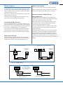
To convert the amplifier to high-voltage line operation, the
low impedance output socket should be unplugged from
CON8 on the main pcb (a short pair of heavy red and black
wires), and replaced by the spare plug connected to the
toroidal transformer nearer the rear of the unit (same wire
types).
Note that the low-impedance output will no longer be
available once the transformer is plugged in. The secondary
(output side) of the transformer is permanently wired to the
line output connector (a 4-pin 5 mm-pitch screw terminal
type), thus the high-voltage output will be active once the
internal connector change has been made. A safety cover is
fitted over the connector, which may be removed to connect
the speaker cable. Replace the cover after the connection
has been made.
The transformer secondary has 3 line outputs: 100 V, 70 V
and 25 V; whilst these have a common 0 V connection, the
output is fully floating i.e. it is isolated from the rest of the
amplifier. When the transformer is in use the maximum total
combined load should not exceed the rated power for the
amplifier model (see table above).
MPA Series User Manual v1.1
9