1
TECHNICAL
Practice
Practice
TELECOM SOLUTIONS
FOR THE
C-4000
Apartment/Office
Entry Controller
2 1 S T C E N T U RY
July 11, 2014
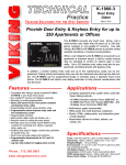
Provide 4 Door Entry Points with Keyless Entry (or
Optional Card Readers) for up to 250 Apartments or Offices
The C-4000 converts any four touch tone phones into
multi-number auto dialers that will store up to 250 telephone numbers in non-volatile memory. Use with
Viking’s K-1700-3 or K-1900-8 phones to provide vandal
resistant handsfree or handset communication from entry
points to apartments or offices.
When a call initiated by the C-4000 is answered by an
apartment or business tenant, a built-in contact closure
may be activated to control an electric gate or door strike.
Up to 250 entry codes may also be programmed providing tenants with keyless entry or optional PRX-1 Card
Readers may be added for proximity card entry.
The C-4000 can be programmed locally or remotely using a standard Touch Tone phone. The
C-4000 has built-in user dialing restriction to help prevent unauthorized calls and toll fraud.
Features
Applications
•
•
•
•
•
• Complete entry system to service 4 entry points
when used with these Viking products:
•
•
•
•
•
•
•
•
•
RS-232 Port for programming via a PC
Remote or local Touch Tone programmable
Supports 4 entry points
Supports 4 Wiegand type card readers
Compatible with Viking’s vandal resistant
K-1700-3, K-1900-8 or any Touch Tone phone
Non-volatile memory (no batteries required)
Stores 250 tenant Touch Tone phone numbers
and 250 entry codes
Programmable tenant’s relay activation code
Programmable Master entry code & Maintenance
Personnel entry codes
Programmable call timer
Normally open and normally closed relay
contacts for controlling door strikes, magnetic
locks, gates, etc.
Touch Tone toll restriction
Allows 911 and 311 outside calls (Programmable)
LOG BUS data output for logging entry events
Phone...715.386.8861
[email protected]
h t t p : / / w w w. v i k i n g e l e c t r o n i c s . c o m
-
K-1700-3 Handsfree Speaker Phone (DOD# 157) OR
K-1900-8 Wall Phone with Handset (DOD# 362) AND
D-Series Tenant Directories (DOD# 158) AND
PRX-1 Proximity Card Reader (DOD# 221) OR
PRX-2 Keypad / Proximity Card Reader (DOD# 219) OR
PRX-3 Proximity Card Reader (DOD# 228) OR
PRX-4 Wiegand Keypad (DOD# 199)
• Multi-tenant, gated communities
• Office parks and multi-business complexes
Specifications
Power: 120V AC/13.8V AC 1.25A, UL listed adapter provided
Dimensions: 210mm x 159mm x 45mm (8.25" x 6.25" x 1.75")
Shipping weight: 1.5kg (3.2 lbs)
Environmental: 0° C to 32° C (32° F to 90° F) with 5% to 95%
non-condensing humidity
Talk Battery Output: 32V DC nominal
DTMF dialing speed: 120ms on/100ms off
Relay contact ratings: 5 Amps @ 30V DC/250V AC
Maximum Wiegand Run: PRX-1: 305m (1000 ft), PRX-2: 91m
(300 ft), PRX-3 (using 3 pairs for power): 305m (1000 ft), PRX-4:
610m (2000 ft)
Maximum LOG BUS Run: 1610m (5280 ft, 1 mile), 24 AWG wire
Connections: (40) cage clamp screw terminals
Wa r r a n t y
IF YOU HAVE A PROBLEM WITH A VIKING PRODUCT, PLEASE CONTACT: VIKING TECHNICAL SUPPORT AT (715) 386-8666
Our Technical Support Department is available for assistance Monday 8am - 4pm and Tuesday through Friday 8am - 5pm central time. So that we can give you better service, before you call please:
1. Know the model number, the serial number and what software version you have (see serial label).
2. Have your Technical Practice in front of you.
3. It is best if you are on site.
RETURNING PRODUCT FOR REPAIR
RETURNING PRODUCT FOR EXCHANGE
The following procedure is for equipment that needs repair:
1. Customer must contact Viking's Technical Support Department at 715-386-8666 to obtain a Return Authorization (RA)
number. The customer MUST have a complete description of the problem, with all pertinent information regarding the
defect, such as options set, conditions, symptoms, methods to duplicate problem, frequency of failure, etc.
2. Packing: Return equipment in original box or in proper packing so that damage will not occur while in transit. Static
sensitive equipment such as a circuit board should be in an anti-static bag, sandwiched between foam and individually boxed. All equipment should be wrapped to avoid packing material lodging in or sticking to the equipment. Include
ALL parts of the equipment. C.O.D. or freight collect shipments cannot be accepted. Ship cartons prepaid to:
Viking Electronics, 1531 Industrial Street, Hudson, WI 54016
3. Return shipping address: Be sure to include your return shipping address inside the box. We cannot ship to a PO Box.
4. RA number on carton: In large printing, write the R.A. number on the outside of each carton being returned.
The following procedure is for equipment that has failed out-of-box (within 10 days of purchase):
1. Customer must contact Viking’s Technical Support at 715-386-8666 to determine possible causes for the problem. The
customer MUST be able to step through recommended tests for diagnosis.
2. If the Technical Support Product Specialist determines that the equipment is defective based on the customer's input
and troubleshooting, a Return Authorization (R.A.) number will be issued. This number is valid for fourteen (14)
calendar days from the date of issue.
3. After obtaining the R.A. number, return the approved equipment to your distributor, referencing the R.A. number. Your
distributor will then replace the product over the counter at no charge. The distributor will then return the product to
Viking using the same R.A. number.
4. The distributor will NOT exchange this product without first obtaining the R.A. number from you. If you haven't
followed the steps listed in 1, 2 and 3, be aware that you will have to pay a restocking charge.
WARRANTY
Viking warrants its products to be free from defects in the workmanship or materials, under normal use and service, for a period of one year from the date of purchase from any authorized Viking distributor or 18 months from the date manufactured, which ever is greater. If at any time during the warranty period, the product is deemed defective or malfunctions, return the product to Viking Electronics, Inc., 1531 Industrial Street, Hudson, WI., 54016. Customer must contact Viking's
Technical Support Department at 715-386-8666 to obtain a Return Authorization (R.A.) number.
This warranty does not cover any damage to the product due to lightning, over voltage, under voltage, accident, misuse, abuse, negligence or any damage caused by use of the product by the purchaser or others.
Vikings sole responsibility shall be to repair or replace (at Viking's option) the material within the terms stated above. VIKING SHALL NOT BE LIABLE FOR ANY LOSS OR DAMAGE OF ANY KIND INCLUDING INCIDENTAL OR CONSEQUENTIAL DAMAGES RESULTING DIRECTLY OR INDIRECTLY FROM ANY BREACH OF ANY WARRANTY EXPRESSED OR IMPLIED, OR FOR ANY OTHER FAILURE OF THIS PRODUCT. Some states do not allow the exclusion or limitation of incidental or consequential damages, so this limitation may not apply to you.
THIS WARRANTY IS IN LIEU OF ALL OTHER WARRANTIES, EXPRESSED OR IMPLIED, INCLUDING THE WARRANTIES OF MERCHANTABILITY AND FITNESS FOR A PARTICULAR PURPOSE, WHICH ARE HEREBY EXCLUDED
BEYOND THE ONE YEAR DURATION OF THIS WARRANTY. Some states do not allow limitation on how long an implied warranty lasts, so the above limitation may not apply to you.
FCC REQUIREMENTS
This equipment complies with Part 68 of the FCC rules and the requirements adopted by the ACTA. On the side of this
equipment is a label that contains, among other information, a product identifier in the format US:AAAEQ##TXXXX. If
requested, this number must be provided to the telephone company.
The REN is used to determine the number of devices that may be connected to a telephone line. Excessive REN's on a
telephone line may result in the devices not ringing in response to an incoming call. In most but not all areas, the sum of
the REN's should not exceed five (5.0) To be certain of the number of devices that may be connected to a line, as determined by the total REN's, contact the local telephone company. For products approved after July 23, 2001, the REN for
this product is part of the product identifier that has the format US:AAAEQ##TXXXX. The digits represented by ## are the
REN without a decimal point (e.g., 03 is a REN of 0.3). For earlier products, the REN is separately shown on the label.
The plug used to connect this equipment to the premises wiring and telephone network must comply with the applicable
FCC Part 68 rules and requirements adopted by the ACTA. If your home has specially wired alarm equipment connected
to the telephone line, ensure the installation of this C-4000 does not disable your alarm equipment. If you have questions
about what will disable alarm equipment, consult your telephone company or a qualified installer.
If the C-4000 causes harm to the telephone network, the telephone company will notify you in advance that temporary discontinuance of service may be required. But if advance notice isn't practical, the telephone company will notify the customer as soon as possible. Also, you will be advised of your right to file a complaint with the FCC if you believe it is necessary.
The telephone company may make changes in its facilities, equipment, operations, or procedures that could affect the
operation of the equipment. If this happens, the telephone company will provide advance notice in order for you to make
the necessary modifications to maintain uninterrupted service.
If trouble is experienced with the C-4000, for repair or warranty information, please contact:
Viking Electronics, Inc., 1531 Industrial Street, Hudson, WI 54016 (715) 386-8666
If the equipment is causing harm to the telephone network, the telephone company may request that you disconnect the
equipment until the problem is resolved.
Connection to Party Line Service is subject to State Tariffs. Contact the state public utility commission, public service commission or corporation commission for information.
WHEN PROGRAMMING EMERGENCY NUMBERS AND (OR) MAKING TEST CALLS TO EMERGENCY NUMBERS:
Remain on the line and briefly explain to the dispatcher the reason for the call. Perform such activities in the off-peak
hours, such as early morning or late evenings.
It is recommended that the customer install an AC surge arrester in the AC outlet to which this device is connected. This
is to avoid damaging the equipment caused by local lightning strikes and other electrical surges.
PART 15 LIMITATIONS
This equipment has been tested and found to comply with the limits for a Class A digital device, pursuant to Part
15 of the FCC Rules. These limits are designed to provide reasonable protection against harmful interference
when the equipment is operated in a commercial environment. This equipment generates, uses, and can radiate radio frequency energy and, if not installed and used in accordance with the instruction manual, may cause
harmful interference to radio communications. Operation of this equipment in a residential area is likely to cause
harmful interference in which case the user will be required to correct the interference at his own expense.
Definitions
26 Bit Wiegand Format: The industry standard data output of access control card readers.
Directory: A posting of tenant’s names and what number to dial for visitors who wish to request access.
Entry Code: The number that when it matches either a Keyless Entry, or a Proximity Card number, allows access. Each
Tenant may have their own unique Entry Code that is easily changed or removed when a tenant moves out.
Entry Point: A door or gate allowing access into a secure or controlled area.
Facility Code: A 3-digit number that each proximity card contains in order to provide greater security. Usually the cards
used at a given building all have the same facility code. By programming cards with different facility codes, these cards can
have access to certain doors. Using this feature, the entry system can be set up for “zones”.
Keyless Entry: A way for tenants to let themselves in, by entering a 4-6 digit Touch Tone Entry Code on any one of four
entry phones.
2
LOG BUS: A two wire data bus. Data is sent as 1200 baud ASCII characters at TTL levels (0-5 Volt). Any RS-232 port
designed to receive TTL levels can receive log bus data directly on the “Receive Data” and “Signal Ground” pins.
Memory Location: The number used when programming that stores the location of a tenant’s phone number and entry
code. This is also the tenant’s number, which would appear on a directory, that a visitor would dial to call a tenant.
Proximity Card: A credit size card that identifies itself when within close proximity of a reader. Card “swiping” is not necessary. The card contains a 3 digit Facility Code, a 5 digit Internal Card number and a 5 digit External Printed number, that
may or may not match the Internal number.
Proximity Card Reader: A device used to read the data from a Proximity Card when it’s held within a few inches of the
reader.
Relay Activation Code: The one or two digit Touch Tone code a tenant enters on their phone to allow a visitor access.
Tenant’s Phone Number: Since the C-4000 uses a phone line to call tenants through the public telephone network, the
tenant’s actual phone number is programmed into the C-4000.
Features Overview
VIKING ©
MODEL C-4000
VIKING
ELECTRONICS
HUDSON, WI 54016
Door Strike Relays
Control up to 4 doorstrikes
or magnetic locks with
Normally Open or Normally
Closed relays. Door strike 1
is controlled from entry
phone 1 and REX 1. Door
strike 2 is controlled from
entry phone 2 and REX 2.
The same goes for door
strike 3 and door strike 4.
APARTMENT OR OFFICE
ENTRY CONTROLLER
POWER
13.8 VAC
Wiegand Inputs
Allows proximity card
readers for each of
the 4 entry points.
DOOR STRIKE RELAYS
PROGRAM
PHONE
WIEGAND INPUTS
LED1
C
PROGRAM
PHONE
N.O. COM N.C. N.O. COM N.C. N.O. COM N.C. N.O. COM N.C. BLK RED GRN WHT BLK RED GRN WHT BLK RED GRN WHT BLK RED GRN WHT
DOOR STRIKE 1 DOOR STRIKE 2 DOOR STRIKE 3 DOOR STRIKE 4
ENTRY 1
ENTRY 2
ENTRY 3
ENTRY 4
RS-232 PORT
C.O. LINE
INPUT
Program Phone - For local
Touch Tone programming.
C.O. / Phone Line Input Used to call up to 250 Tenants.
Auxiliary Line - Use with a
Viking C-3000 to call Tenants that
do not have C.O. phone service.
Entry Phones - Up to 4 entry phones to
service up to 4 entry points. Any analog
phone may be used. Viking's model K-1700-3
and K-1900-8 are recommended.
AUX
LINE
ENTRY
ENTRY
ENTRY
ENTRY
PHONE 1 PHONE 2 PHONE 3 PHONE 4
REX
1
REX
2
REX
3
REX
4
H
L
LOG BUS
RS-232 Port - Connect to a
PC Comm port for optional
PC programming.
LOG BUS - Used to log
entry events on a PC.
REX - Request to exit inputs, used to release a
doorstrike from a push button, motion sensor,
etc. A momentary closure across REX 1 will
activate Door Strike 1. A momentary closure
across REX 2 will activate Door Strike 2. The
same goes for REX 3 and REX 4.
3
Installation
!
IMPORTANT: Electronic devices are susceptible to lightning and power station electrical surges from both the AC
outlet and the telephone line. It is recommended that a surge protector be installed to protect against such surges.
A. Basic Wiring
Note: The diagram below shows only one of up to four possible entry phones, REX buttons, door strikes, and Wiegand
inputs connected.
VIKING ©
120V AC
Viking D-Series Directory
(not included, DOD# 158)
MODEL C-4000
VIKING
ELECTRONICS
HUDSON, WI 54016
13.8V AC
Adapter
Included
APARTMENT OR OFFICE
ENTRY CONTROLLER
POWER
13.8 VAC
DOOR STRIKE RELAYS
PROGRAM
PHONE
Local
Programming
Phone
WIEGAND INPUTS
LED1
C
PROGRAM
PHONE
For Entry Points 2-4, wire
identically to Entry Point 1
as shown below.
N.O. COM N.C. N.O. COM N.C. N.O. COM N.C. N.O. COM N.C. BLK RED GRN WHT BLK RED GRN WHT BLK RED GRN WHT BLK RED GRN WHT
DOOR STRIKE 1 DOOR STRIKE 2 DOOR STRIKE 3 DOOR STRIKE 4
ENTRY 1
ENTRY 2
ENTRY 3
ENTRY 4
RS-232 PORT
C.O. LINE
INPUT
AUX
LINE
ENTRY
ENTRY
ENTRY
ENTRY
PHONE 1 PHONE 2 PHONE 3 PHONE 4
REX
1
REX
2
REX
3
REX
4
H
L
LOG BUS
Entry Point 1
Viking PRX-4
(not included
DOD# 199)
Doorstrike
Power Supply
5A @ 30V DC
maximum
(not included)
* 610m (2000 ft) max
Doorstrike
OR
* 91m (300 ft) max
* 305m (1000 ft) with 3 pair for pwr
OR
C.O. Line or Analog
PABX/KSU Station
* 305m
(1000 ft) max
Viking PRX-2
(not included
DOD# 219)
OR
Optional C-3000 (not included, DOD# 162)
VIKING ©
MODEL C-3000
Optional "Push to Open / Request to Exit"
Button (not included)
VIKING
ELECTRONICS
HUDSON, WI 54016
12 UNIT APARTMENT
ENTRY CONTROLLER MODULE
POWER
13.8 VAC
POSTAL
LOCK
INPUT
DIP
SWITCH
1 2 3
DOOR
STRIKE
1
Viking PRX-3
(not included
DOD# 228)
Viking PRX-1
(not included
DOD# 221)
Analog Entry Phone (not included)
DOOR
STRIKE
2
1 2 3 4 5 6 7
- or -
RJ21X
12 APARTMENT LINES IN/OUT
8
MULTI-MODULE
INTERCONNECT
ENTRY 1
ENTRY 2
OUT
IN
K-1900-8
(DOD# 362)
If some tenants do not have C.O. phone service, the
Viking model C-3000 can be added to ring up to 12
tenant's phones. Up to eight C-3000 units can be
cascaded to support a total of 96 "No C.O." tenants.
K-1700-3
(DOD# 157)
Optional backboxes
available, see DOD# 424.
* Note: Maximum Wiegand run length is 1000 feet using 24 gauge wire when using the Viking model PRX-1 proximity card reader,
300 feet for the PRX-2 card reader/keypad, 1000 feet for the PRX-3 (using 3 wire pairs for power), and 2000 feet for the PRX-4 keypad. Run length is reduced to half if two share the same wire run from the same C-4000 entry point. Run lengths can be doubled by
doubling up on the BLACK and RED 24 gauge wire, or using 21 gauge (or larger) wire. Certain electrically noisy locations might
require shielded wire.
4
B. Optional LOG BUS Wiring
The C-4000 transmits 1200 baud ASCII data from the
LOG BUS screw terminals. Log Bus data is sent each
time there is an entry point event, and includes: an
entry point ID number, if the entry was valid or nonvalid, the facility code, and the card number (or keypad entry code).
VIKING ©
MODEL C-4000
VIKING
ELECTRONICS
HUDSON, WI 54016
APARTMENT OR OFFICE
ENTRY CONTROLLER
POWER
13.8 VAC
DB-9
(not included)
DOOR STRIKE RELAYS
Pin 2
(Receive Data)
Pin 5
(Signal Ground)
PROGRAM
PHONE
WIEGAND INPUTS
LED1
C
PROGRAM
PHONE
N.O. COM N.C. N.O. COM N.C. N.O. COM N.C. N.O. COM N.C. BLK RED GRN WHT BLK RED GRN WHT BLK RED GRN WHT BLK RED GRN WHT
DOOR STRIKE 1 DOOR STRIKE 2 DOOR STRIKE 3 DOOR STRIKE 4
ENTRY 1
ENTRY 2
ENTRY 3
ENTRY 4
RS-232 PORT
C.O. LINE
INPUT
H
Brown (Receive Data)
L
Yellow (Signal Ground)
AUX
LINE
ENTRY
ENTRY
ENTRY
ENTRY
PHONE 1 PHONE 2 PHONE 3 PHONE 4
REX
1
REX
2
REX
3
REX
4
H
L
LOG BUS
1610m (5280 ft - 1 mile) maximum run length using 24 gauge wire
Communication Software Configuration
If the RS-232 input of a PC, printer, etc. is capable of receiving TTL level
RS-232 signals, then the LOG BUS can be wired directly into the RS-232
“Receive Data” and “Signal Ground” pins to receive ASCII data. Windows
“Hyper-Terminal” can be used to receive the data on a PC. Use the settings in the chart at the right:
Com
Your serial port (1-4)
Baud Rate
1200
Data Bits
8
Stop Bits
1
Parity
none
Flow Control
none
C. Optional PC Programming Wiring
Programming the C-4000 can be done with a Touch Tone phone or by using a PC. If using PC programming, use a
serial port connection as shown below and visit www.vikingelectronics.com to download free C-4000 programming
software. Compatible with any Windows based PC running Windows 98 or higher, the software allows programming of
all C-4000 parameters using the computer.
Note: After PC programming is accomplished, it is recommended to not use Touch Tone programming to make
changes, as these changes will not show in the PC programming data base. If Touch Tone programming is used to
make changes, be sure to make those same changes in the PC programming data base to keep it accurate.
VIKING ©
MODEL C-4000
VIKING
ELECTRONICS
HUDSON, WI 54016
APARTMENT OR OFFICE
ENTRY CONTROLLER
POWER
13.8 VAC
* IMPORTANT: Viking Electronics will NOT support computer software or hardware problems. If you experience
these problems, research your hardware/software instruction manuals or contact the manufacturer’s technical support department.
DOOR STRIKE RELAYS
* Personal Computer
PROGRAM
PHONE
WIEGAND INPUTS
LED1
C
PROGRAM
PHONE
N.O. COM N.C. N.O. COM N.C. N.O. COM N.C. N.O. COM N.C. BLK RED GRN WHT BLK RED GRN WHT BLK RED GRN WHT BLK RED GRN WHT
DOOR STRIKE 1 DOOR STRIKE 2 DOOR STRIKE 3 DOOR STRIKE 4
ENTRY 1
ENTRY 2
ENTRY 3
ENTRY 4
RS-232 PORT
C.O. LINE
INPUT
AUX
LINE
ENTRY
ENTRY
ENTRY
ENTRY
PHONE 1 PHONE 2 PHONE 3 PHONE 4
REX
1
REX
2
REX
3
REX
4
H
L
LOG BUS
Standard "Straight Thru"
RS-232 Cable
(included)
5
To u c h To n e P r o g r a m m i n g
Note: While the C-4000 is being programmed, guests are not able to call up to a tenant because the hardware and/or
phone line is unavailable. A busy signal will be given indicating that the system is busy. Tenants can still use keyless entry
codes and card readers for access at any entry point during programming.
A. Accessing the Programming Mode
1. Remote Programming
Step 1. Connect the CO LINE port to a C.O. line or analog PABX/KSU station.
Step 2. From a Touch Tone phone, call the line connected to the C-4000.
Step 3. When the C-4000 answers, enter “Q” followed by the six digit security code, factory set to 845464 (see section B
on the following page). A double beep will indicate that programming has been entered.
Step 4. Program as shown in sections C - K.
Step 5. To exit programming, do NOT enter any Touch Tones for approximately 20 seconds. Three beeps will be heard,
followed by an automatic disconnect.
2. Local Programming
Step 1. Connect a phone to the PROGRAM PHONE jack.
Step 2. Come off hook. A double beep will indicate that programming has been entered. Note: The double beep might be
delayed if a call is in progress.
Step 3. Program as shown in section C - K.
Step 4. To exit programming, simply hang up the phone.
B. Security Code
A six digit number is used to access remote programming. This security code has been factory set to 845464 (V-I-K-I-N-G).
It is recommended that you change the security code to a personal 6 digit number as follows:
Step 1. Access programming as shown in section A.
Step 2. Enter your new security code followed by ##5.
Step 3. To exit remote programming, do NOT enter any Touch Tones for at least 20 seconds.
Note: The security code must be six digits in length and MUST NOT contain a Q or #. If you have forgotten your security
code, see Local Programming in section A.
C. Tenant’s Phone Numbers and Entry Codes
The C-4000 can be programmed with up to 250 tenant phone numbers and up to 250 tenant entry codes, 5 maintenance
personnel entry codes and 1 master entry code. A tenant can activate the door strike, keyless, from the entry phone by dialing a “#” followed by their 4-6 digit entry code, or by using a proximity card with its 5 digit card number programmed as the
entry code. When a given tenant moves out of the complex, the phone number and entry code for that tenant may be cleared
without affecting any other tenant’s phone numbers or entry codes. Note: The entry codes should all be the same number
of digits, either 4, 5 or 6. If using Wiegand devices (PRX-1, PRX-2, PRX-3 or PRX-4), entry codes must be 5 digits in length.
An entry code may be programmed without a phone number.
WARNING: If using a Viking model PRX-4 keypad, do not program the C-4000 to accept entry code 65535, because this
number is the PRX-4’s error code.
IMPORTANT: 26-bit Wiegand data limits the entry code range from 00001 to 65534, when using Wiegand devices such as
the PRX-1, PRX-3, PRX-4, etc.
1. Programming a Phone Number Only
While in programming, enter the tenant’s phone number + “#” + memory location number (001 - 250).
Example: 5551212 # 001
2. Programming a Phone Number and Entry Code
Note: If a phone number and an entry code are to be programmed into a memory location (001-250), they must be programmed together.
While in programming, enter the tenant’s phone number + “#Q” + the entry code for the tenant (4-6 digits) + “#” + memory location number (001 - 250). Example: 5551212 #Q 123456 # 001
3. Programming an Entry Code Without a Phone Number
6
You are allowed to program an entry code in a memory location without programming a phone number. The memory
location then becomes dedicated to entry code storage. This is programmed by entering “#Q” + the entry code (4 - 6
digits) + “#” + the memory location (001 - 250). Example: #Q 123456 # 001
4. Adding a Master Entry Code
The master entry code is simply an additional entry code in memory position 000. If keyless entry is disabled (when card
readers are used), this master entry code will still function as a keyless code. This is programmed by entering “#Q” +
the master entry code (4 - 6 digits) + “#” + the memory location 000.
Example: #Q 123456 # 000
5. Adding Maintenance Personnel Entry Codes
The maintenance personnel entry codes are simply an additional 5 keyless entry codes in memory locations 251-255.
This is useful when you require additional entry codes for a non-tenant (guard, maintenance worker, etc.) If keyless entry
is disabled (when card readers are used) these entry codes will still function as a keyless code. This is programmed by
entering “#Q” + the entry code (4 - 6 digits) + “#” + the memory locations 251-255. Example: #Q 123456 # 251
6. Deleting the Phone Number and Entry Code for One Memory Location
While in programming dial a “#” + memory location (000 - 255) to clear.
Note: It is not possible to erase only the phone number or the keyless entry number. If either number needs to
be changed, BOTH numbers must be reprogrammed.
7. Deleting All Phone Numbers and Entry Codes
While in programming, enter “###”. This will clear all phone numbers, entry codes and set all programming back
to factory settings.
! CAUTION: All phone numbers and entry codes will be permanently erased.
D. Programming Features Quick Reference
Features
Tenant’s phone numbers: 001-002 (0-32 digits), 003-250 (0-16 digits) .....................
Tenant’s phone numbers and entry codes ................................................................
To add a Q at any point in the dialing string ............................................................
To add a # at any point in the dialing string ..............................................................
Entry code only (4-6 digits) .......................................................................................
Master entry code (4 - 6 digits) .................................................................................
Maintenance personnel entry codes (4-6 digits) .......................................................
Clear one phone number and entry code .................................................................
PABX line access number: 1-3 digits + 3 sec pause (factory disabled) .....................
Entry point 1 relay activation time (.5-99 sec, 00=.5 sec, factory set to 5 sec) ..........
Entry point 2 relay activation time (.5-99 sec, 00=.5 sec, factory set to 5 sec) ..........
Entry point 3 relay activation time (.5-99 sec, 00=.5 sec, factory set to 5 sec) ..........
Entry point 4 relay activation time (.5-99 sec, 00=.5 sec, factory set to 5 sec) ..........
* Relay activation code: one or two digits (factory set to 36) .....................................
Security code (factory set to 845464) .......................................................................
Maximum call time : 0-99 sec (00=disabled, factory set to 40 sec) ...........................
Disable tenant keyless entry ....................................................................................
Enable tenant keyless entry (factory setting) .........................................................
Disable ring-thru mode (factory setting) ..................................................................
Enable ring-thru mode ..............................................................................................
Enable 911 and 311 calling from entrance phones (factory setting) ........................
Disable 911 and 311 calling from entrance phones ..................................................
1 second pause anywhere in the dialing string ........................................................
Access auxiliary line .................................................................................................
Clear all phone numbers and keyless entry codes from memory and
set all programming features back to factory settings ...............................................
Enter Digits
- then -
Memory
Location
phone number
+
#001-250
phone number + #Q + entry code + #001-250
QQ
Q#
#Q + entry code
#Q + entry code
#Q + entry code
(no digits)
1-3 digit
2 digits (00 - 99)
2 digits (00 - 99)
2 digits (00 - 99)
2 digits (00 - 99)
1 or 2 digits (0 - 99)
6 digits (no # or Q)
2 digits (00 - 99)
Q1
Q2
Q3
Q4
Q5
Q6
Q8
Q9
+
+
+
+
+
+
+
+
+
+
+
+
#001-250
#000
#251-255
#001-255
##2
##31
##32
##33
##34
##4
##5
##6
### (CAUTION: Erases ALL programming!)
* The relay may be activated with a single digit. When a single digit (0-9) relay activation code is programmed, the activation Touch
Tone must be held for a minimum of 150 milliseconds.
Notes: Each pause uses a single digit. To clear a memory location, enter only the location (no digits). A valid programming entry
will be indicated by a double beep. An invalid entry will be indicated with three beeps.
7
E. Programming Examples
These examples would be entered after accessing programming as shown in section A.
Programming the C-4000...
Enter Digits
1. ...to dial 555-1234 when a “1” is entered at the entrance phone
5551234 #001
2. ...to dial a 9 and pause 3 seconds prior to dialing all numbers
9 ##2
3. ...to activate the door strike/magnetic lock when the tenant dials a “6”
6 ##4
4. ...to set entry code for tenant 3 to “9876” with phone number 555-1234
5551234#Q9876 #003
5. ...to set an entry code for tenant 4 to “9876” without a phone number
#Q9876 #004
6. ...to delete the entry code and phone number for tenant 5
#005
7. ...to set a maximum call time of 20 seconds
20 ##6
8. ...to set the master entry code to “123456”
#Q123456 #000
9. ...to call position 1 of a C-3000 (aux. line) when 1 is dialed at entry phone
Q901
#001
F. Programmable Maximum Call Time
The C-4000 can be programmed to limit the call time on the entry phone. The maximum call time is programmable
from “00” (no maximum call time) to “99” (99 seconds and is factory set to “40” (40 seconds) (see Programming, section D). When the call timer is enabled (programmed to “01-99”), if a call exceeds the programmed time, both phones
are provided with three beeps, indicating the termination of the call, then disconnected. This limits unnecessary and
lengthy conversations, and limits the chances that a second entry phone gets a busy signal. When the call timer is
disabled (programmed to “00”), there is no limit to the length of calls from the entry phone. Only a CPC disconnect
signal from the telephone line, or hanging up the entry phone will disconnect the call.
G. Built-In Toll Restriction
The C-4000 features built-in toll restriction. The unit will disconnect when it detects any Touch Tone generated by the
entry phone, after speed dialing has been completed.
H. Card Readers / Wiegand Keypads
One or two Wiegand type card readers or keypads can be added to each of the four C-4000 entry points for card
access control. Notes: If neither visitor access nor keyless entry are required, a Viking model PRX-1 Card Reader is
all that is needed and an entry phone is not required. If visitor access is not required, but keyless entry is required, a
Viking model PRX-4 Keypad is all that is needed and an entry phone is not required. Twenty-six bit Wiegand access
cards, such as the Viking PRX-C, PRX-C-ISO, PRX-FOB and certain legacy HID® proximity protocols*, identify themselves with an 8-digit number. The first 3 digits are considered the Facility Code and the last 5 are the card number.
The C-4000 shares the entry code memory location for both keyless entry and card entry. In other words, the 5-digit
card number or keypad entry, is to be programmed as the tenant’s entry code if used. Unless facility codes are programmed, the C-4000 will only need to match the 5-digit card number with any programmed entry code to allow
access. For a higher level of security the access card’s 3-digit Facility Code should be programmed in addition to the
card number. The facility codes are to be programmed per each of the four entry points of the C-4000.
Each entry point can be programmed to accept up to 4 different Facility Codes. In this way, different groups of users
can be issued access cards with different Facility Codes to create entry points in which some groups are allowed
access, and/or other groups are not. This open form of creating “Zones” means each entry point can be its own unique
zone.
Note: If all 4 Facility Code locations are programmed to “000” (factory setting), the C-4000 will disregard the Facility
Code all together, thus making access entry based only on the card number match with the programmed entry code.
Important: 26 Bit Wiegand data limits the facility code range from 001 to 255. A facility code larger than 255 will not
be accepted.
When in programming, enter the 3-digit Facility Code of the access cards being used, then “#” and the memory locations as shown below. (Example: 123#911)
Memory
Programming Facility Codes
Enter Digits - then Location
Facility codes for entry point 1 ................................................................................................ 3
Facility codes for entry point 2 ................................................................................................ 3
Facility codes for entry point 3 ................................................................................................ 3
Facility codes for entry point 4 ................................................................................................ 3
8
digits
digits
digits
digits
+
+
+
+
#911-914
#921-924
#931-934
#941-944
* HID and the HID logo are registered trademarks of HID Global Corporation, an ASSA ABLOY company. All other trademarks are the property of
their respective owners.
I. Disable Keyless Entry
By using Proximity cards instead of keyless entry, the building manager keeps control over the number of people that
can let themselves into the building. If the card numbers are printed on the cards, tenants will quickly figure out the 5digit printed card number also works as a keyless entry code. Disabling the ability to use keyless entry is therefore
recommended when card readers are used. Note: If keyless entry needs to be used in addition to proximity card readers, be sure to order cards with the printed number “offset” from the actual card number. This way only the security
manager that knows the offset value can decode it.
While in programming, enter “Q1” to disable keyless entry, or “Q2” to enable keyless entry. Note: When disabled, the
master and maintenance personnel entry codes still function as keyless entry.
J. Ring-Thru Mode
Inbound calls are normally answered by the C-4000 so that remote programming is possible. If the ring-thru mode is
selected, inbound calls are allowed to ring through to Entry Phone 1. While in programming, enter “Q4” to enable ringthru mode or “Q3” to disable ring-thru mode.
K. Using the “AUX” Line
The C-4000 normally dials the tenant’s phone number from the “C.O.” connections, but can be programmed to dial out
the “AUX” screw terminals. This is needed when integrating some tenants that don’t have C.O. phone service and
Viking C-3000s are added. When programming a tenant’s phone number, add “Q9” as the first 2-digits of the phone
number (or enter a “C” ahead of the phone number if programming from a PC) to have the C-4000 call out on the “AUX”
line.
Operation
A. Visitor Access Control
When a visitor accesses an entry phone, simulated dial tone is heard. After the visitor enters the appropriate one to
three digit tenant number (equal to memory locations 001-250 in programming), the C-4000 dials the tenant’s phone
number and bridges the phone line to the entry phone. If an un-programmed tenant number (memory location) is
entered, a fast busy signal will be heard on the entry phone. When the tenant confirms the visitors identity, a one or
two digit relay activation code may be entered from the tenant’s phone (factory setting is “36”). Two beeps will indicate
that a valid activation code has been entered. A buzzing sound is then heard on the entry phone to indicate the door
strike has been activated. If the visitor presses a Touch Tone or an incorrect relay activation code is entered, the unit
will disconnect. A fast busy signal will also be returned to the entry phone if the telephone line has become disconnected. The C-4000 can only make one call at a time. If a second phone comes off-hook while another entry phone is
in use, it will be given a fast busy signal. Note: To avoid busy signals on the entry phones, call waiting is recommended on each tenant’s phone line.
Tenants that do not have C.O. telephone line service can be called through the Viking C-3000 when wired to the “AUX”
screw terminals of the C-4000. Each C-3000 supports up to 12 tenants and up to 8 C-3000’s can be added to support
a total of 96 “No C.O.” tenants. If the C-4000 is installed at a business where a PABX is used, the C-4000 can be
installed on a station of the PABX and be programmed to dial extension numbers on the PABX and/or dial 9 to place
outbound C.O. calls.
B. Tenant Keyless Entry
Each tenant may use their personal entry code to let themselves in by taking an entry phone off-hook and enter a “#”
followed by their 4-6 digit personal entry code. Similar to visitor access above, if a second entry phone comes off-hook
while another entry phone is in use, it will be given a fast busy signal. Dial tone will be available when the first call is
complete. A valid keyless entry code will activate the door strike relay. If the ability to use tenant keyless entry codes
is disabled because proximity card readers are used (see Programming section I), the master entry code and maintenance personnel entry codes will still remain functional as keyless entry.
C. Tenant Card Reader Entry
An optional Wiegand device, such as the Viking PRX-1 or PRX-3 Proximity Card Reader, is fully supported (power and
data) for each of the four entry points. The C-4000 entry controller monitors the Wiegand devices for 26 bit Wiegand
data. When a card is read, the data is compared against Facility Code and Entry Code data bases of the C-4000, and
access is granted if a match is found.
9
D. Ring-Thru Mode
If the Ring-Thru mode is selected (see Programming section J), incoming calls are allowed to ring through the C-4000
to Entry Phone 1. If that door phone has an auto-answer feature, this will allow the user to “monitor” that entry way.
The C-4000 is still watching for the security code and will seize the line if a valid code is detected. In this manner, the
C-4000 may still be remotely programmed. In this mode the relay activation code may also be used to buzz in approaching guests. If the Ring-Thru mode is turned off, the C-4000 will answer all inbound calls and watch for the security code
for remote programming. Note: To utilize the Ring-Thru mode with a K-1700-3 entry phone, DIP switch 5 on the K-17003 must be in the ON position (Fax Back Document 157).
E. AUX Line
Any tenant phone number that is programmed with a leading “Q9” (or enter a “C” ahead of the phone number if programming from a PC) will be dialed out the ”AUX“ screw terminal connections instead of the “C.O.” connections. The
ability to dial out on one of two lines provides additional flexibility to some unusual installations. For example: Some tenants do not have C.O. phone service, so a Viking C-3000 is used to ring those tenants phones, or some tenants phones
are on PABX extensions, so the “AUX” line can be wired to that PABX for extension dialing. Note: When using a C3000 with the C-4000, the relay activation code in the C-3000 should be “disabled” by accessing the programming
mode of the C-3000 and dialing “##4”.
F. Request to Exit
If a “Push to Open” button, push bar switch, key switch, motion sensor, etc. provides a momentary contact closure to
the Request to Exit screw terminals, the door strike relay will activate. This can be used for a receptionist to allow
entry for visible guests, activate a gate for exiting tenants, provide key access for postal service, etc.
G. Data Logging
Each time there is an entry point event, the C-4000 will transmit 1200 baud ASCII data out of its LOG BUS screw terminals. An example of 5 different entry events is shown below. The C-4000 outputs entry event data in real time, but
does not time stamp.
Simulated LOG BUS Output
Examples:
Valid Card Entry ...........................
Valid Card Entry ...........................
Non-Valid Keyless Attempt .........
Valid Keyless Entry ......................
A guest was granted entry by .....
tenant in memory location 007
1
3
1
2
4
V
V
N
V
V
255
132
KLS
KLS
GST
Entry Point ID Number
12345
06336
8132
708132
007
Card number from Wiegand device or keyless code entered
(keypad) or tenant memory location number if a guest called
If the entry attempt Valid (V)
or Not Valid (N)
Facility Code from Wiegand device or (KLS) for keyless code,
or (GST) if a guest called a tenant
H. Entry Logger Software
Visit www.vikingelectronics.com to download free ENTRY LOGGER software. The software provides transaction logging for the ES-1 and C-4000 Entry Controller systems. Compatible with any Windows based PC running Windows 98
or higher, the software adds time and date stamps to each transaction, and allows user printing, record saving, and
complete search capabilities.
Product Support Line...715.386.8666
Fax Back Line...715.386.4345
Due to the dynamic nature of the product design, the information contained in this document is subject to change without notice. Viking Electronics, and its affiliates and/or
subsidiaries assume no responsibility for errors and omissions contained in this information. Revisions of this document or new editions of it may be issued to incorporate
such changes.
DOD# 164
10
Printed in the U.S.A.
ZF301760 Rev C
Please use these charts to record the numbers programmed into the C-4000 (use pencil).
Security Code:
Memory Location
001
002
003
004
005
006
007
008
009
010
011
012
013
014
015
016
017
018
019
020
021
022
023
024
025
026
027
028
029
030
031
032
033
034
035
036
037
038
039
040
041
042
043
044
045
046
047
048
049
050
051
052
053
054
055
056
057
058
059
060
061
062
063
064
065
066
067
068
069
070
071
072
073
074
075
Relay Activation Code:
Apt #
Tenant’s Phone #
Entry Code #
Memory Location
076
077
078
079
080
081
082
083
084
085
086
087
088
089
090
091
092
093
094
095
096
097
098
099
100
101
102
103
104
105
106
107
108
109
110
111
112
113
114
115
116
117
118
119
120
121
122
123
124
125
126
127
128
129
130
131
132
133
134
135
136
137
138
139
140
141
142
143
144
145
146
147
148
149
150
Apt #
Tenant’s Phone #
Entry Code #
Memory Location
151
152
153
154
155
156
157
158
159
160
161
162
163
164
165
166
167
168
169
170
171
172
173
174
175
176
177
178
179
180
181
182
183
184
185
186
187
188
189
190
191
192
193
194
195
196
197
198
199
200
201
202
203
204
205
206
207
208
209
210
211
212
213
214
215
216
217
218
219
220
221
222
223
224
225
Apt #
Tenant’s Phone #
Entry Code #
Memory Location
Apt #
Tenant’s Phone #
Entry Code #
226
227
228
229
230
231
232
233
234
235
236
237
238
239
240
241
242
243
244
245
246
247
248
249
250
Additional Entry Codes
Memory Location
Description
000
251
252
253
254
255
Master
Maintenance Personnel
Maintenance Personnel
Maintenance Personnel
Maintenance Personnel
Maintenance Personnel
Entry Code #
Access Card Facility Codes
Memory Location
911
912
913
914
Memory Location
921
922
923
924
Memory Location
931
932
933
934
Memory Location
941
942
943
944
Description
Entry
Entry
Entry
Entry
Point
Point
Point
Point
Description
Entry
Entry
Entry
Entry
Point
Point
Point
Point
Point
Point
Point
Point
Point
Point
Point
Point
Facility Code
3
3
3
3
Description
Entry
Entry
Entry
Entry
Facility Code
2
2
2
2
Description
Entry
Entry
Entry
Entry
Facility Code
1
1
1
1
4
4
4
4
Facility Code