1
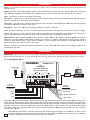
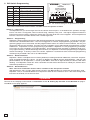
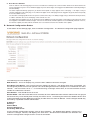
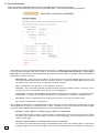
Designed, Manufactured and Supported in the USA
VIKING PRODUCT MANUAL
C O M M U N I C AT I O N & S E C U R I T Y S O L U T I O N S
RC-4
Network Enabled
Relay Controller
October 29, 2013
Control Relay Contacts Across a Local Area Network
The RC-4 Network Enabled Relay Controller provides networked control of four remote relays via
a web interface. The same interface can be used
to check the status of four contact closures at the
remote location.
Relays can be toggled on or off, or user-programmed timed closures can be activated. Two
levels of user access permit selected users to have
full operational and programming rights while others have operational control but not programming
capability.
Features
• Terminal strip connections for normally open,
normally closed, and common for all four relays
• Relays can be toggled or timed closures of
from 1 - 99 seconds can be activated
• Terminal strip connections for all four sensor inputs
• Notification by email or text message of
sensor input state change (available in first
quarter of 2014)
• Ready-to-use webpage control interface
• Encrypted login
• Two levels of access based on login:
- Administrator (full access)
- Guest (programmable limits)
• Relay names and input names can be customized on webpage
• Firmware remotely updateable
www.vikingelectronics.com
Information: (715) 386-8861
Applications
Remote Control of:
•
•
•
•
•
•
•
Secure building entry
Heating/cooling equipment
Pumps and fans
Security system
Gates
Lighting
Emergency tones
Specifications
Power: 120VAC/12VDC 500ma UL listed adapter
provided
Dimensions: 133mm x 89mm x 44mm (5.25” x
3.5” x 1.75”)
Shipping Weight: .9 kg (2 lbs)
Environmental: 0 C to 32 C (32 F to 90 F) with
5% to 95% non-condensing humidity
Relay Contact Ratings: 5A @ 30VDC/250VAC
Connections: (1) 12 position screw terminal
block, (1) 6 position elevated screw terminal block
LAN Interface: (1) RJ45 10Base-T
Minimum Requirements: Windows XP and
newer, Mac OSX or newer, Android 2.2 or newer,
iOS4 or newer (iPhone requires chrome), Javascript enabled internet browser
Definitions
Client: A computer or device that makes use of a server. As an example, the client might request a particular file
from the server.
DHCP: Dynamic Host Configuration Protocol. In this procedure the network server or router takes note of a client’s
MAC address and assigns an IP address to allow the client to communicate with other devices on the network.
Host: A computer or device connected to a network.
Host Name: A host name is a label assigned to a device connected to a computer network that is used to identify the
device in various forms of network communication.
Hosts File: A file stored in a computer that lists host names and their corresponding IP addresses with the purpose
of mapping addresses to hosts or vice versa.
IP Address: This is the address that uniquely identifies a host on a network.
LAN: Local Area Network. A LAN is a network connecting computers and other devices within an office or building.
Lease: The amount of time a DHCP server reserves an address it has assigned. If the address isn’t used by the
host for a period of time, the lease can expire and the address can be assigned to another host.
MAC Address: MAC stands for Media Access Control. A MAC address, also called a hardware address or physical
address, is a unique address assigned to a device at the factory. It resides in the device’s memory and is used by
routers to send network traffic to the correct IP address. You can find the MAC address of your RC-4 printed on a
white label on the top surface of one of the relays.
Server: A computer or device that fulfills requests from a client. This could involve the server sending a particular file
requested by the client.
Installation
IMPORTANT: Electronic devices are susceptible to lightning and power station electrical surges from both the AC
outlet and the telephone line. It is recommended that a surge protector be installed to protect against such surges.
A. Installing the RC-4
VIKING ©
MODEL RC-4
12V DC Adapter
(included)
POWER 12V DC
VIKING
ELECTRONICS
HUDSON, WI 54016
PC
NETWORK ENABLED
RELAY CONTROLLER
STATUS
LED
RELAY 1
1
2
3
RELAY 2
4
5
6
2
3 4 5 6
1
IN1 C IN2 IN3 C IN4
RELAY 3
7
8
RELAY 4
LOGIC LEVEL
PROGRAMMING
RESTORE DEFAULTS
SPARE
9 10 11 12
1234
Server
NETWORK
LED 9
LED 4
LED 5
LED 6
LED 7
LED 1
LED 2
LED 3
LED 8
Relay
Examples:
Doorstrike
Gate
Light
Fan
on
1
2
3
4
Sensor
Examples:
Temperature Sensor
Door Sensor
Liquid Level Sensor
Light Sensor
Hook up the RC-4 as shown above. The relay outputs can be connected to devices that are controlled by contact closures, such as doorstrikes or gates. Both normally open and normally closed terminals are provided. The sensor terminals are to be connected to devices that indicate their state by either opening or closing a contact. Examples would
include a maximum or minimum temperature sensor or a door sensor. When all the relay and sensor connections
have been made, use a network cable to connect the network jack on the RC-4 to a network jack on your LAN. Plug
in power to the RC-4.
2
When RC-4 is powered up, it sends a request to the network server to assign it an IP address. If there are addresses available, the server assigns one and relays this information to the RC-4. From this point on, this address
is used by the RC-4 to communicate with the rest of the network.
B. Setting Up the RC-4 on the Network
The RC-4 is controlled by a webpage that is accessed using a web browser. To connect to the page, it is necessary
to know either the IP address of the RC-4, which is the address that was assigned by the network server when
the RC-4 powered up, or to know the host name of the RC-4. Once you are able to connect to the RC-4, it can
be operated using the dynamic IP address assigned by the server or it can be programmed to use a static IP address.
1. Unit Name (Host Name) (Windows only)
When the RC-4 is accessed using a browser, it is acting as a host. Most networks allow the user to address
the host using the host name, which is a sort of nickname that can be used instead of typing in the full fourbyte IP address of the host. The default host name of the RC-4 is “myviking”. Type http://myviking into the
address bar of the browser and hit enter or click on the arrow. If the Viking RC-4 access page comes up, proceed to 4. Authentication.
If entering the host name produces a “cannot display the webpage” message, the network server was unable
to translate the host name into an IP address. From this point, there are two ways to proceed. Both require
finding out what IP address the network server assigned to the RC-4.
2. Dynamic IP Address (Windows and Mac OSX)
When the RC-4 is connected to a network server and powered up, it receives an IP address from the network
server. This address can be determined by using the Microchip TCPIP Discoverer, which reads and displays
it. The utility can be downloaded from Viking’s website:
http://www.vikingelectronics.com/downloadx/rc-4ethernet.php
Under Quick Links at the middle right of the home page, find Software Downloads and click on it. You can read
the information and then scroll down to the bottom of the page and click on “I Accept”. Find “Microchip TCPIP
Discoverer” in the list of selections, click on it and proceed with the download.
The Android version of this app is freely available in the Google Market. Search for “Viking Electronics” and
download “RC-4 Discoverer.” Wi-fi is required, finds local units only.
Once the discoverer has been downloaded, double-click on the icon to activate it. In the display that comes
up, look for the line that has the host name “myviking”. Just to the left of this entry is the IP address that has
been associated with the RC-4. Type this into the browser’s address bar and click to bring up the RC-4 webpage. Note that from this point on the page can be accessed by clicking on this address in the browser history
instead of manually entering it every time, as long as browser history is not cleared. Another way of setting up
the first connection is to just double-click on the line in the discoverer display where the RC-4 is shown. While
this also connects to the webpage, it does not store the page in browser history, so it should be stored in favorites for future fast access.
If you have tried the steps above and are still not connected, see the last section, Troubleshooting.
3. Static IP Address
To set the RC-4 up for operation with a static IP address, first arrange with your network administrator for an
address on the server to be configured as a static IP address. Once this is done, use the default host name
“rc4host” or the dynamic IP address obtained on powerup to connect to the RC-4 (see sections 1 and/or 2
above). Click on “Settings” at the bottom left of the main page, and at the bottom of the Settings page, click
on “Network Configuration”. Find the Enable DHCP checkbox near the bottom and uncheck it. The text boxes
below are no longer greyed out. In the IP Address box, enter the static IP address you want to use. The Gateway, Subnet Mask, Primary and Secondary DNS server boxes can be left unchanged. After making this
change, it will likely be necessary to clear the hostname cache in order to connect with the new IP address.
This can be done by entering “nbtstat –R” in the Windows command prompt window.
4. Authentication
The RC-4 is securely accessed using the Digest Authentication procedure. There are two levels of access,
each requiring the entry of a user name and password. The Guest level allows operation of the relays but not
programming of their default closure times or changes to username and password or network configuration.
The Administrator level allows both relay operation and programming (see Programming sections A and B).
The default usernames and passwords are listed below.
Guest username: guest
Guest password: password
Admin username: admin
Admin password: viking
There is one guest username and password available, and one admin username and password. It is recommended that these be changed to unique values for better security. If you forget your username and password,
see C. DIP Switch Programming, Switch 3 to return to the original factory settings and reprogram the usernames and passwords.
3
VIKING ©
C. DIP Switch Programming
MODEL RC-4
VIKING
ELECTRONICS
HUDSON, WI 54016
1
OFF
Logic Level 15V with a 7V trip point
1
ON
Logic Level 5V with a 2.5V trip point
2
OFF
Programming access is enabled
2
ON
Programming access is blocked
3
OFF
Normal operation
3
ON
Restore factory programming defaults
4*
OFF
Normal email notification
4*
ON
10 second email debounce
POWER 12V DC
Switch Position Description
NETWORK ENABLED
RELAY CONTROLLER
STATUS
LED
RELAY 1
1
2
3
RELAY 2
4
5
6
2
3 4 5 6
1
IN1 C IN2 IN3 C IN4
RELAY 3
7
8
RELAY 4
LOGIC LEVEL
PROGRAMMING
RESTORE DEFAULTS
SPARE
9 10 11 12
1234
LED 9
LED 4
LED 5
LED 6
LED 7
LED 1
LED 2
NETWORK
on
LED 3
LED 8
on
1
2
3
4
1
2
3
4
Note: The default setting for all dipswitches is OFF.
* The email notification feature will be available in the first quarter of 2014.
Switch 1 – Logic Level
This dipswitch lets you set the logic level for the contact closure inputs. In the default OFF position, the logic
level is 15V with a 7V trip point, which is best for long, relatively noisy runs. The higher trip point makes the
input more immune to noise. Closing the switch sets a 5V logic level with a 2.5V trip point. This is the preferred
level for a short run to another device with a similar logic level.
Switch 2 – Programming
Dipswitch 2 allows programming on the Set Defaults and Network Configuration pages. It works in conjunction
with the user’s authentication level. If the user is logged in as a Guest, no programming is possible. The programming pages can be accessed, and the programmable values are visible in their textboxes, but they are
greyed out and can’t be changed. It’s when the user is logged in as an Administrator that Dipswitch 2 makes
a difference. If Dipswitch 2 is OFF, programming is permitted. If Dipswitch 2 is ON, programming is blocked,
even when the user is logged in as an Administrator. This hardware switch provides an additional level of security against hacking. To take advantage of this feature, turn Dipswitch 2 ON when programming is completed
to lock the settings. If security is less of a concern, Dipswitch 2 could be left OFF and remote programming
will always be permitted if the user is an Administrator.
Switch 3 – Restore Defaults
Dipswitch 3 allows a complete return to factory defaults, including all network addresses, username and password, and programmed time values. To return to defaults, the RC-4 must be powered down. With the unit
powered down, turn on Dipswitch 3. Power up the RC-4. After four to eight seconds, the Status LED starts
flashing. Turn Dipswitch 3 back off. After a second or two the status LED returns to steady on, and the return
to defaults procedure is complete.
Switch 4 – Email Debounce
Note: The email notification feature will be available in the first quarter of 2014.
With Dipswitch 4 OFF, an input state change results in the RC-4 sending an email with minimal delay. With
Dipswitch 4 ON, a 10 second debounce is required in order for the email to be sent. If the state change lasts
less than 10 seconds, an email is not sent.
Operation
Connect to the webpage as described in Installation section B. Setting Up the RC-4 on the Network on page 3.
The RC-4 access page appears.
4
Near the top of the page, locate and click on “Click here for access”. The browser’s authentication dialog appears.
For User Name, enter “admin”, and for Password, enter “viking”. The main page appears. Note that all four remote
switches are shown Open and the relays are all Off.
5
The relays may be toggled On or Off, or they may be programmed to provide a timed closure of from 1 to 99 seconds.
Relay 1 is red, which indicates that it is Off. Click on the image of the red circle next to “Relay 1”. The circle changes
from red to green, and relay 1 is turned on.
To toggle Relay 1 back off, click on the green circle, it changes to red, and Relay 1 turns off.
To activate a timed closure, click on the “Go” button next to the relay. The closure is activated for the number of seconds shown in the box.
In the picture below, all four relays have had timed closures activated. Relays 1 and 2 had short closures and have
already returned to the Off state. Relays 3 and 4 had longer times programmed and are still in the On position. When
their times are up, they will return to the Off position.
6
The RC-4 also provides a status indication for the four inputs on the terminal block. In the pictures, inputs 1 and 3
are shown as Open and inputs 2 and 4 are shown as Closed. This indication is constantly refreshed so that the status
indication is always current.
Programming
A. Settings Page
From the main page, click on “Settings”. The settings page appears.
1. Input Names
The input names displayed on the main page can be customized by entering new names in the Input Names group textboxes.
Up to 16 characters are permitted, including upper and lower case alphabet, numbers, spaces and the underscore character.
When you are through entering the new names, click on “Set Input Names” to save them.
2. Relay Names
The procedure for customizing relay names is the same as for input names, with 16 characters allowed and the same list
of permitted characters. Clicking on “Set Relay Names” saves the new names.
7
3. Input Status Phrasing
This refers to the way the states of the inputs are described on the main page and in emails. The default state descriptions are
Open/Closed, but other possibilities might be Running/Stopped, Up/Down or In/Out. Up to 12 characters are allowed with the
same list of characters as input names and relay names. To save the input status phrasing changes, click on “Set Input Status
Text”.
4. Closure Times
The closure times for timed closures are shown in this group. The time shown in the box next to a relay is the time that relay remains activated when the “Go” button is clicked. Note that these times can be overridden by entering another value in the timed
closures box on the main page and clicking “Go”. The next time the main page is activated, however, the default time value will
appear again in the box. It is this time value that is being set in this group. To change one or more time values, enter the new
values in the boxes and click “Set Times”. The RC-4 accepts whole integer values from 1 – 99, corresponding to closure time
in seconds.
5. Usernames and Passwords
To change the username and password, enter the new text and click on “Set Admin Username and Password” or “Set Guest
Username and Password”. Permitted characters are upper and lowercase alphabet (case sensitive), numbers and the underscore
character. Up to 10 characters are allowed. When you click on the button, the RC-4 stores the change and offers a link to the
main page. If the administrator username and password were changed, the browser’s username/password dialog comes up
again to allow re-authentication with the new values.
Note: Operation Without Authentication
In the event that secure login is not required, the RC-4 can be programmed to skip the authentication step and go directly from
the “Click here for access” page to the main page. To do this, go to the RC-4 Settings page and locate the Usernames and
Passwords section near the bottom. The New Username, New Password and Confirm Password textboxes will be blank for
both Admin and Guest. First, leaving all textboxes blank, click on “Set Guest Username and Password”. This warning appears:
Warning: Username and/or Password is blank, hit OK to accept or cancel to change.
8
Click on “OK”. Click on the link to the main page that is offered at the top left of the resulting blank page, and return to the
Settings page. Leaving the Admin Username and Password textboxes blank, click on “Set Admin Username and Password”.
When the warning appears, click on “OK”. Click on the link to the main page to return. It should be noted that this method of operation is not secure and should only be used on networks where unauthorized use would not be a problem.
6. User Access Control
Near the bottom of the Settings page is a series of checkboxes to allow precise control of which functions are allowed when the
user is logged in as a guest. These limitations apply only to the Guest login; users logged in as Administrator retain full privileges
and functionality.
The Show Inputs and Relays group lets you decide which inputs or relays appear on the main page. If an input or relay is
checked, it appears on the main page; if not, it does not appear on the main page for those logged in as guests, and consequently
it is not accessible to them.
The Function Control group allows for more precise control of the relays. The ability to toggle relays, activate timed relay closures,
or edit the activation time on the main page can be turned on or off.
The Allow Firmware Update box can be unchecked as an additional security precaution. This setting is universal in the sense
that it applies to both Admin and Guest logins. If the box is unchecked, firmware updates are unconditionally blocked. However,
the firmware update procedure allows an Admin user to override the block for the duration of the update.
B. Network Configuration Button
At the bottom of the Settings page, click on Network Configuration. The Network Configuration page appears.
The following items are displayed:
MAC Address: This is for display only, since the MAC address cannot be changed.
Host Name (Unit Name): The current host name appears in this box. The default host name, MYVIKING, can
be changed to provide a more user-specific name or to distinguish between multiple RC-4’s installed on the same
network. The host name can be 1 – 15 characters long, must begin with a letter, is not case-sensitive and can
include the underscore character.
Port Number: This should be left set to 80.
Enable DHCP: With the Enable DHCP box checked, all of the addresses below and the subnet mask are greyed
out because they have already been fixed by the DHCP server. Unchecking the DHCP box disables DHCP and
makes it possible to set the addresses manually in order to have a static IP address. These changes should only
be made by a qualified network administrator.
IP Address
Gateway
Subnet Mask
Primary DNS Server
Secondary DNS Server
To save network configuration settings, click on “Save Settings”. The Reboot page appears, and the RC-4
makes the changes, reboots, and displays the host name. Reconnection instructions are offered in the
event the configuration changes result in a loss of connection.
9
C. Email Notification
Note: The email notification feature will be available in the first quarter of 2014.
At the bottom of the Settings page, click on Email Notification. The Email Notification page appears.
This page is for setting up email notification of input events. The RC-4 can be programmed to send an email
if one of the inputs closes, and also if it opens. As described in Programming A. Settings, 3. Input Status
Phrasing, the input status can be described as something other than “open” or “closed”, and this customized
description is used in the email.
SMTP Server: smtp.gmail.com is filled in as the SMTP server because Google offers this as a free
service and gmail email accounts are free and easy to set up. It is likely that other SMTP servers could
be used, but they might not be as universally accessible as gmail.
Port: If using SSL, fill in port 465. If not using SSL, enter 25.
Use SSL: This is checked by default to make use of the security provided by SSL. If security is not a
concern, this can be unchecked. Note that TLS is not supported.
User Name: This is the email address being used to send the email notification. The domain part is
already filled in; adding the username completes the email address. Example: [email protected]
Password: Fill in the password of the email account the RC-4 is using to send the email.
To: Enter the destination email address
The remaining checkboxes let you decide which inputs will trigger an email notification, and whether an open
contact produces an email, or a closed contact, or both. Note that it is the state change that actually triggers
the email, and the RC-4 sends just one email when the state change happens.
Example: Input 1 Opens is checked, Input 1 Closes is unchecked
Assuming that the Input 1 sensor is normally open, an email will be sent when the contact closes. Nothing will be sent when the contact opens, but once this has happened, an email will be sent when the
contact closes again.
Example: Input 3 Opens is checked, Input 3 Closes is checked
10
An email is sent when the contact closes, and another email is sent when it opens again. If these state
changes happen just a few seconds apart, more than one notification may be included in a single email.
D. Text Message Notification
Note: The text message notification feature will be available in the first quarter of 2014.
The RC-4 can also notify you of a change in any of the inputs by sending a text message. Just fill in the textboxes
on the Send E-Mail page (see above), but in the To: box for the email destination enter instead the cellphone
number you want to notify along with the cellphone carrier, for example, [email protected]. Here is a partial
list of carriers:
T-Mobile
Virgin Mobile
Cingular
Sprint
Verizon
Nextel
AT&T
[email protected]
[email protected]
[email protected]
[email protected]
[email protected]
[email protected]
[email protected]
If your carrier is not on this list, try contacting them for this information.
Troubleshooting
Here are some suggestions if you are unable to connect with the RC-4 webpage.
Check that the RC-4 has power (Status LED should be lit).
Check that the network cable is OK.
Power up the RC-4 and connect it to the network.
Run the Microchip TCPIP Discoverer.
Does the RC-4 show up on the display?
NO
Return the unit to defaults (Installation C. DIP switch programming, Switch 3)
Try the Microchip TCPIP Discoverer again
Does the RC-4 show up on the display?
NO
Call Tech Support (see below).
YES
Find the line the RC-4 is on and double-click on it.
Do you connect with the RC-4 webpage?
NO
Call Tech Support (see below).
YES
At this point, you can connect to the website by manually typing in the IP address shown in the Microchip TCPIP Discoverer window and connecting in the future by clicking on the address in the browser history, or by saving the website
as a browser favorite. Do you want to do this?
YES
Done
NO
The other way to access the RC-4 page is to type in the host name in the address window. Try each of these items,
and then try connecting using the RC-4 host name.
Clear the browser cache
From the command prompt in Windows, enter “nbtstat –R” to clear the hostname cache
Edit the hosts file of your PC to include the RC-4 hostname
In Windows XP, Vista, and Windows 7, the path to the hosts file is
C:/Windows/System32/drivers/etc/hosts
Follow the directions in the file for adding a host, entering the IP address of the RC-4 on a new blank line and “myviking”
on the same line, with a space between them.
If you have not done so already, try returning the unit to defaults (Installation C. DIP switch programming, Switch 3).
If none of these suggestions help, it will be necessary to call tech support.
TO CALL TECH SUPPORT:
Call 715-386-8666 M-F 8:00 AM to 5:00 PM CST
11
Warranty
IF YOU HAVE A PROBLEM WITH A VIKING PRODUCT, CONTACT: VIKING TECHNICAL SUPPORT AT (715) 386-8666
Our Technical Support Department is available for assistance Monday through Friday 8am - 5pm central time. So that we can give you better service, before you call
please:
1. Know the model number, the serial number and what software version you have (see serial label).
2. Have your Technical Practice in front of you.
3. It is best if you are on site.
RETURNING PRODUCT FOR REPAIR
The following procedure is for equipment that needs repair:
1. Customer must contact Viking's Technical Support Department at 715-386-8666 to obtain a Return Authorization (RA) number. The customer MUST have a complete description of the problem, with all pertinent information regarding the defect, such as options set, conditions, symptoms, methods to duplicate problem, frequency of failure, etc.
2. Packing: Return equipment in original box or in proper packing so that damage will not occur while in transit. Static sensitive equipment such as a circuit board
should be in an anti-static bag, sandwiched between foam and individually boxed. All equipment should be wrapped to avoid packing material lodging in or sticking
to the equipment. Include ALL parts of the equipment. C.O.D. or freight collect shipments cannot be accepted. Ship cartons prepaid to: Viking Electronics, 1531
Industrial Street, Hudson, WI 54016
3. Return shipping address: Be sure to include your return shipping address inside the box. We cannot ship to a PO Box.
4. RA number on carton: In large printing, write the R.A. number on the outside of each carton being returned.
RETURNING PRODUCT FOR EXCHANGE
The following procedure is for equipment that has failed out-of-box (within 10 days of purchase):
1. Customer must contact Viking’s Technical Support at 715-386-8666 to determine possible causes for the problem. The customer MUST be able to step through
recommended tests for diagnosis.
2. If the Technical Support Product Specialist determines that the equipment is defective based on the customer's input and troubleshooting, a Return Authorization
(R.A.) number will be issued. This number is valid for fourteen (14) calendar days from the date of issue.
3. After obtaining the R.A. number, return the approved equipment to your distributor, referencing the R.A. number. Your distributor will then replace the Viking product using the same R.A. number.
4. The distributor will NOT exchange this product without first obtaining the R.A. number from you. If you haven't followed the steps listed in 1, 2 and 3,
be aware that you will have to pay a restocking charge.
LIMITED WARRANTY
Viking warrants its products to be free from defects in the workmanship or materials, under normal use and service, for a period of one
year from the date of purchase from any authorized Viking distributor or 18 months from the date manufactured, which ever is greater. If at
any time during the warranty period, the product is deemed defective or malfunctions, return the product to Viking Electronics, Inc., 1531 Industrial Street, Hudson, WI., 54016. Customer must contact Viking's Technical Support Department at 715-386-8666 to obtain a Return Authorization (R.A.) number.
This warranty does not cover any damage to the product due to lightning, over voltage, under voltage, accident, misuse, abuse, negligence
or any damage caused by use of the product by the purchaser or others. This warranty does not cover non-EWP products that have been
exposed to wet or corrosive environments.
NO OTHER WARRANTIES. VIKING MAKES NO WARRANTIES RELATING TO ITS PRODUCTS OTHER THAN AS DESCRIBED ABOVE
AND DISCLAIMS ANY EXPRESS OR IMPLIED WARRANTIES OR MERCHANTABILITY OR FITNESS FOR ANY PARTICULAR PURPOSE.
EXCLUSION OF CONSEQUENTIAL DAMAGES. VIKING SHALL NOT, UNDER ANY CIRCUMSTANCES, BE LIABLE TO PURCHASER,
OR ANY OTHER PARTY, FOR CONSEQUENTIAL, INCIDENTAL, SPECIAL OR EXEMPLARY DAMAGES ARISING OUT OF OR RELATED
TO THE SALE OR USE OF THE PRODUCT SOLD HEREUNDER.
EXCLUSIVE REMEDY AND LIMITATION OF LIABILITY. WHETHER IN AN ACTION BASED ON CONTRACT, TORT (INCLUDING NEGLIGENCE OR STRICT LIABILITY) OR ANY OTHER LEGAL THEORY, ANY LIABILITY OF VIKING SHALL BE LIMITED TO REPAIR OR REPLACEMENT OF THE PRODUCT, OR AT VIKING'S OPTION, REFUND OF THE PURCHASE PRICE AS THE EXCLUSIVE REMEDY AND
ANY LIABILITY OF VIKING SHALL BE SO LIMITED.
IT IS EXPRESSLY UNDERSTOOD AND AGREED THAT EACH AND EVERY PROVISION OF THIS AGREEMENT WHICH PROVIDES
FOR DISCLAIMER OF WARRANTIES, EXCLUSION OF CONSEQUENTIAL DAMAGES, AND EXCLUSIVE REMEDY AND LIMITATION OF
LIABILITY, ARE SEVERABLE FROM ANY OTHER PROVISION AND EACH PROVISION IS A SEPARABLE AND INDEPENDENT ELEMENT
OF RISK ALLOCATION AND IS INTENDED TO BE ENFORCED AS SUCH.
PART 15 LIMITATIONS
This equipment has been tested and found to comply with the limits for a Class A digital device, pursuant to Part 15 of the FCC Rules. These limits are designed to
provide reasonable protection against harmful interference when the equipment is operated in a commercial environment. This equipment generates, uses, and can
radiate radio frequency energy and, if not installed and used in accordance with the instruction manual, may cause harmful interference to radio communications. Operation of this equipment in a residential area is likely to cause harmful interference in which case the user will be required to correct the interference at his own expense.
Product Support: (715) 386-8666
Due to the dynamic nature of the product design, the information contained in this document is subject to change without notice. Viking Electronics, and its affiliates
and/or subsidiaries assume no responsibility for errors and omissions contained in this information. Revisions of this document or new editions of it may be issued
to incorporate such changes.
DOD# 580
12
Printed in the U.S.A.
ZF303350 Rev 14