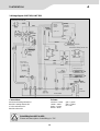
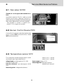
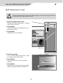
1
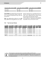
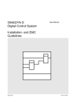
Service-Instruction
COOL
3110
ABSORPTION REFRIGERATOR + OVEN for RECREATION VEHICLES
RMT 7650
RMT 7850
RMT 7651
RMT 7851
RMT 7655
RMT 7855
Publications-Nr.:
599 5230-23 DE
© Dometic GmbH - 2005 - Subject to change without notice
T.B. MB 10/2005
English
Table of Contents
Page
1.0
Description of Model . . . . . . . . . . . . . . . . . . . . . . . . . . .
3
2.0
Operating . . . . . . . . . . . . . . . . . . . . . . . . . . . . . . . . . . . .
5
3.0
Components . . . . . . . . . . . . . . . . . . . . . . . . . . . . . . . . . .
6
4.0
Installation . . . . . . . . . . . . . . . . . . . . . . . . . . . . . . . . . . . 10
5.0
Optionen . . . . . . . . . . . . . . . . . . . . . . . . . . . . . . . . . . . . . 16
6.0
Service/Maintenance/Tables . . . . . . . . . . . . . . . . . . . . . . 18
7.0
Further Documentation . . . . . . . . . . . . . . . . . . . . . . . . . 22
The instruction on hand is completed and revised regularly.
2
Models
1
PIEZO RMT 7XX0 Series
MES RMT 7XX1 Series
AES RMT 7XX5 Series
RMT 7650
RMT 7651
RMT 7655
RMT 7850
RMT 7851
RMT 7855
Piezo-fridges are equipped with a manual energy
selector and a thermostatic regulation of the cooling compartment temperature during 230V and
gas operation.
ped with electronics for controlling the function
elements and status indication of the active operation source. Additionally AES-fridges provide
the possibility of manual energy selection.
At both ranges of models, the cooling compartment temperature is regulated thermostatically in
all operation sources (12 V-/230 V~/GAS)
MES- fridges (Manual Energy Selection) and AES
fridges (Automatic Energy Selection) are equip-
1.1 Technical Data
Model
Dimensions
H x W x D (mm)
depth incl. door
Gross
capacity
incl. freezer
Usable
Connection
capacity of
Mains / Battery
freezer comp
Consumption
electricity / gas
in 24hrs
Net
weight
Ignition
Piezo automat.
RMT 7650(L) 1515 x 525 x 596
150 lit.
26 lit.
190 W/170 W
ca. 3,2 KWh/380 g
59,0 kg
•
RMT 7850(L) 1515 x 525 x 651
175 lit.
31 lit.
190 W/170 W
ca. 3,2 KWh/380 g
60,7 kg
•
RMT 7651(L) 1515 x 525 x 596
150 lit.
26 lit.
190 W/170 W
ca. 3,2 KWh/380 g
59,0 kg
•
RMT 7851(L) 1515 x 525 x 651
175 lit.
31 lit.
190 W/170 W
ca. 3,2 KWh/380 g
60,7 kg
•
RMT 7655(L) 1515 x 525 x 596
150 lit.
26 lit.
190 W/170 W
ca. 3,2 KWh/380 g
59,0 kg
•
RMT 7855(L) 1515 x 525 x 651
175 lit.
31 lit.
190 W/170 W
ca. 3,2 KWh/380 g
60,7 kg
•
Oven only
28 lit.
CMBO
i
100 g/h (gas only)
•
This instruction contains descriptions essentially to MES and AES models .
A description of the function components (compact fitting, burner etc.) of the PIEZO
models can be found in the SERVICE HANDBOOK "Absorption-Refrigerators for
Recreational Vehicles".
3
1
Models
1.2 General Remarks
Main components accessible via ventilation
grille and control panel.
If no supply voltage is available the LED lights
"red" at AES appliances.
It does not light at MES appliances.
At AES models the selected energy is displayed by the corresponding LED (i.e. 230V)
and the "AUTO" LED simultaneously.
Fridge does not necessarily have to be deinstalled for service and alteration.
Gas supply point on back of fridge;
accessible via lower ventilation grille.
means : Improved Access for Maintenance !
Low voltage control at 230V~ operation
During the refuelling stop (switch over time to
gas mode 15 min.) the appliance is
in stand-by operation mode and only the
"AUTO" LED lights up (no supply of energy
meanwhile).
Switching to an other energy source at
200 V +/- 7V
No low voltage control at 12V -- operation
NOTE: The refuelling delay cannot be reseted
by switching off/on or manual choice of
energy.
Lighting with one light bulb 12V/2W ;
Do not use 8V- light bulbs!
Power supply for burner control device and
gas valve: 1,5 V controlled by the electronics /
power module.
Operation with 12V ; 230V is displayed "green"
with LED .
Switch over times / time delay at "AUTO"function at AES models :
Priority
1. 12 V- Solar
5s
12 V Solar
230 V~
5s
2. 230 V~
3. 12 V- D+
4. Liquid gas
20
s
20 s
0s
10
5s
5s
100 s
5s
5s
5s
12 V D+
Gas
15 min.
4
Operating
2
2.1 Controls
Manual energy selection / manual ignition (RMT 7650, RMT 7850)
G
D
E
A
B
A = switch on and energy selection (Refrigerator)
D = switch for frame heating
B = gas/electric thermostat AC/DC (Refrigerator)
E = operating display frame heating
C = manual ignition button “Piezo ignition/battery
igniter”
C
J
G = Galvanometer (Refrigerator)
(Refrigerator)
J = switch on / thermostat (Oven)
Manual energy selection / automatical ignition MES (RMT 7651, RMT 7851)
D
E
A
C
B
A = switch on and energy selection (Refrigerator)
D = switch for frame heating
B = gas/electric thermostat AC/DC (Refrigerator)
J
E = operating display frame heating
C = operating displays 3 LEDs (Refrigerator)
J = switch on / thermostat (Oven)
for max. 30 seconds. Operation via electrical energy is indicated with green, gas operation is indicated with yellow.
Button A is used for selection of the wanted energy source; Button B is used for setting the temperature. Using the gas modus, the ignition is carried
out fully automatically (ticking noise can be heard)
Automatical + manual energy selection / automatical ignition AES (RMT 7655, RMT 7855)
E
A
C
F
B
J
H
A = switch on and energy selection (Refrigerator)
B = gas/electric thermostat AC/DC (Refrigerator)
C = operating displays 4 LEDs (Refrigerator)
D = switch for frame heating
E = operating display frame heating
F = temperature setting display
H = dimmer for LED-displays
(only accessable when door opens)
J = switch on / thermostat (Oven)
5
3
Components / Refrigerator
3.1 Components (RMT 7650, RMT 7850 only)
The equipping of the RMT 7XX0 (piezo)-fridges
differs from the traditional piezo-fridges of the
RM7-series, due to the standard battery-igniter for
gas operation.
A = Energy selector switch (underneath cover)
B = Battery of the oven’s igniter
C = Compact fitting
D = Battery igniter for gasburner of the fridge
A
C
B
D
3.2 Electronics/Power module (RMT 7xx1, RMT 7xx5 only)
The space-saving electronics is mounted directly
behind the front fascia. The LED for status indication, energy selection switch and temperature regulation are integrated. In conformity with the models RMT 7xx1 and
RMT 7xx5 there are electronics for MES and AES.
The MES-electronics does not have contacts for
the D+ and solar signal. The AES-electronic is additionally equipped with the dimmer.
Typisch AES: 4 LED
Kennzeichnung mit Art.-Nr.
Codierte Kompaktstecker
3.3 Temperature-Sensor / NTC (nur RMT 7xx1, RMT
All operation modes (DC/AC/GAS) are controlled thermostatically.
The temperature sensor is fitted at the post
evaporator.
6
Components / Refrigerator
3
3.4 Wiring scheme (MES/AES)
D+
Solar
POWER MODULE
BURNER
CONTROL
DEVICE
12 V-
DC-heating element
230 V~
12 V-
AC-heating element
Temp. Sensor
Interior light 12 V/2 W
GAS VALVE
Ignition electrode
Ionisation electrode
3.5 Operating priniciple
Function electronics (Power module)
Burner Control Device P810
The electronics regulates the controlling of the
function elements according to the selected energy source, e.g. power supply of the Burner Control
Device. The AES-electronics additionally regulates the selection of the most convenient energy
source, according to the priority "230 V~/12 V/GAS", as well as the 230V~ under voltage control
(no under voltage control at 12V-Modus), as well
as the delay in switching to the gas mode during a
refuelling stop.
The Burner Control Device controls the ignition of
the flame during the gas modus and supervises
the ignition (security-ignition ca. 30sec.). Flame recognition and controlling is carried out via an ionization electrode in the burner chamber (flame
failure device). For security reasons, there is an
additional earth contact on the burner chassis,
which leads to the Burner Control Device The controlling of the gas valve GV100 is also carried out
via the Burner Control Device.
The function electronics also controls the temperature sensor and the lighting. The electronics is
protected against possible short circuit errors of
the Burner Control Device with a 500mA fuse.
Gasvalve GV100
The gas valve GV100 consists of two seriesconnected valves (increase of security). The valve
locks itself at a pressure of > 1 bar.
7
3
Components / Refrigerator
3.6 Gas operation components
At the backside of the fridge the gas (safety) valve
and the burner control device is assembled,
which are operated with approx. 1.5V, controlled
by the electronics.
1
1 Burner Control Device P810
(igniter, flame control, flame safety device)
2
2 Gasvalve GV100
(gas sefety device, includes 2 serial mounted
valves; automatically closed at a
pressure > 1bar)
3 Gas connection below
3
4 Ignition electrode
5 Ionisation electrode
1
4
6 Ground
(Connection to burner control device)
6
5
The ionization control is used for flame recognition
in the burner chamber. The burner chassis serves
as earth contact.
8
Components / Oven
3
3.7 Components
A
A
C
A
A
B
B
1
2
3 < 407 146 554
4 < 407 146 555
5 Gas burner 30 mbar < 407 146 564
Gas burner 50 mbar < 407 146 565
6 < 407 146 556
7 < 407 146 557
A
B
1
2/C
3
4
5
6
7
= Screws of the rearwall
= Gas connection
= temperature sensor
= Terminal 12 V DC
= Ignition device
9
= Ignition electrode
= Gas burner
= Thermo couple
= Gas thermostat
4
Installation
4.1 Electrical installation
Power line connection
It is advisable to run the incoming supply through
an 2 Amps on-board fuse or automatic
circuit breaker. The power cable must be laid in such
a way that it does not come in contact with hot
components of the cooling unit/burner or with
sharp edges.
The power must be supplied via a properly earthed socket outlet or hardwired connection.
Where a socket outlet is used for the mains
connection lead, the outlet must be freely accessible.
Battery connection
The 12V circuit must be protected with a 16A
(20A RM 76xx) fuse
The mains 12V connection cable is connected
(observing correct polarity) to a terminal strip. The
cabling must be by the shortest possible route to
the battery and alternator respectively. (Connection A, B)
Cross-sectional area
of cable
The heating element circuit A/B must be connected
to the vehicle battery by a suitable ignition operated relay in order that the 12V supply is only live
while the vehicle ignition is switched on.The
connection C/D (interior light, electronics ; cable
black / violet) must be permanently attached, and
must not be cut-out when the vehicle ignition key is
turned off.
Length of cable
6 mm2
10 mm2
<6m
>6m
Cross sect.-area of cable: recomm. min. 1,5 mm2
Connections:
A = Ground heating element DC
B = Plus heating element DC
C = Ground electronics
D = Plus electronics
RMT 76X1 L
RMT 78X1 L
C D
RMT 76X5 L
RMT 78X5 L
12 V DC
permanent supply
D+ = alternator signal
S+ = AES-input-control signal
(solar charge regulator
C
D
above
Connection of
12 V heating
element
B
below
A
For RMT 7xx5 L-models only!
Terminal block
The D+ control (Dynamo +) must be connected
to the respective vehicle terminal.
respective solar charging controllers are
available from a specialized dealer. The "Solar"
(S+) control connection must be connected to
the respective terminal of the solar charging
controller (AES output).
(D+ = alternator signal while motor is running).
Cable cross-sections
D+ connection:
There are no particularly high current flows via
the D+ and S+ connection; therefore no particularly large cross-section is required for these
connections (approx. 1mm²).
Solar control input (S+):
Connection only when using a solar system with
a solar charging controller with AES output. The
10
Installation
4
Terminal block MES RMT 7xx1 above
red:
+ cable 12 V heatingelement via ignition
operated relay and fuse 20A
white:
– cable 12 V heatingelement
violett:
+ cable 12 V permanent connection to
electronics
black:
– cable 12 V permanent connection to
electronics
D+ =
Input Dynamo+ from alternator
S+ =
Input control signal from solar charge
regulator
red
black
white
violet
Fig. 1
Terminal block AES RMT 7xx5 above
sw:
prepared D+ - cable
red:
+ cable 12 V heatingelement via ignition
operated relay and fuse 20A
white:
– cable 12 V heatingelement
violett:
+ cable 12 V permanent connection to
electronics
black:
sw
red
black
– cable 12 V permanent connection to
electronics
violet
white
Fig. 2
Terminal block RMT 7xx1, RMT 7xx5 below
At the models RM76xx additional terminals are
assembled on the lower backside, seperated into
connetions "Electronics / D+" and "Heating element".
Fig. 3
Please note:
12V DC" means 12V connection to heating element via ignition operated relay. Do not
compare with "D+"- input signal of the alternator! "D+" and "S+" are different connections ( Do not exchange each other) !
11
4
Installation
4.2 Wiring diagram
heating element DC
1. Wiring diagram RMT 7650, RMT 7850 / manual ignition
resistor (replaced by a bridge for 24V
power supply)
terminal block
heating element DC
switch frame
heating
lighting DC
Ground
Reed contacts (sensor switch)
thermo couple
Ground
mains
connection
Ground
battery igniter
heating element AC
Connections:
Colours:
A = Ground heating element DC
B = Plus heating element DC
C = Ground frame heating / Interior light
D = Plus Interior light
schwarz = black
violett = violet
braun = brown
weiss = white
12
grün = green
gelb = yellow
rot = red
Installation
4
2. Wiring diagram RMT 7651, RMT 7851
permanently connection DC
C
D
Burner
Control
Device
ionisation
electrode
ignition unit
ignition
plug
Ground
gas burner
terminal block heating element DC
Switch
Frame
Heating
B
Gas
Valve
A
Reed contacts
(sensor switching)
heating element DC
temp. sensor
lighting DC
heating element AC
mains
connection
Ground
Power Module
Connections:
Colours:
A = Ground heating element DC
B = Plus heating element DC
C = Ground electronics
D = Plus electronics
schwarz = black
violett = violet
braun = brown
weiss = white
Retrofitting from MES to AES :
Please note description of retrofitting ch. "5.0"
13
grün = green
gelb = yellow
rot = red
4
Installation
3. Wiring diagram RMT 7655, RMT 7855
permanently connection DC
C
Burner
Control
Device
D
ionisation
electrode
ignition
plug
ignition unit
Ground
gas burner
terminal block heating element DC
Switch
Frame
Heating
Gas
Valve
B
A
Reed contacts
(sensor switching)
temp. sensor
heating element DC
lighting DC
heating element AC
Ground
mains
connection
Power Module
Connections:
Colours:
A = Ground heating element DC
B = Plus heating element DC
C = Ground electronics
D = Plus electronics
schwarz = black
violett = violet
braun = brown
weiss = white
grün = green
gelb = yellow
rot = red
Exchange of previous AES II -models with new RM 76xxAES :
The heating element circuit must be connected to the vehicle battery by a suitable ignition operated relay in order that the 12V supply is only live while the vehicle ignition is
switched on. The connection C/D (interior light, electronics ; cable black / violet) must
be permanently attached.
14
Installation
4
4.3 Gas-Connection
The gas connection to the appliance is effected by means of a suitable coupling tube fitting L8, DIN
2353-ST, complying with EN 1949 (e. g. Ermeto).
!
DO NOT UNSCREW THE PRE-INSTALLED GAS CONNECTIONS ON THE VALVE
WHILE INSTALLING THE FRIDGE !
1 Gas valve GV100
2 Gas connection
1
2
SW 14
max.
15 Nm
SW 17
Observe torques in the case of exchange the
gas valve.
max.
20 Nm
Gas valve (refrigerator)
Main connection gas supply
Gas supply to the oven
15
5
Options
5.1 Upgrading MES – AES
can fast and easily be carried out by an authorised
service partner or a dealer.
Purchasing an appliance RMT 7xx1 for manual
operation, the customer has also the possibility to
upgrade the appliance to the RMT 7xx5 with automatic energy selection. The possibility of free manual energy selection remains.
An MES-fridge can be upgraded without taking
it out of the recess.
Changing the function electronics and setting in
an appropriate front fascia, as well as changing
the rating label (obtainable in a set) the upgrade
Note: RMT 7xx0 - models with piezo ignition cannot be upgraded.
A
B
D+-cable already NOT laid
on the vehicle!
Affix sticker "UPGRADE-KIT INSTALLED"
12V-operation (heating) possible while the
ignition operated relay is switched on.
Connect D+ -signal cable by means of a
quick clamping connector with cable "+12V
12V operation is "active" in ignition lock
position "1" (i.e. engine not running!)
DC HE"
Exchange of electronics/power module and
panel
D+-cable already ALREADY laid
on the vehicle!
Connect prepared D+ -wire (of the vehicle)
with “D+” - terminal
16
Options
5
12V operation is only "active" while engine is running (D+ signal from alternator).
Upgrade kit
The kit includes :
AES-Power-Module
Sitck-on lable
D+/S+-Upgrade-cable
Quick clamping connector
New panel
Alteration of RMT 7XX1 into model RMT 7XX5
D+/S+ upgrade cable
included in the supply
Pull off control knobs and put aside.
Loosen both screws and remove panel.
Loosen retaining screws of electronics housing
Pull out MES function electronics and pull off
connectors (these are coded).
1
Situation A : D+ signal cable installed in vehicle.
6
A
Connect black strand of "D+/S+" cable to terminal
"D+" and connect vehicle's "D+" signal cable.
12V operation is only "active" while engine is
running (D+ signal from alternator).
Mount electronics module and secure.
Fit NEW panel and mount control
knobs.
17
Attach sticker "AES Upgrade-Kit installed" next to data plate.
6
Service/Maintenance/Tables
6.1 Gas valve GV100
Situation B : no D+ signal cable installed in vehicle
Insert black strand of "D+/S+" cable up to the
stopper into the quick clamping connector together with the red cable A (+ terminal heating element, terminal 6) and press connector together.
ground
Pin 2
Pin 1
12V operation is "active" in ignition lock
position "1" (i.e. engine not running!)
6.2 Burner Control Device P810
Connect D+/S+ upgrade cable (black/white) with
plug-in contact X106 on the electronics. Install
AES function electronics.
6.3 Temperature sensor NTC
This component includes two gas valves in serial
mounting (as part of gas safety device).
valve 1 : pin 1 - ground
valve 2 : pin 2 - ground
Power supply : approx. 1.5 V
voltage supply : per valve approx. 0,7V - 0,9V
(switched on gas mode)
Measuring points: flat plug connector
between pin 2 and pin 3
inductive resistance : per valve approx. 48-50
Ohm
Measuring points: voltage and resistance
18
Service/Maintenance/Tables
6
6.4 Electronics / Power module
NTC - Table of resistance
Temperature in °C
0
5
10
15
20
resitance in kOhm
27,70
22,29
18,07
14,74
12,11
6.5 12 V DC/Current draw
MES RMT 7XX1
AES RMT 7XX5
AC mode
Gas mode
Auto
AC mode
Auto
Gas mode
ca. 50 – 60 mA
ca. 60 – 70 mA
•
•
ca. 60 – 80 mA*
ca. 70 – 90 mA*
ca. 70 – 90 mA*
ca. 90 – 100 mA*
*depends on temperature setting (switched on LEDs) and dimmed LEDs
19
6
Service/Maintenance/Tables
6.6 Malfunction of the fridge
Failure
25
Possible cause
Fuse 500 mA: Protection of burner control device
10,00
Measuring point:
electronics / power module
loosen contacts X108
cable white / brown
In case of a defective fuse, exchange the complete power module
In case of a defective sensor, the fridge is in operation steadily (recognisable : temperature drops,
cooling compartment rather cold)
20
Service/Maintenance/Tables
6
6.7 Removal of oven
!
Before removing the oven, make sure, that the fridge is electrically voltage free and that
the stop valve of the gas supply is closed!
Electrical operation (MES + AES)
Buzzing noise when switching on = "blinking
relay" on the electronics
Gas operation
Yellow LED flashes immediately when changing into gas modus
12 V DC connection
Gas operation
Deflagration when first ignition
Gas connection
RMT 7X50
RMT 7X51
RMT 7X55
Electrical operation
12 V- connection faulty on the vehicle, voltage colapses under elctrical load
Gas operation
Burner Control Device or power module
defective
Fixing screws
Gas operation
Ignition plug too close to the burner housing,
Adjust according to Bulletin 599 5202-38
21
7
Further Documentation
7.1 Service Bulletin
1. Dismantle the fascia (grid) above the fridge, installed by the OEM. The chimney is accessible.
2. Release the chimney tube and push it up.
3. Disconnect the 12V- and the gas connection.
The connections are on the backside of the
oven. When the fridge is built in correctly, the
connections are accessible after taking out the
upper vent grill.
4. Take off all turning knobs cautiously. Loosen
two screws (see picture) and take off the front
fascia
Pls note:
The flame indicator is tightened to the front fascia of piezo-fridges RMT 7xx0
After having loosened the screws, put down
the fascia cautiously.
5. In order to be able to take out the oven more
easily, demount the function electronics if you
have a MES or AES fridge
Loosen the screws of the fixing of the oven.
Then pull out the oven.
Pls note: Putting down the fridge, make sure
the fittings will no be damaged.
RM 6XX0, RM6XX1, RM 7XX0
Zu hoher Prüfdruck
Publication-Nr.: 599 5178-77 de/
Service 2003.07.31 BO/KV
Umbau der Türverriegelung
Publication-Nr.: 599 5182-05 de/
Service 2003.10.01 BO/KV
Flamme hält nicht
Publication-Nr.: 599 5183-07 de/
Service 2003.10.16 BO/KV
Service-Kit Gasanschlussrohr
Publication-Nr.: 599 5190-29 de/
Service 2004.01.21 BO/KV
Leak test valve GV100
Publication-Nr.: 599 5194-66 en/
Service 2004.02.26 BO/KV
Ignition problems RM 7XX1 and RM 7XX5
Put down the oven sideways.
22
Publication-Nr.: 599 5202-38 en/
Service 2004.06.08 BO/KV
Notes
23
Dometic GmbH
Technisches Büro Service Dokumentation
In der Steinwiese 16
D-57074 Siegen
Tel.: +49 (0) 271 / 692-0
Fax.: +49 (0) 271 / 692-322
www.dometic.de/caravan
www.dometic.com