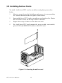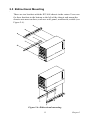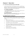
1
IPC-644
Micro-Box 4-slot Industrial
Chassis
User Manual
Copyright Notice
Advantech Co., Ltd copyrights this documentation and the software
included with this product in December, 2005. All rights are reserved.
Advantech Co., Ltd. reserves the right to make improvements in the products described in this manual at any time without notice.
No part of this manual may be reproduced, copied, translated or transmitted in any form or by any means without the prior written permission of
Advantech Co., Ltd. Information provided in this manual is intended to
be accurate and reliable. However, Advantech Co., Ltd. assumes no
responsibility for its use, or for any infringements of the rights of third
parties which may result from its use.
Acknowledgements
Intel®, Pentium® III, and Celeron® are trademarks of Intel Corporation.
IPC-644, PCA-6104P4-0B1, and PCA-6104-0C1 are trademarks of
Advantech Co., Ltd.
All other product names or trademarks are the properties of their respective owners.
On-line Technical Support
For technical support and service, please visit our support website at:
http://www.advantech.com/support
Part No. 2002064411
December, 2005
IPC-644 User Manual
ii
3rd Edition
A Message to the Customer
Advantech customer services
Each and every Advantech product is built to the most exacting specifications to ensure reliable performance in the harsh and demanding conditions typical of industrial environments. Whether your new Advantech
equipment is destined for the laboratory or the factory floor, you can be
assured that your product will provide the reliability and ease of operation
for which the name Advantech has come to be known. Your satisfaction
is our primary concern. Here is a guide to Advantech's customer services.
To ensure you get the full benefit of our services, please follow the
instructions below carefully.
Technical support
We want you to get the maximum performance from your products. So if
you run into technical difficulties, we are here to help. For the most frequently asked questions, you can easily find answers in your product documentation. These answers are normally a lot more detailed than the ones
we can give over the phone.
So please consult this manual first. If you still cannot find the answer,
gather all the information or questions that apply to your problem, and
with the product close at hand, call your dealer. Our dealers are well
trained and ready to give you the support you need to get the most from
your Advantech products. In fact, most problems reported are minor and
can be easily solved over the phone.
In addition, free technical support is available from Advantech engineers
every business day. We are always ready to give advice on application
requirements or specific information on the installation and operation of
any of our products.
iii
Product warranty
Advantech warrants to you, the original purchaser, that each of its products will be free from defects in materials and workmanship for two years
from the date of purchase.
This warranty does not apply to any products which have been repaired or
altered by persons other than repair personnel authorized by Advantech,
or which have been subject to misuse, abuse, accident or improper installation. Advantech assumes no liability under the terms of this warranty as
a consequence of such events.
If an Advantech product is defective, it will be repaired or replaced at no
charge during the warranty period. For out-of-warranty repairs, you will
be billed according to the cost of replacement materials, service time and
freight. Please consult your dealer for more details.
If you think you have a defective product, follow these steps:
1.
Collect all the information about the problem encountered. (For
example, type of PC, CPU speed, Advantech products used, other
hardware and software used, etc.) Note anything abnormal and list
any on-screen messages you get when the problem occurs.
2.
Call your dealer and describe the problem. Please have your manual, product, and any helpful information readily available.
3.
If your product is diagnosed as defective, obtain an RMA (return
material authorization) number from your dealer. This allows us to
process your return more quickly.
4.
Carefully pack the defective product, a fully completed Repair and
Replacement Order Card and a photocopy proof of purchase date
(such as your sales receipt) in a shippable container. A product
returned without proof of the purchase date is not eligible for warranty service.
5.
Write the RMA number visibly on the outside of the package and
ship it prepaid to your dealer.
IPC-644 User Manual
iv
Initial Inspection
Before you begin installing your motherboard, please make sure that the
following materials have been shipped:
• IPC-644 Chassis
• User Manual
• Warranty Card
• Accessory box with a package of screws (for fastening the passive
backplane and disk drives), a spare filter, an EMI shield, and a 4-pin
power wire.
If any of these items are missing or damaged, contact your distributor or
sales representative immediately. We have carefully inspected the IPC644 mechanically and electrically before shipment. It should be free of
marks and scratches and in perfect working order upon receipt. As you
unpack the IPC-644, check it for signs of shipping damage. (For example,
damaged box, scratches, dents, etc.) If it is damaged or it fails to meet the
specifications, notify our service department or your local sales representative immediately. Also notify the carrier. Retain the shipping carton and
packing material for inspection by the carrier. After inspection, we will
make arrangements to repair or replace the unit.
v
IPC-644 User Manual
vi
Contents
Chapter
1 General Information ....................................... 2
1.1
1.2
1.3
1.4
1.5
Introduction ............................................................. 2
Specifications .......................................................... 2
Power Supply Specifications................................... 3
Table 1.1: Power Supply ................................................. 3
Environment Specifications .................................... 3
Table 1.2: Environment Specifications ........................... 3
Dimensions.............................................................. 4
Figure 1.1: Dimensions of IPC-644 ................................. 4
1.6
Chapter
Safety Precautions................................................... 5
2 System Setup.................................................... 8
2.1
Removing the Chassis Cover .................................. 8
Figure 2.1: Removing the chassis cover ........................... 8
2.2
Installing a Backplane ............................................. 9
Figure 2.2: Installing a backplane .................................... 9
2.3
Installing Add-on Cards ........................................ 10
Figure 2.3: Inserting the add-on card ............................. 10
2.4
Installing Disk Drives ........................................... 11
2.4.1 Removing the Upper Cage from the Chassis ...... 11
Figure 2.4: Removing the upper cage ............................. 11
2.4.2 Installing a HDD or FDD .................................... 12
Figure 2.5: Installing disk drives into the housing ......... 12
2.5
Bidirectional Mounting ......................................... 13
Figure 2.6: Bidirectional mounting ................................ 13
Chapter
3 Operation ....................................................... 16
3.1
The Front and Rear Panel of IPC-644................... 16
3.1.1 Switch and Button ............................................... 16
3.1.2 LED Indicators .................................................... 16
3.2
Replacing the Cooling Fan.................................... 16
Figure 3.1: Replacing the fan ......................................... 17
3.3
Replacing the Filter ............................................... 18
Figure 3.2: Replacing the filter ....................................... 18
3.4
Replacing the power supply .................................. 19
Figure 3.3: Replacing the power supply ......................... 19
iii
Table of Contents
Appendix A Exploded Diagram ........................................ 22
Figure A.1: Exploded diagram ........................................ 22
Appendix B Backplane Options ........................................ 24
Appendix C Safety Instructions ........................................ 26
C.1 English................................................................... 26
C.2 German - Wichtige Sicherheishinweise ................ 27
IPC-644 User Manual
iv
1
CHAPTER
2
General Information
Chapter 1 General Information
1.1 Introduction
The micro-box industrial chassis IPC-644 is an ultra-compact 4-slot mininode chassis that is ideal for embedded applications. It's even compact
enough to fit in some mobile systems such as cars, boats, or other vehicles. It's specifically designed for half-size card applications and supports
up to four PCI or four ISA cards.
IPC-644 can be placed on the desk or mounted bidirectionally with the
supplied brackets. It can be easily bottom- or left-mounted onto most surfaces, such as walls or workbenches. The shockproof drive bay design
protects the system against harsh industrial environments or unexpected
shock. All these outstanding features make IPC-644 the best solution for
space, price, performance and total cost of ownership.
1.2 Specifications
• Construction: Heavy-duty steel
• Disk drive capacity: One 3.5" external and one 3.5" internal drive bay
• I/O interfaces on rear panel: Three reserved openings: one for the 25pin parallel port, two for the 9-pin COM port
• LED Indicators on Front Panel: LEDs for Power (green) and HDD
activity (green)
• Switches and Buttons: Power switch on rear panel and System Reset
button on front panel
• Cooling fan: One 53 CFM (9 x 9 cm) cooling fan behind the front
panel
• Air Filter: One filter behind the front cover
• Gross Weight: 4.5 kg (10 lb)
• Dimensions (W x H x D): 135 x 209 x 305 mm (5.3" x 8.2" x 12")
• Chassis Color: Beige (Pantone 414U)
IPC-644 User Manual
2
1.3 Power Supply Specifications
Table 1.1: Power Supply
Model Name
1757000170
Power rating
150 W max. (ATX, PFC)
Input voltage
100 ~ 240 Vac (Full range)
Output voltage
+5 V @ 15 A, +3.3 V @ 17 A, +12 V @ 8 A, -12 V @ 0.8 A,
+5 Vsb @ 2 A
Minimum load
+5 V @ 1 A, +3.3 V @ 0.5 A, +12 V @ 2 A, +5 Vsb @ 0.1 A
MTBF
100,000 hours @ 25° C
Safety
CE/UL/TUV/CB
1.4 Environment Specifications
Table 1.2: Environment Specifications
Environment
Temperature
Humidity
Vibration
Safety
Operating
Non-operating
0 to 40°C (32 to 104°F)
-20 to 60°C (-4 to 140°F)
10 to 85% @ 40°C, non10 to 95% @ 40°C,
condensing
non-condensing
1 G rms
2G
CE compliant, UL/cUL approved
3
Chapter 1
1.5 Dimensions
Figure 1.1: Dimensions of IPC-644
IPC-644 User Manual
4
1.6 Safety Precautions
Warning!
Always completely disconnect the power cord from
your chassis whenever you work with the hardware.
Do not make connections while the power is on. Sensitive electronic components can be damaged by
sudden power surges. Only experienced electronics
personnel should open the PC chassis.
Caution!
Always ground yourself to remove any static charge
before touching the motherboard, backplane, or addon cards. Modern electronic devices are very sensitive to static electric charges. As a safety precaution,
use a grounding wrist strap at all times. Place all
electronic components on a static-dissipative surface
or in a static-shielded bag when they are not in the
chassis.
FCC
This device complies with the requirements in part 15 of the FCC rules.
Operation is subject to the following conditions:
1.
This device may not cause harmful interference
2.
This device must accept any interference received, including interference that may cause undesired operation
This equipment has been tested and found to comply with the limits for a
Class A digital device, pursuant to Part 15 of the FCC Rules. These limits
are designed to provide reasonable protection against harmful interference when the equipment is operated in a commercial environment. This
equipment generates, uses, and can radiate radio frequency energy and, if
not installed and used in accordance with the instruction manual, may
cause harmful interference to radio communications. Operation of this
device in a residential area is likely to cause harmful interference in
which case the user will be required to correct the interference at his/her
own expense. The user is advised that any equipment changes or modifications not expressly approved by the party responsible for compliance
would void the compliance to FCC regulations and therefore, the user's
authority to operate the equipment.
5
Chapter 1
IPC-644 User Manual
6
CHAPTER
2
2
System Setup
Chapter 2 System Setup
The following procedures are provided to assist you in installing a passive backplane, add-on cards, and disk drives into the IPC-644. Please
refer to Appendix A, Exploded Diagram, for details of all the parts of the
IPC-644.
Note
Use caution when installing or operating the components with the chassis open. Be sure to turn off the
power, unplug the power cord and ground yourself by
touching the metal chassis before you handle any
components inside the machine.
2.1 Removing the Chassis Cover
To remove the cover of IPC-644, please refer to Figure 2.1 and proceed as
follows.
1.
Loosen the seven screws on the top and the right of the chassis.
2.
Remove the chassis cover gently.
Figure 2.1: Removing the chassis cover
IPC-644 User Manual
8
2.2 Installing a Backplane
The IPC-644 supports a 4-slot PCI or 4-slot ISA backplane. Please refer
to Figure 2.2 to install a backplane.
1.
Remove chassis cover.
2.
Get the EMI spring plate from the accessory box. Attach it to the
backplane.
3.
Align the backplane to the screw holes in the chassis and then fasten it with the four screws supplied.
4.
Connect the 20-pin ATX power connector from the power supply to
the backplane.
EMI spring plate
Backplane
Figure 2.2: Installing a backplane
9
Chapter 2
2.3 Installing Add-on Cards
To install a half-sized CPU card or an add-on card, please proceed as
below.
1.
Select a vacant slot on the backplane and remove its corresponding
I/O bracket attached to the rear plate of the chassis.
2.
Insert a half-sized CPU card or an add-on card into the slot. Fasten
the card with a screw on the top of the I/O bracket.
3.
Repeat these steps if there is more than one card.
4.
For a half-sized CPU card, connect the power switch, reset switch,
power LED, and HDD LED cables to the CPU card.
Figure 2.3: Inserting the add-on card
IPC-644 User Manual
10
2.4 Installing Disk Drives
The disk drive bay is located on the lower deck of the chassis. Users need
to detach the upper cage first before they install an HDD or FDD. Please
refer to the following procedure.
2.4.1 Removing the Upper Cage from the Chassis
1.
Unplug the 20-pin ATX power connector on the backplane.
2.
Detach the four screws located on the front and rear of the upper
cage chassis (refer to Figure 2.4).
3.
Take the upper cage out of the chassis.
Figure 2.4: Removing the upper cage
11
Chapter 2
2.4.2 Installing a HDD or FDD
1.
Loosen the five screws (one screw is for grounding) on the disk
drive mounting bracket and then lift it out.
2.
Insert the disk drive into its proper location in the disk drive mounting bracket, and then fix it in place with the supplied screws (see
Figure 2.5).
3.
Connect a 34-pin flat cable from the CPU card to an FDD, or a 40pin flat cable from the CPU card to an IDE HDD. Plug in the power
connector into each disk drive.
4.
Return the disk drive mounting bracket back to its original location
and fasten it with the five screws.
5.
Return the upper cage and secure it with the four screws.
6.
Plug the 20-pin ATX power supply connector into the backplane.
Disk drive mounting bracket
Floppy disk drive
Hard disk drive
Figure 2.5: Installing disk drives into the housing
IPC-644 User Manual
12
2.5 Bidirectional Mounting
There are two brackets with the IPC-644 chassis in the carton. Users can
fix these brackets to the bottom or the left of the chassis and mount the
chassis onto most surfaces, such as a wall, panel, workbench, or table (see
Figure 2.6).
Figure 2.6: Bidirectional mounting
13
Chapter 2
IPC-644 User Manual
14
CHAPTER
3
2
Operation
Chapter 3 Operation
3.1 The Front and Rear Panel of IPC-644
On the front panel, there are LED indicators for power and HDD status,
and there is a small reset button which allows users to reboot the system.
The power switch is on the rear panel to reduce the chance of an accidental shutdown. The panel buttons are described below.
3.1.1 Switch and Button
• Power On/Off switch: Press this switch to turn the system on or off.
• Reset button: Press this button to reboot the system.
3.1.2 LED Indicators
When the system power is on, the PWR LED is always green. When the
HDD is being accessed, the HDD LED flashes green.
3.2 Replacing the Cooling Fan
There is an easy to maintain cooling fan which is near the front of the
chassis. To replace the cooling fan, please refer to Figure 3.1 and proceed
as follows.
1.
Remove the chassis cover.
2.
Disconnect the cooling fan power connector from the backplane.
3.
Loosen the two screws on the top of the fan bracket and pull it out.
4.
Loosen the four screws on the fan module.
5.
Fix the new cooling fan on the bracket by re-attaching the four
screws and then sliding the fan module into the chassis.
6.
Fasten the two screws on the top of the fan module so that it can be
fixed to the chassis.
7.
Reconnect the fan power connector.
8.
Return the chassis cover and fasten it.
IPC-644 User Manual
16
Figure 3.1: Replacing the fan
17
Chapter 3
3.3 Replacing the Filter
The filter is to protect the chassis from dust and other particles from the
work environment, and to extend the system longevity. It's better to
replace the filter periodically. There is one easy to maintain filter on the
front of the cooling fan in the IPC-644. To replace the filter, please refer
to Figure 3.2 and proceed as follows.
1.
Remove the two screws on the filter cover and pull it downwards.
2.
Replace the filter with a new one.
3.
Return the filter cover and fix the filter cover with the two screws.
Figure 3.2: Replacing the filter
IPC-644 User Manual
18
3.4 Replacing the power supply
To replace the power supply, refer to Figure 3.3 and proceed as follows.
1.
Unplug the AC power cord from the power supply.
2.
Remove the chassis cover.
3.
Unplug the 20-pin ATX power connector from the backplane.
4.
Remove the upper cage (refer to section 2.4.1).
5.
Unplug the power connectors from all disk drives.
6.
Remove the three screws on the chassis rear plate and the nut,
which fixes the power supply in the chassis, then take out the
power supply.
7.
Place a new power supply into the chassis and fasten it with the
screws and the nut.
8.
Return the upper cage and fasten it.
9.
Plug the 20-pin ATX power connector into the backplane and plug
other power connectors into the disk drives and peripherals.
10.
Return the chassis top cover and plug in the power cord.
Nut
Power supply
Figure 3.3: Replacing the power supply
19
Chapter 3
IPC-644 User Manual
20
A
APPENDIX
2
Exploded Diagram
Appendix A Exploded Diagram
Figure A.1: Exploded diagram
IPC-644 User Manual
22
B
APPENDIX
2
Backplane Options
Appendix B Backplane Options
IPC-644 supports 4-slot PCI or 4-slot ISA backplanes as below. Contact a
local sales representative for detailed information.
Model Name
Bus
PCI
PCI/ISA
ISA
AGP
SATA
PCA
-6104P4-0B1
4 (32-bit) --
--
--
--
PCA
-6104-0C1
--
4
--
--
IPC-644 User Manual
--
24
C
APPENDIX
2
Safety Instructions
Appendix C Safety Instructions
C.1 English
1.
Read these safety instructions carefully.
2.
Keep this installation reference guide for later reference.
3.
Disconnect this equipment from any AC outlet before cleaning. Do
not use liquid or spray detergents for cleaning. Use a damp cloth.
4.
For pluggable equipment, the power outlet must be installed near
the equipment and must be easily accessible.
5.
Keep this equipment away from humidity.
6.
Put this equipment on a reliable surface during installation. Dropping it or letting it fall could cause damage.
7.
The openings on the enclosure are for air convection. Protect the
equipment from overheating. DO NOT COVER THE OPENINGS.
8.
Make sure the voltage of the power source is correct before connecting the equipment to the power outlet.
9.
Position the power cord so that people cannot step on it. Do not
place anything over the power cord.
10.
All cautions and warnings on the equipment should be noted.
11.
If the equipment is not used for a long time, disconnect it from the
power source to avoid damage by transient over-voltage.
12.
Never pour any liquid into an opening. This could cause fire or
electrical shock.
13.
Never open the equipment. For safety reasons, the equipment
should be opened only by qualified service personnel.
14.
If any of the following situations arises, get the equipment checked
by service personnel:
a The power cord or plug is damaged.
b Liquid has penetrated into the equipment.
c The equipment has been exposed to moisture.
d The equipment does not work well, or you cannot get it to work
according to the installation reference guide.
e The equipment has been dropped and damaged.
f
The equipment has obvious signs of breakage.
IPC-644 User Manual
26
15.
DO NOT LEAVE THIS EQUIPMENT IN AN UNCONTROLLED
ENVIRONMENT WHERE THE STORAGE TEMPERATURE IS
BELOW -20° C (-4° F) OR ABOVE 60° C (140° F). THIS MAY
DAMAGE THE EQUIPMENT.
The sound pressure level at the operator's position according to IEC 7041:1982 is equal to or less than 70 dB (A).
DISCLAIMER: This set of instructions is given according to IEC 704-1.
Advantech disclaims all responsibility for the accuracy of any statements
contained herein.
C.2 German - Wichtige Sicherheishinweise
1.
Bitte lesen sie Sich diese Hinweise sorgfältig durch.
2.
Heben Sie diese Anleitung für den späteren Gebrauch auf.
3.
Vor jedem Reinigen ist das Gerät vom Stromnetz zu trennen. Verwenden Sie Keine Flüssig-oder Aerosolreiniger. Am besten dient
ein angefeuchtetes Tuch zur Reinigung.
4.
Die Netzanschlußsteckdose soll nahe dem Gerät angebracht und
leicht zugänglich sein.
5.
Das Gerät ist vor Feuchtigkeit zu schützen.
6.
Bei der Aufstellung des Gerätes ist auf sicheren Stand zu achten.
Ein Kippen oder Fallen könnte Verletzungen hervorrufen.
7.
Die Belüftungsöffnungen dienen zur Luftzirkulation die das Gerät
vor überhitzung schützt. Sorgen Sie dafür, daß diese Öffnungen
nicht abgedeckt werden.
8.
Beachten Sie beim Anschluß an das Stromnetz die Anschlußwerte.
9.
Verlegen Sie die Netzanschlußleitung so, daß niemand darüber
fallen kann. Es sollte auch nichts auf der Leitung abgestellt werden.
10.
Alle Hinweise und Warnungen die sich am Geräten befinden sind
zu beachten.
11.
Wird das Gerät über einen längeren Zeitraum nicht benutzt, sollten
Sie es vom Stromnetz trennen. Somit wird im Falle einer Überspannung eine Beschädigung vermieden.
12.
Durch die Lüftungsöffnungen dürfen niemals Gegenstände oder
Flüssigkeiten in das Gerät gelangen. Dies könnte einen Brand bzw
elektrischen Schlag auslösen.
27
Appendix C
13.
Öffnen Sie niemals das Gerät. Das Gerät darf aus Gründen der elektrischen Sicherheit nur von authorisiertem Servicepersonal geöffnet werden.
14.
Wenn folgende Situationen auftreten ist das Gerät vom Stromnetz
zu trennen und von einer qualifizierten Servicestelle zu überprüfen:
a Netzkabel oder Netzstecker sind beschädigt.
b Flüssigkeit ist in das Gerät eingedrungen.
c Das Gerät war Feuchtigkeit ausgesetzt.
d Wenn das Gerät nicht der Bedienungsanleitung entsprechend
funktioniert oder Sie mit Hilfe dieser Anleitung keine Verbesserung erzielen.
e Das Gerät ist gefallen und/oder das Gehäuse ist beschädigt.
f
Wenn das Gerät deutliche Anzeichen eines Defektes aufweist.
15.
Bitte lassen Sie das Gerät nicht unbehehrt hinten unter -20° C (-4°
F) oder oben 60° C (140° F), weil diesen Temperaturen das Gerät
zerstören könten.
Der arbeitsplatzbezogene Schalldruckpegel nach DIN 45 635 Teil 1000
beträgt 70dB(A) oder weiger.
DISCLAIMER: This set of instructions is provided according to IEC7041. Advantech disclaims all responsibility for the accuracy of any statements contained herein.
IPC-644 User Manual
28