1
TEC Thermal Printer
B-480 SERIES
Maintenance Manual
Document No. EO18-33004
Original Jun., 1999
(Revised
)
PRINTED IN JAPAN
WARNING!
Follow all manual instructions. Failure to do so could create safety hazards such as fire or
electrocution.
NOTES: 1. Manual instructions must be followed when installing option kits or adding cables
to avoid system failures and to insure proper performance and operation.
2. Failure to follow manual instructions or any unauthorized modification,
substitution or change to this product will void the limited product warranty.
EO18-33004
(Revision Date: Dec. 14, 2001)
TABLE OF CONTENTS
Page
1. UNPACKING ...........................................................................................1- 1
1.1 Procedures ......................................................................................1- 1
1.2 Checks .............................................................................................1- 1
2. MAJOR UNIT REPLACEMENT ..............................................................2- 1
2.1 Replacing the PS Unit .....................................................................2- 2
2.2 Replacing the CPU PC Board ......................................................... 2- 3
2.3 Replacing the Centronics I/F PC Board ...........................................2- 4
2.4 Replacing the I/O PC Board ............................................................2- 5
2.5 Replacing the Stepping Motor ......................................................... 2- 6
2.6 Replacing the Ribbon Motors ..........................................................2- 7
2.7 Replacing the Solenoid (QP Model only) ......................................... 2- 8
2.8 Replacing the Print Head ................................................................2- 10
2.9 Replacing the Platen and Feed Roller ............................................2- 11
2.10 Replacing the Paper Sensor ...........................................................2- 13
2.11 Replacing the Ribbon Back Tension Block ..................................... 2- 14
2.12 Replacing the Pinch Roller Shaft Ass'y ..........................................2- 15
2.13 Correcting Skew Printing ................................................................2- 17
3. INSTALLATION PROCEDURE FOR THE OPTIONAL EQUIPMENT .... 3- 1
3.1 PCMCIA PC Board (B-8700-PC-QM) .............................................. 3- 1
3.2 EXP I/O PC Board (B-8700-IO-QM) ................................................ 3- 4
3.3 Cutter Module (B-4205-QM) ............................................................3- 6
3.4 Ribbon Saving Module (B-4905-R-QM) ...........................................3- 8
3.5 Strip Module (B-4905-H-QM) ..........................................................3- 10
3.6 Fanfold Paper Guide Module (B-4905-FF-QM) ..............................3- 13
3.7 Cutter Module (B-8204-QM) ...........................................................3- 14
4. TROUBLESHOOTING .............................................................................4- 1
5. DIAG. TEST OPERATION .......................................................................5- 1
5.1 Outline of the Diag. Test Operation .................................................5- 1
5.2 Self Test Mode ................................................................................5- 3
5.3 Parameter Setting Mode .................................................................5- 14
5.4 Test Print Mode ..............................................................................5- 53
5.5 Sensor Setting Mode ......................................................................5- 60
5.6 RAM Clear Mode ............................................................................5- 65
5.7 IP Address Setting Mode ................................................................5- 70
5.8 BASIC Setting Mode .......................................................................5- 72
EO18-33004
Page
6. ON LINE OPERATION ............................................................................ 66.1 Reset Operation ..............................................................................66.2 Dump Mode .....................................................................................67. PROGRAM DOWNLOAD ........................................................................ 77.1 Outline of Features ..........................................................................77.2 Software Installation ....................................................................... 77.2.1 System Requirements ........................................................ 77.2.2 Setup ..................................................................................77.3 Install Program for B-482 .................................................................7-
1
1
2
1
1
1
1
2
4
CAUTION:
1. This manual may not be copied in whole or in part without prior written permission of TOSHIBA
TEC.
2. The contents of this manual may be changed without notification.
3. Please refer to your local Authorized Service representative with regard to any queries you may
have in this manual.
Copyright © 1999
by TOSHIBA TEC CORPORATION
All Rights Reserved
570 Ohito, Ohito-cho, Tagata-gun, Shizuoka-ken, JAPAN
EO18-33004
1. UNPACKING
1.1 Procedure
1. UNPACKING
1.1 Procedure
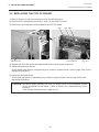
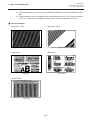
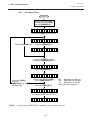
1) Open the carton.
2) Unpack the accessories from the carton.
3) Unpack the side pad (L)/(R) and the printer from the carton.
4) Place the printer on the level surface.
Owner's Manual
Unpacking Procedure
Side Pad (L)
Thermal Printer
Rear Pad
Power Cord
Side Pad (R)
Fan Filter
(QP model only)
Carton
Fig. 1-1
1.2 Checks
1) Check for damages or scratches on the machine.
2) Confirm that none of the accessories are missing.
NOTE:
Keep the carton and side pads for later transport.
1-1
EO18-33004
2. MAJOR UNIT REPLACEMENT
2. MAJOR UNIT REPLACEMENT
2. MAJOR UNIT REPLACEMENT
WARNING!
Disconnect the power cord before replacing the main parts.
CAUTION:
1. NEVER separate the ribbon motors from the attaching plate, (bracket) because doing so will
change their adjustment. (See Fig. 2-11)
2. NEVER remove the two screws painted red on the side of the print block. (See Fig. 2-15)
3. NEVER remove the four screws on the side of the print block. (See Fig. 2-15)
4. NEVER remove unmentioned screws because doing so will change their adjustment.
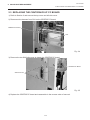
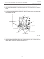
1) Turn the power off.
2) Open the top cover to remove the four FL-3x5 screws. Slide the top cover to the left to release the
damper and remove the top cover.
3) Remove the seven screws (FL-4x5 and B-4x5) to remove the left side cover.
4) Disconnect the FAN motor connector from the PS unit.
Top Cover
Left Side Cover
Screw (FL-3x5)
FAN Motor
Damper
Screw (B-4x5)
Screw (FL-4x5)
Fig. 2-1
NOTE: Instructions to remove the top cover and left side cover are omitted from each removal/
installation procedure provided below.
■ Lubrication
CAUTION: 1. Lubrication:
2. Kinds of oil:
During parts replacement
FLOIL G-488: 1kg kan (Part No. 19454906001)
Any machine is generally in its best condition when delivered; therefore, it is necessary to try to keep
this condition. Unexpected failure occurs due to lack of oil, debris or dust. To keep its best condition,
periodically clean the machine and apply proper kinds of oil to each part in which lubrication is needed.
Although the frequency of lubrication varies according to how much the machine is used, at least it is
necessary to lubricate before the machine becomes dry. It is also necessary to wipe off excessive oil
as it collects dirt.
CAUTION: Do not spray the inside of the printer with lubricants unsuitable oil can damage the
mechanism.
2-1
EO18-33004
2. MAJOR UNIT REPLACEMENT
2.1 Replacing the PS Unit, I/F PC Board and CPU PC Board
2.1 Replacing the PS Unit
CAUTION: Replace only with same type and ratings of fuse for continued protection against
risk of fire.
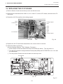
1) Remove the I/O PC board. (Refer to Section 2.4).
2) Remove the three FL-4x6 screws and disconnect the two connectors to detach the PS unit.
Screw (FL-4x6)
Connector
PS Unit
Screw (FL-4x6)
Fig. 2-2
2-2
EO18-33004
2. MAJOR UNIT REPLACEMENT
2.2 REPLACING THE CPU PC BOARD
2.2 REPLACING THE CPU PC BOARD
1) Refer to Section 2 and remove the top cover and left side cover.
2) Disconnect the harnesses from CN2, 5, and 7 on the CPU PC board.
3) Remove the four SM-3x6 screws to detach the CPU PC board.
CN2
SM-3x6 screw
CN5 CN7
CPU PC Board
Fig. 2-3
4) Replace the CPU PC board and reassemble in the reverse order of removal.
5) Adjust the black mark sensor.
As the black mark sensor is adjusted by key entries in system mode, refer to page 5-44 for the
adjustment procedure.
6) Adjust the feed gap sensor.
As the feed gap sensor is adjusted by key entries in system mode, refer to page 5-45 for the
adjustment procedure.
CAUTION: Be careful when replacing the CPU PC board, since a non-resettable counter
(IC15) is installed on this board. (Refer to Section 5.2.1 Maintenance Counter
Printing.)
If this counter should be reset, replace IC15.
2-3
EO18-33004
2. MAJOR UNIT REPLACEMENT
2.3 REPLACING THE CENTRONICS I/F PC BOARD
2.3 REPLACING THE CENTRONICS I/F PC BOARD
1) Refer to Section 2 and remove the top cover and left side cover.
2) Disconnect the harness from CN1 on the CENTRO PC board.
CENTRO PC Board
CN1
Fig. 2-4
3) Remove the two SM-3x8 screws to detach the CENTRO PC board.
CENTRO PC Board
SM-3x8 Screw
Fig. 2-5
4) Replace the CENTRO PC board and reassemble in the reverse order of removal.
2-4
EO18-33004
2. MAJOR UNIT REPLACEMENT
2.4 REPLACING THE I/O PC BOARD
2.4 REPLACING THE I/O PC BOARD
1) Refer to Section 2 and remove the top cover and left side cover.
2) Disconnect the harnesses from CN2 to 4, 8 to 14 and 17 on the I/O PC board, and remove the FL4x6 screw.
3) Detach the I/O PC board from the locking support.
CN14
I/O PC Board
Locking Support
CN17
CN8
CN13
CN12
CN11
CN10
FL-4x6 Screw
CN9
Locking Support
CN2 CN3
CN4
Fig. 2-6
4) Replace the I/O PC board and reassemble in the reverse order of removal.
5) Adjust the ribbon end sensor.
Use the following Ribbons; TTM-78 (Maker: Fujicopian)
1 Set the ribbon so that the ribbon end sensor can detect the ribbon. Turn the power on.
2 Turn the VR1 so that the voltage between Frame plate (GND) and Pin TPRETR is 3.0 ± 0.2 V with
an oscilloscope.
3 Turn the power off and mount the left side cover and top cover.
Pin TPRETR
VR1
Fig. 2-7
2-5
EO18-33004
2. MAJOR UNIT REPLACEMENT
2.5 Replacing the Stepping Motor
Range: 1V/0.2 m sec.
Voltage
3.0 – 0.2 V
VR1
GND
Fig. 2-8
2.5 Replacing the Stepping Motor
1) Remove the two black screws to detach the front plate, remove the two FL-4x6 screw and FL-4x8
screw to detach the belt cover.
Front Plate
Belt Cover
Black Screw
FL-4x8 Screw
FL-4x6 Screw
2) Unclamp and disconnect the connector from CN17 on the I/O PC board.
2-6
Fig. 2-9
EO18-33004
2. MAJOR UNIT REPLACEMENT
2.6 Replacing the Ribbon Motors
3) Remove the two SM-4x8 screws, loosen the two belts from the pinion gear, and remove the stepping
motor.
Partition
Platen Belt
I/O PC Board
CN7
Clamp
Screw (SM-4x8)
CN13
Pinion Gear
Feed Roller Belt
PS Unit
Stepping Motor
Fig. 2-10
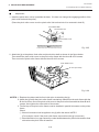
4) When replacing the stepping motor, place the platen belt first then the feed roller belt around the pinion
gear so that the partition is positioned between two belts. Hold down the stepping motor at 3.5 kg ±
300 g force and secure it so that the belts have no slack or disengagement.
5) Reassemble in the reverse order of removal.
2.6 Replacing the Ribbon Motors
CAUTION: NEVER separate the ribbon motors from the attaching plate because doing so will
change their adjustment.
1) Disconnect the two connectors and remove the two SM-3x5B screws to detach the ribbon motors.
FLOIL G-488
Attaching Plate
Ribbon Motor
Screw (SM-3x5B)
FLOIL G-488
Dowels
Connector (Red)
Attaching Plate
Connector (Black)
Screw (SM-3x5B)
Ribbon Motor
Fig. 2-11
2) Replace the ribbon motors, then align the dowels to attach the ribbon motors. Reassemble in the
reverse order of removal.
2-7
EO18-33004
2. MAJOR UNIT REPLACEMENT
2.7 Replacing the Solenoid
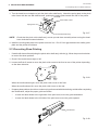
2.7 Replacing the Solenoid (QP Model only)
NOTE: The following procedure can be employed without removing the top cover and left side cover.
1) Before removing the ribbon stopper, check its attaching direction for later installation. Remove the
ribbon stopper from the ribbon shaft on which the ribbon is wound.
2) Remove the two SM-4x8B screws, disconnect the connector CN1 on the RSV PC board to detach the
solenoid unit.
Connector CN1 (3 pin)
Solenoid Attaching Plate
Screw (SM-4x8B)
Ribbon Shaft
CN2 (2 pin)
Ribbon Stopper
RSV PC Board
Print Block
Fig. 2-12
3) Remove the two SM-3x5B screws and disconnect the connector CN2 on the RSV PC board to detach
the solenoid.
Solenoid
Connector CN2 (2 pin)
Solenoid Attaching Plate
RSV PC Board
Screw (SM-3x5B)
Fig. 2-13
2-8
EO18-33004
2. MAJOR UNIT REPLACEMENT
2.7 Replacing the Solenoid
NOTE: Make sure to remove any dust that appears during removal or installation because it may affect
the print quality.
4) Replace the solenoid and attach it to the solenoid attaching plate.
5) Assemble the solenoid unit so that the head up link engages the spring pin.
Solenoid
Spring Pin
Head Up Link
Fig. 2-14
CAUTION: Take care to orient the screw so that they are vertically aligned with the solenoid
attaching plate.
6) Reasemble in the reverse order of removal.
2-9
EO18-33004
2. MAJOR UNIT REPLACEMENT
2.8 Replacing the Print Head
2.8 Replacing the Print Head
CAUTION:
1. NEVER touch the element when handling the print head.
2. NEVER touch the connector pins to avoid a breakdown of the print head by static electricity.
3. NEVER remove the two screws painted red on the side of the print block.
4. NEVER remove the four screws on the side of the printer block.
5. NEVER remove the print block, otherwise it requires the adjustment of the position when
reassembling.
NOTE: The following procedure can be employed without removing the top cover and the left side
cover.
NOTE: Never loosen screws other than two SM-4x8B.
1) Turn the head lever clockwise to lower the print head. Remove the two SM-4x8B screws.
2) Turn the head lever counterclockwise and disconnect the two connectors to detach the print
head from the print block.
Screw (SM-4x8B)
Screws
(NEVER remove these screws.)
Print Block
Connector
B
A
A
B
Head Lever
Print Head
Screws painted red
(NEVER remove these screws.)
Connector
Fig. 2-15
3) Replace the print head and connect the connectors.
4) Turn the head lever clockwise and secure the print head with screws in the holes B .
NOTE: Use caution to prevent damage to the element during print head adjustment.
2-10
EO18-33004
2. MAJOR UNIT REPLACEMENT
2.9 Replacing the Platen and Feed Roller
■
Adjusting the print head position
1. Fit the jig in the platen and strip shaft.
2. Press the jig at an angle of 45 until it is sung against the print head. Then secure the print head.
Platen
Print Head
Jig
Strip Shaft
Jig
Ceramic
Strip Shaft
Fig. 2-16
Platen
3. Remove the jig.
4. Refer to page 5-68 and clear the maintenance counter.
5. Refer to page 5-53 and perform test print.
NOTES: 1. Use caution to prevent damage to the element during adjustment of the print head.
2. The jig used for the B-472/572 printer is also used.
2.9 Replacing the Platen and Feed Roller
CAUTION:
The pinch roller belt assembled inside the printer does not need to be replaced because it
receives less load.
1) Remove the front plate and belt cover. (Refer to Section 2-5.)
2) Turn the head lever counterclockwise, then remove the E-ring (E-3) and Hold Shaft and release the
ribbon shaft holder plate.
E-ring (M3)
Head Lever
Hold Shaft
Ribbon Shaft Holder Plate
2-11
Fig. 2-17
EO18-33004
2. MAJOR UNIT REPLACEMENT
2.9 Replacing the Platen and Feed Roller
3) Remove the six screws (FL-4x6, B-4x12 and P-3x12) to detach the right plate Ass’y.
Right Plate
Screw (B-4x12)
Screw (FL-4x6)
Screw (B-4x12)
Screw (P-3x12)
Fig. 2-18
4) Loosen the two screws (SM-4x8B) fixing the stepping motor to loosen the platen belt and feed roller
belt.
5) Remove the platen belt to detach the platen. Remove the feed roller belt to detach the feed roller.
6) Remove both bearings from the platen or feed roller.
Feed Roller Belt
Holder
Feed Roller (Gray)
Platen Belt
Holder
Holder
Platen (Black)
Fig. 2-19
7) Replace the platen and feed roller, put on the belt and assemble it with the printer. The longer belt
is the platen belt.
8) Attach the right plate.
9) Hold down the stepping motor and secure it so that the belts have no slack or disengagement.
(Refer to Section 2-5.)
10) Reassemble in the reverse order of removal.
2-12
EO18-33004
2. MAJOR UNIT REPLACEMENT
2.10 Replacing the Paper Sensor
2.10Replacing the Paper Sensor
NOTE: Turn the knob until the paper sensor reaches full forward.
1) Refer to Section 2.9 and detach the right plate.
2) Remove the FL-4x6 screw to detach the media guide plate.
Media Sensor
1.5 ~ 2.5 mm
Printer Block Base
Media Guide Plate
FL-4x6 Screw
Fig. 2-20
3) Disconnect the connectors for the paper sensor.
4) Remove M1.5 E-ring, M3 washer and paper sensor unit.
5) Remove M1.5 E-ring, turn the knob counter clockwise, then remove the paper sensor.
Connector (2 pin)
Paper Sensor
Connector (4 pin)
Washer (M3)
Sensor Shaft
E-ring (M1.5)
Knob
E-ring (M1.5)
Fig. 2-21
6) Replace the paper sensor and reassemble in the reverse order of removal.
7) After replacing the paper sensor, refer to page 5-44/5-45 and adjust the voltage.
2-13
EO18-33004
2. MAJOR UNIT REPLACEMENT
2.11 Replacing the Ribbon Back Tension Block
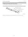
2.11 Replacing the Ribbon Back Tension Block
1) Turn the head lever counterclockwise, then release the ribbon shaft holder plate.
2) Remove the M3 E-ring and the two M3 washers to remove the ribbon back tension block. At this time,
remove the back tension stopper and ribbon back tension washer from the ribbon back tension block.
Ribbon Back Tension Washer
Back Tension Stopper
Ribbon Back Tension Block
Washer (M3)
E-ring (M3)
Fig. 2-22
3) Replace the ribbon back tension block and reassemble in the reverse order of removal.
2-14
EO18-33004
2. MAJOR UNIT REPLACEMENT
2.12 Replacing the Pinch Roller Shaft Ass'y
2.12Replacing the Pinch Roller Shaft Ass’y
1) Turn the head lever to position 3, and release the ribbon shaft holder plate.
2) Remove the black screw to detach the media guide plate.
Media Sensor
1.5 ~ 2.5 mm
Printer Block Base
Media Guide Plate
FL-4x6 Screw
Fig. 2-23
3) Remove the SM-4x8B screw to detach the spring plate.
4) Remove the six B-4x12 screws to detach the pinch roller cover.
5) Remove the E-5 E-ring to loosen the pinch roller belt, and remove the pinch roller shaft ass’y.
SM-4x8B
E-5
Spring Plate
Pinch Roller Belt
Pinch Roller Cover
W-8
B-4x12
Pinch Roller Shaft Ass'y
Pinch Roller Cover
Fig. 2-24
6) After replacing the pinch roller shaft ass’y, make the following adjustment while you reassemble the
pinch roller shaft ass’y in the reverse order of removal.
2-15
EO18-33004
2. MAJOR UNIT REPLACEMENT
2.12 Replacing the Pinch Roller Shaft Ass'y
■
Adjustment
1. Install the pinch roller unit so it parallels the base. If it does not, change the engaging position of the
pinch roller belt and the pulley.
(Place the pinch roller cover over the pinch roller Unit so that hole A is centered in hole B.)
Pinch Roller Belt
B
Pinch Roller Unit
Pinch Roller Cover
Pully
A
Fig. 2-25
2. Attach the jig to the platen, feed roller and pinch roller shaft as shown in the figure below.
Then attach the pinch roller cover to the pinch roller frame with the three B-4x12 screws.
Then secure the pinch roller frame with the three B-4x12 screws.
Pinch Roller Cover
B-4x12 (6 screws)
Jig
Fig. 2-26
NOTES: 1. Replace the platen and the feed roller prior to attaching the jig.
2. Attach the jig while the pinch roller frame is tentatively attached to the main frame with the
B-4x12 screws. Secure the pinch roller cover to the pinch roller frame with the three B-4x12
screws, then tighten the other side of the screws.
3. The flat top of the pinch roller frame must be installed in parallel to bosses on the printer
frame.
Check
1 Check if excessive load is applied to the jig after the above NOTE 2.
(For example, check if the pinch roller frame moves when the jig is removed.)
2 Check that there is no gap caused by a slant shaft between the pinch roller and the feed
roller when the pinch roller is lowered.
2-16
EO18-33004
2. MAJOR UNIT REPLACEMENT
2.13 Replacing the Pinch Roller Shaft Ass'y
3. Turn the head lever clockwise to lock the pinch roller shaft ass’y. Attach the spring plate to the pinch
roller frame with the two SM-4x8B screws, pushing the spring plate toward the rear of the printer.
SM-4x8B
Pinch Roller Frame
Spring Plate
Pinch Roller Shaft Ass'y
Fig. 2-27
NOTE: Check that the pinch roller shaft ass’y moves up and down smoothly when turning the head
lever clockwise/counterclockwise.
4. Install the media guide plate to the printer so there is a 1.5 to 2.5 mm gap between the media guide
plate and the printer block base.
2.13Correcting Skew Printing
• If media still skews after adjusting the pinch roller shaft ass’y with the jig, follow the procedure below
to correct the skew problem.
1. Check if the media skews right or left.
2. Loosen the B-4x12 screw to move the pinch roller cover to the front or rear of the printer depending
on the skew direction.
Fig. 2-28
When the media skews right, move the pinch roller cover to the front.
When the media skews left, move the pinch roller cover to the rear.
• If a paper skew problem should occur when using rolls wound with labels facing outside after completing
the modification, adjust the paper guide as follows.
*
In case the label skews to the right side of the print head, move the guide downward.
*
In case the label skews to the left side of the print head, move the guide upward.
Guide Plate
Fig. 2-29
2-17
3. INSTALLATION PROCEDURE FOR THE OPTIONAL EQUIPMENT
EO18-33004
(Revision Date: Jan. 28, 2000)
3.1 PCMCIA PC BOARD (B-8700-PC-QM)
3. INSTALLATION PROCEDURE FOR THE OPTIONAL
EQUIPMENT
WARNING!
Make sure to unplug the power cord before installing the optional equipment.
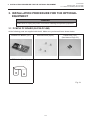
3.1 PCMCIA PC BOARD (B-8700-PC-QM)
All the following parts are supplied with the kit. Make sure you have all items shown below.
PCMCIA PC Board (1 pc.)
SM-3x8 Screw (4 pcs.)
Ferrite Core (1 pc.)
(See Note on Page 3-3)
PCB Holder Plate (1 pc.)
Fig. 3-1
3-1
3. INSTALLATION PROCEDURE FOR THE OPTIONAL EQUIPMENT
EO18-33004
(Revision Date: Jan. 28, 2000)
3.1 PCMCIA PC BOARD (B-8700-PC-QM)
1. Refer to Section 2 and remove the top cover and left side cover.
2. Remove the two FL-3x4 screws to detach the blind plate.
Blind Plate
FL-3X4 Screw
Fig. 3-2
NOTE: Keep the FL-3x4 screws and blind plate safe.
3. Disconnect the harness from CN2 on the CPU PC board.
Fix the PCB holder plate to the CPU PC board with the SM-3x8 screw so that the PCB holder plate
aligns with the PCB support plate.
PCB Holder Plate PCB Support Plate
CN2
Harness
CN9
SM-3x8 Screw
CPU PC Board
Fig. 3-3
3-2
3. INSTALLATION PROCEDURE FOR THE OPTIONAL EQUIPMENT
EO18-33004
(Revision Date: Jan. 28, 2000)
3.1 PCMCIA PC BOARD (B-8700-PC-QM)
4. Connect the CN51 on the PCMCIA PC board to the CN9 on the CPU PC board. (Refer to Fig. 3-2)
5. Fix the PCMCIA PC board with the three SM-3x8 screws onto the CPU PC board and the PCB holder
plate.
CPU PC Board
PCB Holder Plate
SM-3x8 Screw
SM-3x8 Screw
PCMCIA PC Board
Fig. 3-4
6. Return the harness to the CN2 on the CPU PC board.
Harness
PCMCIA PC Board
Fig. 3-5
7. Reassemble the left side cover and top cover in the reverse order of removal.
NOTE: Attach the ferrite core to any cable attached to a PCMCIA card (Example LAN card) that
may be inserted into the card slot. Place the ferrite core as close to the PCMCIA card as
possible.
3-3
3. INSTALLATION PROCEDURE FOR THE OPTIONAL EQUIPMENT
EO18-33004
(Revision Date: Jan. 28, 2000)
3.2 EXP I/O PC Board (B-8700-IO-QM)
3.2 EXP I/O PC Board (B-8700-IO-QM)
All the following parts are supplied with the kit. Make sure you have all items shown below.
EXP I/O PC Board (1 pc.)
Harness (1 pc.)
Fig. 3-6
1. Refer to Section 2 and remove the top cover and left side cover.
2. Remove the two FL-3x4 screws to detach the blind plate.
Blind Plate
FL-3X4 Screw
Fig. 3-7
NOTE: Keep the FL-3x4 screws and blind plate safe.
3. Remove the two SM-3x6 screws from the EXP I/O PC board.
EXP I/O PC Board
SM-3x6 Screw
Fig. 3-8
3-4
3. INSTALLATION PROCEDURE FOR THE OPTIONAL EQUIPMENT
EO18-33004
(Revision Date: Jan. 28, 2000)
3.2 EXP I/O PC Board (B-8700-IO-QM)
4. Fix the EXP I/O PC board on the rear cover with the two SM-3x6 screws removed in Step 3.
Rear Cover
SM-3x6 Screw
EXP I/O PC Board
Rear Cover
EXP I/O PC Board
Fig. 3-9
5. Connect the attached harness to CN1 on the EXP I/O PC board and CN6 on the I/O PC board.
I/O PC Board
EXP I/O PC Board
CN6
CN1
Harness
Fig. 3-10
6. Reassemble the left side cover and top cover in the reverse order of removal.
3-5
EO18-33004
3. INSTALLATION PROCEDURE FOR THE OPTIONAL EQUIPMENT
3.3 Cutter Module (B-4205-QM)
3.3 Cutter Module (B-4205-QM)
Description
Q'ty/Unit
Description
Q'ty/Unit
Cutter Unit
1
Cutter Attaching Screw
2
Cutter Cover
1
Screw (FL-4x6)
1
Take-up/Cutter Harness
1
Cleaner
1
1. Remove the top cover and left side cover. (See Fig. 2-1.)
2. Remove the front plate. (See Fig. 2-9.)
3. Remove the screw (SM-4 x 8B) and two connectors to detach the operation panel.
Screw (SM-4x8B)
Connector
Operation Panel
Fig. 3-11
4. Install the cutter unit with the attached screws (cutter attaching screw, FL-4 x 6).When installing the
cutter, make sure that the guide is not in contact with the platen. If it is, print failure or noise may be
caused.
Cutter Unit
Platen
Cutter Attaching Screw
Screw (FL-4x6)
Cutter Guide
Fig. 3-12
3-6
EO18-33004
3. INSTALLATION PROCEDURE FOR THE OPTIONAL EQUIPMENT
3.3 Cutter Module (B-4205-QM)
5. Connect the take-up/cutter harness to CN1 on the Cutter I/F PC board and CN5 on the I/O PC Board,
then fix it with the clamp.
Clamp
Connected to CN5 on
the I/O PC board
Cutter Unit
Cut I/F PC Board
Connector (CN1)
Take-up/Cutter Harness
Fig. 3-13
6. Mount the cutter cover with the two white screws.
Screw
Cutter Attaching Screw
Cutter Cover
Fig. 3-14
7. Reassemble the left side cover and the top cover in the reverse order of removal.
8. After reassembly is complete, perform a test print to confirm that the cutter works properly.
After printing a print sample at a speed of 6"/sec., feed the media about 33 mm and check that the
swing cutter works without error. After cutting the media, feed the media about 33 mm in the reverse
direction and check that it correctly stops at the print start position.
NOTE: Retain the parts that are removed during installation of the cutter unit. They will be required
when the printer is modified to a standard type.
Removed Parts
Front plate
Q'ty/Unit
1
Removed Parts
Black screws
3-7
Q'ty/Unit
2
EO18-33004
3. INSTALLATION PROCEDURE FOR THE OPTIONAL EQUIPMENT
3.4 Ribbon Saving Module (B-4905-R-QM)
■ Adjusting the Cutter Guide Plates
After replacing the cutter unit the following adjusting procedure should be employed to prevent
paper jams.
1. Attach the cutter guide plate A with two SM-4 x 6C screws so that the fixed cutter is positioned
0.1 mm to 0.4 mm above the bottom of the cutter guide plate A.
2. Attach the cutter guide plate B with two FL-4 x 8 screws so that there is a clearance of 0.5 mm between
the cutter guide plate A and cutter guide plate B using a clearance gauge.
Cutter Guide Plate A
Fixed Cutter
0.5 mm
0.1-0.4 mm
Screw (SM-4x6C)
Cutter Guide Plate B
Screw (FL-4x8)
Fig. 3-15
3.4 Ribbon Saving Module (B-4905-R-QM)
Description
Q'ty/Unit
Ribbon Saving Module
1
1. Turn the head lever counterclockwise to release the ribbon shaft holder plate.
2. Remove the ribbon stopper from the ribbon shaft on which the ribbon is wound. Before removing the
ribbon stopper, check its attaching direction for later installation. Remove the ribbon stopper from the
ribbon shaft on which the ribbon is wound.
3. Remove the two SM-4 x 8 screws to detach the solenoid attaching plate.
Screw (SM-4x8B)
Solenoid Attaching Plate
Ribbon Shaft
Ribbon Stopper
Print Block
Fig. 3-16
3-8
EO18-33004
3. INSTALLATION PROCEDURE FOR THE OPTIONAL EQUIPMENT
3.4 Ribbon Saving Module (B-4905-R-QM)
4. Pass the solenoid harness of the ribbon saving module through the opening from the print block side
and connect to CN15 on the I/O PC board. Fix the harness with the clamp.
5. Install the ribbon saving module on the print block.
6. Assemble the solenoid unit so that the head up link engages the spring pin.
7. Secure the ribbon saving module with the SM-4x8B screws removed in Step 3.
Ribbon Saving Module
Screw (SM-4x8B)
Opening
Clamp
Solenoid Harness
(Connected to CN5
on the I/O PC board)
Print Block
Solenoid
Ribbon Shaft
Spring Pin
Head Up Link
Fig. 3-17
8. Set the Ribbon Saving Module is ON. (Refer to Section 5.3.16)
NOTE: Make sure to remove any dust that appears during removal or installation because it may affect
the print quality.
CAUTION: Take care to orient the screws so that they are vertically aligned with the ribbon
saving module.
3-9
EO18-33004
3. INSTALLATION PROCEDURE FOR THE OPTIONAL EQUIPMENT
3.5 Strip Module (B-4905-H-QM)
3.5
Strip Module (B-4905-H-QM)
Description
Q'ty/Unit
Description
Q'ty/Unit
Rewinder Ass'y
1
Rewinder Guide Plate
1
Rewind Full Sensor (LED)
1
Screw (FL-4x6)
4
Strip Sensor (Tr)
1
Screw (SM-3x6B)
1
Strip Sensor (LED)
1
Screw (SM-4x6B)
2
Rewind Paper Guide
1
1. Remove the top cover and left side cover (See section 2-1.)
2. Remove the operation panel. (See section 3-3.)
3. Fasten the rewind paper guide to the base with the two SM-4 x 6B screws.
SM-4x6B
Rewind Paper Guide
Base
Fig. 3-18
3-10
EO18-33004
3. INSTALLATION PROCEDURE FOR THE OPTIONAL EQUIPMENT
3.5 Strip Module (B-4905-H-QM)
4. Pass the take-up harness of the rewinder ass’y and the longer harness of the rewind full sensor
through the hole of the main frame. Connect the take-up harness and rewind full sensor harness
to CN16 and CN5 on the I/O PC board respectively. Fix the harness at two points with the clamps.
5. Connect the connector of the rewind full sensor (LED) with the other harness of the rewind ass’y.
6. Align the notch of the take-up holder with the screw hole of the rewinder ass’y and attach it to the
printer with four FL-4 x 6 screws.
7. Attach the rewind full sensor (LED) to the base with SM-3 x 6B screw.
Rewind Full Sensor (LED)
Opening
Screw (SM-3x6B)
Clamp
Connected to CN5 and
CN18 on the I/O PC board
FL-4x6
Notch
Selection switch
Rewinder Ass'y
FL-4x6
Take-up Holder
Fig. 3-19
NOTE: You should change the selection switch position depending on the usage of the take-up holder.
Improper setting can affect the print quality.
STANDARD/PEEL OFF (STRIP):
Batch and strip types
REWINDER:
Built-in rewinder type
For the cutter type, the selection switch can be set to either position.
3-11
EO18-33004
3. INSTALLATION PROCEDURE FOR THE OPTIONAL EQUIPMENT
3.5 Strip Module (B-4905-H-QM)
8. Connect the shorter harness of the strip sensor (Tr) with the strip sensor harness (LED).
9. Pass the other the strip sensor (Tr) harness through the clamp and connect to CN16 on the I/O PC
Board.
10. Secure the strip sensors (Tr) and (LED) with SM-4 x 6B screw.
11. Fix the harness mentioned in Step 7 with the clamp. Be sure to wire the harness along with the main
frame, base and right plate.
Main Frame
Connected to CN16 on
the I/O PC board
Base
Right Plate
Strip Sensor (Tr)
Strip Sensor (LED)
Harness
Screw (SM-4x6B)
Fig. 3-20
12. Reassemble the operation panel, top cover and left side cover in the reverse order of removal.
13. When using the built-in rewinder in Batch mode, fit the rewinder guide plate to the strip shaft, then
attach it with the black screws which were removed in step 4.
3-12
EO18-33004
3. INSTALLATION PROCEDURE FOR THE OPTIONAL EQUIPMENT
3.6 Fanfold Paper Guide Module (B-4905-FF-QM)
3.6
Fanfold Paper Guide Module (B-4905-FF-QM)
Description
Q'ty/Unit
Fanfold Paper Guide (rear)
1
Fanfold Paper Guide (front)
1
1. Open the top cover.
2. Remove the T-4 x 8 screws to detach the paper guide ass'y at the center of the printer and attach the
fanfold paper guide (front) with these same screws.
Fanfold Paper Guide (front)
Screw (T-4x8)
Fig. 3-21
3. Remove the FL-4 x 5 screws to detach the blind plate on the back of the printer and attach the fanfold
paper guide (rear) with the same screws.
Screw (FL-4x5)
Fanfold Paper Guide (rear)
Screw (FL-4x5)
Fig. 3-22
3-13
EO18-33004
3. INSTALLATION PROCEDURE FOR THE OPTIONAL EQUIPMENT
3.7 Cutter Module (B-8204-QM)
3.7 Cutter Module (B-8204-QM)
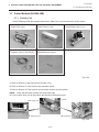
3.7.1 Packing List
All the following parts are supplied with the kit. Make sure you have all items shown below.
Cutter Unit (1 pc.)
Cutter Cover (1 pc.)
Harness (2 pcs.) (2 pin/9 pin)
SM-4x8 Screw (6 pcs.)
Cutter Driver Unit (1 pc.)
Fig. 3-23
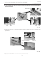
1) Refer to Section 2 and remove the left side cover.
2) Refer to Section 3.3 and remove the operation panel.
3) Refer to Section 2.5 and remove the two black screws and front plate.
NOTE: Keep the two black screws and front plate safe.
4) Fix the cutter drive unit to the printer with the three SM-4x8 screws.
Printer
Cutter Drive Unit
SM-4x8 Screw
SM-4x8 Screw
Fig. 3-24
3-14
EO18-33004
3. INSTALLATION PROCEDURE FOR THE OPTIONAL EQUIPMENT
3.7 Cutter Module (B-8204-QM)
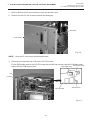
5) Connect the attached harness (9 pins) to CN7 on the cutter drive unit and CN5 on the I/O PC board,
and the attached harness (2 pins) to CN9 on the cutter drive unit and CN7 on the I/O PC board,
respectively.
I/O PC Board CN5 (9 pin) CN7 (2 pin)
Cutter Drive Unit CN9 (2 pin) CN7 (9 pin)
Fig. 3-25
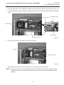
6) Reassemble the operation panel removed in Step 2. At this time, pass the harness through the
clearance not to be clamped by the operation panel.
Operation Panel
Clearance
Harneses
Fig. 3-26
7) Connect the four harnesses to CN8, 10 to 12 on the cutter drive unit.
CN8 CN12
CN10
CN11
Cutter Unit
Connectted to CN10
Connectted to CN8
Cutter Drive Unit
Connectted to CN12
Connectted to CN11
Fig. 3-27
3-15
EO18-33004
3. INSTALLATION PROCEDURE FOR THE OPTIONAL EQUIPMENT
3.7 Cutter Module (B-8204-QM)
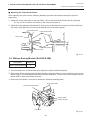
8) Fit the two hooks of the cutter drive unit into the notches, and then fix the cutter unit with the attached
three SM-4x8 screws.
SM-4x8 Screw
SM-4x8 Screw
Cutter Unit
Hook
Notch
Notch
Hook
Fig. 3-28
9) Attach the cutter cover on the cutter unit with two screws so that the hook turns on the cutter cover
open switch.
Cutter Unit
Cutter Cover Open Switch
Cutter Unit
Cutter
Cover
Screw
Hook
Fig. 3-29
10) Reassemble the left side cover in the reverse order of removal.
3-16
EO18-33004
3. INSTALLATION PROCEDURE FOR THE OPTIONAL EQUIPMENT
3.7 Cutter Module (B-8204-QM)
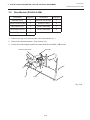
■ Adjust Cut Angle
When the cutter cuts media obliquely, follow the procedure below to adjust the cut angle.
1. Loosen the two SM-4x8B screws.
2. Move the guide plate back or forth so that the cutter is perpendicular to the media. Tighten the same
SM-4x8B screws.
SM-4x8B Screw
SM-4x8B Screw
Guide Plate
Fig. 3-30
3. Perform a test cut to check for a proper cut. Repeat the procedure, if necessary.
3-17
EO18-33004
4. TROUBLESHOOTING
4. TROUBLESHOOTING
4. TROUBLESHOOTING
Problems
Solution
Cause
Power is not turned 1. Input voltage to the printer is not within
ON.
the rated voltage.
(Check by CN1 on the PS unit.)
2. Output voltage from the printer is not
within the rated voltage.
(Check that the voltage between Pin 4
and Pin 6 (GND) of CN3 on the PS unit
is 27 V.
And check the voltage between Pin 1
and Pin 3 (GND) is 5 V.)
3. I/O PC board is not applied with
voltage.
(Check the voltage between Pin 4 and
Pin 6 (GND) of the CN12 on the I/O
PC board is 27 V.)
4. Failure of CPU PC board.
• Replace the power cable or power
inlet.
LED or LCD does not 1. Failure of the LED board/LCD
light.
2. Failure of the LCD/LED harness
3. Failure of the CPU PC board
• Replace the LED board/LCD.
• Replace the LCD/LED harness.
• Replace the CPU PC board.
Poor printing.
• Replace the PS unit.
• Replace the power harness.
• Replace the CPU PC board.
• Use the media approved by
TOSHIBA TEC.
• Clean the print head.
2. Dirty print head
3. The head lever fastens the print head • Fasten the head lever completely.
incompletely.
4. Alignment adjustment of the print head • Re-adjust the head.
is improper.
1. The print paper is of poor quality.
• Replace the print head.
Printer does not print. 1. Print head failure
2. Connection of the print head connector • Connect the harness completely,
or replace the harness.
is incomplete, a bad contact, or broken
wires.
3. Failure in the rewinding/feeding of the • Replace the ribbon rewind motor,
ribbon feed motor or I/O PC board.
ribbon.
• Replace the CPU PC board.
• Check the program.
4. Failure of the CPU PC board
• Replace the printer cable.
5. Failure of the software
6. Failure of the printer cable
4-1
EO18-33004
4. TROUBLESHOOTING
4. TROUBLESHOOTING
Problems
Solution
Cause
Dot missing
1. Broken element of print head
2. Broken wires of print head cable
3. Failure of the CPU PC board
4. Failure of the I/O PC board
•
•
•
•
Blurred print
1. Poor quality of media.
• Use only TOSHIBA TEC specified
media.
• Clean the print head and remove
the dust from the media.
2. Dust is attached to the media.
Ribbon wrinkle
1. Poor quality of the ribbon
Ribbon end error
1. Poor quality of the ribbon
Label feed failure
1. Paper is not set properly.
2. Paper of poor quality
Communication error
1. Failure of the communication cable
2. Failure of the RS-232C connector
3. Failure of the communication
connector
4. Failure of the PC or application
software
5. Failure of the CPU PC board
Replace the print head.
Replace the print head harness.
Replace the CPU PC board.
Replace the I/O PC board.
• Use only TOSHIBA TEC specified
ribbon.
2. Ribbon is not rewound or fed smoothly. • Replace the ribbon rewind motor
or ribbon feed motor.
• Use only TOSHIBA TEC specified
ribbon.
2. Improper voltage applied to the ribbon • Refer to page 2-4 to adjust the
end sensor
ribbon end sensor.
3. Failure of the ribbon end sensor
• Replace the ribbon end sensor.
4. Failure of the circuit which controls • Replace the I/O PC board.
the ribbon end sensor.
• Set the paper properly.
• Use the paper approved by
TOSHIBA TEC.
3. Improper adjustment of the feed gap • Re-adjust the sensor.
sensor or black mark sensor.
4. Failure of the feed gap sensor or black • Replace the feed gap sensor or
mark sensor
black mark sensor.
5. Labels cannot be stripped off the • Replace the take-up motor or I/O
backing paper or the backing paper
PC board.
with labels cannot be wound properly.
6. The cutter mechanism is not installed • Install the cutter mechanism
properly.
properly.
7. Failure of the stepping motor
• Replace the stepping motor or
I/O PC board.
4-2
• Replace the cable.
• Replace the connector.
• Replace the connector.
• Modify the program.
• Replace IC2 (MC145407).
If the trouble is not solved, replace
the CPU PC board.
EO18-33004
(Revision Date: Jan. 12, 2001)
TABLE OF CONTENTS
Page
5. DIAG. TEST OPERATION ........................................................................5- 1
5.1 OUTLINE OF THE DIAG. TEST OPERATION ................................ 5- 1
5.2 SELF TEST MODE ..........................................................................5- 3
5.2.1 Maintenance Counter and Parameter Printing .................... 5- 3
5.2.2 Automatic Diagnostic Printing .............................................5- 8
5.2.3 Head Broken Element Check .............................................5-14
5.3 PARAMETER SETTING MODE .....................................................5-15
5.3.1 Feed Length Fine Adjustment ............................................5-17
5.3.2 Cut/Strip Position Fine Adjustment .................................... 5-18
5.3.3 Back Feed Length Fine Adjustment ...................................5-19
5.3.4 X Axis Fine Adjustment ......................................................5-24
5.3.5 Print Tone Fine Adjustment ...............................................5-26
5.3.6 Character Code Selection ..................................................5-27
5.3.7 Font Zero Selection ............................................................5-28
5.3.8 Baud Rate Selection ..........................................................5-29
5.3.9 Data Length Selection ........................................................5-30
5.3.10 Stop Bit Selection ...............................................................5-31
5.3.11 Parity Selection ..................................................................5-32
5.3.12 Transmission Control Mode Selection ............................... 5-33
5.3.13 Language Selection for LCD Message ..............................5-34
5.3.14 Auto Forward Wait in Cut Mode ......................................... 5-35
5.3.15 Head up ON/OFF Setting in Cut Mode ..............................5-36
5.3.16 Ribbon Saving Module Selection .......................................5-37
5.3.17 Control Code Selection ......................................................5-38
5.3.18 Ribbon Type Selection .......................................................5-40
5.3.19 Ribbon Motor Drive Voltage Fine Adjustment ....................5-41
5.3.20 Strip Wait Status Selection ................................................5-42
5.3.21 FEED Key Function Selection ............................................5-43
5.3.22 Threshold Manual Fine Adjustment for the
Black Mark Sensor .............................................................5-44
5.3.23 Threshold Manual Fine Adjustment for the
Feed Gap Sensor ...............................................................5-45
5.3.24 Kanji Code Selection ..........................................................5-48
5.3.25 Euro Font Code Selection ..................................................5-49
5.3.26 Auto Print Head Broken Element Check ............................ 5-50
5.3.27 Centronics I/F ACK/BUSY Timing Selection ...................... 5-51
5.3.28 Web Printer Function Selection ......................................... 5-52
5.4 TEST PRINT MODE .......................................................................5-53
5.4.1 Normal Test Print ...............................................................5-53
5.4.2 Process Test print ..............................................................5-58
EO18-33004
(Revision Date: Dec. 14, 2001)
Page
5.5
5.6
5.7
5.8
SENSOR SETTING MODE ............................................................5-60
5.5.1 Thermistor Check (Read only) ........................................... 5-60
5.5.2 Black Mark Sensor Adjustment .......................................... 5-61
5.5.3 Feed Gap Sensor Adjustment ............................................ 5-62
5.5.4 Paper End Setting for Black Mark Sensor ......................... 5-63
5.5.5 Paper End Setting for Feed Gap Sensor ........................... 5-64
RAM CLEAR MODE ....................................................................... 5-65
5.6.1 Maintenance Counter Clear ............................................... 5-68
5.6.2 Parameter Clear .................................................................5-69
IP ADDRESS SETTING MODE ...................................................... 5-70
BASIC SETTING MODE .................................................................5-72
EO18-33004
(Revision Date: Dec. 14, 2001)
5.1 OUTLINE OF THE DIAG. TEST OPERATION
5. DIAG. TEST OPERATION
5. DIAG. TEST OPERATION
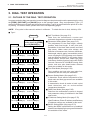
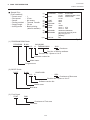
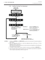
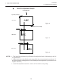
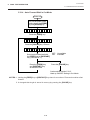
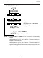
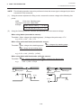
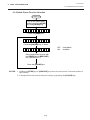
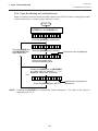
5.1 OUTLINE OF THE DIAG. TEST OPERATION
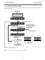
In system mode the diag. test operation is used to diagnose the printer and to set the parameters by using
the [FEED], [RESTART] and [PAUSE] keys on the operation panel. Diag. test operation (Type I) is
started from the power off state and the parameter setting (Type II) is started while the printer is on-line
or printing. For further details, please refer to the corresponding pages.
NOTE: Every size in this manual is written in millimeter. To obtain the size in inch, divide by 25.4.
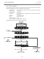
■ Type I
Power off
Turn on the power while
holding down the [FEED]
key and [PAUSE] key.
Press the [RESTART] key.
< 1> D I AG .
V1 . O A
Press the [RESTART] key.
Press the [FEED] key.
< 2> P A RA ME TE R
Press the [RESTART] key.
< 3> T E ST
< 4> S E NS OR
Press the [RESTART] key.
Press the [FEED] key.
A D J.
Press the [FEED] key.
CL EA R
Press the [RESTART] key.
< 6> I P
Press the [FEED] key.
P RI N T
Press the [RESTART] key.
< 5> R A M
S E T
Press the [FEED] key.
A DD RE S S
Press the [RESTART] key.
< 7> B A SI C
Press the [FEED] key.
■ Self Test Mode (See page 5-3)
Data from the maintenance counter and
automatic diagnosis are printed on the media.
■ Parameter Setting Mode (See page 5-15)
Fine adjustment of the feed length, cut/strip
position, back feed length, X axis, print tone,
thresholds of the black mark sensor and feed
gap sensor, ribbon motor drive voltage, and
selection of character code, font zero, baud rate,
data length, stop bit, parity, transmission control
mode, language of LCD message, auto forward
wait and head up ON/OFF in cut mode, ribbon
saving module, control code, ribbon type, strip
wait status, feed key function, kanji code, EURO
font cod, Centronics I/F ACK/BUSY timing, Web
printer, and auto print head broken element
check are available in this mode.
■ Test Print Mode (See page 5-53)
Print condition and test print type (slant line,
characters and bar code) are selectable.
■ Sensor Setting Mode (See page 5-60)
A thermistor check and the adjustment of the
black mark and feed gap sensors are available
in this mode.
A transmission check is made to both a print
head thermistor and an environmental
temperature thermistor.
■ RAM Clear Mode (See page 5-65)
Data from the maintenance counter is cleared
and parameter setting is initialized in the RAM
clear mode.
■ IP Address Setting Mode (See page 5-70)
Host IP address, Printer IP address, and Gateway
IP address settings are available in this mode.
■ BASIC Setting Mode (See page 5-72)
Setting the BASIC specification to be enabled/
disabled and displaying the program file/data file
are available in this mode.
5-1
EO18-33004
(Revision Date: Mar. 11, 2000)
5.1 OUTLINE OF THE DIAG. TEST OPERATION
5. DIAG. TEST OPERATION
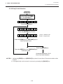
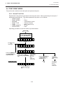
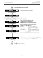
In system mode the [FEED], [RESTART] and [PAUSE] keys function as described below.
Key Name
[FEED] key
[RESTART] key
[PAUSE] key
Function
Used to start the system mode as a [PAUSE] key does. Used to select the
parameter mode or to fine adjust the parameters in the negative direction ( - ).
Used to select the parameter mode or to fine adjust the parameters in the
positive direction (+)
Used to start the system mode as a [FEED] key does and to select the parameter
mode. Used as an enter key.
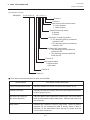
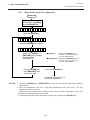
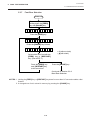
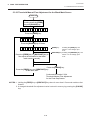
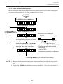
■ Type II
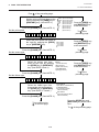
The parameter setting such as feed length fine adjustment or cut/strip position fine adjustment can be
changed while the printer is on-line or printing. Pressing the [PAUSE] key causes the printer to enter
parameter setting mode. Reset mode is provided for this procedure to cancel the steps which follow the
[PAUSE] key without turning the power off.
Power On
O N > L I N E .
V 1 . O A
The printer is in stand-by or printing.
Press the [PAUSE] key.
P A U S E R A M E T E R
S E T
The printer enters the pause state.
Press and hold the [RESTART] key for at least 3 seconds.
< 1 > R E S E T P R I N T
A reset menu is displayed.
Press the [RESTART] key twice.
< 3 > D U M P P M O D E J .
A dump mode menu is displayed.
Press the [PAUSE] key.
B U F F E R E R S - 2 3 2 C
Select receive buffer with the [FEED] key or [RESTART] key.
RS-232C:
NETWORK:
CENTRO:
BASIC 1:
BASIC 2:
Press the [PAUSE] key.
P R I N T I N G . . . D J .
RS-232C receive buffer
Network I/F receive buffer
Centronics I/F receive buffer
BASIC Interpreter
(I/F
Interpreter buffer)
BASIC Interpreter
(Interpreter
Printer Buffer)
Receive buffer data is printed. After that,
the display restores the dump mode menu.
NOTES: 1. Pressing the [PAUSE] key during printing causes the printer to pause printing and
show the number of remaining media.
2. If the [RESTART] key is released within 3 seconds, the printer will resume printing
because the [RESTART] key is activated.
3. Since the reset is performed when terminating this mode, the printer cancels the
remaining media and returns to on-line mode. This reset will not clear the changed
parameter settings.
5-2
EO18-33004
(Revision Date: Jan. 12, 2001)
5.2 SELF TEST MODE
5. DIAG. TEST OPERATION
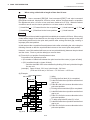
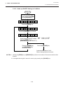
5.2 SELF TEST MODE
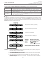
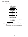
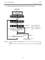
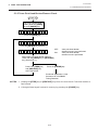
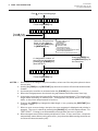
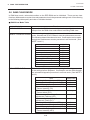
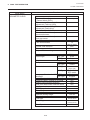
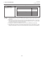
In self test mode the printer status is printed in two types of sample print.
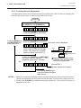
5.2.1 Maintenance Counter and Parameter Printing
The data from 1 to 50 on a sample print is printed. This data is the printer status and the
value set in the parameter setting mode.
Power off
Turn on the power while
holding down the [FEED]
key and [PAUSE] key.
< 1> D I AG .
V1 . O A
Continued on Section 5.2.2
Automatic Diagnostics Printing.
Press the [PAUSE] key.
R IB B O N
Press the [PAUSE] key.
T RA N S.
Select the ribbon type from those
at the right by pressing the
[FEED] key or [RESTART] key.
Press the [PAUSE] key.
M AI N T EN AN CE
NO RIBBON (No ribbon : Thermal direct)
TRANSMISSIVE
(Transmissive ribbon : Thermal transfer)
NO TRANS.
(Non-transmissive ribbon : Thermal transfer)
CONT
Press the [PAUSE] key.
C HE C K IN G
&
P RI N T
The printer is checking or printing
the status
The result of the self test
is printed. After printing,
the initial display will be
shown.
NOTES: 1. If the maintenance counter printing results in an error, the printer will display the error
message and stop printing. The error status can be cleared by the [PAUSE] key,
however, the display will return to the initial display “<1> DIAG. V1.0A”. Printing is not
automatically resumed after the error is cleared.
2. Both label and tag paper can be used for printing.
5-3
EO18-33004
(Revision Date: Dec. 14, 2001)
5.2 SELF TEST MODE
5. DIAG. TEST OPERATION
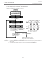
■ Sample Print
[Print Condition]
• Preset count
• Print speed
• Sensor
• Printing method
• Supply length
• Issuing mode
:
:
:
:
:
:
1
5"/sec.
No sensor
Thermal transfer
140 mm
Batch printing
(without rewinder)
(1)
(2)
(3)
(4)
(5)
(6)
(7)
TL FEED
FEED
PRINT
CUT
HEAD U/D
RIBBON
SOLENOID
1.1 km
1.1 km
0.5 km
96
32
3h
0h
(8)
(9)
(10)
232C ERR
SYS ERR
PW FAIL
255
0
0
(11)
(12)
THRESHOLD (R)
THRESHOLD (L)
1.0 V
0.7 V
(13)
(14)
(15)
(16)
(17)
(18)
(19)
(20)
(21)
(22)
(23)
(24)
(25)
(26)
(27)
(28)
(29)
(30)
(31)
(32)
(33)
(34)
(35)
(36)
(37)
(38)
(39)
FONT [PC-850]
CODE [AUTO]
RIBBON
STATUS
SPEED
DATA LENG
STOP BIT
PARITY
CONTROL
MESSAGE
FORWARD WAIT
HEAD UP CUT
RIBBON SAVE
FEED KEY
KANJI
EURO CODE
AUTO HD CHK
WEB PRINTER
HOST IP ADDR
PRTR IP ADDR
GATE IP ADDR
SUBNET MASK
TTF AREA
EXT CHR AREA
BASIC AREA
PC SAVE AREA
SOCKET PORT
[0]
[PC]
FEED
CUT
BACK
TONE (T)
TONE (D)
RBN (FW)
RBN (BK)
[KEY]
FEED
CUT
BACK
TONE (T)
TONE (D)
RBN (FW)
RBN (BK)
X ADJ.
[TRANS]
[1]
[9600]
[8]
[1]
[EVEN]
[XON+READY AUTO]
[ENGLISH]
[OFF]
[OFF]
[ON]
[FEED]
[TYPE1]
[B0]
[OFF]
[OFF]
[192.168.010.010]
[192.168.010.020]
[000.000.000.000]
[255.255.255.000]
[704 KB]
[128 KB]
[64 KB]
[64 KB]
[OFF] [08000]
5-4
+2.0 mm
+0.0 mm
+0.0 mm
+0 step
+0 step
-10
+0
(40)
(41)
(42)
(43)
(44)
(45)
(46)
+0.0 mm
+1.0 mm
+0.0 mm
+0 step
+0 step
-8
+0
+0.0 mm
(47)
(48)
(49)
(50)
(51)
(52)
(53)
(54)
Fig. 5-1
EO18-33004
(Revision Date: Mar. 11, 2000)
5.2 SELF TEST MODE
5. DIAG. TEST OPERATION
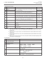
1) Maintenance Counter
#
Item
(1) Total media distance
covered
(2) Media distance covered
(3) Print distance
(4)
(5)
(6)
(7)
Count Condition
Range
Counted when the feed motor drives to feed, print and issue the 0.0 to 3200.0
media. (Counted also during ribbon save operation and back
km
feed.) [See NOTE 2.]
0.0 to 200.0 km
Counted while printing. (Feeding and issuing media, and ribbon 0.0 to 200.0 km
saving operation are not counted.) [See NOTE 2.]
Counts every cut. [See NOTE 3.]
Cut count
0 to 1000000
times
Head up and down count Counts every up and down of the print head using the solenoid 0 to 2000000
for ribbon save operation. (Up+Down=1 count) [See NOTE 3.]
times
Ribbon motor driving time Counts when the ribbon motor drives to feed, print and issue the
0 to 2000
media. (The driving time is not counted during ribbon saving
hours
operation, but is during back feed.) [See NOTE 4.]
Counted during ribbon saving operation. [See NOTE 4.]
Solenoid driving time
0 to 1000
hours
(8) RS-232C hardware error Counted when a parity, overrun or framing error occurs. [See 0 to 255 times
NOTE 5.]
count
(9) System error count
Counted when a zero-dividing error occurs or undefined command 0 to 15 times
is retrieved.
(10) Momentary power failure Counts the number of times the power restores while the CPU is 0 to 15 times
busy after reset.
count
NOTES: 1. Item from (2) through (10) are initialized to “0” after RAM clear.
2. If the distance is 5.5 m or less, it is rounded down and no data is added to the memory
at power off.
3. If the count is 31 counts or less, it is rounded down and no data is added to the memory
at power off.
4. If the driving time is 27 sec. or less, it is rounded down and no data is added to the memory
at power off.
5. When a sent command results in an error, the same number as the data capacity of the
command is counted by byte.
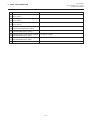
2) Parameters
#
Item
(11) Threshold manual fine adjustment for
the black mark sensor
(12) Threshold manual fine adjustment for
the feed gap sensor
(13) Character
Font zero
(14) Control code
(15) Ribbon type
Contents
0.0V to 4.0V
0.0V to 4.0V
PC-850: PC-851
PC-1252
LATIN9
PC-852: PC-855
PC-1253
Arabic
PC-857: PC-1250
PC-1254
PC-8:
PC-1251
PC-1257
0: No slash used.
0: Slash used.
AUTO:
Automatic selection
ESC LF NUL: ESC LF NUL mode
{}:
Mainframe mode
1B 1C 1D:Manual
TRANS.:
Transmissive ribbon
NON TRANS.: Non-transmissive ribbon
5-5
EO18-33004
(Revision Date: Dec. 14, 2001)
5.2 SELF TEST MODE
5. DIAG. TEST OPERATION
#
(16) Status
(17)
(18)
(19)
(20)
(21)
(22)
(23)
(24)
(25)
(26)
(27)
(28)
(29)
(30)
(31)
(32)
(33)
(34)
(35)
(36)
(37)
(38)
(39)
Item
Contents
1:
Strip wait status is not sent to the PC.
2:
Strip wait status is sent to the PC.
Baud rate
2400:
2400 bps
4800:
4800 bps
9600:
9600 bps
19200: 19200 bps
38400: 38400 bps
Data length
7:
7 bits
8:
8 bits
Stop bit
1:
1 bit
2:
2 bits
Parity
NONE: None
ODD:
ODD
EVEN: EVEN
Transmission control code
XON/XOFF:
XON/XOFF
READY/BUSY:
READY/BUSY (DTR)
XON+READY AUTO:
XON/XOFF+READY/BUSY (DTR)
XON/XOFF AUTO:
XON/XOFF
READY/BUSY RTS:
RTS
Language selection for LCD message ENGLISH:
English
GERMAN:
German
FRENCH:
French
DUTCH:
Dutch
SPANISH:
Spanish
JAPANESE:
Japanese
ITALIAN:
Italian
Auto forward wait in cut mode
ON:
Available
OFF:
Unavailable
Head up in cut mode
ON:
Available
OFF:
Unavailable
Ribbon saving module
ON:
Available
OFF:
Unavailable
Feed key function
FEED: feeds one label
PRINT: prints image buffer on one label
Kanji code type
TYPE 1: Windows code
(Not supported QQ/QP models)
TYPE 2: Original code
Euro font code
20H to FFH
Auto print head broken element check ON:
Available
OFF:
Unavailable
Web printer function
ON:
Available
OFF:
Unavailable
Host IP address
***.***.***.***
Printer IP address
***.***.***.***
Gateway IP address
***.***.***.***
Subnet mask
***.***.***.***
True type font registration area size
0 KB to 896 KB (units of 64 KB)
External character registration area size 0 KB to 896 KB (units of 64 KB)
BASIC file store area size
0 KB to 896 KB (units of 64 KB)
PC saving area size
0 KB to 896 KB (units of 64 KB)
Socket port number
ON:
Available
OFF:
Unabailable
Port No. 0 ~ 65535
5-6
EO18-33004
(Revision Date: Dec. 14, 2001)
5.2 SELF TEST MODE
5. DIAG. TEST OPERATION
#
(40)
(47)
(41)
(48)
(42)
(49)
(43)
(50)
(44)
(51)
(45)
(52)
(46)
(53)
(54)
Item
Feed length fine adjustment
(PC), (KEY)
Cut/Strip position fine adjustment
(PC), (KEY)
Back feed length fine adjustment
(PC), (KEY)
Print tone fine adjustment
(Thermal transfer) (PC), (KEY)
Print tone fine adjustment
(Thermal direct) (PC), (KEY)
Ribbon take-up motor driving voltage
fine adjustment (PC), (KEY)
Ribbon feed motor driving voltage
fine adjustment (PC), (KEY)
X axis fine adjustment
Contents
-50.0 mm to +50.0 mm
-50.0 mm to +50.0 mm
-9.9 mm to +9.9 mm
-10 step to +10 step
-10 step to +10 step
-15 step to +0 step
-15 step to +0 step
-99.5 mm to +99.5 mm
5-7
EO18-33004
5. DIAG. TEST OPERATION
5.2 SELF TEST MODE
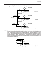
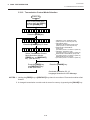
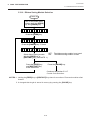
5.2.2 Automatic Diagnostic Printing
The data from 1 to 9 on a sample print is printed.
Power off
Turn on the power while
holding down the [FEED]
key and [PAUSE] key.
< 1> DI AG .
V1 . O A
Press the [PAUSE] key.
R IB BO N
T RA N S.
Select the ribbon type from those
at the right by pressing the
[FEED] key or [RESTART] key.
Press the [PAUSE] key.
NO RIBBON (No ribbon : Thermal direct)
TRANSMISSIVE
(Transmissive ribbon : Thermal transfer)
NO TRANS.
(Non-transmissive ribbon : Thermal transfer)
Press the [FEED] key.
A UT O
DI AG NOS T I C
Press the [PAUSE] key.
C HE CK IN G
&
P RI N T
The printer is checking or printing
the status
The result of the self test
is printed. After printing,
the initial display will be
shown.
NOTES: 1. If the automatic diagnosis printing results in an error, the printer will display the error
message and stop printing. The error status can be cleared by the [PAUSE] key,
however, the display will return to the initial display "<1> DIAG. V1.0A". Printing is not
automatically resumed.
2. Both label and tag paper can be used for printing.
5-8
EO18-33004
5. DIAG. TEST OPERATION
5.2 SELF TEST MODE
■ Sample Print
[Print condition]
• Preset count
• Print speed
• Sensor
• Printing method
• Supply length
• Issuing mode
:
:
:
:
:
:
1
5"/sec.
No sensor
Thermal Transfer
59 mm
Batch printing
(without rewinder)
(1)
PROGRAM
(2)
BOOT
(3)
(4)
(5)
(6)
(7)
FONT
KANJI
EEPROM
DRAM
CARD
(8)
(9)
SENSOR1
SENSOR2
(10)
EXP.I/O
B-480
04JUN1999
V1.0A
FMRM0034806: 1A00
B-480
16NOV1998
V1.0A
FMRM0034806: 8500
5600
8900
OK
16MB
SLOT 1 ATA
SLOT 2 LAN
00000000,00000000
[H] 20°C [A] 22°C [S] 25°C
[R] 4.2V [T] 2.5V
[RANK]7
NG
Fig. 5-2
(1) PROGRAM ROM Check
PROGRAM
B-480
V1.0
04JUN1999
A FMRM0034806
:
1A00
Checksum
Part No. of ROM or software
Revision No.: Space or A to Z
Software version No.
Model name
Program area
(2) BOOT Check
BOOT
B-480
V1.0
16NOV1998
A
:
8500
Checksum of Boot area
Revision No.: Space or A to Z
Software version No.
Model name
Boot area
(3) Font Check
FONT
5600
Checksum of Font area
Font area
5-9
EO18-33004
(Revision Date: Sep. 24 '99)
5.2 SELF TEST MODE
5. DIAG. TEST OPERATION
(4) Kanji Check
KANJI
9D00
Checksum of BITMAP Kanji ROM
Kanji area
(5) EEPROM Check
EEPROM
OK
OK: Data in the check area can be properly read/written.
NG: Data in the check area cannot be properly read/written.
EEPROM (Backup Memory)
(6) DRAM Check
DRAM
16MB
Capacity of DRAM
System/Painting memory
(7) PC card Check
CARD
SLOT 1
SLOT 2
ATA
LAN
ATA:
LAN:
FSH:
NO:
ATA card is inserted.
LAN card is inserted.
Flash memory card is inserted.
Unformatted ATA card/Flash memory
card or no card is inserted.
Slot
PCMCIACard
NOTES: 1. Software version No., part No. of ROM and checksum vary according to the software
version of PROGRAM ROM.
2. The last two digits of the checksum are usually 0.
3. When the kanji ROM is not installed, the checksum becomes “0000”
4. When selecting the Diag. Test operation, pressing the [RESTART] and [FEED] keys at the same
time restores the display to the system mode menu.
5-10
EO18-33004
5. DIAG. TEST OPERATION
5.2 SELF TEST MODE
(8) Sensor 1 Check
SENSOR1
00000000, 10110011
Fixed to 1.
Fixed to 1.
Cutter home potion switch status
0: Home position
1: Other position
Rewind full sensor status
0: Normal
1: Excess
Slit sensor #1 (take-up) status
0: The detecting point is positioned
outside the slit.
1: The detecting point is positioned
inside the slit.
Slit sensor #2 (feed) status
0: The detecting point is positioned
outside the slit.
1: The detecting point is positioned
inside the slit.
Fixed to 0.
Strip sensor status
0: Without label
1: With label
Fixed to 0.
Fixed to 0.
■ Print status content description of each sensor/switch
Sensor/Switch
Print status content description
Cutter home position switch
Indicates whether the cutter is at the home position or not.
Rewind full sensor
Indicates whether the media is wound to peak capacity on the builtin take-up spool or not.
Slit sensor #1 (take-up)
Slit sensor #2 (feed)
Controls ribbon motor rotation by detecting the slit on the ribbon
take-up motor and the ribbon feed motor. Indicates the position of
the slit sensor.
Strip sensor
Indicates the existence of label in strip mode. When no label is
detected (0), the subsequent label is issued, when a label is
detected (1), the subsequent label will not be issued until the
current label is removed.
5-11
EO18-33004
5. DIAG. TEST OPERATION
5.2 SELF TEST MODE
(9) SENSOR 2 Check
SENSOR2
[H] 20°C
[A] 22°C
[S] 25°C
Heat sink temperature sensor status:
25°C, 80°C, 90°C
Environmental temperature thermistor status:
0 to 86°C
If it is undetectable, “- - °C” is printed.
Print head thermistor status: 0 ~ 86°C
[R] 4.2V
[T] 2.5V
Feed gap sensor status: 0.0 ~ 5.0V
Black mark sensor status: 0.0 ~ 5.0 V
[RANK 7]
Print head resistance rank: 0 ~ 7
Print Head Resistance Rank
Resistance Rank
0
1
2
3
4
5
6
7
Average resistance (Ω)
1409 - 1454
1361 - 1408
1314 - 1360
1266 - 1313
1219 - 1265
1171 - 1218
1124 - 1170
1076 - 1123
5-12
EO18-33004
5. DIAG. TEST OPERATION
5.2 SELF TEST MODE
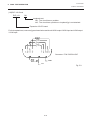
(10)EXP. I/O Check
EXP. I/O
OK
Loopback test
OK: The circuit has no problem.
NG: The circuit has a problem or loopback jig is not attached.
Expansion I/O PC board
For the loopback test, connect a jig as shown below and check HIGH output / HIGH input and LOW output
/ LOW input.
Connector: FCN-781P024-G/P
GND
Vcc
Fig. 5-3
5-13
EO18-33004
(Revision Date: Sep. 24 '99)
5.2 SELF TEST MODE
5. DIAG. TEST OPERATION
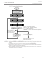
5.2.3
Head Broken Element Check
The printer automatically performs the head broken element check. The result of the head broken
element check is indicated in the display.
Power off
Turn on the power while
holding down the [FEED]
key and [PAUSE] key.
< 1> D I AG .
V 1. 0A
Press the [PAUSE] key.
Press the [FEED] key twice.
H EA D
CH EC K
Press the [PAUSE] key.
C HE C K IN G
N OR MA L
EN D
H EA D
ER RO R
(See NOTE 1 and 2.)
Press the [PAUSE] key.
NOTES: 1. If the head broken element check results in ‘HEAD ERROR’, the print head must be
replaced after referring to Section 2.8 Replacing the Print Head.
2. After replacing the print head, clear the maintenance counter as described in Section
5.6.1 and perform a test print in Section 5.4 TEST PRINT MODE.
5-14
EO18-33004
5. DIAG. TEST OPERATION
5.3 PARAMETER SETTING MODE
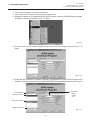
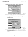
5.3 PARAMETER SETTING MODE
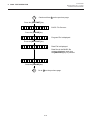
The following items are set in the parameter setting mode. The values set in this mode are printed on
the sample print of the maintenance counter. Setting procedure and functions are provided below.
Power off
Press the [PAUSE] key.
Turn on the power while
holding down the [FEED]
key and [PAUSE] key.
F OR W AR DL WAI T
0O FF
Press the [PAUSE] key.
< 1> DI AG .O STI C
V1 . O A
H E A D I U PO C U T
TYO FF
Press the [FEED] key.
Press the [PAUSE] key.
< 2> P A RA ME TE R
R IB B O NO S A V E
S E T
Press the [PAUSE] key.
Press the [PAUSE] key.
F EE D
AD J. SS
+ 0. 0 m m
C OD E
A DJ .S S
+ 0. 0 m m
R IB B O N
AD J. + 0. 0 m m
R BN BA DJ .< FW >
A DJ US T
+ 0. 0 m m
R BN B A DJ A< BK>
Press the [PAUSE] key.
T ON E
AD J. SS
<T >
AD J. SS
<D >
+ 0
S TA T U S
CO DE
+ 0
S TA C KE RL D
P C- 8 5 0
FO NT
O FF
F EE DU KE YY PE
T HR E SH OL D
FE E D
< T > < < < 1. 0V
Press the [PAUSE] key.
Press the [PAUSE] key.
9 6 00 b p s
T HR E SH OL D
< T > < < < 0. 7V
Press the [PAUSE] key.
Press the [PAUSE] key.
D AT AO LE NG .
R
Press the [PAUSE] key.
0
S PE ED
1
Press the [PAUSE] key.
Press the [PAUSE] key.
Z ER O
T Y PE
Press the [PAUSE] key.
Press the [PAUSE] key.
F ON T
+O
Press the [PAUSE] key.
Press the [PAUSE] key.
T ON E
+O
Press the [PAUSE] key.
Press the [PAUSE] key.
X
T RA N S .
Press the [PAUSE] key.
Press the [PAUSE] key.
B AC KA AD J.
A U T O
Press the [PAUSE] key.
Press the [PAUSE] key.
C UT
T YP ON
8 8b i t s
K AN J I
CO D E
TY P E1
Press the [PAUSE] key.
Press the [PAUSE] key.
S TO PO BIT D D
D DD D D 1 b it
E UR O
C OD E
B 0H
Press the [PAUSE] key.
Press the [PAUSE] key.
A UT OT HD
P AR IT Y
A D J
C HK
HA K> E O FF
< BA K> E V EN
Press the [PAUSE] key.
Press the [PAUSE] key.
X ON +R EAD Y PE
E EA U T O
A CK / B USY Y TYP E
T TY P E 1
Press the [PAUSE] key.
Press the [PAUSE] key.
W EB E P R IN T ER
L CD E SH OL D
R
E N G L O FF
E N G L I SH
Press the [PAUSE] key.
5-15
EO18-33004
5. DIAG. TEST OPERATION
5.3 PARAMETER SETTING MODE
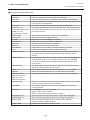
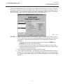
■ Parameter Setting Mode Table
Mode Name
FEED ADJ.
CUT ADJ.
BACK ADJ.
X ADJUST
TONE ADJ. <T>
(Thermal transfer printing)
TONE ADJ. <D>
(Thermal direct printing)
FONT CODE
ZERO FONT
SPEED
DATA LENG.
STOP BIT
PARIITY
XON+READY
LCD
FORWARD WAIT
HEAD UP CUT
RIBBON SAVE
CODE
RIBBON
RBN ADJ <FW>
(Ribbon feed motor)
RBN ADJ <BK>
(Ribbon feed motor)
STATUS TYPE
STACKER
FEED KEY
THRESHOLD <R>
THRESHOLD <T>
KANJI CODE
EURO CODE
Function
Using this parameter the feed length is fine adjusted.
Using this parameter the cut position or strip position is fine adjusted.
Using this parameter the back feed length from the cut/strip position to the
home position is fine adjusted.
This setting is used to finely adjust print position in the X axis.
Using this parameter the print tone is fine adjusted. The longer the print
pulse width, the darker the print tone becomes. The shorter, the lighter the
print tone becomes.
The character code either PC-850 or PC-8 is selected.
The font zero either 0 or 0 is selected.
Baud rate of the serial interface is selected.
Data length of the serial interface is selected.
Stop bit of the serial interface is selected.
Parity of the serial interface is selected.
Transmission control mode of the serial interface is selected.
Language which displays LCD message is selected.
Auto forward wait in cut mode is selected. When idle for 3 seconds or
more after cutting, the printer automatically feeds the paper 10mm
forward.
Print head up in cut mode is selected. If a back feed is performed when
this parameter is ON, it is done while the print head is up. (Available
only when the ribbon saving module is installed and the ribbon save
mode is ON.)
The ribbon saving module is selected. Be sure to set this parameter to
ON when using the ribbon saving module.
The command code out of AUTO, ESC/LF/NUL, or { I } is selected.
Ribbon type either transmissive or non-transmissive is selected.
Using this parameter the torque of the ribbon motors is fine adjusted.
Whether or not the strip wait status (05H) is sent in response to the status
request command from the PC is selectable.
The stacker is selected. Be sure to set this parameter to ON when
using the stacker.
The [FEED] key function is selected.
FEED: feeds a piece of paper
PRINT: prints image buffer on a piece of paper.
The threshold of the black mark sensor is manually fine adjusted.
The threshold of the feed gap sensor is manually fine adjusted.
Kanji code either Windows code or original code is selected.
(Not supported by QQ/QP models.)
EURO code is selected from 20H to FFH.
5-16
EO18-33004
5. DIAG. TEST OPERATION
5.3 PARAMETER SETTING MODE
Mode Name
AUTO HD CHK
Function
Auto head broken element check is selected.
ON:
When the power turns ON, the auto head broken element
check is performed.
OFF: When the power turns ON, the auto head broken element check
is not performed.
Using this parameter sets the Centronics I/F ACK/BUSY timing.
The Web printer is selected.
ACK/BUSY
WEB PRINTER
5.3.1 Feed Length Fine Adjustment
Power off
Turn on the power while
holding down the [FEED]
key and [PAUSE] key.
< 1> DI AG .
V1 . O A
Press the [FEED] key.
< 2> P A RA ME TE R
S E T
Press the [PAUSE] key.
F EE D
AD J.
+ 0. 0 m m
Press the [FEED] or
[RESTART] key to adjust
the feed length.
(See NOTE 1.)
[FEED] key:
Pressing the [FEED] key one
time is a -0.5 mm change, up to
-50.0 mm. (See NOTE 2.)
[RESTART] key: Pressing the [RESTART] key one
time is a +0.5 mm change, up to
+50.0 mm. (See NOTE 2.)
Press the [PAUSE] key.
Press the [FEED] key
and [RESTART] key
at the same time.
Continued on Section 5.3.2
Cut/strip position fine adjustment.
NOTES: 1. Holding the [FEED] key or [RESTART] key down for more than 0.5 seconds enables a
fast forward.
2. Max. fine adjustment ±50.0 mm = Key fine adjustment value (±50.0 mm) + PC fine
adjustment value (±50.0 mm)
When the value reaches the maximum, the value remains unchanged even if the
subsequent fine adjustment is performed.
3. A changed feed value is stored in memory by pressing the [PAUSE] key.
5-17
EO18-33004
5. DIAG. TEST OPERATION
5.3 PARAMETER SETTING MODE
5.3.2
Cut/Strip Position Fine Adjustment
Power off
Turn on the power while
holding down the [FEED]
key and [PAUSE] key.
< 1> D I AG .
V1 . O A
Press the [FEED] key.
< 2> P A RA ME TE R
S E T
Press the [PAUSE] key twice.
C UT
A DJ .
+ 0. 0 m m
[FEED] key:
Pressing the [FEED] key one
time is a -0.5 mm change, up to
-50.0 mm. (See NOTE 2.)
[RESTART] key: Pressing the [RESTART] key one
time is a +0.5 mm change, up to
+50.0 mm. (See NOTE 2.)
Press the [FEED] or
[RESTART] key to adjust
the feed length.
(See NOTE 1.)
Press the [FEED] key
and [RESTART] key
at the same time.
Press the [PAUSE] key.
Continued on Section 5.3.3
Back feed length fine adjustment.
NOTES: 1. Holding the [FEED] key or [RESTART] key down for more than 0.5 seconds enables a
fast forward.
2. Max. fine adjustment ±50.0 mm = Key fine adjustment value (±50.0 mm) + PC fine
adjustment value (±50.0 mm)
When the value reaches the maximum, the value remains unchanged even if a subsequent
fine adjustment is performed.
3. A changed cut/strip position value is stored in memory by pressing the [PAUSE] key.
4. When using label with length of less than 38 mm, calculate the cut position fine adjustment
value using the expression provided on page 5-21.
5-18
EO18-33004
5. DIAG. TEST OPERATION
5.3 PARAMETER SETTING MODE
5.3.3
Back Feed Length Fine Adjustment
Power off
Turn on the power while
holding down the [FEED]
key and [PAUSE] key.
< 1> D I AG .
V1 . O A
Press the [FEED] key.
< 2> P A RA ME TE R
S E T
Press the [PAUSE] key 3 times.
B AC K
A DJ .
+ 0. 0 m m
[FEED] key:
Pressing the [FEED] key one
time is a -0.5 mm change, up to
-9.5 mm. (See NOTE 2.)
[RESTART] key: Pressing the [RESTART] key one
time is a +0.5 mm change, up to
+9.5 mm. (See NOTE 2.)
Press the [FEED] or
[RESTART] key to adjust
the feed length.
(See NOTE 1.)
Press the [FEED] key
and [RESTART] key
at the same time.
Press the [PAUSE] key.
Continued on Section 5.3.4
X axis fine adjustment.
NOTES: 1. Holding the [FEED] key or [RESTART] key down for more than 0.5 seconds enables a
fast forward.
2. Max. fine adjustment ±9.9 mm = Key fine adjustment value (±9.5 mm) + PC fine
adjustment value (±9.9 mm)
When the value reaches the maximum, the value remains unchanged even if the
subsequent fine adjustment is performed.
3. A changed back feed value is stored in memory by pressing the [PAUSE] key.
5-19
EO18-33004
5. DIAG. TEST OPERATION
5.3 PARAMETER SETTING MODE
Feed Length Fine Adjustment Example
+ 0.0 mm
Feed Direction
A
A
A
A
■
Fig. 5-4
- 10.0 mm
A
A
A
A
- 10 mm
Fig. 5-5
+ 10.0 mm
■
A
A
A
A
+ 10 mm
Fig. 5-6
Cut Position Fine Adjustment Example
Print Head
Cut Position
+ 0.0 mm
Tag Paper
Feed Direction
Black Mark
Platen
- 12.0 mm
Fig. 5-7
- 10 mm
Fig. 5-8
+ 12.0 mm
+ 10 mm
Fig. 5-9
5-20
EO18-33004
5. DIAG. TEST OPERATION
5.3 PARAMETER SETTING MODE
■
When using a label with a length of less than 38 mm :
Case 1
Conditions: Issue command [ESC]XS, feed command [ESC]T and eject command
[ESC]IB are received. Label pitch: 38.0 mm or less, with cut, feed gap sensor, cut position
fine adjustment value ±10 mm or less, and issue mode set to C (cut). When the above
conditions are all met, the issue operation in cut issue mode is as follows:
1 Head lifted
> 2 Forward feed to the cut position
> 3 Head lowered
5 Head lifted
> 6 Backfeed to the home position
> 7 Head lowered.
> 4 Cut
Case 2
Generally the minimum label length which is available in cut mode is 38.0 mm. When using
a label with a length of less than 38 mm, the edge of the label may be caught on the print
head during back feed to the print start position after cutting the label gap, causing a
improper print start position.
In this case set the cut position fine adjustment value after calculating the value using the
following formula so that the unprinted label returns to the correct print start position.
However, use of this method will leave one or two printed label(s) between the print head
and the cutter. Feed or print the label(s) to remove them.
(a) Formula for cut position fine adjustment value
Cut position fine adjustment value
= (the number of labels left between the print head and the cutter) x (span of label)
= (32.8 mm/label length) x (span of label)
* Omit the decimals of the value obtained by dividing 32.8 mm by the label length
for one unit.
(example) Span of label : 30.0 mm, Label length : 24.0 mm
(32.8 mm/30.0 mm) x 30.0 mm = 1 x 30.0 mm = +30.0 mm
(b) Example
Print Head Position
Cut Position
1 Idling
2 Printing the first label (A) is completed.
3 Label A is fed to the cut position and the front
gap is cut.
4 Label B is fed in the reverse direction to the
print start position.
5 Printing the second label (B) is completed.
6 Label B is fed to the cut position and the front
gap is cut.
7 Label C is fed in the reverse direction to the
print start position.
8 To take away label B, label (C) is fed.
9 Label B is fed to the cut position and the front
gap is cut.
0 Label D is fed in the reverse direction to the
print start position.
32.8 mm
A
A
A
A
A
B
B
B
A
B
B
C
C
B
C
C
D
C
D
C
Fig. 5-10
B
B
B
A
B
D
Print Satrt Position
5-21
>
EO18-33004
5. DIAG. TEST OPERATION
5.3 PARAMETER SETTING MODE
■
Strip Position Fine Adjustment Example
Print Head
Label
+ 0.0 mm
Platen
Backing Paper
Fig. 5-11
Strip Shaft
Print Head
+ 3.0 mm
+ 3.0 mm
Platen
Backing Paper
Fig. 5-12
Strip Shaft
Print Head
- 3.0 mm
- 3.0 mm
Platen
Backing Paper
Fig. 5-13
Strip Shaft
NOTE: The print stop position when printing the label in strip mode varies according to label length for
the strip mode printing stops so that the edge of the strip shaft is 4 mm from the middle of the
gap. This is because the gap length is programmed as 2 mm. When the gap length is 5 mm
or more, the effective print length should be set to the value obtained by subtracting 2 mm from
the label pitch, that is, set the gap length to 2 mm. If the print format hangs over the gap as
a result, correct the print start position. If the print stop position is improper, refer to Section 5.3.2
and make a fine adjustment.
4 mm
3 mm
Label
2 mm
Platen
Strip Shaft
Backing Paper
5-22
Fig. 5-14
EO18-33004
5. DIAG. TEST OPERATION
5.3 PARAMETER SETTING MODE
+ 0.0 mm
Feed Direction
Back Feed Length Fine Adjustment Example
A
A
A
A
■
Fig. 5-15
Print start position
-3.0 mm
Fig. 5-16
-3.0 mm
A
A
A
A
+3.0 mm
A
A
A
A
+3.0 mm
5-23
Fig. 5-17
EO18-33004
5. DIAG. TEST OPERATION
5.3 PARAMETER SETTING MODE
5.3.4
X Axis Fine Adjustment
Power off
Turn on the power while
holding down the [FEED]
key and [PAUSE] key.
< 1> D I AG .
V1 . O A
Press the [FEED] key.
< 2> P A RA ME TE R
S E T
Press the [PAUSE] key 4 times.
X
A D J US T
+ 0. 0 m m
[FEED] key:
Pressing the [FEED] key one
time is a -0.5 mm change, up to
-99.5 mm. (See NOTE 2.)
[RESTART] key: Pressing the [RESTART] key one
time is a +0.5 mm change, up to
+99.5 mm. (See NOTE 2.)
Press the [FEED] or
[RESTART] key to fine
adjust the print position
along the X axis.
(See NOTE 1.)
Press the [PAUSE] key.
Press the [FEED] key
and [RESTART] key
at the same time.
Continued on Section 5.3.5
Print tone fine adjustment.
NOTES: 1. Holding the [FEED] key or [RESTART] key down for more than 0.5 seconds enables a
fast forward.
2. Max. fine adjustment ±99.5 mm = X axis value
When the value reaches the maximum, the value remains unchanged even if the
subsequent fine adjustment is performed.
3. A changed X axis is stored in memory by pressing the [PAUSE] key.
5-24
EO18-33004
5. DIAG. TEST OPERATION
5.3 PARAMETER SETTING MODE
■
X Axis Fine Adjustment Example
Feed direction
Top down printing
X
Y
ABC
+ 0.0 mm
Y
Fig. 5-18
X
Bottom first printing
-50.0 mm
-50.0 mm
ABC
Fig. 5-19
+ 50.0 mm
+50.0 mm
ABC
Fig. 5-20
NOTES: 4. The X axis fine adjustment is performed to fine adjust the X axis of the drawing in the left
or right direction.
5. Adjust the X axis in the effective print range. (After the value reaches the coordinate “0”,
the value remains unchanged even if the subsequent fine adjustment is performed in the
negative direction.)
6. X axis fine adjustment cannot be used in self test mode or test printing.
5-25
EO18-33004
5. DIAG. TEST OPERATION
5.3 PARAMETER SETTING MODE
5.3.5
Print Tone Fine Adjustment
Power off
Turn on the power while
holding down the [FEED]
key and [PAUSE] key.
< 1> D I AG .
V1 . O A
Press the [FEED] key.
< 2> P A RA ME TE R
S E T
Press the [PAUSE] key 5 times.
T ON E
AD J. <T >
(Thermal transfer printing fine
adjustment)
+ 0
[FEED] key:
Pressing the [FEED] key one
time is a -1 steps change, up to
-10 steps. (See NOTE 2.)
[RESTART] key: Pressing the [RESTART] key one
time is a +1 steps change, up to
+10 steps. (See NOTE 2.)
Press the [FEED] or
[RESTART] key to adjust
the feed length.
(See NOTE 1.)
Press the [PAUSE] key.
(See NOTE 3.)
T ON E
AD J. <D >
(Thermal transfer printing fine
adjustment)
+ 0
[FEED] key:
Pressing the [FEED] key one
time is a -1 steps change, up to
-10 steps. (See NOTE 2.)
[RESTART] key: Pressing the [RESTART] key one
time is a +1 steps change, up to
+10 steps. (See NOTE 2.)
Press the [FEED] or
[RESTART] key to fine
adjust the print tone.
(See NOTE 1.)
Press the [PAUSE] key .
Press the [FEED] key
and [RESTART] key
at the same time.
Continued on Section 5.3.6
Character code selection.
NOTES: 1. Holding the [FEED] key or [RESTART] key down for more than 0.5 seconds enables a fast
forward.
2. A changed print tone value is stored in memory by pressing the [PAUSE] key.
3. Fine adjustment value equals to the sum of the values set by the PC command and system
mode (key operation) and each max. value is ±10 step. However, the upper limit of the
adjustment value is decided according to the print speed to protect the print head. If the set
value exceeds the following upper limit, it is automatically corrected to the proper value.
Print Speed
3” / sec.
4” / sec.
5” / sec.
8” / sec.
Thermal Transfer
+10 step
+5 step
+2 step
5-26
Thermal Direct
+ 10 step
+ 2 step
+ 5 step
+ 2 step
EO18-33004
5. DIAG. TEST OPERATION
5.3 PARAMETER SETTING MODE
5.3.6
Character Code Selection
Power off
Turn on the power while
holding down the [FEED]
key and [PAUSE] key.
< 1> DI AG .
V1. OA
Press the [FEED] key.
< 2> PA RA ME TER
S ET
Press the [PAUSE] key 7 times.
F ON T
CO DE
PC-8 50
Select either chracter code with
the [FEED] key or [RESTART]
Key.(See NOTE1.)
Press the [FEED] key
and [RESTART] key
at the same time.
PC-850
PC-852
PC-857
PC-8
Press the [PAUSE] key .
Continued on Section 5.3.7
Font zero selection.
NOTES: 1. Holding the [FEED] key or [RESTART] key down for more than 0.5 seconds enables a fast
forward.
2. A changed font code is stored in memory by pressing the [PAUSE] key.
5-27
EO18-33004
5. DIAG. TEST OPERATION
5.3 PARAMETER SETTING MODE
5.3.7
Font Zero Selection
Power off
Turn on the power while
holding down the [FEED]
key and [PAUSE] key.
< 1> DI AG .
V1. OA
Press the [FEED] key.
< 2> PA RA ME TER
S ET
Press the [PAUSE] key 8 times.
Z ER O
FO NT
0
Select either zero font with the
[FEED] key or [RESTART]
key. (See NOTE 1.)
Press the [FEED] key
and [RESTART] key
at the same time.
0 (without slash)
0 (with slash)
Press the [PAUSE] key .
Continued on Section 5.3.8
Baud Rate Selection
NOTES: 1. Holding the [FEED] key or [RESTART] key down for more than 0.5 seconds enables a fast
forward.
2. A changed zero font is stored in memory by pressing the [PAUSE] key.
5-28
EO18-33004
5. DIAG. TEST OPERATION
5.3 PARAMETER SETTING MODE
5.3.8
Baud Rate Selection
Power off
Turn on the power while
holding down the [FEED]
key and [PAUSE] key.
< 1> DI AG .
V 1. 1A
Press the [FEED] key.
< 2> PA RA ME TER
S ET
Press the [PAUSE] key 9 times.
S P EED
960 0B PS
Select baud rate with the
[FEED] key or [RESTART]
key. (See NOTE 1.)
Press the [FEED] key
and [RESTART] key
at the same time.
38400 BPS
19200 BPS
9600 BPS
4800 BPS
2400 BPS
Press the [PAUSE] key.
Continued on Section 5.3.9
Data Length Selection.
NOTES: 1. Holding the [FEED] key or [RESTART] key down for more than 0.5 seconds enables a fast
forward.
2. A changed baud rate is stored in memory by pressing the [PAUSE] key.
5-29
EO18-33004
5. DIAG. TEST OPERATION
5.3 PARAMETER SETTING MODE
5.3.9
Data Length Selection
Power off
Turn on the power while
holding down the [FEED]
key and [PAUSE] key.
< 1> DI AG .
V 1. 1A
Press the [FEED] key.
< 2> PA RA ME TER
S ET
Press the [PAUSE] key 10 times.
D A TA
LE NG .
8 bi ts
Select data length with the
[FEED] key or [RESTART]
key. (See NOTE 1.)
Press the [FEED] key
and [RESTART] key
at the same time.
8 bits
7 bit
Press the [PAUSE] key.
Continued on Section 5.3.10
Stop Bit Selection.
NOTES: 1. Holding the [FEED] key or [RESTART] key down for more than 0.5 seconds enables a fast
forward.
2. A changed data length is stored in memory by pressing the [PAUSE] key.
5-30
EO18-33004
5. DIAG. TEST OPERATION
5.3 PARAMETER SETTING MODE
5.3.10 Stop Bit Selection
Power off
Turn on the power while
holding down the [FEED]
key and [PAUSE] key.
< 1> DI AG .
V 1. 0A
Press the [FEED] key.
< 2> PA RA ME TER
S ET
Press the [PAUSE] key 11 times.
S T OP
BI TG .
8 1b it
Select data length with the
[FEED] key or [RESTART]
key. (See NOTE 1.)
Press the [FEED] key
and [RESTART] key
at the same time.
2 bits
1 bit
Press the [PAUSE] key.
Continued on Section 5.3.11
Parity Selection.
NOTES: 1. Holding the [FEED] key or [RESTART] key down for more than 0.5 seconds enables a fast
forward.
2. A changed data length is stored in memory by pressing the [PAUSE] key.
5-31
EO18-33004
5. DIAG. TEST OPERATION
5.3 PARAMETER SETTING MODE
5.3.11 Parity Selection
Power off
Turn on the power while
holding down the [FEED]
key and [PAUSE] key.
< 1> DI AG .
V 1. 1A
Press the [FEED] key.
< 2> PA RA ME TER
S ET
Press the [PAUSE] key 12 times.
P A RIT Y
EV EN
Select parity with the
[FEED] key or [RESTART]
key. (See NOTE 1.)
Press the [FEED] key
and [RESTART] key
at the same time.
EVEN
ODD
NONE
Press the [PAUSE] key.
Continued on Section 5.3.12
Transmission Control Mode
Selection.
NOTES: 1. Holding the [FEED] key or [RESTART] key down for more than 0.5 seconds enables a fast
forward.
2. A changed parity is stored in memory by pressing the [PAUSE] key.
5-32
EO18-33004
5. DIAG. TEST OPERATION
5.3 PARAMETER SETTING MODE
5.3.12 Transmission Control Mode Selection
Power off
Turn on the power while
holding down the [FEED]
key and [PAUSE] key.
< 1> DI AG .
V 1. 1A
Press the [FEED] key.
< 2> PA RA ME TER
S ET
Press the [PAUSE] key 13 times.
X O N+R EA DY
AU TO
Select Transmiddion Control
Mode Selection with the
[FEED] key or [RESTART]
key. (See NOTE 1.)
Press the [FEED] key
and [RESTART] key
at the same time.
XON/XOFF AUTO: XON/XOFF mode
(XON at power on, XOFF at power off)
XON+READY AUTO:
XON/XOFF+READY/BUSY (DTR) mode
(XON at power on, XOFF at power off)
READY/BUSY: READY/BUSY
(DTR) mode
(No XON at power on nor XOFF at power off)
XON/XOFF: XON/XOFF mode
(No XON at power on nor XOFF at power off)
READY/BUSY: READY/BUSY (RTS) mode
(No XON at power on nor XOFF at power off)
READY/BUSY RTS: RTS mode
(No XON at power on nor XOFF at power off)
Press the [PAUSE] key.
Continued on Section 5.3.13
Language Selection for LCD Message.
NOTES: 1. Holding the [FEED] key or [RESTART] key down for more than 0.5 seconds enables a fast
forward.
2. A changed transmission control mode is stored in memory by pressing the [PAUSE] key.
5-33
EO18-33004
5. DIAG. TEST OPERATION
5.3 PARAMETER SETTING MODE
5.3.13 Language Selection for LCD Message
Power off
Turn on the power while
holding down the [FEED]
key and [PAUSE] key.
< 1> DI AG .
V 1. 1A
Press the [PAUSE] key.
< 2> PA RA ME TER
S ET
Press the [PAUSE] key 14 times.
M E SSA GE
EN G LI S H
Slect a language to display the
LCD maessage with the [FEED]
key or [RESTART] key.
(See NOTE 1.)
Press the [FEED] key
and [RESTART] key at
the same time.
ENGLISH
GERMAN
FRENCH
DUTCH
SPANISH
JAPANESE
ITALIAN
Press the [PAUSE] key.
Continued on Section
5.3.14 Auto Forward Wait
in Cut Mode
NOTES: 1. Holding the [FEED] key or [RESTART] key down for more than 0.5 seconds enables a fast
forward.
2. A changed language is stored in memory by pressing the [PAUSE] key.
3. A changed language is not cleared by a parameter clear.
5-34
EO18-33004
5. DIAG. TEST OPERATION
5.3 PARAMETER SETTING MODE
5.3.14 Auto Forward Wait in Cut Mode
Power off
Turn on the power while
holding down the [FEED]
key and [PAUSE] key.
< 1> D I AG .
V 1. 0 A
Press the [FEED] key.
< 2> P A RA ME TE R
S E T
Press the [PAUSE] key 15 times.
F O RW A RD TW AI T 1O F F
Select auto forward wait with
the [FEED] key or [RESTART]
key. (See NOTE 1.)
Press the [FEED] key
and [RESTART] key
at the same time.
OFF: Unavailable
ON: Available
Press the [PAUSE] key.
Continued on Section 5.3.15
Head up ON/OFF Setting in Cut Mode.
NOTES: 1. Holding the [FEED] key or [RESTART] key down for more than 0.5 seconds enables a fast
forward.
2. A changed data length is stored in memory by pressing the [PAUSE] key.
5-35
EO18-33004
5. DIAG. TEST OPERATION
5.3 PARAMETER SETTING MODE
5.3.15 Head up ON/OFF Setting in Cut Mode
Power off
Turn on the power while
holding down the [FEED]
key and [PAUSE] key.
< 1> DI AG .
V 1. 0A
Press the [FEED] key.
< 2> PA RA ME TER
S ET
Press the [PAUSE] key 16 times.
H E ADA UP TC UTT 1O FF
OFF: Head up is OFF
Select head up ON/OFF setting ON: Head up is ON
with the [FEED] key or
[RESTART] key. (See NOTE 1.)
Press the [FEED] key
and [RESTART] key
at the same time.
Press the [PAUSE] key.
Continued on Section 5.3.16
Ribbon Saving Module Selection.
NOTES: 1. Holding the [FEED] key or [RESTART] key down for more than 0.5 seconds enables a fast
forward.
2. A changed data length is stored in memory by pressing the [PAUSE] key.
5-36
EO18-33004
5. DIAG. TEST OPERATION
5.3 PARAMETER SETTING MODE
5.3.16 Ribbon Saving Module Selection
Power off
Turn on the power while
holding down the [FEED]
key and [PAUSE] key.
< 1> DI AG .
V 1. 0A
Press the [FEED] key.
< 2> PA RA ME TER
S ET
Press the [PAUSE] key 17 times.
R I BBO NP SA VET 1O FF
OFF: The ribbon saving module is not used.
Select ribbon saving module
ON: The ribbon saving module is used.
with the [FEED] key or
[RESTART] key. (See NOTE 1.)
Press the [FEED] key
and [RESTART] key
at the same time.
Press the [PAUSE] key.
Continued on Section 5.3.17
Control Code Selection.
NOTES: 1. Holding the [FEED] key or [RESTART] key down for more than 0.5 seconds enables a fast
forward.
2. A changed data length is stored in memory by pressing the [PAUSE] key.
5-37
EO18-33004
5. DIAG. TEST OPERATION
5.3 PARAMETER SETTING MODE
5.3.17 Control Code Selection
Power off
Turn on the power while
holding down the [FEED]
key and [PAUSE] key.
< 1> DI AG .
V1. OA
Press the [FEED] key.
< 2> PA RA ME TER
S ET
Press the [PAUSE] key 18 times.
C OD E
AU TO
AUTO : (Automatic selection)
ESC, LF, NUL : (Manual selection)
{ ,|, } : (Manual selection)
MANUAL : (control codes should be specified.)
Select control code with the
[FEED] key or [RESTART]
key. (See NOTE 1.)
When "MANUAL"
is selected, go to (A)
on the next page.
(B)
Press the [PAUSE] key .
Press the [FEED] key
and [RESTART] key
at the same time.
Continued on Section 5.3.18
Ribbon type selection.
NOTES: 1. Holding the [FEED] key or [RESTART] key down for more than 0.5 seconds enables a fast
forward.
2. A changed control code is stored in memory by pressing the [PAUSE] key.
3. When “AUTO”, “ESC, FL, NUL”, or “{ ,I, }” is selected, be sure to select the Non-transmissive
ribbon in the ribbon type selection operation.
4. When “MANUAL” is selected be sure to specify all the control codes 1 to 3. Failure to do
this disables selection of “MANUAL”.
5-38
EO18-33004
5. DIAG. TEST OPERATION
5.3 PARAMETER SETTING MODE
(A)
C OD E
MA NU AL
Change the control code.
Press the [PAUSE] key.
C ON T RO L
C O D E
1 B
Set the control code 1.
(equivalent to ESC, {.)
0 A
Set the control code 2.
(equivalent to LF, .)
00
Set the control code 3.
(equivalent to NUL, }.)
Press the [PAUSE] key.
C O N T RO L
C ODE 2
Press the [PAUSE] key.
C ON T RO L
C OD E3
Go to (B) on the previous page.
NOTE: Refer to the following the selection of the control codes 1 to 3.
(RESTART)
C ON T R OL
(FEED)
C OD E 1
(RESTART)
C ON T R OL
(FEED)
C OD E 1
(RESTART)
C ON T R OL
C OD E 1
0 0
(FEED)
C OD E 1
(RESTART)
C ON T R OL
0 1
(FEED)
(RESTART)
C ON T R OL
O 2
F F
(FEED)
C OD E 1
5-39
F E
EO18-33004
5. DIAG. TEST OPERATION
5.3 PARAMETER SETTING MODE
5.3.18 Ribbon Type Selection
Power off
Turn on the power while
holding down the [FEED]
key and [PAUSE] key.
< 1> D I AG .
V1 . O A
Press the [FEED] key.
< 2> P A RA ME TE R
S E T
Press the [PAUSE] key 19 times.
R IB B O N
T RA N S .
Select either ribbon type with
the [FEED] key or [RESTART]
key. (See NOTE 1and 2.)
Press the [RESTART]
key. (See NOTE 3.)
Transmissive ribbon
Transmissive:
With ribbon
Non-transmissive: Ribbon end
Non-transmissive ribbon
Transmissive:
Ribbon end
Non-transmissive: With ribbon
Press the [PAUSE] key.
Continued on Section 5.3.19
Ribbon Motor Drive Voltage
Fine Adjustment.
NOTES: 1. Holding the [FEED] key or [RESTART] key down for more than 0.5 seconds enables a fast
forward.
2. Non-transmissive (NON TRANS.) ribbon cannot be used so the ribbon type must be set to
transmissive (TRANS.) ribbon.
3. A changed ribbon type is stored in memory by pressing the [PAUSE] key.
5-40
EO18-33004
5. DIAG. TEST OPERATION
5.3 PARAMETER SETTING MODE
5.3.19 Ribbon Motor Drive Voltage Fine Adjustment
Power off
Turn on the power while
holding down the [FEED]
key and [PAUSE] key.
< 1> D I AG .
V1 . O A
Press the [FEED] key.
< 2> P A RA ME TE R
S E T
(Ribbon feed motor voltage fine
adjustment)
Press the [PAUSE] key 20 times.
R BN
AD J
< FW >
[FEED] key:
Pressing the [FEED] key one
time is a -1 steps change, up to
-15 steps. (See NOTE 2.)
[RESTART] key: Pressing the [RESTART] key one
time is a +1 steps change, up to 0
steps. (See NOTE 2.)
+ 0
Press the [FEED] or
[RESTART] key to fine
adjust the feed motor
voltage. (See NOTE 1.)
Press the [PAUSE] key.
(See NOTE 3.)
R BN
AD J
< B K >
(Ribbon rewind motor fine
adjustment)
+ 0
[FEED] key:
Pressing the [FEED] key one
time is a -1 steps change, up to
-15 steps. (See NOTE 2.)
[RESTART] key: Pressing the [RESTART] key one
time is a +1 steps change, up to
0 steps. (See NOTE 2.)
Press the [FEED] or
[RESTART] key to fine
adjust the rewind motor
voltage. (See NOTE 1.)
Press the [FEED] key
and [RESTART] key
at the same time.
Press the [PAUSE] key.
Continued on Section 5.3.20
Strip Wait Status Selection.
NOTES: 1. Holding the [FEED] key or [RESTART] key down for more than 0.5 seconds enables a fast
forward.
2. Max. fine adjustment -15 steps = Key fine adjustment value (-15 steps)+PC fine adjustment
value (-15 steps)
When the value reaches the maximum, the value remains unchanged even if the subsequent
fine adjustment is performed.
3. A changed motor voltage value is stored in memory by pressing the [PAUSE] key.
4. One step corresponds to 5% of the standard voltage and up to 75% of the voltage can be
decreased.
5-41
EO18-33004
5. DIAG. TEST OPERATION
5.3 PARAMETER SETTING MODE
5.3.20 Strip Wait Status Selection
Power off
Turn on the power while
holding down the [FEED]
key and [PAUSE] key.
< 1> DI AG .
V 1. 0A
Press the [FEED] key.
< 2> PA RA ME TER
S ET
Press the [PAUSE] key 22 times.
ST AT US
TY PE
[FEED] key:
Status type 2: A strip wait status is sent.
1
[RESTART] key:
Status type 1: A strip wait status is not sent.
Press the [FEED] or
[RESTART] key to select
the strip wait status.
(See NOTE 1.)
Press the [PAUSE] key.
Press the [FEED]
and [RESTART] key
at the same time.
Continued on Section 5.3.21
Stacker Selection.
NOTES: 1. Holding the [FEED] key or [RESTART] key down for more than 0.5 seconds enables a
fast forward.
2. When the status type 1 is selected, the printer will send (00H) in response to the status
request command sent from the PC while a label stays at the strip sensor (when idling,
after feeding, or all printing finished).
When the status type 2 is selected, the printer will send (05H) in response to the status
request command sent from the PC while a label stays at the strip sensor (when idling,
after feeding, or all printing finished.)
If the status request command is sent during printing, the printer will always send (05H)
regardless of the setting.
5-42
EO18-33004
5. DIAG. TEST OPERATION
5.3 PARAMETER SETTING MODE
5.3.21 Stacker Selection
Power off
Turn on the power while
holding down the [FEED]
key and [PAUSE] key.
< 1> DI AG .
V 1. 0A
Press the [FEED] key.
< 2> PA RA ME TER
S ET
Press the [PAUSE] key 23 times.
ST AC KER TT TT
OF F
ON: Stacker is used.
OFF: Stacker is not used.
Press the [FEED] key or
[RESTART] key to select
ON or OFF to the stacker.
Press the [PAUSE] key.
Press the [FEED]
and [RESTART] key
at the same time.
Continued on Section 5.3.22
FEED Key Function Selection.
NOTES: 1. Holding the [FEED] key or [RESTART] key down for more than 0.5 seconds enables a
fast forward.
2. A changed Stacker selection is stored in memory by pressing the [PAUSE] key.
5-43
EO18-33004
5. DIAG. TEST OPERATION
5.3 PARAMETER SETTING MODE
5.3.22 FEED Key Function Selection
Power off
Turn on the power while
holding down the [FEED]
key and [PAUSE] key.
< 1> DI AG .
V 1. 0A
Press the [FEED] key.
< 2> PA RA ME TER
S E T
Press the [PAUSE] key 24 times.
FE ED UK E YY PP
FEED:
PRINT:
FE ED
feeds a piece of paper
prints image buffer on a piece of paper.
Select Feed key Function with the
[FEED] key or [RESTART]
key. (See NOTE 1.)
Press the [FEED]
and [RESTART] key
at the same time.
Press the [PAUSE] key.
Continued on Section 5.3.23
Threshold Manual Fine Adjustment
for the Black Mark Sensor.
NOTES: 1. Holding the [FEED] key or [RESTART] key down for more than 0.5 seconds enables a
fast forward.
2. A changed data length is stored in memory by pressing the [PAUSE] key.
5-44
EO18-33004
5. DIAG. TEST OPERATION
5.3 PARAMETER SETTING MODE
5.3.23 Threshold Manual Fine Adjustment for the Black Mark Sensor
Power off
Turn on the power while
holding down the [FEED]
key and [PAUSE] key.
< 1> DI AG .
V1. OA
Press the [FEED] key.
< 2> PA RA ME TER
S ET
Press the [PAUSE] key 25 times.
[FEED] key:
T HR E SH OL D<R> 1. 0V
Press the [FEED] key or [RESTART] key to
fine adjust the threshold for the black
mark sensor manually.
Pressing the [FEED] key one
time is a -1.0V change, up to
0.0V.
[RESTART] key: Pressing the [RESTART] key one
time is a +1.0V change, up to
4.0V.
Press the [PAUSE] key .
Press the [FEED] key and [RESTART] key
at the same time.
Continued on Section 5.3.24
Threshold Manual Fine Adjustment
for the Feed Gap Sensor.
NOTES: 1. Holding the [FEED] key or [RESTART] key down for more than 0.5 seconds enables a fast
forward.
2. A changed threshold fine adjustment value is stored in memory by pressing the [PAUSE]
key.
5-45
EO18-33004
5. DIAG. TEST OPERATION
5.3 PARAMETER SETTING MODE
5.3.24 Threshold Manual Fine Adjustment for the Feed Gap Sensor
Power off
Turn on the power while
holding down the [FEED]
key and [PAUSE] key.
< 1> D I AG .
V1. OA
Press the [FEED] key.
< 2> P A RA ME TE R
S ET
Press the [PAUSE] key 26 times.
[FEED] key:
T HR E SH OL D<T> 1. 0V
Press the [FEED] key or [RESTART] key to
fine adjust the threshold for the black
mark sensor manually.
Pressing the [FEED] key one
time is a -1.0V change, up to
0.0V.
[RESTART] key: Pressing the [RESTART] key one
time is a +1.0V change, up to
4.0V.
Press the [PAUSE] key.
Press the [FEED] key and [RESTART] key
at the same time.
Continued on Section 5.3.25
Kanji Code Selection.
NOTES: 1. Holding the [FEED] key or [RESTART] key down for more than 0.5 seconds enables a fast
forward.
2. A changed threshold fine adjustment value is stored in memory by pressing the [PAUSE]
key.
5-46
EO18-33004
5. DIAG. TEST OPERATION
5.3 PARAMETER SETTING MODE
• How to Calculate Threshold Fine Adjustment Value
If the following cases occurred, threshold value for the paper sensors should be fine adjusted after
referring to the next page.
Case 1:
When using tag paper, the black mark and the print area are distinguished from each other by the 1.5V
or more difference of sensor output voltage. If a low-sensitive sensor is installed in the printer, it may not
detect 1.5V or more difference between the black mark and the print area. This may cause the printer
to feed over one and a half tags, and then stop with “PAPER JAM” displayed.
Case 2:
The presence and lack of label are distinguished from each other by the reflective sensor voltage. When
the voltage is more than 1.5V, it is regarded as the presence of paper. And less than 1.5V is regarded
as the paper end. If a low-sensitive-sensor is used, 1.5V or more may not be detected at the backing
paper since the reflectance of backing paper is low. In such case, more than 5mm-long gap is regarded
as the no paper. And trying to print or feed the label when the sensor stops at the gap results in a NO
PAPER error. This problem tends to occur when using labels with thin backing paper.
Case 3:
If the reflective sensor’s output voltage when detecting no paper is 1.5V or more, the sensor does not
recognize the actual paper end during printing. Accordingly, the printer continues to print despite of the
paper end. This problem may occur on printers of which the resistors on the CPU PCB have been
changed according to the Technical Information #SVM7A1010/1 (issued on April 16, 1997).
Case 4:
When using perforated fanfold labels, the transmissive sensor mistakes the perforation on the gap for
a print area, resulting in a PAPER JAM error.
Case 5:
When using such a particular label stock that a black mark is printed on every two or three gaps, the
sensor detects three different voltages at the label, unmarked gap and black mark, respectively. The
sensor cannot distinguish the unmarked gap from the black mark, so the printer stops with displaying
“PAPER JAM”.
5-47
EO18-33004
5. DIAG. TEST OPERATION
5.3 PARAMETER SETTING MODE
NOTE: The following operation cannot be performed unless the sensor type is changed by the issue
command or feed command.
(1)
Using the sensor adjustment in Diag. mode, measure the sensor voltage at the following four
points.
Label:
Print area Backing paper
Tag paper: Print area Black mark
Example:
[REFLECTIVE]
2.8V
[TRANSMISSIVE] 4.1V
(2)
Using the following formula, calculate the threshold from the measured voltage:
When using labels (transmissive sensor):
Threshold = (Max. voltage at the backing paper) - (Voltage at the print area) - 0.7V
e.g.) 2.0V = 4.2V - 1.5V - 0.7V
When using perforated labels (transmissive sensor):
B
A
Threshold = (Max. voltage at the backing paper) - Min. voltage at the backing paper 2
A
Min. voltage at the backing paper
2
e.g.) 2.2V = 4.4V - (2.8V/2) - (1.6V/2)
When using labels with black marks (reflective sensor):
D
C
Threshold = (Min. voltage at the print area) - (Min. voltage at the black mark)
2
e.g.)
0.4V = (1.5V - 0.7V)/2
Backing Paper
Label
(4.4V)
Label
Black Mark
Backing Paper
Perforation
Label gap
(2.8V)
(0.7V)
5-48
(1.5V)
EO18-33004
5. DIAG. TEST OPERATION
5.3 PARAMETER SETTING MODE
5.3.25 Kanji Code Selection
Power off
Turn on the power while
holding down the [FEED]
key and [PAUSE] key.
< 1> DI AG .
V1 . O A
Press the [FEED] key.
< 2> PA RA ME TE R
S E T
Press the [PAUSE] key 27 times.
K AN J I
C OD E
TYPE 1: Windows code
TYPE 2: Original code
T YP E1
Press the [FEED] key or [RESTART] key to
select the Kanji code.
Press the [PAUSE] key .
Press the [FEED] key and [RESTART] key
at the same time.
Continued on Section 5.3.26
Euro Font Code Selection.
NOTES: 1. Holding the [FEED] key or [RESTART] key down for more than 0.5 seconds enables a fast
forward.
2. A changed Kanji code is stored in memory by pressing the [PAUSE] key.
5-49
EO18-33004
5. DIAG. TEST OPERATION
5.3 PARAMETER SETTING MODE
5.3.26 Euro Font Code Selection
Power off
Turn on the power while
holding down the [FEED]
key and [PAUSE] key.
< 1> D I AG .
V1 . O A
Press the [FEED] key.
< 2> P A RA ME TE R
S E T
Press the [PAUSE] key 28 times.
E UR O
C O DE
B B O
Press the [FEED] key or [RESTART] key to
select the Euro font code.
20H
[RESTART]
[FEED]
FFH
Press the [FEED] key
and [RESTART] key
at the same time.
Press the [PAUSE] key.
Continued on Section 5.3.27
Auto Print Head Broken Element Check.
NOTES: 1. Holding the [FEED] key or [RESTART] key down for more than 0.5 seconds enables a fast
forward.
2. A changed Euro font code is stored in memory by pressing the [PAUSE] key.
5-50
EO18-33004
5. DIAG. TEST OPERATION
5.3 PARAMETER SETTING MODE
5.3.27 Auto Print Head Broken Element Check
Power off
Turn on the power while
holding down the [FEED]
key and [PAUSE] key.
< 1> DI AG .
V 1. 0A
Press the [FEED] key.
< 2> PA RA ME TER
S ET
Press the [PAUSE] key 29 times.
OFF:
AU TO UH D YC HK
FO FF
ON:
Auto print head broken
element check is not performed.
Auto print head broken
element check is performed.
Select auto print head broken element
check with the [FEED] key or [RESTART]
key. (See NOTE 1.)
Press the [FEED] key
and [RESTART] key
at the same time.
Press the [PAUSE] key.
Continued on Section 5.3.28
Centronics I/F ACK/BUSY
Timing Selection.
NOTES: 1. Holding the [FEED] key or [RESTART] key down for more than 0.5 seconds enables a
fast forward.
2. A changed data length is stored in memory by pressing the [PAUSE] key.
5-51
EO18-33004
5. DIAG. TEST OPERATION
5.3 PARAMETER SETTING MODE
5.3.28 Centronics I/F ACK/BUSY Timing Selection
Choose the ACK/BUSY timing type 1 or type 2.
Power off
Turn on the power while
holding down the [FEED]
key and [PAUSE] key.
< 1> DI AG .
V 1. 0A
Press the [FEED] key.
< 2> PA RA ME TER
BUSY
S ET
ACK
Press the [PAUSE] key 30 times.
AC K/ BU S YY PP T YP E1
T1
T1
T2
T2
T2
BUSY
ACK
Select centronics I/F ACK/BUSY timing
with the [FEED] key or [RESTART]
key. (See NOTE 1.)
Press the [FEED] key
and [RESTART] key
at the same time.
T1
T1: About 0.7 micro sec.
T2: About 5 micro sec.
Press the [PAUSE] key.
Continued on Section 5.3.29
Web Printer Function Selection
NOTES: 1. Holding the [FEED] key or [RESTART] key down for more than 0.5 seconds enables a
fast forward.
2. A changed data length is stored in memory by pressing the [PAUSE] key.
5-52
EO18-33004
5. DIAG. TEST OPERATION
5.3 PARAMETER SETTING MODE
5.3.29 Web Printer Function Selection
Power off
Turn on the power while
holding down the [FEED]
key and [PAUSE] key.
< 1> DI AG .
V 1. 0A
Press the [FEED] key.
< 2> PA RA ME TE R
S E T
Press the [PAUSE] key 31 times.
WE B D PR I NT E R
FO F F
OFF: Unavailable
ON: Available
Select web printer function with
the [FEED] key or [RESTART]
key. (See NOTE 1.)
Press the [PAUSE] key.
Press the [PAUSE] key.
NOTES: 1. Holding the [FEED] key or [RESTART] key down for more than 0.5 seconds enables a
fast forward.
2. A changed Euro font code is stored in memory by pressing the [PAUSE] key.
5-53
EO18-33004
5. DIAG. TEST OPERATION
5.4 TEST PRINT MODE
5.4 TEST PRINT MODE
Test print mode contains normal test print and process test print.
5.4.1 Normal Test Print
Eight kinds of test prints are provided in the test print mode. When performing the test print, 7
parameters should be set. The default parameter at power on is as below:
• ISSUE COUNT
: 1
• PRINT SPEED
: 5"/sec.
• SENSOR
: Transmissive sensor
• PRINT TYPE
: Thermal Transfer
• TYPE
: Batch (without cut)
• LABEL LENGTH
: 76 mm
• PAPER FEED
: Feed
Operating procedure for the test mode is provided below.
Power off
Turn on the power while
holding down the [FEED]
key and [PAUSE] key.
< 1> DI AG .
V1. OA
Press the [FEED] key twice.
From C on the
next page.
< 3> TE ST
PR INT
Press the [PAUSE] key.
P RI N T
Press the [FEED] key
and [RESTART] key
at the same time.
C O NDIT ION
Select Print Condicton
by pressing the [PAUSE]
key.
ISSUE COUNT
PRINT SPEED
SENSOR
PRT TYPE
TYPE
LABEL LEN.
PAPER FEED
Set the print count
Press the [FEED] key
or [RESTART] key.
(See NOTE 1.)
To A.
I SS UE
C OU NT
1
To be continued on
B of the next page.
5-54
Press the
[RESTART]
key.
Continued
on section
6.4.2
Process
Test Print.
EO18-33004
5. DIAG. TEST OPERATION
5.4 TEST PRINT MODE
From B of the preceding page.
Set the print count from those at the
right by pressing the [FEED] key or
[RESTART] key. (See NOTE 2.)
Press the [PAUSE] key. (See NOTE 3.)
Set the print speed
P RI NT
S PE ED
5000
1000
500
100
50
10
5
3
1
(Print count 5000)
(Print count 1000)
(Print count 500)
(Print count 100)
(Print count 50)
(Print count 10)
(Print count 5)
(Print count 3)
(Print count 1)
To C of the
preceding page.
5 ” /s
Select the print speed from those at
the right by pressing the [FEED]
key or [RESTART] key.
Press the [FEED] key
and [RESTART] key
at the same time.
8 inch/sec.
5 inch/sec.
4 inch/sec.
3 inch/sec.
Press the [PAUSE] key. (See NOTE 3.)
Set the sensor type
S EN SO R
Press the [FEED] key
and [RESTART] key
at the same time.
To C of the
preceding page.
T RA N S.
Select the sensor type from
those at the right by pressing
the [FEED] key or [RESTART]
key. (See NOTE 2 and 4.)
NONE
(consecutive form)
Press the [FEED] key
and [RESTART] key
at the same time.
REFLECTIVE
(black mark sensor)
TRANSMISSIVE
(feed gap sensor)
To C of the
preceding page.
Press the [PAUSE] key. (See NOTE 3.)
Set the ribbon type
R IB BO N
T RA N S.
Select the ribbon type from
those at the right by pressing
the [FEED] key or [RESTART]
key. (See NOTE 2, 5 and 9.)
NO RIBBON
(No ribbon: Thermal direct)
TRANSMISSIVE
(Transmissive ribbon:
Thermal transfer)
NO TRANS.
(Non-transmissive ribbon:
Thermal transfer)
Press the [PAUSE] key. (See NOTE 3.)
To be continued on
B of the next page.
Press the [FEED] key and
[RESTART] key at the same
time.
To C of the preceding page.
5-55
EO18-33004
5. DIAG. TEST OPERATION
5.4 TEST PRINT MODE
From B of the preceding page.
Set the issue mode type
T YP E
[ S] N O
C U T
Select the issue mode type from
those at the right by pressing
the [FEED] key or [RESTART]
key. (See NOTE 2.)
Press [PAUSE] key. (See NOTE 3.)
[S] Standard mode
(Batch printing without cut)
[C] Auto-cut mode
(Issue and cutting)
[H] Strip mode
(On-demand printing
without cut)
Press the [FEED] key
and [RESTART] key
at the same time.
To C of the
preceding page.
Set the label length
L EN .
7 6 m m
Select the label length from
those at the right by pressing
the [FEED] key or [RESTART]
key. (See NOTE 5 and 6.)
999 (Label length 999 mm)
998 (Label length 998 mm)
997 (Label length 997 mm)
~
L AB E L
7
6
5
(Label length 7 mm)
(Label length 6 mm)
(Label length 5 mm)
Press the [PAUSE] key. (See NOTE 3.)
Press the [FEED] key
and [RESTART] key
at the same time.
Set the media feed
P AP E R
To C of the
preceding page.
F EE D
Select the media feed from those
at the right by pressing the
[FEED] key or [RESTART] key.
(See NOTE 2.)
PAPER FEED
PAPER NO FEED
Press the [PAUSE] key. (See NOTE 3.)
Press the [PAUSE] key. (Feed one media.)
To be continued on
B of the next page.
5-56
Press the [FEED] key
and [RESTART] key
at the same time.
To C of the
preceding page.
EO18-33004
(Revision Date: Sep. 24 '99)
5.4 TEST PRINT MODE
5. DIAG. TEST OPERATION
From B of the preceding page.
< 3> TE ST
P RIN T
Press the [PAUSE] key.
P RI NT
C ON DIT IO N
From A of the
preceding page.
Select the test print from
those at the right by
pressing the [FEED] key
or [RESTART] key.
A designated number of
test prints are issued when
pressing the [PAUSE] key.
(See NOTE 8.)
< 3> TE ST
SLANT LINE (1 DOT)
SLANT LINE (3 DOT)
CHARACTERS
BAR CODE
NON-PRINTING
FACTORY TEST
Process test line print
AUTO PRINT (TRANS.) :
Process test print/Transmissive sensor
AUTO PRINT (REFLECT.) :
Process test print/Reflective sensor
Press the [FEED] key
and [RESTART] key at
the same time.
P RIN T
Press the [PAUSE] key.
NOTES: 1. When there is no change to the print condition, select one of the test print options to issue
the test print.
2. Holding the [FEED] key or [RESTART] key down for more than 0.5 seconds enables a fast
forward.
3. A selected print condition is activated when the [PAUSE] key is pressed.
4. When the feed gap sensor is selected, the gap between labels becomes 3mm long.
5. A label size greater than the image buffer length cannot be designated. The image buffer
length differs according to memory size. If designated, the printer prints in the image
buffer, or the printer stops because of an error.
6. Pressing the [FEED] key changes the label length -1 mm, pressing the [RESTART] key
changes +1 mm.
7. When an error occurs during a test print, the error message is displayed and printing is
stopped. The error is cleared by pressing the [PAUSE] key and the display shows “<3>
TEST PRINT”. Printing is not automatically resumed after the error is cleared.
8. When the space area is 20mm at the print speed of 3"/sec., 5"/sec, and 8"/sec., the printer
automatically enters ribbon saving print mode. (only when the ribbon saving module is set
to ON at the thermal transfer print)
5-57
EO18-33004
(Revision Date: Sep. 24 '99)
5.4 TEST PRINT MODE
5. DIAG. TEST OPERATION
9. All fine adjustment values except for the X axis fine adjustment are also available at a test
print.
10. The print speed of 4"/sec. is applied to the thermal direct print only. Even if the print speed
of 4"/sec. is selected for the thermal transfer print, the printer performs at 3"/sec..
■ Test Print Sample
• Slant line (1 dot)
• Slant line (3 dot)
Fig. 5-21
• Cahracters
Fig. 5-22
• Bar code
Fig. 5-23
Fig. 5-24
• AUTO PRINT
Fig. 5-25
5-58
EO18-33004
5. DIAG. TEST OPERATION
5.4 TEST PRINT MODE
5.4.2 Process Test Print
In the process test print, the test print is automatically performed under the following conditions.
Parameter setting and print tone fine adjustment value is ignored.
•
•
•
•
•
•
•
•
OPERATION :
ISSUE COUNT :
PRINT SPEED :
SENSOR :
One label feed, 3-dot slant line print, bar code print, character print
5 labels each
8 inches/sec.
Transmissive sensor (feed gap sensor) or reflective sensor (black
mark sensor)
RIBBON :
Transmissive ribbon
TYPE :
Batch (without cut)
LABEL LENGTH : 76 mm
PRINT TONE FINE ADJUSTMENT VALUE :+0
Operating procedure for the test mode is provided below.
Power off
Turn on the power while
holding down the [FEED]
key and [PAUSE] key.
< 1> DI AG .
From C on
the next page.
V1. OA
Press the [FEED] key twice.
< 3> TE ST
P RIN T
Press the [PAUSE] key.
P RI NT
Press the [RESTART]
key.
To A of the
preceding page.
C ON DIT IO N
Press the [RESTART] key.
After feeding one label, slant
lines (3 dots) are printed on 5
labels.
A UT O
PR IN T(R EF L)
Press the [PAUSE] key.
[Bar codes are printed on 5 labels.]
Press the [FEED] key
and [RESTART] key
at the same time.
To be continued on
B of the next page.
To C of the
preceding page.
5-59
EO18-33004
5. DIAG. TEST OPERATION
5.4 TEST PRINT MODE
From B of the next page.
A UT O
PR IN T(R EF L)
Press the [PAUSE] key.
[Characters are printed on 5 labels.]
< 3> TE ST
P RIN T
Press the [PAUSE] key.
From A of the
preceding page.
A UT O
PR IN T(T RA N )
Press the [PAUSE] key.
After feeding one label,
slant lines (3 dots) are
printed on 5 labels.
A UT O
Press the [FEED] key.
and [RESTART] key at
the same time.
To C of the
preceding page.
PR IN T(T RA N)
Press the [PAUSE] key.
[Bar code are printed on 5 labels.]
A UT O
PR IN T(T RA N )
Press the [PAUSE] key.
[Characters are printed on 5 labels.]
< 3> TE ST
P RIN T
5-60
Press the [FEED] key
and [RESTART] key at
the same time.
To C of the
preceding page.
EO18-33004
5. DIAG. TEST OPERATION
5.5 SENSOR SETTING MODE
5.5 SENSOR SETTING MODE
Thermistor check and black mark/feed gap sensor settings are provided in the sensor setting mode. The
value set in this mode is printed as data of sensor 2 in Automatic diagnosis printing in self test mode.
5.5.1 Thermistor Check (Read only)
Thermistor check should be performed to check the environmental temperature and print head
temperature after the excess head temp. error occurs or batch printing is performed for a long time.
Power off
Turn on the power while
holding down the [FEED]
key and [PAUSE] key.
< 1> D I AG .
V1 . O A
Press the [FEED] key three times.
< 4> S E NS OR
A D J.
Press the [PAUSE] key.
[ H ]2 0° C
[ A ]2 2 ° C
[H] 20
[A]
22
Thermistor status
Environmental
Press the [PAUSE] key.
Thermistor status
Print head
[ S] 4 0 ° C OO
O O O O
[S] 40 ¡C
Thermistor status
Press the [FEED] key
and [RESTART] key
at the same time.
Heat sink
NOTE: 1. Since the thermistor is supervised every 200 ms while displaying the status, the display
could vary.
5-61
EO18-33004
5. DIAG. TEST OPERATION
5.5 SENSOR SETTING MODE
5.5.2 Black Mark Sensor Adjustment
Black mark sensor setting should be performed after replacing the CPU PC board or changing the
tag paper to other maker’s one, or when a paper feed error occurs.
Power off
Turn on the power while holding down
the [FEED] key and [PAUSE] key.
< 1> D I AG .
V1 . O A
Press the [FEED] key three times.
< 4> S E NS OR
A D J.
Press the [FEED] key
Press the [PAUSE] key twice.
and [RESTART] key at
the same time.
[ RE F L EC T. ]
2. 8 V
The former value is displayed.
Black Mark
Set the tag paper so that the black mark
sensor can detect the white part of the
tag paper. (See NOTE 1.)
Holding the [FEED] key or [RESTART]
key down until an asterisk ( * ) is
displayed. (More than 3 seconds.)
Ex)
[ RE F L EC T. ]
3. 8 V *
Tag paper
Black Mark
White part
Black Mark Sensor
Align the white part of the TOSHIBA TEC
specified tag paper with the black
mark sensor.
(See NOTE 2.)
Indicates the completion of adjustment.
Press the [PAUSE] key for Feed Gap Sensor Setting.
NOTES: 1. Make sure to adjust the black mark sensor using the white part of the tag paper as a criterion.
Though an adjustment can be performed with the black mark, it may cause a paper jam
error.
2. Pressing the [PAUSE] key validates the sensor adjustment. The value of the sensor is
displayed up to 5.0 V.
5-62
EO18-33004
5. DIAG. TEST OPERATION
5.5 SENSOR SETTING MODE
5.5.3 Feed Gap Sensor Adjustment
Feed gap sensor setting should be performed after replacing the CPU PC board or changing the
label to other maker’s one, or when a paper feed error occurs.
Power off
Turn on the power while holding down
the [FEED] key and [PAUSE] key.
< 1> D I AG .
V1 . O A
Press the [FEED] key three times.
< 4> S E NS OR
A D J.
Press the [FEED] key Press the [PAUSE] key three times.
and [RESTART] key
The former value is displayed.
at the same time.
[ TR A N S.]
2. 3 V
Label
Backing
Paper
Set the label so that the feed gap
sensor can detect the backing
paper (no label). (See NOTE 1.)
Feed Gap Sensor
Holding the [FEED] key or [RESTART]
key down until an asterisk ( * ) is
displayed. (More than 3 seconds.)
Ex)
[ TR A N S.]
4. 1 V *
Align the backing paper of the
TOSHIBA TEC specified label
with the feed gap sensor.
(See NOTE 2.)
Indicates adjustment complete.
Press the [PAUSE] key for
Paper End Setting for Black
Mark Sensor.
NOTES: 1. Make sure to adjust the feed gap sensor using the backing paper with no label as a criterion.
Though an adjustment can be performed with the label, it could cause a paper jam error.
2. Pressing the [PAUSE] key validates the sensor adjustment. The value of the sensor is
displayed up to 5.0 V.
5-63
EO18-33004
5. DIAG. TEST OPERATION
5.5 SENSOR SETTING MODE
5.5.4 Paper End Setting for Black Mark Sensor
Paper end setting should be performed after replacing the CPU PC board or changing the tag paper
to other maker’s one, or when a paper feed error occurs.
Power off
Turn on the power while holding down
the [FEED] key and [PAUSE] key.
< 1> DI AG .
V1. OA
Press the [FEED] key three times.
< 4> SE NS OR
Press the [FEED] key
and [RESTART] key
at the same time.
AD J.
Press the [PAUSE] key four times.
[ PE
LV .R]
The former value is displayed.
4.3 V
Remove any paper
from the sensor
detecting area.
Holding the [FEED] key or [RESTART]
key down until an asterisk ( * ) is
displayed. (More than 3 seconds.)
Ex)
[ PE
LV .R]
4.3 V*
(See NOTE.)
Indicates the completion of
adjustment .
Press the [PAUSE] key for
Paper End Setting for Feed Gap Sensor
NOTE: Pressing the [PAUSE] key validates the sensor adjustment. The value of the sensor is
displayed up to 5.0 V.
5-64
EO18-33004
5. DIAG. TEST OPERATION
5.5 SENSOR SETTING MODE
5.5.5 Paper End Setting for Feed Gap Sensor
Paper end setting should be performed after replacing the CPU PC board or changing the label
to other maker’s one, or when a paper feed error occurs.
Power off
Turn on the power while holding down
the [FEED] key and [PAUSE] key.
< 1> D I AG .
V1 . O A
Press the [FEED] key three times.
< 4> S E NS OR
Press the [FEED] key
and [RESTART] key
at the same time.
A D J.
Press the [PAUSE] key five times.
[ PE
L V .T]
The former value is displayed.
4. 8 V
Remove any paper from
the sensor detecting area.
Holding the [FEED] key or [RESTART]
key down until an asterisk ( * ) is
displayed. (More than 3 seconds.)
Ex)
[ PE
L V .T]
4. 8 V *
Press the [PAUSE] (See NOTE.)
Indicates the completion of
adjustment .
NOTE: Pressing the [PAUSE] key validates the sensor adjustment. The value of the sensor is
displayed up to 5.0 V.
5-65
EO18-33004
5. DIAG. TEST OPERATION
5.6 RAM CLEAR MODE
5.6 RAM CLEAR MODE
In RAM clear mode, various data written on the EEP-ROM can be initialized. There are two clear
functions; Maintenance counter clear and parameter clear in the parameter setting mode. After referring
to the following table specify and clear or initialize the data.
■ RAM Clear Mode Table
Mode Name
NO RAM CLEAR
Function
If you enter the RAM clear mode by mistake, specify this mode to
escape from the RAM clear mode without executing RAM clear.
MAINTE. COUNTER CLEAR After replacing the print head, cutter module, ribbon feed/rewind
motor, solenoid and CPU PC Board, clear the maintenance counter.
The following data will be cleared to zero. Confirmation can be made
through the maintenance counter procedure in self test mode. (See
NOTE 1 and 2.)
Item
Initial Value
Media distance covered
0.0 km
Print distance
0.0 km
Cut count
0 time
Head up and down count
0 time
Ribbon motor driving time
0 hour
Solenoid driving time
0 hour
Take-up Motor driving time
0 hour
RS-232C hardware error count
0 time
System error count
0 time
Momentary power failure count
0 time
PARAMETER CLEAR
This clear should be employed when initializing the following parameters
to the settings before shipment. Confirmation can be made through
the automatic diagnostic procedure in self test mode. (See NOTE 1
and 2.)
Item
Feed length fine adjustment (PC)
Cut/strip position fine adjustment (PC)
Back feed length fine adjustment (PC)
Print tone fine adjustment
(Thermal transfer) (PC)
Print tone fine adjustment
(Thermal direct) (PC)
Ribbon motor drive voltage fine
adjustment (Take-up) (PC)
Ribbon motor drive voltage fine
adjustment (Feed) (PC)
Feed length fine adjustment (KEY)
Cut/strip position fine adjustment (KEY)
Back feed length fine adjustment (KEY)
Print tone fine adjustment
(Thermal transfer) (KEY)
5-66
Initial Value
0.0 mm
0.0 mm
0.0 mm
0 step
0 step
0
0
0.0 mm
0.0 mm
0.0 mm
0 step
EO18-33004
5. DIAG. TEST OPERATION
5.6 RAM CLEAR MODE
Function
Mode Name
PARAMETER CLEAR
Item
Print tone fine adjustment
(Thermal direct) (KEY)
Ribbon motor drive voltage fine
adjustment (Take-up) (Key)
Ribbon motor drive voltage fine
adjustment (Feed) (Key)
X axis fine adjustment
Threshold manual fine adjustment for the
black mark sensor
Threshold manual fine adjustment for the
feed gap sensor
Character code selection
Font zero selection
Control code selection
Ribbon type selection
Strip wait status setting
Baud rate
Data length
Stop bit
Parity
Transmission control mode
QP Type
QP Type
QP Type
QQ Type
QP Type
Initial Value
0 step
0
0
0.0 mm
1.0 V
0.7 V
PC-850
"0"
(without slash)
Auto.
Trans.
1
9600 bps
8 bits
7 bits
1 bit
None
EVEN
XON/XOFF+READY/
BUSY mode
QQ Type
Language Selection for LCD QP Type
Message
QQ Type
Auto forward wait in cut mode
Head up ON/OFF setting in cut mode
Ribbon saving module selection
Auto print head broken element check
Stacker selection
[FEED] key function selection
Status response
Label pitch
Effective printing length
Effective printing width
Print type
Sensor type
READY/BUSY
RTS mode
English
English
OFF
OFF
OFF
OFF
OFF
feeds a piece of paper
ON
76.2 mm
74.2 mm
104.0 mm
Thermal Transfer
Transmissive sensor
(Feed gap sensor)
Feed Speed
5-67
5 inch/sec.
EO18-33004
5. DIAG. TEST OPERATION
5.6 RAM CLEAR MODE
Function
Mode Name
Item
PARAMETER CLEAR
Issue mode
Initial Value
Standard
(Batch printing
without Cut)
PC save automatic calling
Kanji code
EURO font code
Web printer function selection
ON
TYPE 1
B0H
OFF
NOTES: 1. Total media distance covered (TL FEED) and the adjustment value for the sensors cannot
be cleared.
2. Data stored on the flash memory card cannot be cleared with this procedure. To clear data
on the flash memory card, send the format command to initialize the card. For details, refer
to the External Equipment Interface Specification.
3. For data to be cleared in the RAM clear mode, refer to the RAM clear mode table.
4. After RAM clear is performed, the threshold setting value will turn to the default (0). When
using pre-printed labels, be sure to set the threshold after referring to the Owner's Manual.
5-68
EO18-33004
5. DIAG. TEST OPERATION
5.6 RAM CLEAR MODE
5.6.2
Parameter Clear
Power off
Turn on the power while
holding down the [FEED]
key and [PAUSE] key.
< 1> D I AG .
V1 . O A
Press the [FEED] key four times.
< 5> R A M
Press the [PAUSE] key.
CL EA R
Press the [PAUSE] key.
N O
R A M
CL EA R
Press the [FEED] key twice.
(or press the [RESTART] key.)
P AR A M ET ER
C L EA R
Press the [PAUSE] key.
* ** Q Q PT TY PE * ** * *
Press the [FEED]
key and
[RESTART] key at
the same time.
Select type with the [FFED]
key or [RESTART] key.
Press the [PAUSE] key.
QP:
RAM clear for QP type
QQ: RAM clear for QQ type
JA:
RAM clear for JA type
Select the QP or QQ type.
C OM P L ET E
Turn off the power (See NOTE 1)
NOTE: 1. Confirm that “COMPLETE” is displayed, then turn the power off.
5-69
EO18-33004
(Revision Date: Jan. 12, 2001)
5.7 IP ADDRESS SETTING MODE
5. DIAG. TEST OPERATION
5.7 IP ADDRESS SETTING MODE
Host IP Address, Printer IP Address, Gateway IP Address, SUBNET mask and Socket Port setting are
available in this mode.
Power off
Turn on the power while
holding down the [FEED]
key and [PAUSE] key.
< 1> DI AG .
V1. OA
Press the [FEED] key 5 times.
Continued from B in the next page.
< 6> IP MA DD RES SS
HOST IP ADDRESS
PRINTER IP ADDRESS
GATEWAY IP ADDRESS
SUBNET MASK
SOCKET PORT
Select one item with the
[FEED] key or [RESTART] key.
A
To set the socket port,
go to the next page.
H OS TA IP CA DDR ES SO
Press the [PAUSE] key.
0 00 .0 00 .0 00. 00 0O
Enter each value with
the [FEED] key and
[RESTART] key.
Pressing the [PAUSE] key allows you to set or change the value of the leftmost 3 digits.
Each time the [PAUSE] key is pressed, the setting moves to the next 3 digits to the right.
Pressing the [PAUSE]
key after setting all values
selects other item.
Press the [FEED]
and [RESTART] key
at the same time.
0 00 .0 00 .0 00. 00 0O
0 00 .0 00 .0 00. 00 0O
Press the [PAUSE] key.
Press the [PAUSE] key.
0 00 .0 00 .0 00. 00 0O
0 00 .0 00 .0 00. 00 0O
Press the [PAUSE] key.
[FEED] key:
Pressing the [FEED] key one
time is a -1 change, up to 0.
(See NOTE.)
[RESTART] key: Pressing the [RESTART] key
one time is a +1 change up to
255. (See NOTE.)
NOTE: 0 to 255 are set into each IP address setting value.
5-70
EO18-33004
(Revision Date: Jan. 12, 2001)
5.7 IP ADDRESS SETTING MODE
5. DIAG. TEST OPERATION
A
S OC K E T
Continued from A in the previous page.
P O R T
Socket communication port setting.
Press the [PAUSE] key.
P OR T
OF F
--- - -
Select "PORT ON" or "PORT OFF" with the
[RESTART] key or [FEED] key.
P OR TA ON C0 800 0
O
ON: Available
OFF: Unavailable
When "PORT ON" is selected, a port
number is displayed. Pressing the
[PAUSE] key allows the port number setting.
Press the [PAUSE] key.
P OR T
ON
0 80 0 0
O
Enter the 5th digit of the port number with the
[FEED] key or [RESTART] key.
[FEED] key:
Press the [PAUSE] key.
P OR T
ON
0 80 0 0
O
Press the [PAUSE] key.
P OR T
ON
0 800 0
O
Pressing the [FEED] key
on time causes a -1 change,
up to 0.
[RESTART] key:
Pressing the [RESTART] key
one time causes a +1 chaange,
up to 9.
Pressing the [PAUSE] key allows the 4th digit setting.
Repeat this procedure unitl the 1st digit setting has been
completed. After setting the 1st digit, press the [PAUSE]
key to return the display to "<6>IP ADDRESS".
Press the [PAUSE] key.
B
Go to B in the previous page.
5-71
EO18-33004
(Revision Date: Dec. 14, 2001)
5.8 BASIC SETTING MODE
5. DIAG. TEST OPERATION
5.8 BASIC SETTING MODE
Setting the BASIC specification to be enabled/disabled and displaying the program file, and data file, area
file are available in this mode.
Power off
Turn on the power while
holding down the [FEED]
key and [PAUSE] key.
< 1> DI AG .
V1. OA
Press the [FEED] key 6 times.
Continued from B on the next page.
< 7> BA M
SI C
S
Press the [PAUSE] key.
B AS IA
C
ENA BLE
O
A
To browse the BASIC files,
go to the next page.
Press the [PAUSE] key.
B AS IC
O FF
BASIC specification selection mode
O
BASIC specification OFF
O
BASIC specification ON
Press the [FEED] key.
B AS IC
O N
Press the [PAUSE] key.
5-72
EO18-33004
(Revision Date: Dec. 14, 2001)
5.8 BASIC SETTING MODE
5. DIAG. TEST OPERATION
A
Continued from A on the previous page.
Press the [RESTART] key.
F IL E
MA I NTEN A NC E
BASIC File Browser
Press the [PAUSE] key.
0 O
.B AS
TA
E ST C
O
Program File is displayed.
O
Data File is displayed.
Press the [RESTART] key.
0 1
T E ST .D AT
Data files in the BASIC file
area are displayed each time
the [RESTART] key is pressed.
0 O
TA
E ST.
CB AS
O
Press the [PAUSE] key.
B
Go to B on the previous page.
5-73
EO18-33004
6. ON LINE OPERATION
6.1 RESET OPERATION
6. ON LINE OPERATION
6.1 RESET OPERATION
This operation restores the printer to the initial status.
• Sample operation
Power On
O N> L I NE .
V1 . O A
The printer is in stand-by or printing.
Press the [PAUSE] key.
P AU S E RA ME TE R
S E T
The printer enters the pause state.
Press and hold the [RESTART] key for at least 3 seconds.
< 1> R E SE TP RI N T
A reset menu is displayed.
Press the [PAUSE] key.
O N> L I NE OR
A D J.
The printer is restored to the initial state.
NOTES: 1. If the [RESTART] key is released within 3 seconds in the pause state, the printer will resume
printing without displaying the reset menu.
2. If the [RESTART] key is released within 3 seconds in the error state, the printer will remain
in error. However, in case of a communication error or command error, the printer will restore
to the initial status.
6-1
EO18-33004
(Revision Date: Dec. 14, 2001)
6.2 Dump Mode
6. ON LINE OPERATION
6.2 Dump Mode
Receive buffer data of RS-232C I/F, Centronics I/F, Network I/F, and BASIC Interpreter are dumped
in this mode. Communication data and Network connection can be checked.
Power On
O N> LI NE .
The printer is in stand-by or printing.
V1. OA
Press the [PAUSE] key.
P AU SE RA ME TER
The printer enters the pause state.
S ET
Press and hold the [RESTART] key for at least 3 seconds.
A reset menu is displayed.
< 1> RE SE TP RIN T
Press the [RESTART] key twice.
A dump mode menu is displayed.
< 3> DU MP PM ODE J.
Press the [PAUSE] key.
B UF FE RE RS -23 2C
Select receive buffer with the [FEED] key or [RESTART] key.
RS-232C:
NETWORK:
CENTRO:
BASIC 1:
BASIC 2:
Press the [PAUSE] key.
RS-232C receive buffer
Network I/F receive buffer
Centronics I/F receive buffer
BASIC Interpreter
(I/F Interpreter buffer)
BASIC Interpreter
(Interpreter Printer Buffer)
Receive buffer data is printed. After that,
the display restores the dump mode menu.
P RI NT IN G. ..D J.
6-2
EO18-33004
(Revision Date: Dec. 14, 2001)
6.2 Dump Mode
6. ON LINE OPERATION
Receive buffer data is printed on the following condition.
■ Sample Print
[Print condition]
• Print width:
4.2"
• Sensor:
No sensor
• Print speed:
5"/sec.
• Print method (Thermal transfer/Thermal direct) which is in used is applied.
• 24-byte data is printed on one line.
53 43 24 3D 43 48 0A 00 1B 3A 2B 24 30 31 32 30 5E FF 01 0B 3C 2C 12 40
23 31 32 33 34 2C 31 2C 34 2C 41 0A 00 1B 20 45 89 00 30 30 30 31 2C 34
45 67 3B 2C 0A 00 0D 30 7B 3C FF 24 30 31 32 30 2E 9F 31 34 31 33 22 45
20 4F 3D 2C 21 22 23 24 2C 30 41 42 43 44 5B 21 26 73 06 13 4C 3F 32 33
67 32 4C 4A 50 12 33 34 35 36 2C 43 44 45 2C 0A 00 45 4C A4 BB 45 34 23
67 90 90 2C 34 35 36 37 2D 63 57 52 3B 79 97 56 5B 66 45 30 31 32 33 34
70 12 2C 34 53 76 5F D4 CC A3 26 78 35 70 7B 65 34 35 36 2C 40 0A 00 40
Feed direction
Receive buffer size
RS-232C:
Centronics I/F:
Network I/F:
BASIC 1:
BASIC 2:
10K bytes (427 lines)
10K bytes (427 lines)
8K bytes (342 lines)
0 to 896K bytes
0 to 896K bytes
NOTE: When an error occurs on printing, an error message is displayed and the printing stops.
Pressing [PAUSE] key releases the error and restores the display to “<3> DUMP MODE”,
however an auto reissue is not performed after that.
6-3
EO18-33004
7. PROGRAM DOWN LOAD
7.1 OUTLINE OF FEATURES
7. PROGRAM DOWN LOAD
This section provides step by step instructions on how to setup and download the firmware to the B-482
thermal printer. The firmware download will be made from a Personal Computer via the RS-232C
interface and centronics interface of the printer.
7.1 OUTLINE OF FEATURES
The software for performing the program download will allow the download of the Firmware (Boot
Program, Application Program, and Character Generator) from the provided FDK. The software will be
run on a standard PC and communication to the B-482 thermal printer will be via the RS-232C interface
and the centronics interface.
Firmware Download - The Boot Program, Application Program, and Character Generator are
installed into the B-482 printer’s Flash memory prior to being shipped to the customer. However, if
specications should change at a later date, this software will allow downloading firmware updates
to the B-482 printer.
7.2 SOFTWARE INSTALLATION
Before you can communicate from your PC to the B-482 printer, you must first copy the “Install Program
for B-NX” from the three FDKs provided to the hard disk of your PC.
Example
SETUP DISK (1/2)
Install Program for B-NX
25th June 1999
FMRM00XXXXX
V001.001
Copyrigth 1999
TOSHIBA TEC CORPORATION
All Rights Reserved
Fig. 7-1
7.2.1 System Requirements
System
IBM Compatible PC running Windows 95® or Windows 98®. (Note: Windows 3.1 is not supported)
Note: Windows 95 and Windows 98 are registered trademarks of the Microsoft Corporation.
Installed memory of 16MB minimum (32MB recommended)
Available Hard Disk space of 10MB
Interface
The RS-232C interface and centronics interface.
7-1
EO18-33004
7. PROGRAM DOWN LOAD
7.2 SOFTWARE INSTALLATION
7.2.2 Setup
Setup Disk
Make sure that you have all two diskettes available of the “Install Program for B-NX”. (Refer to the
Fig. 7-1 in paragraph 7.2 on the preceding page).
Installation Procedure
1. While running Windows 95 or Windows 98, insert Setup Disk (1/2) into the PC floppy drive.
2. Click on the START button then highlight RUN and click on RUN.
3. When the RUN display appears, as in Fig. 7-2, type in A:\SETUP and click on OK.
Fig. 7-2
4. When requested, insert Setup Disk (2/2).
Fig. 7-3
5. After all the files have been copied, the following message screen will automatically appear.
Click on OK to continue.
Fig. 7-4
7-2
EO18-33004
7. PROGRAM DOWN LOAD
7.2 SOFTWARE INSTALLATION
6. After click OK in the previous screen, the following message screen appears. Click on the button
to accept the directory or change the directory if desired.
Fig. 7-5
7. The following program group selection menu will appear. Click on the CONTINUE button.
Fig. 7-6
8. When the install process is completed, the following screen display will appear. Click on the OK
button to end the installation.
Fig. 7-7
7-3
EO18-33004
(Revision Date: May 11, 2001)
7.3 INSTALL PROGRAM FOR B-482
7. PROGRAM DOWN LOAD
7.3 INSTALL PROGRAM FOR B-482
If it ever becomes necessary to upgrade the firmware in the B-482 printer you will be supplied with a floppy
disk containing the latest firmware revision similar to that shown in Fig. 7-8 below.
Firmware FDK (Main)
Firmware FDK (Boot/CG)
B-482-QQ/QP
B-484-TS15
FIRMWARE(MAIN)V1.0
PROGRAM: N990624A. ROM
25th June 1999
FMRM0051401: BC00
V001.000
Copyrigth 1999
TOSHIBA TEC CORPORATION
All Rights Reserved
B-482-QQ/QP
B-484-TS15
FIRMWARE(BOOT/CG)V1.0
BOOT: N990521A. ROM
FMRM0051601: B200
C/G: BN-CG. ROM
FMRM0051701: 2B00
V001.000 25th June 1999
Copyrigth 1999
TOSHIBA TEC CORPORATION
All Rights Reserved
Fig. 7-8
In the procedure in this manual, the firmware program which is read from the FDK is installed. However,
if you use the firmware program which is copied onto the hard disk, you can reduce your operation time.
NOTES: 1. Check the current firmware version and checksum by performing the self-diagnostic
printing in the System Mode. If the current firmware version and checksum are equal to
those you just try to download, do not perform a downloading.
2. Prior to program files copy connect the B-482 printer to your PC with the Centronics I/F
cable. Cancel the network pass allocated to LPT 1 of the PC. Failure to do this will disable
you from firmware download.
3. If the file format of the file installed into the FDK is "*.EXE", click it twice to decompress into
"*.ROM" file.
1. Turn on the printer power by the following procedure.
Power Off
Turn on the power while holding down the [FEED]
key and [PAUSE] key and [RESTART] key.
D OW N L OA DE MO D ES E T
Select the download mode or download
mode 2 at the right by pressing the
[FEED] key or [RESTART] key.
A download mode menu is displayed.
DOWNLOAD MODE
DOWNLOAD MODE 2
7-4
EO18-33004
(Revision Date: May 11, 2001)
7.3 INSTALL PROGRAM FOR B-482
7. PROGRAM DOWN LOAD
2. Turn on the PC power and start up Windows.
3. Click on the START button to access the program menu.
4. Highlight “Programs” then highlight “B-NX Install Program” and click on B-NX Program Loader
as shown in the screen display of Fig. 7-9 below.
Fig. 7-9
5. As soon as you click on B-NX Program Loader, the screen will change as shown in Fig. 7-10
below.
Fig. 7-10
6. Select the drive, directory, file name, extension, and applicable PC port for the firmware to be
installed. (The following shows that a:(N990623B.ROM will be downloaded by using LPT1 port.)
Port selection
COM1
COM2
LPT1
Drive selection
Directory selection
File name selection
Extension selection
Fig. 7-11
7-5
EO18-33004
(Revision Date: May 11, 2001)
7.3 INSTALL PROGRAM FOR B-482
7. PROGRAM DOWN LOAD
7. When the RUN button is clicked, the following screen will appear. Click on Yes button to start
the download. At this time, “NOW LOADING...” is displayed on the printer LCD.
Fig. 7-12
NOTES: 1. If "NOW LOADING..." does not appear, finish the download program, turn the
printer power off, and retyr from Step 1).
2. When "NOW LOADING..." is displayed and the downloading is in progress, never
turn the printer power off or disconnect the cables. Even if a wrong file is
downloaded by mistake, never stop downloading. After terminating the downloading,
download the correct file.
8. After about 10 seconds the following screen indicating the firmware is downloaded will appear.
Program install rate
indicator
Fig. 7-13
NOTES: 1. If an error occurs on the PC or printer in the middle of downloading, retry from
connection of the printer to the PC.
2. If the PC hangs up or a power failure occurs, retry from connection of the printer
to the PC.
7-6
EO18-33004
(Revision Date: May 11, 2001)
7.3 INSTALL PROGRAM FOR B-482
7. PROGRAM DOWN LOAD
9. After downloading the program successfully, the display will be as shown in the Fig. 7-14 below.
At this time, the printer is in the ON LINE mode. If finish with the program download, click on
the END button. If you want to perform the program download to other printers, change the
printer and start it up in download mode, then click on the RUN button.
Fig. 7-14
NOTES: 1. When the program install rate indicator on the PC returns to 0% after it reached
100%, and when the printer is in the ONLINE Model, the downloading terminates
successfully. After successful termination of the downloading, perform the
following:
• Turn the printer power ON while pressing and holding the [FEED] and
[PAUSE] keys to enter the System Mode.
• Confirm that the correct version of the software is displayed on the LCD.
• Perform a self-diagnostic printing and confirm that the correct version of the
software has been downloaded.
2. Only download command is available on downloading.
3. In the “DOWNLOAD MODE”, the firmware may not be downloaded from some
kinds of PC. In this case, use the “DOWNLOAD MODE2”. (Centronics Interface
ACK-BUSY timing is different between “DOWNLOAD MODE” and “DOWNLOAD
MODE2”.)
7-7