1
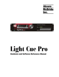
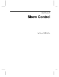
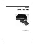
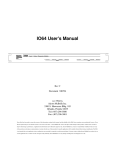
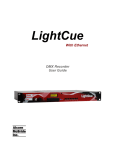
The Input Expander!
User’s Guide
by Alcorn McBride Inc.
Document Revision 1.0
June 2001
Copyright (c) 2001 Alcorn McBride, Inc. All rights reserved.
Every effort has been made to assure the accuracy of the information contained
in this manual, and the reliability of the hardware and software. Errors
sometimes can go undetected, however. If you find one, please bring it to our
attention so that we can correct it for others.
Alcorn McBride Inc. reserves the right to make changes to these products,
without notice, in order to improve their design or performance.
Applications described herein are for illustrative purposes only. Alcorn McBride
Inc. assumes no responsibility or liability for the use of any of these products,
and makes no representation or warranty that the use of these products for
specific applications will be suitable without further testing or modification.
Our Show Control equipment is not intended for use in applications where a
malfunction can reasonably be expected to result in personal injury or damage to
equipment. Customers using or selling Alcorn McBride Inc. products for use in
such applications do so at their own risk, and agree to fully indemnify Alcorn
McBride Inc. for any damages resulting from such improper use or sale.
All warranty and support for the Input Expander and its application is provided
solely by Alcorn McBride.
Product Design: Chris Harden, Jim Carstensen, Jeremy Scheinberg, Steve
Alcorn.
Documentation: Chris Harden
Alcorn McBride Inc.
3300 S. Hiawassee, Suite 105
Orlando, Florida 32835
(407) 296-5800
FAX: (407) 296-5801
http://www.alcorn.com
[email protected]
Contents
Welcome
1
BEFORE YOU START ........................................................................................................1
Technical Support.................................................................................................................1
Installing the Input Expander
3
DIN Rail Mounting...............................................................................................................3
Wall Mounting .....................................................................................................................3
Wiring the Module................................................................................................................4
Powering the Module............................................................................................................5
Connecting To Your Unit......................................................................................................6
Product Specific Functions....................................................................................................7
Welcome
Welcome
Congratulations on choosing The Input Expander for your discrete control
wiring board. The Input Expander makes it easier than ever to directly select the
inputs on the back of many of Alcorn McBride’s playback units. Saving you
hours of wiring time, this little board eliminates needs messy wiring and
provides and easy interface to connect your discrete controls. Good luck, have
fun, and thanks for choosing Alcorn McBride!
BEFORE YOU START
Your playback unit must be set to VOLTAGE MODE
before connecting the Input Expander to it. Your unit will
not understand what you are trying to do and may display aberrant behavior, if it
is in contact closure mode. You could possibly damage the unit by running
contact closure mode while applying voltages to the inputs! Most units
have a DIP switch or slide switch for this setting. Just put it in the correct
position (see your unit’s manual) and that’s all there is to it.
Technical Support
You can obtain information about specifying, installing, configuring, and
programming your Alcorn McBride Input Expander from several sources:
Welcome
For…
Contact…
When?…
Telephone Support
(407) 296-5800
M-F 9am–6pm (EST)
Fax Support
(407) 296-5801
M-F 9am-6pm (EST)
E-Mail Support
[email protected]
Any Time
1
Installing the Input Expander
There are two ways to install the Input Expander. On a DIN Rail, thus the
exciting orange casing or on a wall.
DIN Rail Mounting
Installation
The Input expander has two DIN Rail clips for mounting to a
standard DIN Rail. Shown is a side view of the assembled card.
Just set one clip edge on the top of the DIN Rail and rotate in
the board until you hear the other piece click into place.
Wall Mounting
Upon removing the orange DIN Rail
casing by unsnapping the end caps and
sliding out the circuit board, you’ll find
four screw holes are available for
mounting to a non-conducting surface.
Installing the Input Expander
3
Wiring the Module
Attention! Never wire any module while power is applied.
The module wiring terminals accept one wire per terminal of 17 AWG or
smaller stranded wire. Maximum screw torque is 0.4 Nm.
Example: File Select 1
Simply connect one wire from your contact closure to the screw labeled “1” at
the left of the board, as shown below. Then wire the other side of the contact
closure to one of the screws labeled “VDC” on the bottom.
Example: Loop Strapping a clip
Suppose you want the unit to automatically loop file 6 after bootup. Simply
connect one wire from 6 to VDC and once wire from LOOP to VDC as shown.
Application Note: Making a Test Card
You may want to make a
test card out of your new
Input Expander, and this is
easy to implement with the
wiring diagram to the right.
Just get a couple of LED’s
and a couple of 1KOhm
resistors. Then wire them directly across the screw terminals, if you desire, so
that you now have access to feedback from the unit’s playing and faulted
4
Installing the Input Expander
outputs. This is really handy for testing out multiple units, and since the card
can be used with so many Alcorn McBride Inc products, it’s a cheap investment
for speedy debugging!
Powering the Module
The Input Expander can be powered from the unit’s
power supply or from an external power supply up to
24VDC, depending on how much distance you want to
have between the contact closures and the unit. The
location of the Input Expander in between the switches
and your unit doesn’t matter. There are two jumper
clips at the top right of the board as shown to the right.
Also note the diagram on the circuit board in addition to
the directions below.
Default from the factory, the two jumper clips should be placed on pins 1 & 2 of
JP3 and JP4. This setting is good for a distance of 6ft or less from the unit.
Above 3ft of cable, we recommend shielded wiring. There is a 6ft shielded
cable available for purchase along with this unit. Please see our spec sheet for
the Input Expander for more details. NOTE: The DVM2 family of products
does not have the ability to power the Input Expander. You will need an
external power supply to power the Input Expander when using it with a
DVM2.
Field Power/External Power
To have up to 1000ft between the unit and the switches, you can use an external
power supply to provide the DC voltage you need. The maximum voltage
input on all of our units at this time is 24VDC. We have an AC/DC “wall-wart”
supply available purchase along with this unit, but you are not required to use it.
Please see our spec sheet for the Input Expander for more details.
Make sure your DC
supply is not plugged in.
Simply clip off the
connector from the end
of your DC supply
(typically a barrel jack)
and split the cables long
enough to strip the tips
and connect them as
shown to the appropriate terminals. Plug in your DC supply and use a
voltmeter to verify which wire is the positive DC node and which is ground.
Unplug the DC supply. Connect the ground wire to FIELDGND and the
Installing the Input Expander
5
Installation
Power from the Unit
positive DC wire to FIELDVCD as shown. The two jumper clips should be
placed on pins 2 & 3 of JP3 and JP4 to be in field power mode.
Connecting To Your Unit
Attention! Never connect or remove any cabling while power is applied.
On more time for good measure let us mention this:
Your playback unit must be set VOLTAGE MODE before
connecting the Input Expander to it. Your unit will not understand
what you are trying to do and may display aberrant behavior, if it is in contact
closure mode. You could possibly damage the unit by running contact
closure mode while applying voltages to the inputs! Most units have a DIP
switch or slide switch for this setting. Just put it in the correct position (see your
unit’s manual) and that’s all there is to it.
Verify the unit is not on
and that the external DC
supply is unplugged (if
you are using one). The
cabling necessary to
connect is a 37pin cable
from the Input Expander’s female 37pin DSUB connector to the Discrete
Controls connector (typically female 37pin DSUB also) on the back of your
unit. Tighten the screws of your cabling (if you have any) to the jackscrews on
the connector to secure the cable to the Input Expander. Do this for the unit as
well, and that’s all you need to do! Power up the playback unit and plug in the
DC source (if you are using one).
6
Installing the Input Expander
Product Specific Functions
There are two screw terminals on the Input Expander that connect to inputs on
the various playback units we support with this product. All the other
connections like pause, stop, 1,2,3,4 etc… are universal between our products,
but PRODUCT SPCFIC 1 and PRODUCT SPCFIC 2 connect to inputs that
have meanings that change among units. Also the LightCue has STOP
switched with Pause, so for your convenience here is a listing, by product of
what each of these inputs means to each unit:
STOP
PRODUCTSPCF1
PRODUCTSPCF2
DVM2
STOP
RESUME
STILL
DVMPK8001
STOP
RESUME
PAUSE
MP3 Audio Machine
STOP
MUTE
PAUSE
Digital Audio Machine
STOP
MUTE
PAUSE
LightCue
PAUSE
PLAY
STOP
Installation
Unit
Installing the Input Expander
7