1
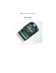
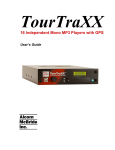
IO64 User's Manual
Rev C
Document 940524
(c) 1994 by
Alcorn McBride Inc.
3300 S. Hiawassee Bldg. 105
Orlando, Florida 32835
Tel: (407) 296-5800
Fax: (407) 296-5801
Every effort has been made to assure the accuracy of the information contained in this manual, and the reliability of the IO64. Errors sometimes can go undetected, however. If you
find one, please bring it to our attention so that we can correct it for others. Alcorn McBride Inc. reserves the right to make changes in these products, without notice, in order to
improve their design or performance. Applications described herein are for illustrative purposes only. Alcorn McBride Inc. assumes no responsibility or liability for the use of any
of these products, and makes no representation or warranty that the use of these products for specific applications will be suitable without further testing or modification. The IO64
is not intended for use in applications where a malfunction can reasonably be expected to result in personal injury. Customers using or selling Alcorn McBride Inc. products for use
in such applications do so at their own risk, and agree to fully indemnify Alcorn McBride Inc. for any damages resulting from such improper use or sale.
IO64 User's Manual
Congratulations on your purchase of Alcorn McBride Inc.'s IO64. The IO64 provides 32
optically isolated inputs, 32 dry relay contacts fused at 0.9 amps, and a user programmable
serial port. It is an ideal I/O expansion device for the V4 and V16 video disc and show
controllers. It can be used stand-alone to execute downloaded scripts containing complex
sequences of I/O changes, and can even control laser disc players or other devices using
its serial port, just like a V4 or V16. It can also be controlled directly from a PC
compatible’s serial port. When used with a PC, a communications library is available at no
charge to build the ninth bit protocol messages used by all Alcorn McBride equipment.
Settings
Addressing
The IO64 is addressed by downloading a Script to it using the SCRIPT.EXE
programming software, much like programming a V16 or V4. For most applications the
unit address may be left at 0.
Memory Configuration
The IO64 has 8K of show script memory, expandable to 24K. The unit is shipped with a
2864 EEPROM, which can be changed to a 28256 if required. No hardware configuration
is required.
DIP Switch
Position
1
2
3
4
5
6
7
8
Alcorn McBride Inc.
Use
not used
not used
not used
not used
not used
not used
not used
on if lcd display installed
IO64 User's Manual
Page 2
Remote Serial Port Operation
The Remote serial port may be configured to operate as an RS-232 port, or to receive
MIDI show control messages. Configure it as follows:
Function
RS-232
MIDI receive
W1
installed
not installed
U11 (a 6N138)
not used
installed
Y2
3.6864MHz
3.0MHz
The MIDI show control messages start IO64 sequences. The protocol is as follows:
Byte
1
2
3
4
5
6
7
8
9
10
Data
f0
7f
xx
02
10
01
xx
xx
xx
f7
Use
system exclusive header
system exclusive extended id
device id = unit number or 7f (wildcard)
show control
control type=sound (10), video (30) or 7f (wildcard)
go command
seq msb in ascii (30-32)
seq mid sb in ascii (30-39)
seq lsb in ascii (30-39) valid seq numbers are 001-256
system exclusive footer
Interconnections
The IO64 has rear connections for serial RS-232 programming (Host), serial device
control (Remote), MIDI (same as Remote, but at a different baud rate and voltage level),
and a power supply connector. The IO64 also has eight Phoenix type connectors for
connecting the inputs, input returns, outputs, and output returns themselves.
The Host (i.e. Programmer) Connector should be plugged into one of the V16's serial
ports when in use. During programming this port should be connected to the PC’s
communications port COM1 or COM2. In both cases a straight through female-to-female
DB-9 cable is used. If the IO64 is not to be connected with a V16, the following table
should be used to wire this connector.
Alcorn McBride Inc.
IO64 User's Manual
Page 3
Host Port
Pin of DB9F
1
2
3
4
5
6
7
8
9
Signal
nc
TXD from IO64
RXD to IO64
nc
GND
nc
nc
nc
nc
The Remote port is wired the same as the connector on a PC compatible, just like the V4
and V16. To connect it to a V16 or V4 port, a DB9 female to female cable with a null
modem twist should be used. To connect to a disc player, our standard CPN-10 or CS-10
cables may be used.
Remote Port
Pin of DB9F
1
2
3
4
5
6
7
8
9
Signal
nc
RXD to IO64
TXD from IO64
nc
GND
nc
nc
nc
nc
There are two banks of Phoenix Input connectors, labeled Inputs 1 - 16, and Inputs 1732. The top bank ( two connectors ) are the input pins, and the bottom bank ( two
connectors ) are the input return pins.
There are two banks of Phoenix Output connectors, labeled Outputs 1 - 16, and Outputs
17-32. The top bank ( two connectors ) are the output pins, and the bottom bank ( two
connectors ) are the output return pins.
Alcorn McBride Inc.
IO64 User's Manual
Page 4
Controlling the IO64
Default Mode
The IO64 is shipped with a script in it that will return input changes to a V16 via a State
Variable Change Message. This means that the V16 is going to use the IO64 simply as an
expansion of it’s own I/O. If IO64 inputs turn on or off, the IO64 will send a State
Variable change message to the V16 to that effect. The IO64 will also accept direct
commands from the V16 to turn on, off, blink, or pulse it’s outputs. If you are going to
use the IO64 in its default mode, you need only plug the IO64 into one of the V16’s serial
ports, and write programming for the V16. If you wish the IO64 to do more than just be
an expansion box for the V16, you can program it to be more intelligent, as described
below.
Using the IO64 Inputs
The IO64 inputs work just like V16 or V4 inputs. Each input can be assigned to provide
start, pause, stop or reset triggers to any or all sequences downloaded to the IO64. The
IO64 can then be programmed to perform stand alone operations in response to these
input changes, or can send a message to the V16 or V4, or both.
The IO64 is shipped with a sample script called IO64MAIN.AMX. This script sends a Set
State Variable message in response to each of the 32 inputs changing. A different value is
sent when the inputs go on, and go off. These state variable values can then be used by a
V16 or V4 to trigger their sequences. This sample script can be used as is, or additional
functions can be added. As shipped, the script sends changes to state variable 32.
The IO64 inputs are shipped with 1.5K ohm thru DIP resistors which are suitable for
operating the inputs off of 24 VDC. Lower operating voltages will require
proportionately lower resistance. The positive voltage should be connected to the top row
of the rear panel connector, with the return on the lower row.
General Serial Control
The IO64 is controlled by serial messages. The IO64 responds to most ScriptOS serial
commands, listed in the V16 manual addendum. The most useful commands are ON,
OFF, BLINK and PULSE, plus START. The first four directly affect the relay outputs of
the IO64. Start is used to start a sequence of events that have previously been
downloaded into the IO64 using SCRIPT.EXE. Note that sequences downloaded to the
IO64 can also be looping and autoexec.
These commands are sent at 9600 baud, 9 data bits, 1 stop bit, and no parity. These
commands can be sent from a user application, from the V16 in a script, or from the script
Alcorn McBride Inc.
IO64 User's Manual
Page 5
software directly to the IO64 without a V16. The commands may be directed to either the
Host (AMAX programming) port or the Remote port (port 1).
Programming or Testing the IO64 Using ScriptOS
The IO64 can operate as a stand-alone controller in many situations. SCRIPT.EXE can
be used to download up to 256 sequences of 64 steps each, which can turn on, off, blink,
or pulse outputs, and receive inputs to trigger sequences. Sequences downloaded to the
IO64 can be looping and autoexec, and so can start themselves and run forever, if desired.
When used with a V16, V4 or PC, these sequences may also be started using the sequence
START command (see the next section for a discussion of V16 communication, and
Appendix A for a discussion of serial protocol in general).
To program the IO64 be sure to select Unit Type IO64 in the SCRIPT.EXE unit
configuration menu.
A particularly easy mode of testing can be achieved by using ScriptOS to talk directly to
the IO64. The IO64 serial port must be connected to a serial port on an IBM PC that is
running the script software via a serial programming cable. The downloaded unit address
must match the address in the Unit Setup section of ScriptOS, both usually being 0. Enter
an output type event or Start event in the script, and hit F10 to single step that line of the
sequence. The script software automatically builds the entire serial message in this
mode. Making a data string in the name strings section of ScriptOS is not
necessary. This script can later be downloaded to the IO64 for stand-alone execution or
triggering by the V16 or V4.
Messages sent from V16 or V4
The IO64 can be controlled by serial messages sent from the V16. The serial
programming port of the IO64 may be connected to any of the serial ports on the V16 or
V4. The V4 or V16 port MUST be configured as an AMAX port in the script program's
serial configuration section. The serial cable used in this configuration is a straight
through DB9F - DB9F cable. This cable can be ordered from Alcorn McBride Inc. The
part number for a one foot long cable is DB9FDB9FP12.
Here is an example of the Serial Port Configuration menu for an IO64 connected to a
V16:
Port
3
Name
io64
Baud
9600
P D S Type
N 8 1 AMAX
Most ScriptOS commands may be directed from a V4 or V16 to the IO64. (Certain
commands would have no meaning if executed remotely; goto, for example.) The
commands are entered into the event editor in a similar format to the local commands,
except that the destination field is filled in with the name of the serial port to which
Alcorn McBride Inc.
IO64 User's Manual
Page 6
the IO64 unit is connected. The serial port may have any name, but must be of type
AMAX, and must match the destination field of the output type commands shown below.
Example
The following is an example line of script that sends a blink command from the V16 to a
IO64 connected to serial port 3, for output number 9 to blink at a 2 second 15 frame rate.
Time
00:00:00
Event
blink
Destination
io64
Data1
02.15
Data2
3
Comment
blink cmd
The following is an example line of script that starts IO64 sequence 1 from the same V16
connection described above.
Time
00:00:00
Event
start
Destination
io64
Data1
Data2
1
Comment
start seq 1
Using the IO64 without a V16
The IO64 can be used or tested without a V16 if so desired.
For operation without a V16, a user-supplied program can be written that outputs the
entire serial message described in the commands above ( including the source address and
checksum ). If this program is to be written on an IBM PC, our library drivers may be
used. These libraries are free, and may be downloaded on our BBS. The BBS can be
reached at (407) 296-5802, 2400, 8N1. In this configuration, the IO64 must also be
connected to the serial port using the cable described above.
Appendix A: Serial Protocol
The ON Command
The ON command turns on an IO64 output.
Six Byte Format: FF aa 02 dd ch
where:
FF = Source address. This byte has the eighth and ninth bits set. The
PC will send a FF, the V16 will send an 80.
aa = Target address. This will be the address of the IO64 as
configured by SCRIPT.EXE
02 = Command byte. This byte tells the IO64 that this is an ON
command.
dd = output to turn on minus 1 (0-31).
ch = Checksum. Sum of preceding five bytes /2 with the ninth bit set.
Alcorn McBride Inc.
IO64 User's Manual
Page 7
The OFF Command
The OFF command turns on an IO64 output.
Six Byte Format: FF aa 03 dd ch
where:
FF = Source address. This byte has the eighth and ninth bits set. The
PC will send a FF, the V16 will send an 80.
aa = Target address. This will be the address of the IO64 as
configured by SCRIPT.EXE
03 = Command byte. This byte tells the IO64 that this is an OFF
command.
dd = output to turn off minus 1 (0-31).
ch = Checksum. Sum of preceding five bytes /2 with the ninth bit set.
The BLINK Command
The BLINK command allows an IO64 output to be blinked at a user-defined rate.
Six Byte Format: FF aa 04 dd pp ch
where:
FF = Source address. This byte has the eighth and ninth bits set. The
PC will send a FF, the V16 will send an 80.
aa = Target address. This will be the address of the IO64 as
configured by SCRIPT.EXE
04 = Command byte. This byte tells the IO64 that this is a BLINK
command.
dd = output to blink minus 1 (0-31).
pp = Period in frames over which to blink. Range is 0-255, allowing
blink rates as slow as 8-1/2 seconds at 30 fps.
ch = Checksum. Sum of preceding five bytes /2 with the ninth bit set.
The PULSE Command
The PULSE command allows an IO64 output to be pulsed on for at a user-defined period.
Six Byte Format: FF aa 05 dd pp ch
where:
FF = Source address. This byte has the eighth and ninth bits set. The
PC will send a FF, the V16 will send an 80.
aa = Target address. This will be the address of the IO64 as
configured by SCRIPT.EXE
05 = Command byte. This byte tells the IO64 that this is a PULSE
command.
dd = output to blink minus 1 (0-31).
pp = Period in frames over which to pulse. Range is 0-255, allowing
pulse durations as long as 8-1/2 seconds at 30 fps.
ch = Checksum. Sum of preceding five bytes /2 with the ninth bit set.
Alcorn McBride Inc.
IO64 User's Manual
Page 8
The START Command
The START command is used to start a sequence from within another sequence. The
V16 can transmit this message to the IO64 to start an entire sequence of previously
downloaded events.
Five Byte Format: FF aa 18 ss ch
where:
FF = Source address. This byte has the eighth and ninth bits set. The
PC will send a FF, the V16 will send an 80.
aa = Target address. This will be the address of the IO64 as
configured by SCRIPT.EXE
18 = Command byte. This byte tells the IO64 that this is a start
command.
ss = sequence number to start minus 1 (0-255).
ch = Checksum. Sum of preceding four bytes MOD 256 with the
eighth bit cleared, and the ninth bit set.
Appendix B: Midi Output from Remote Port
+5
2K Res
-12
Power
GND
Pin 4
TXD
Pin 3
DB-9
MIDI Output from the IO64 may be obtained by connecting a 2K resistor from the power
connector pin 4 (-12v) to the DB-9 remote connector pin 4. This creates a unipolar 24
volt swing between pins 3 and 4 of the DB-9, with the 2K resistor current limiting it to
MIDI levels. These two wires may be connected to a MIDI input opto, and the IO64’s
port set to MIDI on the serial configuration screen.
Alcorn McBride Inc.
IO64 User's Manual
Page 9