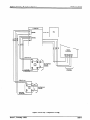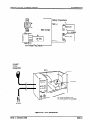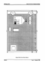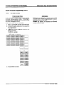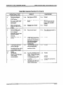
1
Infinite
816
Key Telephone
System
General Description
installation and
Maintenance Manual
For infinite GK-816
Vodavi
Communications
Systems
Infinite
QUICK REFERENCE TABLE OF CONTENTS
816 Key Telephone System
QUICK
REFERENCE
TABLE
OF CONTENTS
SECTION
100
INTRODUCTION
SECTION
200
GENERAL
DESCRIPTION
. . . . . . . . . . . . . .200-l
SECTION
300
FEATURE
DESCRIPTION
. . . . . . . . . . . . . .300-l
SECTION
400
OPERATION
SECTION
500
INSTALLATION
SECTION
600
POWER
SECTION
700
CUSTOMER
SECTION
710
STATION
SECTION
720
CO LINE ATTRIBUTES
SECTION
730
SYSTEM
SECTION
740
EXCEPTION
SECTION
750
INITIALIZE
SECTION
755
PRINTING
SECTION
800
MAINTENANCE
APPENDIX
A
INFINITE
816 PROGRAMMING
APPENDIX
B
INFINITE
816 COMPONENT
Issue 1, January 1992
. . . . . . . . . . . . . . . . . . . . .100-l
. . . . . . . . . . . . . . . . . . . . . . . .400-l
. . . . . . . . . . . . . . . . . . . . . .500-l
UP AND SYSTEM
DATA
BASE PROGRAMMING
ATTRIBUTES
TABLES
DATA
PROGRAMMING
PROGRAMMING
ERS PROGRAMMING
PARAMET
DATA
CHECKOUT
PROGRAIMMING
BASE PARAMETERS
BASE PARAMETERS
AND TROUBLESHOOTING
FORMS
LIST
. . . .600-l
. .700-l
. . .710-l
. . .720-l
. . .730-l
. . . . .740-l
. . . .750-l
. . . . .755-l
.800-l
. . . . . .A-1
. . . . . . . . . .B-1
i
Xtftnite 816 Key Telephone System
TABLE OF CONTENTS
TABLE
SECTION
100
100.1
100.2
100.3
100.4
SECTION
300.1
300.2
300.3
300.4
300.5
300.6
300.7
300.8
300.9
300.10
300.11
300.12
300.13
300.14
300.15
300.16
300.17
300.18
300.19
300.20
300.21
300.22
300.23
300.24
300.25
300.26
300.27
300.28
300.29
300.30
300.3 1
300.32
300.33
300.34
300.35
300.36
300.37
300.38
ii
INTRODUCTION
...............................
loo-1
100-l
100-l
100-l
100-3
PURPOSE ...........................................
................................
SYSTEM COMPONENTS
...........................
REGULATORY
INFORMATION
...................
REGULATORY
INFQRMATION
(Canadian)
200
GENERAL
DESCRIPTION
.....................
.200-1
.......................................
TECHNOLOGY
................................
SYSTEM COMPONENTS
CAPACITY..
.........................................
..............................
SYSTEM SPECIFICATIONS
200.1
200.2
200.3
200.4
SECTION
OF CONTENTS
300
FEATURE
DESCRIPTION
200- 1
200-l
200-4
200-6
.....................
.300-l
.....................................
ACCOUNT CODE
ALARMSIGNALING....................................300ALL CALL VOICE PAGING ...............................
ATTENDANT PGSlTION .................................
...............................
A'ITENDANTOVERFLGW
..................................
ATTENDANT
RECALL
AUTOMATIC
HOLD ....................................
.........................
AUTOMATIC
PAUSE INSERTION
AUTGMATICPRIVACY
.................................
.................................
BACKGROUND
MUSIC
..........................
BATTERY BACK-UP (MEMORY)
...........................
BATTERY BACK-UP (SYSTEM)
BUSY LAMP FIELD ....................................
...................................
CALL ANNOUNCING
CALL FORWARD (PRESET) ..............................
.............................
CALL FORWARD (STATION)
CALL PICK-UP (GROUP) ................................
.....................................
CALLTRANSFER
..............................
CAMP-ON (CALL WAITING)
..............................
CEN’TREX COMPATIBILl-IY
CHAINLNG SPEED BINS ................................
CO LINE ACCESS .....................................
COLINEGROUPXNG
...................................
....................................
CO LINE QUEUING
...............................
CO RING ASSIGNMENT3
COMMON AUDIBLE RINGING (LOUD BELL CONTROL)
.......................................
CONFERENCE
..........................
DATA BASE PRINTGUT (DUMP)
.....................
DIAL PULSE-TO-TONE
SWITCHOVER
..........................
DIAL PULSE/DTMF
SIGNALING
...........................
DIRECT STATION SELECTION
DO NOTDISTURB
(DND) ...............................
......................
DSS/CO AUTGMATIC
LINE SELECT
...............................
EMERGENCY TRANSFER
...............................
END To END SIGNALING
.....................
EXECUTIVE/SECRETARY
TRANSFER
...................................
EXTERNAL PAGING
FLASH
.............................................
........
300- 1
1
300-l
300- 1
300-l
300- 1
300-l
300- 1
300-l
300-l
300-l
300-l
300-4
300-4
300-4
300-4
300-4
300-4
300-4
300-4
300-4
300-4
300-4
300-4
300-5
300-5
300-5
300-5
300-5
300-5
300-5
300-5
300-5
300-5
300-5
300-5
300-6
300-6
Issue 1, January 1992
...........................
FLEXIBLE DSS ASSIGNMENT
.............................
HEADSET COMPATIBILl-IY
...................................
HOLD PROVISIONS
.............
INCOMING INTERCOM SIGNALING SELECTION
................................
INTERNAL ZONE PAGE
LCD-INI’ERACITVE
DISPLAY ............................
.......................
LOUD BELL CONlROL
(CONTACTI
MEGTMEPAGE.......................................300MESSAGE WAITING ...................................
....................................
MUSIC-ON-HOLD
MuTE...............................................300.....................................
NIGHT SERVICE
................................
OFF-HOOK SIGNALING
ON-HOOKDIALING
..................................
ON LINE PROG RAMMING
.............................
PAUSE-R
......................................
.............................
PBX/CENTREX
TRANSFER
.................................
PBX DIALING CODES
PHONE BOX ........................................
............................
PREFERRED LJNE ANSWER
PRIVATELINE
......................................
REALTIME
CLOCK ...................................
SAVE NUMBER REDIAL ................................
..................................
SLA COMPATIBILlTY
.....................................
SPEAKERPHONE
STATION CLASS OF SERVICE (COS) ......................
STATION MESSAGE DETAIL RECORDING (SMDR) ...........
STATION SPEED DIAL .................................
SYSTEM SPEED DIAL .................................
.........................
TOLL RESTRICTION
OVERRIDE
TOLL RESTRIC?ION
FABLE DRXVEN) .....................
TRANSFER RECALL ...................................
UNIVERSALNlGHTANSWER.............................300..................................
VOLUME CONTROLS
WALLTELEPHONE
..................................
300.39
300.40
300.41
300.42
300.43
300.44
300.45
300.46
300.47
300.48
300.49
300.50
300.51
300.52
300.53
300.54
300.55
300.56
300.57
300.58
300.59
300.60
300.6 1
300.62
300.63
300.64
300.65
300.66
300.67
300.68
300.69
300.70
300.71
300.72
300.73
SECTION400
OPERATION
400.1
400.2
400.3
400.4
400.5
400.6
400.7
400.8
400.9
400.10
400.11
400.12
400.13
400.14
400.15
400.16
400.17
Issue 1, January
...................................
INTRODUCnON.......................................400PLACING AN OUTSIDE CALL [AUTOMATIC LINE SELECTION)
ANSWERING AN OUTSIDE CALL .........................
.....................................
SPEAKERPHONE
..................................
VOLUME CONTROLS
MiUTEBUJTON
....................................
BACKGROUND
MUSIC .................................
PLACING OUISIDE
LINE ON HOLD .......................
ANSWERING A RECALL ................................
FLASH ............................................
.............................
PBX/CENIREX
TRANSFER
cALLPIcKup.........................................4ooPLACING AN INTERCOM CALL ..........................
ANSWERING AN INTERCOM CALL ........................
CAMPON............................................400ANSWERINGACAMP
ON ...............................
...............
LEAVING A MESSAGE WAlTING INDICATION
1992
.300-6
.300-6
.300-6
.300-6
.300-6
.300-6
.300-6
6
.300-6
.300-6
6
.300-7
.300-7
..300- 7
..300- 7
..300- 7
.300-7
.300-7
.300-7
-300-7
..300- 7
.300-7
.300-7
.300-7
.300-8
.300-8
.300-8
.300-8
.300-8
.300-8
.300-8
.300-8
8
.300-8
..300- 8
400-1
1
.. .400-l
.400-l
.400.400...400-l
.400.400-l
.400-l
..400.400-
1
1
1
1
1
3
.400-3
.400-3
3
.400-4
.400-4
iii
TABLE
SECTION
QUEUING
PAGING
500
600.1
600.2
600.3
SECTION700
700.1
700.2
400-4
400-4
400-S
...........................................
4-00-S
400-5
400-S
400-6
400-6
400-6
............................................
400-6
MEET ME PAGE ......................................
CALL FORWARDING
...................................
NIGHT’ SERVICE ......................................
SmNG
SY!ZEM TIME AND DATE .......................
4-00-6
400-6
400-6
400-6
ALARM
.............................................
USING ACCOUNT CODES ...............................
PHONE BOX SIGNALING
...............................
UNIVERSAL NIGHT ANSWER
............................
ATTENDANT
OVERRIDE
(CAMP-ON)
......................
LCD DISPLAYS
......................................
400-7
400-7
400-7
400-7
410-l
INSTALLATION
mo-1
400-7
................................
SITEPLANNTNG
......................................
UNPACKING THE KSU .................................
KSU GROUNDING
.....................................
KSU INS’D%LIATlON
...................................
KSU CABLING
.......................................
LIGHTNING
PROTECTION
..............................
KEY TELEPHONE
INSTALLATION
.........................
WALL MOUNT KIT INSTALLATION
........................
PHONE BOX INSTALLATION
............................
EXTERNAL MUSIC SOURCE.
...........................
ALARM INSTALIATION
................................
EXTERNAL PAGING
..................................
LOUD BELL CONTROL
................................
EMERGENCY
‘XRANSFER ..............................
HEADSET INSTALIATION
..............................
BATTERY BACK-UP UNlT (BBU) .........................
RS-232C CONNECTIONS
..............................
SMDR REPLACEMENT
................................
RC.U. REPLACEMENT
................................
SETTING TIME AND DATE DISPLAY ......................
SINGLE LINE SI’ATION ADAPTER (SLA) ...................
600
System
400-4
400-4
SrORING STAnON SPEED NUMBERS
.....................
DIALING A STAnON SPEED NUMBER
....................
SI7XING
SYSTEM SPEED NUMBERS
.....................
DIALING A SYSl-EM SPEED NUMBER
.....................
SAVE NUMBER REDIAL ................................
500.1
500.2
500.3
500.4
500.5
500.6
500.7
500.8
500.9
500.10
500.11
500.12
500.13
500.14
500.15
500.16
500.17
500.18
500.19
500.20
500.21
SECTION
816 Key Telephone
ANSWERING A MESSAGE WAITING INDICATION
.............
CALL’IRANSFER
.....................................
EXECUTIVE/SECRETARY
TRANSFER
.....................
CONFERENCE
COMBINATIONS
..........................
DO NOTDISTURB
....................................
400.18
400.19
400.20
400.2 1
400.22
400.23
400.24
400.25
400.26
400.27
400.28
400.29
400.30
400.3 1
400.32
400.33
400.34
400.35
400.36
400.37
400.38
410.1
iV
b&ite
OF COWTENTS
POWER
UP AND SYSTEM
500-l
500-l
500-l
500-l
500-3
500-3
500-3
500-3
SOO- 10
500-10
SOO- 10
SOO- 10
500-10
SOO- 10
SOO- 13
SOO- 13
500- 14
SOO- 14
500-18
500-18
500-18
CHECKOUT
.......
POWER-UP AND INSTALLATION
CHECKLIST
................
FUNCTIONAL
TEST PROCEDURES
.......................
PRELIMINARY
CHECKLIST
..............................
CUSTOMER
DATA
RASE PROGRAMMING
.600-l
600-l
600- 1
600-l
....
INTRODUCTION
......................................
CUSTOMER DATA WORKSHEETS
........................
.700-l
700-l
700- 1
Issue 1, January
1992
Infinite
816 Key Telephone
DATABASEFTELDS....................................700..............................
PROGRAM MODE ENTRY
INlTLUZATiON
.....................................
RESET FUNCTION &dbvare
Version 3.4 or Higher)
700.3
700.4
700.5
700.6
SECTXON
710
720
730
740
750
750.1
SECTION
SYSTEM
PROGRAMMING
PROGRAMMING
ERS PROGRAMMING
PARAMET
EXCEPTION
INITIALIZE
DEFAULT
755
755.1
SECTION
CO LINE ATTRIBUTES
TABLES
TOLL RESTRlCTION
740.1
SECTION
...........
.....
TABLES
DATA
.....
DATA
.....
DATA BASE PRINTOUT
800
Issue 1, January
1992
MAINTENANCE
................................
AND TROUBLESHOOTING
3
4
5
6
7
730-1
.730- 1
..730- 3
.730-5
.730-6
.730-7
.730-8
.730-8
.730-g
.730-10
.730-l 1
.730-12
.730-13
.730-14
.730- 14
.730-14
.730-14
.730- 14
.730-14
.730-15
.730- 15
.730-15
........
740-1
.740-l
.......
750-l
.750- 1
..........................
BASE PARAMETERS
.720-l
.720-l
.720-2
..720..720..720..720-
............................
RASE P-ERS
DATA BASE CODES
PRINTING
PROGRAIMMING
,710-l
.710-l
.710-2
.710-3
..710- 4
.710-5
.............................
SYSTEM CONFIGURATION
..................................
SYSTEMTIMERS..
..................
EXECUTIVE/SECRETARY
ASSIGNMENTS
................................
LOUD BELL CONTROL
.................................
PBX DIALING CODES
................................
A’lTENDANT
POSITION
PRESET FORWARD RING TIMER .........................
..............................
PRESET CALL FORWARD
................................
CONFERENCETIMER
SMDR ENABLE
.....................................
STATION MESSAGE DETAIL RECORDING (SMDR) ..........
................................
DATE/TIME
FORMAT
STATION SPEED DIAL ................................
........................
PULSE-TO-TONE
SWITCHOVER
FLASH WITH SPEED DL4L .............................
NUMBERING
PLAN ..................................
....................................
NIGHT SERVICE
SYSTEM SPEED DIAL ................................
.....................
SETTING SYSTEM DATEANDTIME
PHONE BOX PROGRAMMING
..........................
.....
SINGLE LINE STATION ADAPTER (SLA) PROGRAMMING
730.1
730.2
730.3
730.4
730.5
730.6
730.7
730.8
730.9
730.10
730.11
730.12
730.13
730.14
730.15
730.16
730.17
730.18
730.19
730.20
730.2 1
SECTION
ATTRIBUTES
1
.700-4
..700- 4
.700-4
....................................
CO LINE GROUPS
.............................
CO LINE CONFIGURYI-ION
COLINERINGING-DAY
..............................
COLINERINGING-NIGHT
............................
FTASHTIMER
......................................
...................................
CORINGDETECT
DIALPULSE..........................................720-
720.1
720.2
720.3
720.4
720.5
720.6
720.7
SECTION
STATION
OF CONTENTS
STATION CLASS OF SERVICE ...........................
.............................
STATION CONFIGURATION
..........................
FLEXIBLE STATION NUMBERS
...................................
COLINEACCESS
...............................
PAGE/PICKUP
GROUPS
710.1
710.2
710.3
710.4
710.5
SECTION
TABLE
System
........
755-1
.755-l
... ,800-l
V
TABLE
Infinite
OF COWTENTS
816 Key Telephone
...............................
GENERAL IN-FORMATION
............................
PREVENISVE h4AINIENANCE
..........................
TESI’ EQUIPMENT
ANJ.3 TOOLS
SPAREPARTS
........................................
..........................
FIELD SERVICE ENGINEERING
...............................
FAULT CLASSIFICATION
...................................
SYSTEM FAILURES
800.1
800.2
800.3
800.4
800.5
800.6
800.7
800.8
800.9
800.10
800.11
A
INFINITE
816 PROG RAMMUNG
APPENDIX
B
INFINITE
816 COMPONENT
vl
800- 1
800-l
800-l
800-l
800-l
800- 1
800-2
800-2
800-2
800-3
800-3
POWERFAILURES
....................................
............................
KEY TELEPHONE
FAILURES
...............................
CO/PBX LINE FAILURES
........................
FEATURE OPERMlON
FAILURES
APPENDIX
FORMS
LIST
System
.......
..A- 1
. . . . . . . . . . . . . . .B-1
Issue
1, January
1992
LIST
SECTION
100
...............................
INTRODUCTION
Figure
SECI’ION
OF FIGURES
lOO- 1 mite
GENERAL
200
Figure 200-l
Figure 200-2
Figure 200-3
816 Key Telephone
DESCRIPTION
mite
mite
Iqfinite
SECTION
300
FEATURE
SECTION
400
OPEWkTION
500
.200-2
.200-3
.200-5
300-1
400-l
Key Telephone
..........
.400-2
................................
mo-1
500-l KSU Mounting
Dimensions
...................
500-2 Key Telephone Wiring .......................
..............
500-3 Wa.lI Mounting
the Key Telephone
...................
500-4 Side View of Key Telephone
......................
500-5 External Connections
500-6 Power Failure Transfer Circuit .................
..........................
500-7 BBU InstalIation
......................
500-8 RS-232C Connections
500-9 SMDR and RCU Module Installation
...........
.......................
500-10 SLA Strap Options.
500-l 1 Typical SIA Layout .......................
500- 12 SLA Mounting
Dimensions
.................
500-13 SLA Cross-Connect
Wiring
.................
POWER
SECTION
700
CUSTOMER
SECTION
710
STATION
SECTION
720
CO LINE ATTRIBUTES
SECTION
730
SYSTEM
SECTION
740
EXCEPTION
740-l
UP AND SYSTEM
DATA
.......
TABLES
ToII Restriction
PROGRAMMING
PROGRAMMING
PROGRAMmG
Flowchart
750
INITIAL=
SECI’ION
755
PRINTING
SECTION
800
MAINTENANCE
APPENDIX
A
INFINITE
816 PROGRAMMING
APPENDIX
B
INFINITE
816 COMPONENT
.609-l
... .700-1
ERS PROGRAMMING
PARAMET
DATA
.500-2
.500-7
.500-8
.500-g
.500-l 1
SOO- 12
.500-15
.500- 16
.500-19
.500-20
.500-22
.500-23
.500-24
BASE PROG-G
ATTRIBUTES
DATA
CHECKOUT
SECTION
1992
200-1
......................
82 6 Executive
600
Issue 1, January
. lOO-2
...................................
SECTION
Figure
............
................
826 Key Service Unit
816 Key Service Unit ................
Station Apparatus
...................
INSTALLATION
Figure
Figure
Figure
Figure
Figure
Figure
Figure
Figure
Figure
Figure
Figure
Figure
Figure
System
......................
DESCRIPTION
Figure 400- 1 Ircfinite
SECTION
loo-1
......
710-1
......
720-1
.....
........
740-1
....................
BASE PARAMETERS
BASE PARAMETERS
.740-3
.......
LIST
750-1
........
AND TROUBLESHOOTING
FORMS
730-1
755-1
... .800-l
.........
...............
A-l
~-1
vii
Infinite 816 Key Telephone
LIST OF TABLE8
LIST
OF TABLES
SECTION
100
INTRODUCTION
SECTION
200
GENERAL
Table
Table
Table
Table
Table
Table
Table
Table
Table
Table
Table
SECTION
300
SECTION
400
500
...............................
DESCRIPTION
FEATURE
Alphabetical
Feature
Index
Table 410.1
Crystal
Liquid
POWER
SECTION
700
CUSTOMER
UP AND SYSTEM
DATA
400-l
...................
410-l
.500-l
Default
710
STATION
ATTRIBUTES
SECTION
720
CO LINK ATTRIBUTES
SECTION
730
SYSTEM
740
EXCEPTION
SECTION
750
INITIALIZE
PROGRAhlMING
SECTION
755
PRINTING
TABLES
SECTION
800
MAINTENANCE
DATA
PROG-G
SLA Program
DATA
.......
.600-l
....
Codes
.700-l
700-2
PROGFMMMING
P ARAMET’ERS
SECTION
500-4
500-5
500-6
500-17
..............................
Values
Applicable
CHECKOUT
BASE PROGRAMMING
SECTION
Table 730-l
(LCD)
300-2
CO Connecting
Block Layout ...................
J-l Connecting
Block Layout ...................
J-2 Connecting
Block Layout ...................
SMDR CaII Record Format ....................
600
Table 700-l
Display
.300-l
...............................
INSTALLATION
500-l
500-2
500-3
500-4
200-7
200-7
200-7
200-8
200-8
200-8
200-9
200-9
200-l 0
200- 11
200- 11
....................
...................................
Table
Table
Table
Table
Table
.20~1
.....................
DESCRIPTION
SECTION
viii
.....................
OPERATION
Table
Table
Table
Table
mo-1
............................
200-l System Capacity
......................
200-2 ElectrIcal Specifications
200-3 EnvironmentaI
Specifications
..................
200-4 Loop Limits.
...............................
........................
200-5 Dialing Specifications
........................
200-6 Regulatory
Number
200-7 Dimensions
and Weight ......................
..................
200-8 Miscellaneous
Specifications
200-9 -Key Telephone Audible Signals ................
............
200- 10 Function Button Visual Indicators
200- 11 CO Line Button Visual Indicators
.............
Table 300-l
SECTION
System
.....
.710-l
......
.720-l
.....
.730-l
................
PROGRAMMING
730- 15
.......
BASE PARAMETERS
BASE PARAMETERS
.740-l
......
.750-l
.......
.755-l
AND TROUBLESHOOTING
... ,800-l
800-l Power Test .................................
...............
800-2 Features w/additional
Equipment
..........................
800-3 Key Station Testing
800-4 Intercom Functions Test ......................
800-5 CO Line Functions Test .......................
800-2
800-3
800-4
800-6
800-8
Issue l,January1992
Infinite
816 Key Telephone
APPENDIX
A
INFINITE
Appendix
Appendix
Appendix
Appends
Appendix
Appendix
APPENDIX
B
1, January
816 PROGRAMMING
1992
FORMS
.........
A-l
A-2
A-3
A4
A-l
Statioi
Pro gramming
........................
DSS Assignments
(Program Code 04) .............
........................
CO Line Pro gramming
System Pro gramming
.......................
...................
A-5 System Speed Dial Numbers
............................
A-6 Exception Tables
..A- 1
.A-1
.A-2
..A- 3
.A-4
...............
B-I
INFINITE
Appendix
Issue
LIST OF TABLES
System
816 COMPONENT
B-l Ir@ni&
816System
LIST
Component
List.
............
.A-5
B-l
lx
IN-FINITE 8 16 ISSUE CONTROL SHEET
INFINITE
ISSUE
1
X
816 ISSUE
Infinite 82 6 Key Telephone System
CONTROL
SHEET
DATE
CHANGE
JANUARY 1992 ?.rst. Release of Infinite 816 General Descriptfon, Installation
dalntenance Manual.
ant
Issue 1, January 1992
Infinite 82 6 Key Telephone
INTRODUCXION
System
SECTION 100
INTRODUCTION
100.1
PURPOSE
B.
Inddence
of Rarm
If the telephone company determines
that
customer
provided
equipment
is faulty
and possibly causing harm or interruption
to the telephone
network,
it should be
disconnected
until repair can be made. If
this is not done, the telephone
company
may temporarily
disconnect
service.
C.
Changes In Service
The local telephone company
may make
changes in its communications
facilities or
procedures.
Ifthese changes should affect
the use of the 8 16 System or compatibility
with the network, the telephone company
must give written
notice to the user to
allow uninterrupted
service.
D.
Maintenance
Limitations
Maintenance
on the 8 16 System is to be
performed only by the manufacturer
or its
authorized agent. The user may not make
any changes and/or repairs except as speIf uncifically noted in this manual.
authorized
alterations
or repairs
are
performed,
any remaining
warranty
may
be voided.
E.
Notice of Compliance
The 8 16 System complies with rules regarding
radiation
and radio frequency
emission by Class A computing
devices. In
accordance with FCC Standard
15 (Subpart J), the following information
must be
supplied to the end user:
This manual provides the information
necessary to program, install, operate, and maintain
the In$ni.te 8 16 Key Telephone System (Figure
100-l).
loo.2
SYSTEM COMPONENrS
The following components
make up the 1r@nff3?
8 16 Key Telephone System:
l
Key Service Unit
l
Key Telephone
. Wall Mount
l
l
loo.3
Program
Kit
Module
Phone Box
REXXJLATORY
INFOFMATION
The Federal
Communications
Commission
(FCC) has established
rules which allow the
direct connection
of the Irsftnite 816 Key Telephone System to the telephone network
Certain
actions
must
be undertaken
or
understood
before the connection
of customer
provided equipment
is completed.
A
Telephone
Company Notifkation
Before connecting
the 1njnfte 8 16 Key
Telephone
System to the telephone
network the local serving telephone company
must be given advance notice of intention
to use customer provided equipment
(CPE)
and provided with the following information:
The telephone numbers
to the system.
to be connected
The FCC Registration
Number located
on the Key Service Unit (KSU): DLP82V7 1202~KF-E
The Ringer Equivalence
Number,
located on the KSU: 0.2A
also
The Universal
System Ordering
Code
(USOC)fack required for direct interconnection with the telephone network
RI21x
Issue
1, January
1992
%
equipment
generates and uses
RF. energy, and if not installed and
used in accordance with the Instnxtion Manual.
it may cause interference to radio communications.
It has
been tested and found to comply with
the limits for a Class A computing
device, pursuant
to Subpart J of Part
15 of the FCC Rules, which are designed to provide reasonable
protection against such interference,
when
operated
in a commercial
environment. Operation of this equipment
in
a residential
area could cause inter100-l
Infinite
INTRODUCTION
POWER
FAILURE
I
816
Key Telephone
System
TRANSFER
I
I
C
lllllllllllllll11111111
llllllllllllllll
ic@%
TELCO
AJPlX
==-II=
z=
==
r=
==
XI-====
z===
z=
---I=
q =
=I
==
I=
z=
5=
I=
q =
=I
MDF (J11
STATION
I
=I
zz
==
i---xx
z=
=z
==
_---
U FUSE
=I
==
==
q =
==
z=
I=
(SLT or DEVICE)
1
MUSIC ON HOLE
Figure
loo-2
-
I 3
100-l
Infinite
816
Key Telephone
BAlTERY
BACKUP
INPUT
System
Issue
1, January
1992
ference, in which case the user, at his
own expense, will be required to take
whatever measures may be required
to correct the interference.”
F.
Hearing Aid Compatibility
The 8 16 Key Telephone
is Hearing Aid
Compatible,
as defined in Section 68.316
of Part 68 FCC Rules.
G. UL Safety Compliance
The hjlntte 8 16 Key System has met safety
requirements
and was found to be fncompliance with the United Laboratories
fUL)
1459 Second Edition standards
for telecommunications
equipment.
The 8 16 is
authorized
to bear the UL mark
loo.4
REGULATORY INFORMATION (Calladil%Il)
Department
of Communications
(DOC!)
Certfffcation
Number:
676-1856-A
Load Number:
19
Ancillary Equipment
Number:
CA21A
Canadian
Standards (CSAI
File Number:
LR57228
A.
Incidence of Harm
If the telephone company determines that
the customer provided equipment
(CPE) is
faulty and possibly causing harm or interruption
to the telephone
network,
It
should be disconnected
until repair can be
effected. If this is not done, the telephone
company
may temporarily
disconnect
service.
B.
INTRODUCTION
816 Key Telephone System
Infinite
Changes In Setice
The local serving telephone company may
make changes in its communications facikties or procedures.
If these changes
should affect the use of the 816 or compatibility
with the network
the serving
telephone company must give written notice to the user to allow uninterrupted
service.
C. Maintenance
Limitations
Maintenance
on the 816 Key Telephone
System is to be performed only the manufacturer or its authorized agent. The user
may not make any changes and/or repairs
except as specifically noted in this manual. If unauthorized
alterations or repairs
are performed,
any remaining
warranty
may be voided.
Issue 1, January 1992
D. Notice of Compliance
The 8 16 Key Telephone
complies
with
rules regarding
radiation
and radio frequency emission by Class A computing
devices. ‘Ihe Ir$nite 816 Key Telephone
system does not exceed the Class A limits
for radio noise emissions as set out in the
radio interference regulations
of the Canadian Department
of Cornmunfcations.
Note: 77~ Canadian Department
of Communications iDOC) label identiifies cert@ed equfpment.
Thfs certfftcation
means
that the
equipment
meets certain tel.ecoOns
network protections, operational
and sqfety reqrdrements.
The Department
does not guarantee the eqtdpment
wtil operate b the user’s
saiisf~tin
Before instaUlrg
this equipment users shf~uld
ensure that it fs prmissible
to be connected to
the fditfes
of the local telecorllJ7un ications
company.
l-he eq~pment
must also be installed using an
In some
acceptable
method of connection
cases, the wrnpany’s
inside wiring associated
with single line iruhidual
sewice may be e-e
tended by means of a certjeed connector assembly (telephone erctension cordl.
The customer
shouLdbeaware~wmpl~ewiththeabove
wnditfon
may not prevent degradation
of serv
ice in some .sihdions.
Repairs to certified equipment should be made
byanauthorized&nadianmaintenuncef~
designated
by the supplier.
Any repairs or alterafims made by the user to this equipmentor
equipment malf~tions,
may giue the telecom~LNuL&~~c~ company cause to request the user
to diswnnect
the equipment
Users should ensurefor thfzirownprotection
that
the el.ecW
ground wnnectims
of the power
lines and internal
uff.lw, iMew mmunf.cations
metallic uxzterpipe system ifpresent
are wnnetted together.
?his precaution
may be partfcularly important 0-1rural areas.
[CAUTIoN]
Users should not attempt
to make
such connections
themselves,
but
should contact the appropriate
electric inspection
authority,
or electrician, as appropriate.
loo-3
Infinite
816
Key Telephone
GENERAC
System
DESCRIPTION
SECTION 200
GENERAL DESCRIPTION
200.1
TECHNOLOGY
The Ir$n&s 8 16 Key Telephone
System is a
microprocessor
controlled,
solid state electronic
switching
system which
distributes
communications
in a non-blocking
format. All
control, switching,
and interface circuitry
is
condensed onto a single printed circuit board
(PCB) located inside the IqjWte 8 16 Key Service
Unit. Refer to Figures 200-l and 200-2.
Switching
is accomplished
through
a solid
state crosspolnt
matrix
that provides
voice
path connections
for eight central ofhce lines,
sixteen Key Telephones,
and eight intercom
paths.
The central processor
unit (CPU) is a 280
microprocessor
that controls the crosspoints
and central office line relays. It also controls
communications
between slave rnicroprocessors located fn each I8 16 Key Telephone
Refer to Figure 200-3.
The 816 Key &vice
Unit (KSUI contains all
system memory which is composed of 16K of
Read Only Memory (ROM) and 4K of Random
Access Memory (RAM). The RAM is subdivided
so that 2K is used as CPU working area and 2K
is used for customer database. The customer
data base memory is protected fi-om loss by a
long life lithium
battery. The system generic
memory (ROM) is contained in a Program Module (PM) that Is interfaced
to the 816 KSU
through
a modular
connecting
arrangement.
This allows easy access for removal of system
software
when upgrading
software
feature
packages.
The system power is regulated by a switching
power supply. This technology
provides high
efficiency with low heat.
A shielded transformer converts the 117V ac into logic voltages
on a separate power supply PCB, mounted
within the KSU cabinet.
Each Key Telephone contains a microprocessor
and circuitry
to monitor
button
activity and
control lamp indications.
A built-in
speaker
permits voice or tone calling to the station
Every telephone has a Busy Lamp Field (BLII
to monitor station activity in the system.
Key Telephones are equipped with ten function
buttons,
eight CO line buttons,
and sixteen
Direct Station Selection (DSS) buttons, which
Issue
1, January
1992
also store Station Speed Dial numbers.
A
three-position
rocker switch is provided
for
easy selectfon of intercom
signaling
modes.
along with separate tone ringing
and voice
volume controls.
For emergency applicattons.
astand-alone
battery backup (BBUI assembly may be connected
to the battery output
terminals
on the 816
KSU. 7h.is retains system power in the event
of commercial
power fallure.
The system protides automatic
cut-through
of
central office (CO) lines to optionally
provided
single line telephones.
These instruments
can
make and receive calls during a commercial
power outage or following a CPU failure.
209.2
SYSTEM COMPONENTS
The following components
make up the In#ni&?
8 16 Key Telephone System:
A
l
Enhanced
Key Service Unit
l
Enhanced
Key Telephone
l
Executive
Key Telephone
l
Wall Mount
l
Program
l
Phone Box
l
Real Time Clock Unit (Replacement)
l
Serial Interface
l
Battery
l
Single Line Adapter
Kit
Module
Unit (Replacement)
Back Up Unit (BBU)
(SLA)
Enhanced
816 Key Service Unit (KSU)
The Enhanced
8 16 KSU (Figures 200- 1
and 200-2) is a sealed, self-contained
unit
that has no user-serviceable
parts inside.
All connections
are accomplished
externally through
Amphenol-type
plugs and
modular connections.
A Program Module
(PM) allows easy expansion
of software
features. A Serial Interface Unit (SIUI and
a Real ‘Bme Clock Unit (RCUI are installed
as standard equipment.
They support Station Message Detail Recording
(SMDR)
and display phone capability.
SMDR allows a customer to track incoming and/or
outgoing, and local and/or long distance
calls by CO line, number
dialed, tfme of
200-l
GENERAt
POWER
FAILURE
TRANSFER
MDF
InfZnite
DESCR.YPTION
816
System
-
CONNECTORS
PROGRAM
MODULE
LOWER
MOUNTING
BFiACKERS
Figure
200-2
Key Telephone
200-l
Iqjinite
816 Key Service
CONNECTOR
Unit
Issue 1, January
1992
Infinite
GENE&IL DEISCRlFl-ION
816 Key Telephone System
/
-
MUSIC
-
BACKGROUND
-
RJ21X CONNECTOR
_ FOR CO LINE
CONNECTIONS
ON HOLD
ADJUST
MUSIC
ADJUST
_ RS 23X CONNECTOR
FOR SMOR PRINTOUT
cFIM:S
SMDR INTERFACE
POWER
Figure 200-2 I..ite
Issue 1. January 1992
MONITOR
LED
816 Key Service Unit
200-3
GENERAL
Infinite
DESCRIPTION
day and date, station that placed the calI,
duration of the call, and account code. The
Real Time Clock Unit provides Executive
telephones
with an LCD time and date
display and a backup system keeps the
time clock functioning
in case of commercial power failure.
B.
I.
Enhanced Model Key Telephone
The Enhanced Key Telephone (Figure 2003) is a fully modular, multi-line
keyset with
voice and tone ringing volume controls.
It
contains eight central of&e line buttons,
ten feature buttons, sixteen Direct Station
Select/Station
Speed Dial buttons, a dial
pad, and an intercom
mode selection
switch. All buttons are of the non-locking
type with easy to see LEDs for quick identification.
C. Executive Model Key Telephone
The Executive Key Telephone (Figure 2003) is identical to the Enhanced
Key Telephone with the addition of a 48 character
interactive LCD display to provide the user
with visual indication
of call status.
D. Wall Mount Kit
The 8 16 Wall Mount Kit provides an attractive, modular means of attaching 8 16
Key Telephones to any vertical surface.
E.. Program Module
The plug-in Program Module (PM) provides
the system instructions
for feature and
operating data.
F.
Phone Box
The Phone Box allows handsf?ee conversations to and from locations that do not
need dialing privileges.
Phone Boxes may
be substituted
for Key Telephones
on a
one-for-one
basis. Refer to Figure 200-3.
G. Real Time Clock Unit (Replacement)
The Real
standard
with LCD,
to protect
cial power
H.
Time Clock Unit is installed &
equipment to provide telephones
with a time and date display and
the time and date from commerfailure.
Serial Interface
Unit
The Serial Interface
standard equipment
to track incoming
and/or long distance
200-4
(Replacement)
Unit is installed
as
to allow the customer
and outgoing,
local
calls (SMDR).
816
Key Telephone
System
Single Line Adapter (SLA)
The Single Line Station Adapter (SLAl is a
device which acts as a command translator and hardware
interface
for two (2)
DTMF sfngle line telephones (2500 type) or
compatible
devices (cordless phones, fax
machines,
modems,
etc...).
This allows
connection
of these devices to the I@nfre
family of ‘flatpack”
key systems. Refer to
Figure 200-3.
There is NO limit to the number
of SLA
adapters that can be installed behind any
one system.
The SIA adapter is not designed to directly
support off-premise
extensions (OPXl applications.
If an OPX is desired on an
Irrj?nf& ‘flatpack”
KSU, additional
customer provided equipment,
with an FCC
registered interface is required.
J.
Battery Back-up Unit (BBU)
This optional Battery Charging Unit 03BUl
and cabling can be directly connected
to
the 8 16 KSU to ma.intafn complete system
operation
in the event of an AC power
fa.ilure. (Batteries must also be provided
separately as they are not included with
the BBIJ). Calls in progress will continue
without
interruption
when commercial
power fails. The BBU will maintain
complete system operation
during a power
outage for up to 24 hours depending
on
system configuration,
and battery size.
200.3
CAPACITY
The 8 16 Key Service Unit (KSU) is housed in a
wall mountable
cabinet that contatns the Key
Service Board (KSB), power supply assembly,
and pre-wired connectors
for eight CO lines,
sixteen Key Telephones,
and eight intercom
channels. One external page port provides twoway external paging capability.
Two Loud BelI
Control ports offer programma ble external signaling. One Music-On-Hold
(MOH) input allows connection
of an external music source
for MOH and Background
Music. Separate Music-On-Hold
and Background
Music volume
adjustments
are provided on the KSU. One
alarm input allows connection
of an external
alarm or other sensing device. Low cost Phone
Boxes may be substituted
for Key Telephones
on a one-for-one
basis. An RS-232C port is
provided for SMDR and data base printouts.
The system contains the necessary interface
circuitry
to enable complete
system battery
backup operation.
In the event of commercial
AC power interruption,
a 24 volt DC battery
Issue 1, January 1992
Infinite
816
Key Telephone
Enhanced
GENERAL
System
Executive
Model
DESCRIPTION
Model
\
\
Phone
Single
Box
Figure
Issue
1, January
1992
200-3
Infinite
Station
Line
Station
Adapter
(SLA)
Apparatus
200-5
GENERAL DESCRIPTION
InjTnite 816 Key Telephone System
assembly provided by the customer w-ill ensure
uninterrupted system operation. A separate
Battery Back-up Unit (BBU) must be provided
for this option.
200.4
SYSTElvI SPECIFICATIONS
System Capacity is listed in Table 200- 1. Electrical, environmental, and Loop Limit specifications are listed in Tables 200-2. 200-3, and
200-4. Dialing Specifications are listed inTable
200-5. Regulatory Formation is listed in Table
200-6. Dimensions and weight are lfsted in
Table 200-7. Miscellaneous Specifications are
listed in Table 200-8. Key telephone Audible
Indications are listed in Table 200-9. Key Telephone Visual Indications are listed in Tables
200-10 and 200-l 1.
200-6
Issue 1, January 1992
Infinite
816
Key
GENERAL DESCRPTION
Telephone System
Table 200-l System Capacity
Ports:
CO/PBX/Centrex
Key Telephone Stations
Single Line Telephones
8max
16max
15max
Attendants:
1 station
Phone Boxes:
Up to 15 phone boxes can be operated on the system.
(Each phone box reduces station capacity by 1)
SMDR Ports:
1 l?S-232C
Page Zones:
Internal:
External:
2 internal page zones
1 external page zone (two-way
(via 8 Single Line Station Adapters)
can be designated
as an Attendant
port located on the right side of the KSU
talk path)
Table 2OQ-2 Electrical Specifications
AC Input to Power Supply
Power Consumption
117V ac k 10%. 60 Hz single phase
90 watts
Power SuppIy
Fuse - AC input
1A. 250V Time Lag
Music
(input)
Input at 2K ohms impedance
source
Source
Contact Rating:
External Page Control
Loud BeIl Control
Alaxm
External
Output
Output
File
from music
l.OA, 24V dc
l.OA, 24V dc
l.OA 24V dc
Page Port:
Impedance
Power
600 ohms @ 0 dBm
5 mW Maximum
Number:
Table 200-S Environmental
Operating Temperature
Recommended
Operating
Storage Temperature
Relative Humidity
Heat Dissipation
WTU’s)
Issue 1, January 1992
Temperature
Speciflcatious
32’ to 104’ F
70° to 78’ F
-40’ to 140’ F
5% to 90% non-condensing
307 BTU’s Ma..um
200-7
InJinite 816 Key Telephone System
GENERAL DESCRIPTION
Table 200-4 Loop Limits
Electronic
(including
Box)
Telephone:
Single Line Telephone
and Phone
500 feet of 26 AWG Cable
1000 feet of 24 AWG Cable
1500 feet of 22 AWG Cable
Table 200-5 Dialing Specifkations
DTMF Dialing
Frequency Deviation
F&e Time
Duration
of DTMF Signal
Interdigit Time
*1.5%
5 msec.
100 msec. minimum
100 msec. minimum
PULSE Dialing
Pulse Dialing Rate
Pulse Break/Make
Duration
60/40 or 66/33
Dialing Memory
System Speed Dialing
Station Speed Dialing
Save Number Redial
40 numbers I1 6 digits)
16 numbers ( 16 digits)
1 number (32 digits)
CO Type
Loop
10 or 20 pps.
start
Table 200-6 Regulatory Number
FCC Registration
Number:
Ringer Equivalence:
USOC Jack
DLP82V-7
0.2A
w2 1x
DOC Certification
Number
DOC Load Number
Ancillary Equipment
Jack
676-1856-A
19
CA21A
UL File Number
CSA File
42U5/ 10946 1
LR57228
200-S
1202-KF-E
Issue 1, January 1992
Infinite
816
Key Telephone
Table
BASIC KEY SERVICE
Height
18.7”
Width
13.4”
Depth
3.0”
Weight
14 lbs.
GENERAL
System
200-7
Dimensions
and Weight
PHONE BOX
Height
UNlT
DESCRIPTION
Width
Depth
Weight
1.75”
5.5”
4”
1 lb.
KEY TELEPHONE
Height
Width
Death
3.5”
8”
9.125”
Table
Memory:
Random Access Memory RAMJ:
Programmable
Head-Only-Memory
Telephone
Music
paths:
(PROM)
Specifications
32K
96K
mic compatible.
8 CO/PBXCentrex
8 talk paths
talk paths
1 channel provides music
and background
music
Channels:
Account Codes:
Number of d&Its per code:
Number of Account Codes:
Speed Dialing Capacity:
System Speed
Station Speed
Issue 1, January
Miscellaneous
Electret
Transmitter:
Talk Paths:
CO/PBX/Centrex
Intercom Paths:
200-8
1992
up to 8 unvetied
unlimited
(non-blocking)
for music-on-hold
digits
296 total bins in system
40 bins per system
16 bins per station
200-9
GENERAL DESCRPTION
Infinite
816 Key Telephone System
Table 200-9 -Key Telephone Audible Signals
‘XYPE OF SIGNAL
Incoming CO Line
Intercom Tone Rir@ng
Intercom Call Announce
(H-P)
Transferred
CO Line
CO Line Fhxill
Message Wait CaII Back
Message Wait Reminder Tone
CO Queue Call Back
Camp-on
Paging Alert Tone
FREQUENCY
DURATION
1215/1471
1215/1471
935
0.8s on/2.4s off; repeated
0.4s on/0.4s off/O.4s on/2.0s
0.2s on/0.2s off (2 bursts)
1215/1471
1215/1471
1215/1471
771
1215/1471
muted 1215/1471
935
0.8s on/2.4s off
0.2s on/.6s off, repeated
0.4s on/0.4s off/O.4s on/2.0s
0.6s on (timed)
0.2s on/0.6s off; repeated
0.2s on/0.2s
off/ (once)
1 sec. (burst)
Intercom Ringback
Busy Tone
Error Tone
Intercom Dial Tone
DND Tone
701
701
701
701
701
Paging Confirmatfon
Programming
Confirmation
Programming
Error
CorArmation
Tone
935
1471
1471
1471
200-10
SIGNAL
off
off
0.4s on/0.4s off/O.4s on/2.0s
off
0.4s on/0.4s off, repeated
0.2s on/0.2s
off, repeated
Continuous
0.2s on/0.2s
off, repeat 3x’s.
pause, 0.5s repeat
1 set burst
1.4 set burst
0.2s on/0.2s
off, 6x’s
1 set burst, 1 time
Issue 1, January 1992
Infinite
GENERAL DESCRIPTION
816 Key Telephone System
Table 200-l 1 CO Line Button Visual Indicators
TYPE OF SIGNAL
Incorning co Ring
Transferred
CO Ring
Recall
Queued Line
Exclusive Hold
System Hold
I-Hold (only when hold preference
In Use
is system)
INDICATOR
30
240
480
30
240
60
30 ipm
FLASH RATES
ipm flash
ipm flash
ipm flutter
ipm flash
ipm flash
ipm flash
double flash
Steadv
Table 200-10 Function Button Visual Indkators
TYPE OF SIGNAL
Call Forward (active)
Message Waiting (active)
Camp-on (active)
CO Line Queue (active)
Do Not Disturb (DND active)
Mute (microphone
off, handset xmit offl
ON/OFF (speakerphone
on/on-hook
dialing
Conference (active)
Speed (momentarily
ON until bin address dialed)
PIntercom Call (Hold Button)
Transfer
Issue 1, January 1992
INDICATGR
FLASH RATES
Steady
15 ipm flash
60 ipm flash
Steady
Steady
Steady
Steady
Steady
Steady
15 ipm flash
Steadv until transfer complete
200-11
Infinite
816
Key Telephone
FEATURE
System
DESCRIPTION
SECTION 300
FEATURE DESCRIPTION
The features of the IrysnLte 8 16 Key Telephone
System are listed and described below in alphabetical
order. An abbreviated feature index
is provided in Table 300- 1.
300.1
ACCOUKT
CODE
An account code is the last field within StaUon
Message Detail Recording
(SMDR), that provides the ability to track specific calls by entering a non-verified,
variable length (up to eight
(8) digits) identffier.
The use of account codes
is optional
and can be entered by the user
during a call. Account codes can be used with
SMDR information
for client bill back purposes.
300.2
ALARM
SIGNALING
The system can recognize either an open or
closed loop from an external relay and transmit
an alarm signal to all avallable (non-busy) Key
Telephone stations with a conttnuous
or single
tone.
The type of alarm tone is selected in
system programming.
300.3
ALL CALL VOICE
PAGING
Any station
may make voice paging
announcements
to all idle stations, Phone Boxes,
and external
paging ports simultaneously.
Paging is a programmable
feature and ls assigned on a per-station
basis.
300.4
ATTENDANT
POSITION
The system allows any Key Telephone station
to be assigned as the system attendant.
The
assigned system attendant
wi.lI receive unattended line recalls and will initiate Night Service.
300.5
ATTENDANT
OVERFLOW
System programming
allows the attendant
sbUon to be programmed
so that if the attendant
is busy or not there, the call will be automatically forwarded to another predetermined
station after a programmed
period of time. fl?efer
to Call Forward-Preset1
300.6
ATTENDANT-
A CO line placed on hold or transferred
will
initiate the recalI timer if the associated timer
has been enabled in programming.
When the
timer expires, the CO line will ring the station
that placed it on hold. If not answered and the
timer cycles again, the attendant
wiIl ring. If
Issue 1, January
1992
still not answered and the timer cycles again,
then alI telephones
programmed
with direct
access of that CO line will ring and flash the
CO line LED at the recalI rate. If still unanswered and the recall timer expires again, the
CO line will be dropped.
300.7
AIJXMATIC
HOLD
Pressing the STA/SPD. CONF, or CAMP/ON
button while on an outside line will automatically place the CO line on hold. This allows
quick internal consultation
and call transfer.
300.8
AUTOhL4TIC
PAUSE XNSERTION
A pause is automatically
inserted into station
and system speed dfal numbers and save redial
numbers
after a programmed
flash in speed
dial numbers
or after recognizing
and diakng
a programmed
PBX dialing code assigned in
the customer data base.
AIJTOX4TIC
PRIVACY
300.9
Privacy is automatically
provided on
municatfon
in the system. If desired,
tem may be programmed
to eliminate
allowing another station to join in on
CO line conversations.
300.10
BACKGROUND
all comthe sysprivacy,
existing
MUSIC
Key Telephones
may receive music over their
integrated
speaker when an optional
music
source is connected to the system. The music
can be turned on or off and the volume adjusted at each individual
station.
Maximum
loudness level can be adjusted on the 8 16 KSU.
300.11
BATTERY BACX-W (MEMORY)
A long life lithium
battery is provided in the
KSU to retain the system data base in the event
of a power outage or the system power being
turned off. Features such as system and station speed dial numbers are also retained during power outages.
300.12
EA’ITERY
BACX-UP
(SYSTEM)
The optional
Irgfinite Battery
Back-up
Unit
(BBU) can br directly connected to the 1r$rrti
8 16 KSU to I rovide full system operation in the
event of a commercial
power outage.
Calls in
progress will continue
without
interruption
when the power fails. The batteries
are recharged via an external battery charger when
300-l
FEATURE
Infinite 816 Key Telephone
DESCRPTXON
Table 30&l
Alphabetical
Feature
Index
LVAILABLI
FEATURE
REQUIRED
Account Code
~~~~~
All Call Voice Pag&rg
Attendant
Posit-Ion
Attendant
Overflow
Attendant
Recall
Automatic
Hold
Automatic
Pause Insertion
Automatic
Privacy
Background
Music
Battery Backup (Memory)
Battery Backup (System)
Busy Lamp Field
Call Announcing
Call Forward (preset)
CalI Forward (Station)
cdl pickup
Call Transfer
Camp-On
Centrex Compatibility
Chaining Speed Bins
CO Line Access
CO Line Grouping
CO Line Queuing
CO Fting Assignments
Common Audible Rtnging
Conference
Data Base Printout (Dump)
Dial Pulse-To-Tone
Switch
Dial Pulse/MMF
Signaling
Direct Station Select
Do Not Disturb
DSS/CO Auto Line Select
Emergency Transfer
End-to-End
Signalling
Executive/Secretary
Transfer
External Paging
Flash
Flexible DSS Assignment
Headset Compatibility
Hold Provision
Incoming Intercom SignalSelect
= Standard
quired
300-2
Feature:
O=Optional:
S
S
S
S
S
S
S
S
S
S
S
0
S
S
S
S
S
S
S
S
S
S
S
S
S
S
S
S
S
S
S
S
S
S
S
S
S
S
S
S
S
S
Requires
addit
Ml’
N
N
N
N
N
N
N
N
N
N
N
BBU
N
N
N
N
N
N
N
N
N
N
N
N
N
N
N
N
N
N
N
N
N
N
N
N
N
N
N
N
N
N
-
System
JZXTERNAL
EQUIPMENT
REQUIRED
N
system
N
N
N
N
N
N
N
Music Source
N
Batteries
N
N
N
N
N
N
N
N
N
N
N
N
N
N
N
N
N
N
N
N
N
SLTS
N
N
Paging Equip
N
N
N
N
N
Alarm
mal hardware
Issue 1, January
re-
1992
Infinite
816 Key Telephone System
FEATURE DESCRIPTION
Table 300-l Alphabetical Feature Index (Cont’a
INTERNAL
AVAILABLE EQUIPMENT
1 REQUIRED
FEATURE
Internal Zone Page
LCD Display
Loud Bell Control
Meet Me Page
Message Waiting
Music On Hold
Mute
Night Service
Off-hook Signaling
On-Hook Dialing
On-Line Programming
Pause Timer
PBX Transfer
PBX Dialing Codes
Phone Box
Preferred Line Answer
Private Line
Real Time Clock
Save Number Redial
SIA Compatibility
Speakerphone
Station Class of Servfce
Station Message Detail Recording
Station Speed Dial
System Speed Dial
Toll Restriction
(override)
Toll Restriction
(table driven)
Transfer Recall
Universal Night Answer
Volume Controls
Wall Telephone
S = Standard
quired
Feature;
O=Optional:
Issue 1, January 1992
S
S
S
S
S
S
S
S
S
S
S
S
S
S
0
S
S
S
S
S
S
S
S
S
S
S
S
S
S
S
0
(SMDR)
Requires
additional
hardware:
N
RCU
N
N
N
N
N
N
N
N
N
N
N
N
N
N
N
N
N
N
N
N
SIU/RCU
N
N
N
N
N
N
N
N
EXTERNAL
EQUIPMENT
REQUIRED
N
Exec Key Telephone
Bell/Ring
Gen.
N
N
Music Source
N
N
N
N
N
N
N
N
Phone Box
N
N
N
N
N
Enh/Exec
Phone
N
Printer
N
N
N
N
N
N
N
Wall Mount Kit
N=No additional
hardware
re-
300-a
FEA-
Injinite 816 Key Telephone
DESCRJFT’ION
the system returns to normal AC operation.
(Batteries must be provided separately.)
300.13
BUSY LAMP FIELD
Each Key Telephone is equipped with an LED
indicator
under each Direct Station Selection
(DSS) button to denote the status of all other
keysets in the system.
300.14
CALL ANNOUNCING
Through a rocker switch on the Key Telephone,
users can select the mode that allows calls to
their phone to be voice announced.
300.15
CALL FORWARD QRESRT)
The system data base n-ray be configured
so
that incoming
CO lines, which
are programmed
to ring a parUcular station, can be
forwarded to another station predetermined
in
programming.
This feature is active if the
station normally receiving the CO ring is busy
or does not answer the call.
300.16
CALL FORWARI)
(STATION)
Each Key Telephone user may direct intercom
calls, transferred
CO line calls, and outside
line ringing to be forwarded to another station
in the system. A forwarded call will signal the
receiving station in the Tone mode, regardless
of the intercom signaling switch mode selection.
300.17
CM& PICK-UF (GROUP)
Tone ringing intercom
calls and transferred
CO lines can be picked up by telephones within
the Same group.
300.18
CXLL TRANSFER
An outside CO Iine can be transferred from one
keyset to another.
By pressing the STA/SPD
button
of the desired party, screened (announced)
transfers
or unscreened
transfers
can be made. The line being transferred
rings
and gives a flash indication
to the receiving
party’s keyset. A line can be transferred
to a
busy party. and a line may be retained
in
transfer if several attempts
are made to find
someone at different keysets.
300.19
CAMP-ON NXU WAITING)
A station
may alert a busy party that an outside line is on hold and waiting for them by use
of the Camp-On feature. To Camp-On
a call;
transfer the call to the desired busy station,
then press the CAMP-ON button.
The called
station will receive an off-hook ring, hold flash
indication
on the waiting line, and a flashing
HOLD button if the Camp-On initiator is still
off-hook. The busy party can press the CAMP300-4
System
ON button, automaticallv
nlacing the first outside line on hold, to confer withtie
Camp-On
inittator.
Or in the event the initiator
has left
the call (no ilashing
HOLD), the party can
press the waiting outside line button,
automatically
placfng their first outside line on
Hold. A station may Camp-On another busy
station without having a CO line connection,
if desired. A CO line camped-on
a station will
recall the Camp-On initiator if not picked up
after the programmable
period of time expires.
Only the attendant
station can Camp-On to a
station in the DND mode with a visual indication only. A Camp-On cannot be made to a
station in conference.
The station designated
ExecuUve in an %ecuUve/Secretary
pair can
be camped-on only by the corresponding
Secretary.
360.20
CENTREX COMPATIJ3lLlTY
The 816 system provides features
that are
Centrex compatible.
such as the ability to
program Flash into Speed dial numbers
and
other general features that help to enhance a
Centrex environment
The 8 16 is compatible
with Centrex Lines ( 1 ML).
300.21
CHAINING SPEED BINS
Speed dfal bins may be chained together by
simply accessing one speed bin, then another
and another as required.
This Is helpful for
accessing Long Distant
carriers or banking
services when Account Codes may be required.
300.22
CO LINE ACCESS
Each telephone can be programmed
to be allowed or denied access to outside lines on an
individual
basis.
Telephones
denied access
can have that line transferred
to them by
another station and the call will appear on its
associated button.
Any statton may be programmed
to ring for any
combination
of lines during the day and different stations can be programmed
to ring on
those lines at night
360.23
CO LINE GROUPING
CO lines can be in one of up to eight groups to
separate line types such as local, FX, PBX etc.
This allows ease of line access assignment
at
the station level in the system data base.
300.24
CO LINE QUEUING
When
placed
line in
When
CO lines are busy, stations
can be
in queue awaiting that CO tie or a CO
the same line group to become available.
a CO line becomes available, the system
signals the waiting station.
If the waiting staIssue 1, January
1992
Infinite
816
Key Telephone
tion is busy when the queued CO line becomes
available, the station is placed at the bottom of
the queue list. Three attempts will be made to
reach a busy station before that station
is
dropped from the queue list. lf a station does
not answer the queue signal in 15 seconds,
that station will be dropped from the queue list.
300.25
CO RING ASSIGNMENT3
CO lines are assigned to ring on a per-station
basis according to system programming.
Any
station may be programmed
to ring for any
line(s) in the Day and/or Night mode.
300.26
COMMON AUDIBLE RINGING
(LOUTI BELLCONTROL)
Incoming
CO line ringing can be directed to
relay controlled contacts.
There are 2 sets of
dry contacts that can be assigned to stations
as Loud Bell Control or to CO lines for CO Line
Control.
An external power source and ringing device or
other ancillary equipment
is required.
300.27
CONFERENCE
l
One internal
Multi-line
Conference.
station can engage in a conference with
two external parties. An external party
can be excluded from the conference by
pressing the CO line button of the party
wishing to remain. The internal station
may place the conference
on Hold by
pressing the HOLD button.
Add-On Conference.
Two internal statfons can engage in a conference with
one external party. There is no limit on
the number of add-on conferences,
except the total number of CO lines connected to the system.
300.28
DATA BASE PRINTGUT (DUMP)
l
Through
a system programming
command,
either portions
of, or a complete data base
dump can be prlnted using the RS-232C connector on the 8 16 KSU.
300.29
DIAL PULSE-TO-TONE
SWITCHOVER
The system will change the signaJng on a CO
Iine from dial pulse to DTMF Vane), allowing
the use of common carriers behind a dial pulse
CO line. ‘IXi.s can be done manually through
dial access or automatically
by storing
the
feature in speed dial numbers.
300.30
DIAL PULSE/D’IlW
SIGNALING
The Irgfinite 8 16 System can be programmed
to
provide pulse or tone sending on a per-line
basis.
Issue
1, January
1992
FEATURE
System
300.31
DIRECT
STATION
DESCRIPTION
SEUXTION
Sixteen buttons are dedicated at each 8 16 Key
Telephone
for immediate
signaling
and connection to other stations.
300.32
DO NOT DISTURB @ND)
Placing a Key Telephone in DND will eliminate
incoming CO line ringing, intercom calls, CO
line transfers. All Call Page announcements,
and Camp-Ons.
The attendant
position
can
override a station in DND using the Camp-On
feature.
‘Ihe designated Secretary in the Executive/Secretary
pair can call an Executive
who is busy or in DND by use of the Camp-On
feature.
Normal outgoing activity may occur
when a station is in the DND mode. By programming,
a station can be denied this feature.
300.33
DSS/CO AUTOMATIC
LINE SEA DSS or CO line can be selected by pressing
the associated button.
automatically
placing
the phone in the dialfng mode.
CO lines will
bring up lual tone and DSS stations are automatically signaled.
300.34
EMERGENCY TRANSFER
In the event of commercial
power failure or
central processor failure, the system can automatically
connect the first three CO lines to
pre-connected
single line telephones.
300.35
END TO END SIGNALING
This feature indicates the capability of the system to accept DTMF tones from stations, send
them through
the public network
and have
them received at the distant end for computer
access, a variety of control functions or inward
call completion at a distant switching
system
300.36
EXECWNE/SECREX’ARY
TRANSFour pan-s of Key Telephones can be desfgnated
to have the ability
of Executive/Secretary
Transfer.
Whenever the ‘Executive”
phone is
in DND or busy, transferred
CO lines and
intercom calls will be directed to the ‘Secretary”
station. The “secretary” of an Exec/Secretary
can ‘camp-on” to an Executive that is busy or
in DND. There are three combfnaffon
types
possible:
l
l
Four pairs
pools.
of ‘Executive-
One Executive
taries.
* One Secretary
tives.
with
Secretary”
one-to-four
for one-to-four
SecreExecu-
300-6
FEATURE
300.37
infinite
DESCRIPTION
EXTERNAL
Page (P). The station user receives a
short
tone burst
and a voice announcement
over the integrated
keyset
speaker, while the microphone
is deactivated, providing privacy.
The called
party must go off-hook to pick up the
call, or switch the selector to Handsfree.
The FIASH button is used to reestablish
dial
tone or transfer a PEX/Centrex
call. Flash can
be programmed
in speed dial for PEX/Centrex
feature operation.
The Flash duration is programmed
on a per CO line basis.
FLZXIBLZ
The key teIephones
are designed to allow the
connection
of a modular
headset.
The user
connects the modular headset to the handset
jack on the telephone leaving the handset in
place. The ON/OFF button is then used to
activate the headset.
300.41
HOLD PROVlSIONS
The following hold conditions
the 8 16 system:
are available
in
- System
&y call can be placed on hold and retrieved by any station with access to that
line.
k
Hold
B.
Hold - Exclusive
Any call can be placed on hold and retrieved only by the initiating
station.
C.
Hold
- Preference
The system can be programmed
either system hold or exclusive
signed as the hold preference.
D.
Hold
Recall
to have
hold as-
Timers
Calls placed on hold are capable of being
timed to recall. The exclusive and system
hold recall timers
are separately
programmed.
300.42
RWOMING INTERCOM
SIGNAL
ING SELECTION
The Key Telephone user can select the method
of receiving intercom calls at that station. The
mode can be easily changed by the individual
user. A rocker switch located on the Key Telephone is used to select the mode. The choices
are:
300-6
Handsfree M. The station user, upon
hearing a short tone burst and a voice
announcement
over the integrated
speaker, can reply Handsfree.
DSS ASSIGNMENF
The order of appearance
of DSS buttons
assigned to telephones can be changed to meet
customer requirements.
300.40
HEADSET COMPATIBILITY
System
Tone Ringer (77. A standard tone ring
notifies the party of an incoming
call.
The party answers by going off-hook.
PAGING
Any station. except one assigned as COS 6, can
make voice paging announcements
to the external paging port
300.38
FLASH
300.39
8 16 Key TeIephone
300.43
INTERNAL
ZONE PAGE
Any station
can make voice paging
announcements
to idle stations in both internal
zones simultaneously
or to either of the two
internal zones.
300.44
LCD-WTERACTNE
DISPLAY
An optional Executive Key Telephone with DISPLAY provides the user with visual indication
of call status. Calls to and from other extensions, number dialed, line used and camp-on
are among the many features displayed.
300.45
LOUD BELL CONTROL (CONTACT)
Incoming
CO line ringing of a station can be
directed to Loud Bell Control contacts.
There
are two sets of dry contacts that may be assigned individually.
An external power source
and ringing device is required.
300.46
?dEET ME PAGE
Any Key Telephone station may answer a Meet
Me Page request on internal or external pages.
This allows a user to answer the page from any
station and be connected to the paging party
via an intercom channel.
300.47
MESSAGE WAITING
Unattended
Key Telephones can be notified of
missed calls. Up to five messages of incoming
intercom calls can be received. Upon return to
the keyset, the user presses the flashing MSG
WAlT button to ring each party leaving a message.
300.48
MUSIC-ON-HOLD
An optional music source can be connected
directly to the system to provide all held calls
with music.
300.49
MUTE
During
handsfree
the Key Telephone
speakerphone
operation,
microphone
can be disabled
Issue 1, January
1992
Infinite
816
Key Telephone
for sftuaffons requfring prtvacy of transmfssfon
or in areas where there are high ambient-noise
levels.
309.50
NIGHT SERVICE
The attendant
places the system in night service by pressing her DND button.*
‘Dais allows
specific phones to &g at night that may or may
not ring during the day. A dial code is provided
for Un.iversal Night Answer; a direct CO line
button appearance or a loop key is required for
this feature.
* The attendant
does not have the DND feature.
300.51
OFF-BOOK SI(;NALING
lf a station has been programmed
to receive
direct outside line ringing and is busy on another call, that station will receive muted ring
to indicate another call Is rfngfng in.
300.52
ON-HOOK DIALING
A speakerphone
equipped Key Telephone
user
can place calls without lifting the handset. and
monitor the call while the called party’s phone
is ringing or on Hold.
300.53
ON LINE PROGRAMMING
Changes to the system data base can be made
without interrupting
normal system operation.
Programming
is done at statlo port 0 1, regardless of intercom number assigned to it.
300.54
PAUSE TIMER
When dialing a speed number,
a timed pause
in digit .sendFng can be inserted into the number.
When the [#I button
is pressed while
entering digits into a speed dial bin, it serves
asacomman
d to the KSU to provide a timed
pause before resuming
digit sending.
The
length of the pause is controlled by the pause
timer. Successive entries of the [#I button will
provide successive timed pauses.
Each programmed
pause utilizes one of the 16 digit
spaces for speed dialing.
When a timed pause is detected during speed
dialing, the LCD will display the letter -P” for
erich pulse. Automatic
pauses that occur as a
result of detectfng a dialed PBX code in last
number red&l or a Pulse-to-Tone
switch-over
in speed dial will not display a ‘P” in the LCD
display.
300.55
PBXKENMEX
TRANSFER
When Centrex or PBX Lines are connected
to
the 8 16 system, users may, by using the Flash
button, transfer callers to other Centrex or PBX
extensions.
Issue
1, January
1992
FEATURE
System
300.56
PBX DIALmG
DESCRIPTION
CODES
The system will allow four two-digit PBX access
codes to be entered into memory.
When one of
these codes is dialed. this signals the 8 16 KSU
that toll restrfction
fs to be applied at the next
dialed digit after the code. If one of the codes
is not dialed, toll restriction
does not apply.
This allows the dialing of PBX extensions
100.
110, 111. etc.
300.57
PHONE BOX
A Phone
Box may be substituted
on a one-toone basis for any Key Telephone
in the 816
System to provide intercom
announcements
and handsfree
talkback
at desired locations.
The user can also orIginate a call to stations
preassigned
in the data base by pressing the
CALL button.
This will signal all stations for
which alarm receive has been enabled.
One of
these stations can respond to this signal by
pressing the DSS button
of the Phone Box
station.
Two-way conversation
is then possible. The box ls assigned a DSS key. and when
called, responds Handsfree to the call. A station can be programmed
as a Phone Box by
assigning COS 6 in station programming.
300.58
PREFERRED
LINE ANSWER
A station
with Preferred Line Answer can answer any assigned ringing CO hne by lifting the
handset.
300.59
PRlVATE LINE
Private Line programming
allows certatn line(s)
to provide flash and ring at a specific station
only. When placed on hold. these line(s) are
active at the indicated
(programmed)
statfon
only,
Night Service will not affect lines programmed as Private Lines. A Private Line can
be transferred
to other stations.
300.60
REAL TXME CLOCK
Provides Executive Key Telephones
and ShdDR
records with an accurate Time and Date. The
system clock recording time and date is protected from commercial
power failure to the
system and continues to function.
This unit is
included with the Enhanced
8 16 Key Service
Unit (KSU) as standard equipment.
300.61
SAVE NUMBER
REDIAL
A number
dialed by a station on a CO line can
be saved permanently
to be used at any time.
300.62
SlA COMPATIBm
A Single Ltne Adapter
(SLA) may be substituted
for a key telephone
on a one-for-one
basis.
This allows connectivity
of industry
standard
300-7
FEATURE
Injinite
DESCRJP’MON
2500 type (MMFJ single line telephone,
and
other devices such as FAX machines,
modems, automatic
attendant,
and Voice Mail
systems.
There is no limit on the number of
816 ports that can be programmed
to SLA
UIlitS.
300.63
S-ONE
Each Key Telephone
contains circuitry
bling two-way
Handsfree
conversations
either internal or external calls.
300.64
enafor
STATXON CLASS OF SERVICE
Icw
Each station is assigned a Class of Service
which governs that station’s dialing privileges.
Six uniquely
defined Classes of Service are
available for assignment
to station on a per
station basis. The system provides a flexible
means of providing Toll or dialing restricUons
through the use of two (2) programmable
Allow
and Deny Tables.
300.65
STATION MESSAGE
CORDING (SMDRI
DETAIL
RE-
STATION
SPEED DIAL
Each station has sixteen user programmable
private speed dial numbers
of up to sixteen
digits in length. These numbers may contain
pauses, Flash comman ds, and ‘No Display”
characters.
The numbers are accessed by going off-hook, pressing the AUTO/SAVE
button. and press the SI’A/SPD button desired.
300.67
SYSTEM
TOLL RESTRICTION
DRI[VEN)
System
(TABLE
The system provides a flexible means of providing toll restriction to individual
stations. By
assigning a ‘class of service” to each station,
long distance calls can be limited at certain
stations through entries into the Allow/Deny
Tables.
300.70
TRANSFER
RECALL
When a CO transfer is completed
to another
station. the Transfer Recall timer is initiated.
If the he is not answered within a specified
amount
of time, the CO line will recall the
initiator within a specified amount of time, the
CO line will recall to the Attendant.
If still
unanswered
by the Attendant
and the recall
timer expires again, the CO line will recall to
all stations in the system. If the CO line still
goes unanswered
and the recall timer expires
again, the CO Iine will be dropped from the
system.
300.71
SMDR allows a customer to track both incoming and outgoing
calls by CO kne, number
dialed. time of day, date, station that placed
the call, and duration of call. The SMDRmodule is included with the Enhanced
816 Key
Service Untt (KSU) as standard equipment.
300.66
300.69
816 Key Telephone
UNIVERSAL
NIGHT
ANSWER
CO lines not marked as a Private Line have
Universal Night Answer fUNA), which provides
key telephones
access to incoming
CO calls
when the system is in night service.
300.72
VOLUME
CONTROLS
Each Key Telephone
user can adjust both
speaker and ring volume independently
by
using the two volume slide switches located on
the right side of the Key Telephone.
360.73
WALL TELEPHONE
Any Key Telephone
can be adapted
mounting
using the Wall Mount Kit.
for wall
SPEED DIAL
A total of forty numbers
can be assigned as
common
system speed dial numbers.
The
numbers can be up to sixteen digits in length,
with pauses taking up digit space. The numbers are accessed by going off-hook, pressing
the AUTO/SAVE
button, and dialing the twodigit access code (10 to 49). The last twenty
speed dial bins will not be monitored
by toll
restriction.
The system speed numbers
are
entered at the attendant
station.
300.68
TOLL, RESTRICTION
OVERRIDE
An outside line can be programmed
to allow
toll restricted stations to dial on that line.
300-8
Issue
1, January
1992
Infinite
OPERATION
816 Key Telephone System
SECTION 400
OPERATION
400.1
INTRODUCTION
The In@tf& 816 Key Telephone
System has a
wide variety of features and flexible programming, allowing each telephone user to program
his/her telephone to meet his/her own individual needs.
This section of the manual contains the operating instructions
for key telephones
and includes an illustration
of the key telephone used
in the 816 system and description
of the keys
on the telephones
and their functions.
It is
designed to provide step-by-step
instructions
for operating the key telephones in the system.
Visual and audible cues which accompany the
various steps in the operation
of the features
are also included.
Literature
similar to these operating
instructions has been prepared for use by the customer in the form of the Inj?n.Qe 816 Station
User’s Guide.
PLACING AN OUTSIDE CAL&
400.2
(MJTOMATIC
LINE s-IONI
a. Press outside line button.
b. ON/OFF button will kght and dial tone will
be heard.
c. Dial desired party.
d. When called party answers, lift handset to
converse or use speakerphone.
ANSWERING AN OUTSIDE CALL
400.3
a. Lift handset.
b. Press slow flashing outside line button.
(If
your telephone
is programmed
with Preferred Line Answer, you may answer an
outside line by lifting the handset.)
SPEAEERPHONE
400.4
a. Press station key of desired party, or press
available
outside
line button
and dial
number.
b. Speakerphone
is activated.
c. Press ON/OFF button to end call.
VOLUME CONTROLS
400.5
There are two
the right side
switch toward
front switch
volume control slide switches on
of the Key Telephone.
Sliding the
you decreases the volume.
The
is for voice, background
music,
Issue 1, January 1992
and speakerphone
volume.
for tone ringing volume.
400.6
MUTEBUXTON
The back switch
is
The MUTE button
provides
privacy
during
speakerphone
or handset
operation
by disabling the microphone.
a Press while off-hook
to activate
(LED
&pS).
b. Press again to deactivate.
BACXGROUND
MUSIC
400.7
a Press [9] on the dial pad (music is heard).
b. Press [9] again and music is discontinued.
(When you pick up the handset or press
the ON/OFF button, music is discontinued automatically.)
400.8
PLACING OUTSIDE LINE ON HOLD
a. If your system is programmed
for Exclusive Hold Preference, press HOLD button
once for Exclusive Hold and twice for System Hold.
b. If your system is programmed
for System
Hold Preference, press HOLD button once
for System Hold and twice for Exclusive
Hold.
ANSWERING ARECALL
400.9
When an outside line has remained on hold for
an extended period of time, you will be reminded with a recalling ring.
a. Press outside line button flashing at very
fast rate.
b. Lift handset to converse.
480.10
FLASH
When connected
to an outside
line, press
FLASH button to disconnect
outside line and
reseize outside line dial tone.
400.11
PBX/CENTRF.XTRANSFER
a We
connected to an outside line (PBX or
Centre.., press FLASH button.
b. Receive PBX/Centrex
transfer dial tone.
c. Dial PBX/Centxx
station number.
d. Hang up to complete transfer.
Note: IThe CO line Flash Timer must be programmed for proper PBX/Centwx
opemtfon
400-l
Infinite 816 Key Telephone System
OPElWl’ION
figure 400-l Iqfinite
816 Executive Key Telephone
Issue 1, January 1992
400-2
Infinite
82 6 Key Telephone
System
OPERATION
Table 400-l
#
CALL PICKUP
When intercom tone ringing, transferred
outside line ringing, or recall ringing is heard at
an unattended
telephone, lift the handset and
dial [6] on the dLal pad to be connected to the
calling party. You must be in the same pick-up
group as the ringing telephone to pick up the
call.
400.13
PLACING AN INTERCOM CALL
a. Press station key of party to be called (if
programmed
at your phone); or diaI station number (0 1 to 15).
b. You will hear ringing If called station is in
T answering
mode; or three bursts of
tone if called station is in ‘H” or ‘F position.
c. Lift handset
or use speakerphone,
tone
bursts stop.
d. Hang up to end call.
400.14
ANSWERING AN INTERCOM
CALX,
With your intercom signal switch in the:
- T mode, you will hear repeated intercom tone ringing & your HOLD button
will slow flash. Lift handset or press
ON/OFF button to answer.
Hang up
or press ON/OFF button to end call.
Issue
1, January
Plan
System Speed Dial preceded by AUTO/SAVE
button
Alarm Reset
External Page
Meet Me Page Answer
call Pickup
Internal All CalI Page
Internal Zone 1 Page
Internal Zone 2 Page
External Zone Page (Can also use 3)
AllCallPage(Canalsouse#)
Music
Attendant
Save Number Redial (preceded by AUTO/SAVE
button)
Allcall
lOTO
2
3
4
6
70
71
72
73
74
9
0
*
400.12
816 Numberixq
1992
-
P mode, you will hear 3 bursts of tone
& a one way announcement.
The
HOLD button
will slow flash.
Lift
handset or press ON/OFF button
to
reply. Hang up to end call.
- H mode, you will hear 3 bursts of tone
and an announcement.
Reply handsfi-ee or lift handset for privacy.
Hand
up or press ON/OFF
button
to end
call.
NOl73: Thestaffonbuitonofthecd.irgpxty
button will-h
If you receke a caUj?om a
phone box you must press that station button
toanswerthecnLL
400.15
CAMPON
If you call a station that is busy and wish to
alert them to your call:
a. Press the CA&P ON button.
b. Called station will receive two bursts of
ringmg.
c. Wait for their response.
If a station is in DND, only the attendant
can
Camp-On.
4Xx-3
InfZnite
OPEIWI’ION
400.16
ANSWERING
A CAMP ON
Lf you are on a connected call, hear two bursts
of muted ringing, and your CAMP ON button
is flashing, you have a call waiting for you.
a. To answer, press the CAMP ON button.
b. Any outside line you are connected to will
be placed on hold. You may converse with
the station placing the call.
400.17
LEAVING AMESSAGE
INDICKl’XON
WAITING
Up to five messages can be left at any Key
Station.
lf you dial a station that is busy,
unattended,
or in DND, you can leave a message waiting indication.
a Press the MSG WAIT button.
b. Called party’s MSG WAlT button will slow
flash.
c. Hang up.
400.18
ANSWERING A BIBSSAGE WAITING INDICATION
lf your MSG WAD? button is flashing at a slow
rate, you have a message waiting for you. The
first message left will be the first one called.
a. Pick up handset.
b. Press flashing MSG WAIT button.
c. Statton that left message will be signaled
with tone ringing.
d. lf called station does not answer, press
MSG WAlT button once to leave message.
400.19
CALLTRANSFeR
Outside
lines can be transferred
from one
phone to another
within the system.
The
transfer can be either screened (announced)
or
unscreened
to either an idle or busy station.
Screened Transfer
While connected to an outside line:
a. Press station button where call is to be
transferred.
b. The called extension signals according to
the intercom signal switch position.
C. When that extension answers, announce
the transfer.
d. Hang up to complete transfer.
Unscreened Transfer
When the called extension begins to signal:
a. Hang up to transfer the call (Recall timer
starts).
400-4
Transfer
82 6 Key Telephone
System
Search
When attempting
to locate a party:
a Press a station key to signal a station.
b. lf the party is not located, press another
station key to continue the search or repeat if necessary.
c. lf the party is not located, press another
station.
d. When the called party answers,
hang up
to complete the transfer.
Answering
A Screened
Transfer
Your intercom will be signaling
according to
the intercom signal switch position.
a. Answer
the intercom
and receive the
transfer nottce.
b. FVess the outside line button flashing on
hold.
400.20
~CUT’XVE/SECRETARY
FER
TlUNS-
lf you are designated the Executive station and
your phone is busy or in DND. all calls will be
routed to the Secretary station.
If you are the designated Secretary station, you
can signal the Executive that is busy or in DND
by using the Camp On feature.
400.21
CONFERENCE
COMBINATIONS
l
Two internal and one external
party internal - Add-On.
or three
One internal and two external - MulULine Conference.
Establishing
a Conference
A maximum
of three parties can be included in
a conference.
The internal party must lift the
handset.
a. Lift handset
b. Select intercom station or dial desired outside party.
C. When called party answers, press CONF
button.
d. Add next conference party by selecting
another outside line or intercom station.
e. When party answers, press CONF button.
f. AU parties are connected.
l
Exiting
a Conference
[controller
only)
There are three methods of exiting a conference:
a. Press the ON/OFF button to ON and repiace handset (to monitor a conference).
Issue
1, January
1992
Infinite
816 Key Telephone
b. Press HOLD button to place outside parties on hold. Hold timer starts.
If one of
the two paxties is internal, that party will
be dropped.
C. Press CONF and hang
up or press the
ON/OFF button to leave the other conference parties still connected in an unsupervised conference.
CONF button will flash
and timer will start. There will be a waming tone before the other parties
are
dropped.
Re-entering
a Conference
When the controller re-enters the conference,
the disconnect timer is reset.
a Lift handset to re-enter a monitored
conference.
b. To re-enter a conference placed on hold,
repeat steps for establishing
a conference.
c. To re-enter an unsupetised
conference,
lift handset (multi-line);
or to re-enter an
unsupervised
conference, lift handset and
press flashing CONF button (add-on). The
CONF button lights steady and confirmation tone will be heard.
Terminating
a Conference:
a. Replace handset or push ON/OFF button
to off. You must be actively in the conference.
400.22
DO NOT DISTURB
Activating
Do Not Disturb
If you have been given the ability to place your
phone in Do Not Disturb:
a, Press the DND button.
b. DND button lights steady.
The DND button
can be pressed while the
phone is ringing to stop the ringing.
Removing Do Not Disturb
1. Press DND button.
2. The button LED extinguishes.
400.23
$UISWG
A station can queue only one line at a time. If
you see that a particular
outside line is busy
and you wish to be placed on a list waiting for
that line to become available:
To place a Queue
a, Press LINE QUE button
b. Press desired busy outside line button.
c. Hang up.
Issue
1, January
1992
OPERATION
System
To Cancel a Queue
a. Lift handset or press ON/OFF button.
b. Press LINE QUE button.
c. Intercom dial tone will be heard.
To Answer
a Queue
If you hear ringing and an outside line of the
line group you queued is slow flashing:
a Lift handset.
b. Press flashing outside line button to answer.
If your station has been programmed
for Preferred Line Answer, you will have the line automatically upon lifting the handset.
400.24
STORING STATION SPEED NUMBERS
Station Speed numbers can be entered by keyset users. System Speed numbers
must be
entered by the first programmed
attendant.
If
no attendant
is spectied, enter at Station 1.
a. Lift handset or press ON/OFF button.
b. Press AUTO/SAVE
button twice.
c. Press SIA/SPD
button where number
is
to be stored. (LED will not light).
d. Select desired outside line or one will be
chosen automatically.
e. Dial telephone number.
f. Press HOLD button.
g. Hang up.
Dialing an [*I initiates a Pulse-ToTone switchover.
- Pressing the (#I during number storage inserts a Pause.
Pressing the FLASH key inserts a
Flash into the speed number.
- Pressing the CONF button inserts a
no-display character causing any
numbers put into the bin after the
CONF button is pressed not to appear on the Key Telephones
display
when the bin is accessed.
NOTE: It is in-pm&d
to ensure unused CO lines
mmmed
inio
a separate line group SO
me prog
the system will not choose an undesired CO line
when airtempting to dial a speed bin rum-her.
400.25
DIALING
BER
A STATION
SPEED NUM-
lf no outside l!ne has been specified in programming,
one will be chosen automatically
or
you can choose one now.
a Press AUTO/SAVE
button.
400-5
Infkite
OPERATION
b. Press sTA/SPD button desired.
c. When called party answers, pick up handset or use speakerphone.
400.26
STORING SYSTEM SPEED NUbSEERS (BSIGNED
ONLY)
A’M’ENDANT
Lift handset or press ON/OFF button.
b. Press AUTO/SAVE
button twice.
C. Dial desired
bin location ( 10 to 49).
d. Select desired outside line or one will be
chosen automatically.
e. Dial telephone number.
f. Press HOLD button.
65. Hang up.
Dialing an [*] initiates a Pulse-ToTone switchover.
Pressing the [#I during number storage inserts a Pause.
Pressing the FLASH key inserts a
Flash into the speed number.
Pressing the CONF button inserts a
no-display
character causing any
numbers put into the bin after the
CONF button is pressed not to appear on the Key Telephones display
when the bin is accessed.
NOTE: It is important to ensure unused CO Iims
are pngr ummedintoasepamtelinegroupso
the system wili not choose an undesired CO line
when attemptfng to dhi a speed bfn r-umber.
a.
400.27
DIALXNG A SYSTEM
SPEED NUM-
BER
If no outside line has been specified in programming.
one will be chosen automatically
or
you can choose one now.
a. Press AUTO/SAVE
button.
b. Dial desired bin location ( 10 to 49).
c. When called party answers, pick up handset or use speakerphone.
400.28
SAVE NUMBER REDIAL
If you wish to save the last number you
dialed:
a Keep handset off-hook.
b. Press AUTO/SAVE
button twice.
To Dial a Saved Number
a. Press AUTO/SAVE
button.
b. Dial asterisk [*I key.
400-6
400.29
PAGING
Stations
off-hook
816
Key Telephone
System
or in DND will not hear the
page.
Lift handset and dial two digit paging code
70 Internal AU Call
71 Internal Zone 1
72 Internal Zone 2
73 External Zone
74 Allcall
b. Speak in normal tone of voice to deliver
message:
a.
Hw
400.30
C.
up.
MEET
ME PAGE
If you wish to have another party call you:
a Pick up handset and dial (741.
b. Request that party meet you on the page.
c. Do not hang up; wait for the requested
party to answer.
Answering a Meet Me Page
a Go to the nearest Key Telephone
and dial
(41.
b. You will be connected
to the party that
paged you.
400.31
CALL FORWARDING
If you have been given the ability to
forward your calls:
Lift handset (intercom dial tone is heard).
a
b. Press CALL JWD button.
C. Press SIA/SPD
button where your ca.lls
are to be forwarded.
d. Hang up.
To Remove Call Forwarding
a Lift handset..
b. Press CALL JWD button.
c. Hang up.
400.32
NIGHT SERVICE
a. Attendant presses DND button at that station.
b. To remove, press DND button agatn.
400.33
SETTING SYSTEM TIME AND
DATE
System Time and Date must be set at the
attendant
station.
a Press AUl?O/SAVE button twice.
b. Dial [501.
c. Enter date and time as follows:
YYMMDDHHMM
Issue
1, January
1992
Infinite
82 6 Key Telephone
OPERATION
System
a Press station button of that phone box.
b. Lift handset or use speakerphone
to converse.
c. Hang up to end call.
400.37
UNIVERSAL+NIGRT
ANSWER
d. W=year80to99
MM =monthOl
to 12
DD = day 01 to 31
HH=hourOOto23
MM = minute 00 to 59
e. Press Hold to enter.
400.34
ALARM
If you hear alarm signals
To reset alarm condition.
a Go off-hook.
b. Dial [21.
400.35
USING ACCOUNT
on your telephone:
CODES
lfyouareonanexistingcalk
a. Press AUTO/SAVE
button.
b. Press pound [#I.
c. Dial account code up to eight digits. Cine
other party will not hear the digits being
dialed.)
400.36
PHONE BOX SIGNALING
If you hear signals on your telephone,
be a signal from a phone box.
Issue
1, January
1992
You hear an outside line ringing at another
station. or common audible ringer, and wish to
answer it:
a Lift handset..
b. Press slow flashing outside line button.
c. You wi.lI be connected to the ringing outside line.
400.38
ATTENDANT
ON)
OVERRIDE
(CAMP-
lf the Attendant
calls a station that is either
busy or in DND and wishes to alert them of a
d:
a Press the Camp-On button. Called station
will receive 2 bursts of ringing.
b. Wait for their response.
it may
400-7
Infinite
8 I 6 Key Telephone
INSTALLATION
System
SECTION 500
INSTALIATION
500.1
500.2
SITE PLANNING
The In$Y&e 816 Key Telephone
System. like
most electronic office equipment,
should not be
subjected to harsh environmental
conditions.
To assure easy servicing and reliable operation, the following factors must be considered
when planning the system installation:
The KSU is designed
only.
l
for wall-mounting
The internal power supply operates on
117V ac. 60 Hz. single phase electricity.
A 3-wire (parallel blade with ground)
receptacle must be provided on a dedicated. separately fused 15 ampere circuit.
l
l
Location(s)
ble runs.
of telephone
conduits
or ca-
The KSU should be within 25 feet of the
telephone
company RI21-X.
The KSU
should be centrally located and assurantes should be made to stay within
prescribed cable lengths.
500 ft. 26 AWG twisted pair
1000 ft. 24 AWG twisted pair
1500 ft. 22 AWG twisted pair
l
A well ventilated
area having a recommended temperature
range of 70 to 78
degrees Fahrenheit,
and a humidity
range of 5 to 90% (non condensing).
LighUng and
servicing.
accessibility
of KSU
for
Protection from flooding, flammable materials. excessive dust and vibration.
Proximity
of radio -tt-w
equipment, arc-welding
devices, copying machines, and other electrical equipment
that are capable of generating
electrical
interferences.
Access to a good earth ground such as
a metallic COLD water pipe. Inspect the
pipe for non-metallic
joints.
Issue
1, January
1992
UNPACgING
THE KSU
a,. Remove the KSU from the shipping carton
and place it on a level working surface,
face up.
b. Inspect the KSU for physical damage. ‘Ihe
KSU has no user-serviceable
parts.
500.3
KSU GROUNDING
To ensure that the system will operate properly, a good earth ground is recommended.
Use
of the Telco ground (source not ‘D” markl or a
metallic COLD water pipe will usually provide
a reliable ground path.
Carefully check that
the pipe does not contain insulated joints that
could isolate the ground. In the absence of the
cold water pipe, a ground rod or other source
may be used. A no. 8 AWG copper wire should
be used between the ground source and the
KSU.
IVOlE The ground wire shDuld be kept as short
aspossibleandcunbecw-tectedtotheground
hglocatedonthebottomofth.eKSUCFigure
200.2).
500.4
KSU INSTALLATION
The KSU is designed for wall mounting
only. It
should not be mounted directly on a masonry
surface.
If the KSU must be mounted
on a
masonry surface, a wooden backboard
of sufficient size should be attached to the wall and
the KSU mounted on the backboard.
1. Mount the KSU on the backboard
using
four fasteners.
me fasteners should be
selected carefully to be capable of supporting the KSU.) Refer to Figure 500-l for
KSU dimensions.
2. Install the ground using an insulated
8
AWG copper wire. Attach one end to the
ground lug on the KSU cabinet and the
other end to a good earth ground.
See
Figure 200-2.
The KSU power supply is located within the
KSU, and all electrical connections
are provided externally.
The power cord exits the KSU
on the bottom.
Also on the bottom is a fuse
holder that contains a 1.0 ampere slow-blow
fuse. Power for the system is distributed
interdY*
The power cord should not be used with a
500-l
Infinite 816 Key Telephone System
INSTALIATION
m-l
A
1Z
18.
3"
Figure 500-l
500-2
KSU Mounting
Dimensions
Issue 1, January 1992
Infinite
3-wire-to-2-wire
plug adapter.
A power line
surge protector should be used to protect the
power supply from electrical surges. The surge
protector
should be installed
in accordance
with the manufacturer’s
instructions
and applicable electrical codes.
Do not plug in the power cord at this
time.
500.5
KSU CABLING
Three (3) Amphenol-type
connectors
are provided on the outside surface of the KSU (Refer
to Figure 200-2).
On the right edge of the front surface is the P- 1
connector which requires a female ended cable
for proper attachment.
Table 500-l lists the
pm function for P-l. On the left side surface
of the 8 16 KSU are two connectors marked J- 1
and J-2.
The J-l connector
is located just
below the J-2 connector.
J-l and J-2 require
90 degree male ended plug cables for proper
attachment.
Tables 500-2 and 500-3 list the
pin functions for J-l and J-2. When connecting cable tails to the KSU, make sure the
designation
on the AMP hood matches
the
designation
at the connector’s
input on the
KSU.
After plugging in the required cables, a ‘horse
shoe” fastener should be placed around the
mated AMP connectors
to secure the cable to
the KSU connector provided.
Verify that the wires are properly cross-connected.
Observe telephone
standard
wiring
color codes where ever necessary.
Cabling should be routed to avoid fluorescent
light fixtures,
electric motors and generators,
welding
equipment.
and radio transmitters.
Additionally,
care should be taken to avoid hot
locations such as steam pipes and furnaces,
and areas where wiring is subject to abrasion.
It is NOT recommended
that power be
applied to the system during the cable
termination
process.
500.6
INSTALLATION
8 I 6 Key Telephone System
L;IGHTNXNGPROTECTION
The I@in& 8 16 Key Telephone System should
have central ofTice lines protected with proper
lightning
surge arrestors.
The central ofhce
lines are exposed to damaging surges induced
by direct or non-direct
lightning strikes.
Issue 1. January 1992
The protection
should contain a complement
of three-element
gas discharge
tubes which
ground high potential surges, and associated
circuits to absorb and fflter lower-level
surge
potentials.
Care should be taken to ensure
that not more than one set of protectors
be
installed on central office lines at installation
premises. Improper installation of line protection can present a serious safety hazard.
500.7
KEY TELZPHONE INSTALf&TION
A maximum
of 16 Key Telephones
may be
installed with the 816 Key Telephone
System.
Each Key Telephone requires 2 pair (4 wires)
for proper wirfng.
It is recommended
that 3
pair twisted pair cable be used to connect the
telephones
to the system on a ‘home run”
basis. The telephone end of the cable should
be terminated
on a modular jack as shown in
Figure 500-2.
At the MDF end of the home
run, the cable should be terminated
on a separate station connecting
block (66Ml-501
for
cross connection to the *J” cables. This method
of cabling will allow for easy isolation of station
equipment
during
troubleshooting
procedures.
WALL MOUNT KIT INSTALLATION
500.8
All connections to the Key Telephones
are fully
modular.
To wall mount the Key Telephone,
it
is necessary to have one Wall Mount Kit and
one 630-A type modular wall mount jack assembly equipped with two mounting
lugs (See
Figure 500-3).
a. Remove the mounting
cord from the Key
Telephone.
This cord will no longer be
needed, but should be retained for mafntenance purposes.
b. Substitute the short modular
cord on the
wall mount baseplate
for the removed
mounting
cord.
the plastic number
retainer
upC. Rotate
wards to expose the screw underneath.
Remove the screw, and slide the cover
plate under the number retainer towards
the hook-switch.
d. Replace the cover plate with the handset
retainer tab that is mounted
in the wall
mount
baseplate
and secure with the
screw from Step c. above.
e. Rotate the plastic number retainer downward and snap into place.
f. Align the mounting
tab on the outer edges
of the wall mount base with the holes on
the Key Telephone base. Snap shut and
fasten with the screw.
500-3
Infinite 816 Key Telephone
INSTALLATION
Table 600-l
I
COhe#
1
2
3
4
5
6
I
7
8
500-4
I
Function
Tl
l-2
R2
l-3
R3
T4
R4
75
Fe3
T6
R6
T7
R7
223
CO Connecting
I
Block
System
Layout
MDF Cable
WH/BL
WH/OR
OR/WH
WH/GN
GN/WH
WH/BN
BNfWH
wH/SL
SL/wH
RD/BL
BL/RD
RD/OR
OR/RD
RD/GN
I
Connector
26
Pin
I
27
2
28
3
29
4
30
5
31
6
32
7
33
Issue 1, January
I
1992
Infinite
816 Key Telephone
Table
Station
#
Statfon
1
Station
2
Station
3
Station
4
Station
5
Station
6
Station
7
Station
8
500-2
YELLOW
WH/OR
OR/WH
GREEN
RED
BLACK
YELLOW
GREEN
RED
BLACK
YELLOW
GREEN
RED
BLACK
YELLOW
GREEN
RED
BLACK
YELLOW
GREEN
RED
BLACK
YELLOW
GREEN
RED
BLACK
YELLOW
WH/BL
BL/WH
WI-l/OR
OR/WH
WH/BL
BL/WH
WH/OR
OR/WI-I
WH/BL
BL/WH
WH/OR
OR/WH
WH/BL
BL/WH
WH/OR
OR/WH
WH/BL
BL/WH
WI-I/OR
OR/?VH
WH/BL
BL/WH
WH/OR
OR/WH
EXTERNAL
PAGE (VOICE)
EXTERNAL
PAGEDRY
CONTACTS
ALARM
LOUD BELL CONTROL
1
LOUD BELL CONTROL
2
SPARE
SPARE
SPARE
1, January
J-l
1992
Connecting
2 pr. Twisted
Station Cable
WH/BL
BL/WH
WH/OR
OR/WH
WH/BL
BL/WH
Telephone
Line Cord
GREEN
RED
BLACK
YELLOW
GREEN
RED
BLACK
MUSIC-ON-HOLD
Issue
INSTALLATION
System
Block
Function
VT1
VRl
DTl
DR 1
vr2
vR2
M-2
DR2
VT3
vR3
m-3
DF?3
v-l-4
vR4
DT4
DR4
VT5
v-R5
D-r5
DR5
VI’6
VFZ6
D-l-6
DR6
vr7
vR7
DT7
DR7
VI-8
vR8
M-8
DR8
MOH
MOH
EPVT
EPVR
EPCTL
EP’XL
ALMT
ALMR
LBClT
LBClR
LBC2T
LBC2R
Layout
MDF
Cable
JVH/BL
BL/WH
WH/OR
OR/WH
WH/GN
GN/WH
WH/BN
BNfWH
wH/SL
SL/wH
RD/BL
BL/RD
RD/OR
OR/RD
RD/GN
GN/RD
RD/BN
BN/RD
RD/SL
SL/F?D
BK/BL
BL/BK
BK/OR
OR/BK
BK/GN
GN/BK
BK/BN
BN/BK
BK/SL
SL/BK
YL/BL
BL/YL
YL/OR
OR/n,
YL/GN
GN/YL
YL/BN
BN/YL
YL/SL
SL/YL
VI/BL
BLM
VI/OR
ORM
VI/GN
GNM
VI/BN
BNM
vI/SL
SL/Vl
PIN #
26
1
27
2
28
3
29
4
30
5
31
6
32
7
33
8
34
9
35
10
36
11
37
12
38
13
39
14
40
15
41
16
42
17
43
18
44
19
45
20
46
21
47
22
48
23
49
24
50
25
500-5
InfZnite
INSTALLATION
Table 500-3
Station #
Station 9
Station
10
Station
11
Station
12
Statlon
13
Station
14
Station
15
Station
16
500-6
Telephone
Line Cord
GREEN
RED
BLACK
YELLOW
GREEN
RED
BLACK
YELLOW
GREEN
RED
BLACK
YELLOW
GREEN
RED
BLACK
YELLOW
GREEN
RED
BLACK
YELLOW
GREEN
RED
BLACK
YELLOW
GREEN
RED
BLACK
YELLOW
GREEN
RED
BLACK
YELLOW
J-2 Connecting
2 pr. ‘IWsted
Station Cable
WH/BL
BL/WH
WI-I/OR
ORfWH
WH/BL
BL/WH
WI-I/OR
OR/-WI-l
WH/BL
BL/WH
WH/OR
OR/VA-I
WH/BL
BL/WH
WH/OR
OR/WH
WH/BL
BL/WH
WH/OR
OR/WH
WH/BL
BL/WH
WI-I/OR
OR/-WI-l
WH/BL
BL/WH
WI-I/OR
OR/WI-I
WH/BL
BL/WH
WH/OR
OR/WH
Block
Function
VT9
DR9
VT 10
VR 10
DT 10
DR 10
VT 11
VR 11
DT 11
DRl 1
VT 12
vR12
M-12
DR 12
vr 13
vR13
D-r 13
DR 13
VT 14
vR14
m 14
DR 14
vr 15
VR 15
DT15
DR15
IT 16
VR16
DT16
DR16
816 Key Telephone
System
Layout
MDF
Cable
WH/BL
BL/WH
WI-I/OR
OR/WI-I
WH/GN
GN/WH
WH/BN
BN/-WH
wH/SL
SL/wH
RD/BL
BL/RD
RD/OR
OR/RD
RD/GN
GN/RD
RD/BN
BN/RD
RD/SL
SL/RD
BK/BL
BL/BK
BK/OR
OR/BK
BK/GN
GN/BK
BK/BN
BN/BK
BK/SL
SL/BK
YL/BL
BL/YL
Connector
26
1
27
2
28
3
29
4
30
5
31
6
32
7
33
8
34
9
35
10
36
11
37
12
38
13
39
14
40
15
41
16
Issue 1, January
1992
Infinite
82 6 Key Telephone
System
INSTALLATION
KSU
23 PAIR
CABLE
t+--
r
I
GREEN
RED
mIffi
(llP)
P4V
-24v
I
\
/
PHONE
BOX
CONNECTIONS
GREEN
(TIP)
.24V
Figure
Issue
1, January
1992
500-2
Key Telephone
Wiring
500-7
Q,
c
Infinite 82 6 Key Telephone System
INSTALLATION
WALL MOUNT
JACK
0
\r-l / 1 7iI
\
I3
.
&
I
[I
l
I
y&~LMEyuur\
HANDSET
RETAINER
.
\
\
~
0 TELEPHONE
WALL MOUNT
TELEPHONE
w
500-8
. .
’ ,
WALL JACK
500-3 Wall Mounting the Key Telephone
Issue 1, January 1992
Infinite
816 Key Telephone
INSTALLATION
System
HINGE TABS
UPPER HOUSING
+
LOWER HOUSING
(BASE PLATE)
KNOBS ADJUSTED TO MINIMUM
VOLUME POSlTlONS
Figure
Issue 1. January
1992
500-4
Side View
of Key Telephone
500-g
INSTALLATION
g. The telephone can now be mounted to the
wall by matching the two keyhole slots on
the baseplate with the lugs on the modular cover assembly.
Check to make sure
that the modular connector on the baseplate has a firm connection
with the wall
jack500.9
PHONE BOX INS’I’ALL&TION
The Irt$n& 816 Phone Box can make calls to
preassigned
statfons as well as receive intercom calls.
The unit should be located in
weather protected areas where paging or monftorlng is required.
The Phone Box consists of a top housing and
bottom mounting
plate. The top housing has
a speaker, mlcrophone,
wire term&&s
and
electronic
ctrcuitxy.
The housings are separated by inserting a thin, flat-edged tool at the
bottom rim of the assembly.
By pressing inward on the recessed retaining tab, the assembly wilI open.
The connection
of the Phone Box(es) to the
KSU is identical to that of the Key Telephone.
Refer to the Key Telephone Installation
paragraph.
The bottom plate of the Phone Box assembly
is fastened to the wall by mounting
with no. 8
or larger pan-head screws. The cable is routed
through the cable-entry holes provided on the
bottom plate and is connected
to the screw
terminal
strip on the upper housing.
Four
screw tenntnals
are identified by wire color on
the silk-screened
printed circuit board to correspond
with the wiring
sequence
at the
punchdown
connector at the Main Distribution Frame (MDF).
The slack wiring
should
be pulled
back
through
the bottom mounting
plate and the
top housing snapped shut.
Refer to Section
7 10.1, Station Class of Service to program
Phone Boxes.
500.10
EXTERNAL BKTSIC SOURCE
Music-On-Hold,
as well as Background Music,.
can be connected using a customer provided
music
source.
Separate
Music-On-Hold
(MOH) and Background
Music (BGM) volume
adjustments
are provided on the KSU.
Background
Music levels are also adjustable
at each Key Telephone set. Connections
are
made on the J-l connector,
the MOH pair.
Refer to Table 500-2.
500.11
ALARMINSTALLATION
An alarm signal can be transmitted
to each
station (except Phone Boxes) in the system.
500-10
Infinite 8 I6 Key Telephone System
When activated by an external alarm system,
a continuous
tone is transmitted
to the station
speakers.
Leads from the external alarm are
connected
to the J-l terminals,
ALMT and
ALMR. Refer to Table 500-2. Also refer to Section 7 10.1 for programming
alarm states. After the alaxm has sounded, the system must
be reset by first clearing the alarm condition
on the external system and then at any station
by dfallng 121.
500.12
EXTERNAL PAGING
An amplifier for external paging may be connected to the In#rtf& 8 16 Key Telephone
System. Any telephone in the system can access
this paging equipment
by using a dial code.
There is one External Paging Zone (without
amplifier) provided in the 8 16 System. Paging
can be two-way.
The output impedance
of the paging zone is
600 Ohms at 0 clBm. The low-level voice signal
output is specified at 5 mil.Iiwatts.
Dry contact
control is provided to switch on the external
amplifier equipment
or to momentarily
remove
Background
Music, if externally
supplied
to
the paging device.
All connections
are made on the J-l punchdown connector.
Refer to Table 500-2. The
voice output from the Key Telephone
System
is provided on the EPVT and EPVR pair. The
make” contacts are identified as pair EPCTL.
500.13
LOUD BELL CONTROL
The IQ‘%& 8 16 System provides relay contact
closure for activation
of external
signaling
equipment
during incoming
CO line ringing.
The Loud Bell Control is selected by programming in the customer database.
Either or both of the Loud Bell Control circuits
may be assigned to a station. The Loud Bell
Control dxy contacts will follow the ringing
condition
of that station. Locate the LBClT
and LBC 1R terminals on the connecting block.
Two wires are connected
to these tenninalS
and routed to customer
provided
signaling
equipment
(Refer to Figure 500-5).
All incoming CO lines assigned to ring for the
programmed
Loud Bell Control station will
activate the Loud Bell Control,
causing the
LBC contacts to sequence in a 1 second ON/3
seconds OFF rate until all lines have been
answered by Key Telephone
users. The LBC
contacts are current-rated
at 1 ampere/24V
dc.
500.14
EMERGENCY TRANSFER
In the event of a commercial
AC power
inter-
Issue 1. January 1992
Winite
816 Key Telephone System
INSTALLATION
Jl CONNECTOR
MUSIC
PIN #
42
YUOR
SOURCE
7
MOH
INPUT
43
18
YUGN
GNJYL
EPVT
OUTPUT
TO SPEAKERS
VOICE
INPUT IMPEDANCE
-600 otms@odm
EPVR
----------------------,
EPCTL
MAKE CONTROL
Contact
Rating 24 VDC
EPCTL
LBC
1T
RINGER
LOUD BELL
CONTROL
1
contact
Rating
24 VDC
-
I$
CONTACT
RATlNG
1A 24VDC
CUSTOMER
VOLTAGE
PROVIDED
SOURCE
DC
CUSTOMER
VOLTAGE
PROVIDED
SOURCE
DC
Y
FIgure500-5ExtemalConnections
Issue 1. January 1992
5ocbll
INSTALLATION
816 Key Telephone System
Infinite
I
PROCESSOR
OR
POWER FAILURE
TRANSFER STATION
f STATION WIRING
;,
f 6-CONDUCTOR
; MODULAR JACK
I
KSU
I
FROM RJ21 X
I
I
-
NOTE1
I
I
i
RED
PFr3
i
I
i
i
I
i
I-
PFT2
I
I
!
1
I
I
I
I
-
-
NOTE 1: Contacts
are shown in power failure
np
i
mode.
Ngure 500-6 Power Failure Transfer Circuit
500-12
Issue 1, January 1992
Infinite
816 Eey Telephone System
INSTALLATION
ruption, the first three CO/PBX lines will automatically transfer to single line telephones
(if
installed) for emergency communicatfons
(Refer to Figure 500-6).
These single line telephones should be equipped with ringers. They
can be MMF-type
instruments
or rotary dial.
Connection
is made on the Power Failure
Transfer jack located on the side of the KSU.
500.15
BEAD!3ET INSTALLATION
The Key Telephone is designed to operate with
industry
standard modular
headset adapters
and operator headsets.
To modify a Key Telephone to support an external headset, plug the
headset adapter cord Into the hands&jack
on
the Key Telephone
base. Plug the telephone
handset
cord into the headset adapter box
where indicated by the headset manufacturer’s
instnlctions.
Then turn to the Programming
section of this
manual, staffon configuration
(Program Code
02). When the headset option has been enabled for a particular
station, speakerphone
operation
is automatically
disabled and such
features as On-Hook Dialing and Handsfree
speakerphone
are rendered inoperable.
However, incorning
page/voice
announcements,
tone ringing and background
music will still be
heard over the keyset speaker.
500.16
BATTERY BACK-UP UNIT (BBU)
The Battery Backup Unit IBBU) houses two 12
Volt batteries connected in series which provide 24 Volts of DC power. The BBU contains
an AC input cord whfch provides
charging
power when the batteries are not in use. Batteries are not included.
A 10 inch 14 gauge jumper wire is provided for
interconnection
of the two batteries.
Four
adapter wires (approximately
2 inch) are provided for matching the exact battery terminal
size. The BBU will interface batteries with 187
or 250 size male faston-type
tab connectors.
A
plastic tiewrap is provided for securing
the
batteries once installed.
Any UL recognfzed battery may be used with
the BBU. gel type batteries are recommended.
The larger ampere hour the battery, the longer
it will take to recharge.
k
All Electronic
Key Systems will begin to
operate intermittently
below a certain input voltage.
Typically reliable operation
will be maintained
to 90 percent of full
voltage.
Capacity
The following
table shows appmte
Battery Backup times for a fully charged
battery to discharge to 90 percent voltage
under different load conditions:
B.
Dimensions and Weight
- 8 lnhfgh, 13.5 hwide,
-
Weight
C. Specifications
-
Output
Current
voltage
Gel-type
Charger
Cut off
1992
fused at 4A, 250 V
limited, constant
charger
batteries
float voltage is 27.6 V
voltage pofnt is 21 V
D. Power Requirements
-
Input:
117V ac, 60 Hz
Fused at 0.5 A. 250 V
E. Environment
-
F.
Temperature:
70 to 78 F
Humidity:
5 to 90%
Recharge Time
-
Time Required to Recharge batteries
that have been discharged completely:
7AH Batteries = 24 hours
l&I-I Batteries = 48 hours
G.
hstallation
- Introducff on
Refer to Figure 500-7 for
input socket. The input
system must be a female
connector.
Installatton
Checklist
- The following
items
install the BBU:
1. One BBU with wire kit
wrap.
2. Four no. 12 pan-head
mounted).
the locaff on of the
socket of the key
Mate-N-Lok
lype
are required
to
(5 wires)
and tie-
screws
(if wall
3. Screwdriver.
4. Backboard
Issue 1. January
without
7.75 indeep
batteries:
11 lb.
or wall shelf, if appltcable.
500-13
Injinite
INSTALLATION
H.
MOUIlthlg
1.
2.
3.
4.
5.
6.
The BBU must be located within 6 feet of
an AC receptacle and 2 feet of the KSU.
Check clearances
to ensure that both
cords will extend to their proper locations.
The BBU is designed to be mounted
on a
backboard.
(either a backboard of its own
or mounted on the KSU backboard).
Mark for screw placement, either by measuring [the 2 top keyhole mounting
slots are
8 3/4” on center) or by placfng the BBU
against the backboard
(before installing
batteries) and marking the location of the
two top slots.
Partially insert two no. 12 pan-head sheet
metal screws into the backboard.
Suspend the BBU on these two screws.
The large section of the keyhole will allow
the unit to easily pass over the screwhead.
Slowly lower the BBU so the small section
of the keyhole is directly behind the screw
head.
Tighten each screw so the unit fits snugly
against the backboard.
Insert two more screws into the bottom of
the BBU where two more keyhole mountfng slots are located.
I.
Grounding
To ensure that the BBU will operate properly, a good earth ground is recommended.
A metallic COLD water pipe will usually
provide a reliable ground path. Carefully
check that the pipe does not contain insulated joints that could isolate the ground.
In the absence of the cold water pipe, a
ground rod or other source may be used.
A No. 8 AWG copper wire should be used
between the ground source and the BBU.
A ground lug is provlded on the lower-left
side of the BBU.
The ground wire should be kept as short
as possible and should be connected to the
ground lug located on the bottom of the
816 KSU.
J.
Battery
Installation
and Connections
Before connecting
the batteries,
ensure the BBU is unplugged
from the
AC outlet and the ON/OFF switch on
the BBU is turned off.
500-14
816 Key Telephone
System
1. Remove the BBU cover by turning
the 4
screw locks and lifting the cover.
2. Install the two 12V dc batteries in the
battery compartment
Thread the plastic
tiewrap through the vent holes in the side
of the battery compartment
and fasten
around both batteries.
Cinch the tiewrap
ugl-lt.
3. Connect one of the adapter wires to the
black 10 in. jumper wire. Now m&all this
jumper wire assembly between the NEG i-1
terminal of battery 1 and the POS (+I terminal of battery 2.
4. Connect another adapter wire to the BBU
red battery wire. Now connect this wire to
the POS (+I terminal of battery 1.
5. Connect the BBU black battery wire to the
NEG (-) terminal of battery 2.
6. Make sure the Key System being connected is plugged into the ac outlet and
turned on. Then
connect the BBU dc
output cable to the battery input of the
KSU.
Make
sure the BBU power switch is in the
7.
OFF position.
Then plug in the ac power
cord.
8. Turn the power switch on the BBU to ON.
500.17 RS232C CONNECTIONS
Figure 500-8 fflustrates the standard pm configuration
used with the In$n& 8 16 Key Telephone System in connecting
display devices.
The 8 16 System is fully compatible with standard RS-232C devices.
An RS-232C port is provided for quick connection of an available 80-character
printer
or
other receiving device. The receive transmission speed of the connected terminal should be
set at either 300 baud or 1200 baud, to match
the programmable
data output
speed of the
IrgRnlte 8 16 Key Telephone System.
The system output speed is set in Customer Data Base
Programmtng.
Refer to Table 500-4 for sample
SMDR printouts.
500.18 SMRR REPLXEMENT
The SMDR module and RCU module can be
replaced in the field should they fail to operate.
The ins~ctfons
below describe the installation procedures for replacing the units.
a Unplug the KSU.
b. Remove KSU program module.
c. Remove the 6 screws holding
the KSU
cover. Remove the cover.
d. Open the SMDR module box. It should
Issue 1, January
1992
Infinite 816 Key Telephone System
INSTALLATION
‘1
Battery Compartment
BBU Charger
Jumper
)c----
Low Voltage Plug Outputs -
CONNECT
TO KSU
MATE-N-LOCK
CONNECTOR
I-itlJ
l-l EK=KsMCK
\
.
I
\e
\
-
\
BAITERY
BACKUP
I
\
I
I
JUMPER
AC CH BA
oo”
CA~~KWW~~N)
CH LED Ilt (Batteries are Charging)
BA LED lit (System working on Batteries)
AC CORD
Figure
Issue 1, January 1992
5OG7
BBU Installation
500-15
In$bite 82 6 Key Telephone System
INSTAILATION
PRINTER
TERMINAL
Piit
FITS
Transmit
Data
Receive
Data
(Request
CTS
6
DSR
(Clear
(Data
to Send)
5
Set Ready)
6
GND
7
20
to Send)
DTR
(Data
Terminal
7
Ready)
RS-232C PINOUT
Data Communication
Requirements
A) Serial Port Compatible
B) ASCII Code Compatible
C) 8 Data Bits and 1 Stop Bit
D) No Parity
20
are:
Figure 600-8 RS-232C Connections
500-16
Issue 1, January 1992
INSTALLATION
InfZnite 816 Key Telephone System
Table 600-4 SMDR Call Record Format
The SMDR feature provides detailed records of all outgoing and/or incoming, long distance only
or all calls exceeding 30 seconds. This feature is enabled or disabled in system programming.
By
default, SMDR is not enabled and is set to record long distance calls only. A printout
format of
80 characters maxbun or 29 character maximum may be selected in system programming.
The
standard format is 69 characters
on a single line. A 29 character format will generate 3 lines per
message. If the SMDR feature is enabled. the system starts collecting information
about the call
as soon as it starts and termfnates when the call ends. If the call was longer then 30 seconds. the
following information
is printed:
29 character format
STA
CO
TOTAL
selected
DATE
START
03 01 00:03 09:20:57 03/13/89
12035551212
12345678
. . . . . . . . . 1 . . . . . . . . . 2 . . ...*...
123456789012345678901234567890
AA
BB
DD:DD
EE:EE:EE
3
FF/FF/FF
CCCCCCCCCCCCCCCCCCCCCCCC
GGGGGGGG
(CR) (LF)
(CR)
(CR)
(LF)
(LF)
80 character
format selected
STA CO TOTAL
START
DATE
DIALED
ACCOUNT
CODE
:12345678
03 01 00:03 09:20:57 03/13/89
12035551212
. . . . . . . . . 1 . . . . . . . . . 2 s........
3 . . . . . . . . . 4 . . . . . . . . . 5 . . . . . . . . . 6 . . ...*...
1234567890123456789012345678901234567890123456789012345678901234567890
AA
BB
DD:DD
EE:EE:EE
FF/FF/FF
CCCCCCCCCCCCCCCCCCCCCCCC:GGGGGGGG
l
AA = A 2-digit
station
l
BB = A 2-d&$
CO line accessed
call originator
field (range 01-08)
l
l
EE:EE:EE=
An &digit
time of day call origination
l
FF/FF/FF=
An 8-digit
monthday.
l
GG..GG = An 8-d@
l
(CR)= Carriage
l
(LF)= he
account
(LF)
field (range 01-151
CC..CC= A 24-digit collected dial digit field
DD:DD= A 5-digit call duration field (HH:MM)
l
(CR)
7
(I-IHMM:SS)
and year of call orfgination
WM/DD/YYl
code filed
Return
Feed
Issue 1, January 1992
500-17
INSTALLATION
contain:
1 S.I.U. Printer Circuit Board
1 24-conductor
ribbon cable
2 Plastic standoffs
e. Push ribbon cable into the socket on the
underside (solder side) of the S.1.U. board.
Ensure the metal fingers of the ribbon
cable are in contact with the contacts of
the connector.
f. Locate the 2 plastic standoffs.
With the
base (large tab end) facing down, push the
standoffs into their mounting
holes.
g. Hold the S.1.U. so that the ribbon cable is
on the right bottom side with the ribbon
cable extending
down.
Gently push the
free end of the ribbon cable into the S.1.U.
socket on the KSU.
h. Bending the middle of the ribbon cable
toward the inside of the KSU. gently push
the S.I.U. down until it locks onto both of
the plastic standoffs. Refer to Figure 500-9
for location of SIU connector.
NO773 Any RS232-C compatible printer may
now be m-tn.ected to the RS232Cpoti
Refer to
Figure 500-8 for ShlDR pinout amfisuration
500.19
816 Key Telephone
System
all of the pins with the socket. Apply pressure in the middle of the RCU (not the
ends) to avoid breakage while seating the
RCU into the socket Refer to Figure 500-9.
j. Replace KSU cover.
600.20
SEM’ING TIME AND DATE DISPLAY (ATTENDANT
STATION
ONLY]
At the assigned attendant:
a Press AUTO/SAVE
button twice.
b. Dial [51[0] on the dial pad.
c. Enter time and date as follows:
YYMMDDHHMM
- W = year 80-99
MM = month 01-12
DD =dayOl
-31
HI-I = hour 00-23
MM = minute 00-59
d. Press HOLD.
500.21
SINGLE LINE STATION ADAPTER
(SW
k
Site Planning and Unpacking
The SIA adapter is housed in a self contained
wall mounted
enclosure
that
houses all the necessary circuitry and programmed instructions
for complete operation of a SLT or compatible
device to a
Infinite ‘flatpackW type key service unit.
Refer to Figure 500-l 1 for a typical installation layout
B.
option stmp
For proper operation, the SLA option strap
must be set to correspond to the system in
which the SLA is intended to operate.
To
set this option the cover must be removed.
Loosen the two screws (one on each side)
and lift the cover.
SW1 must be set to
indicate the system the SLA will be connected to. Refer to Figure 500-10.
Do no
replace the cover until the unit is mounted
on the wall.
C.
Wall Mounting
the SLA
Locate a suitable area for wall mounting
the SLA that is within 100 ft. of the KSU
and is in close proximity
to the MDF.
Mount the SIA to the wall, using the SLA
as a guide mark the wall in the location of
the two snowman holes. Drill two holes in
the backboard
and drive the mounting
screws into each drilled hole, leaving the
screw heads approximately
3/ 16” from the
wall.
A&n the snowman
holes on the
R.C.U. REPLACEMENT
a. Unplug the KSU.
b. Remove the KSU program module.
the 6 screws holding the KSU
C. Remove
cover. Remove the cover.
d. Open the RCU box. It should contain:
1 RCU
1 Battery
1 Plastic beaded tie-wrap
Locate
the battery. The end with the color
e.
ring is negative.
Install the battery into
the battery socket of the RCU taking care
to match the polarity of the battery with
the polarity of the battery socket.
f. Push the beaded tie-wrap through the hole
in the RCU next to the battery. Pull the
tie-wrap around the battery and through
the cinch end to secure the battery.
Locate the RCU socket and note the top
(notched end) of the socket.
h. Hold the RCU so the battery socket end is
facing toward you (battery on the bottom
of the RCUl and away from the top of the
RCU socket.
i. Insert the pins on the bottom of the RCU
into the RCU socket being careful to align
500-18
Infinite
Issue 1, January
1992
Infinite
8 I6 Key Telephone
System
INSTALLATION
---- - ---*--->
816 KSU
WITH COVER OFF
)
STAND OFF
MOUNTING
HOLES
’
SIU
SOCKET
Ll
PCU
XFORME R
\
STAND OFF
MOUNTING
HOLES
RCU SOCKET
CN2
A
1
Figure
Issue 1, January
1992
600-9
SMDR
and RCU Module
InstalIation
500-19
Infinite
INSTALLATION
Figure
500-20
X30-10
SLA Strap
816 Key Telephone
System
Options
bsue
1, January
1992
Infinite
816 Key Telephone System
INSTALLATION
back of the SLA with the screws and slide
the SL4 on the waJl. Tighten the screws to
secure the SLA to the wall. Replace the
cover removed above. Refer to Figure 5OO12 for size and dimensions.
The SLA is designed with screw terminals
to
make connection
to the KSU via the MDF
simple. This can be done right at the MDF
using cross connect wire to make connection
between the punch down blocks and the SIA
Before attempting
to make connections
remove
the plastic safety strip fi-om the terminals.
Refer to Figure 500-13 for wiring connections.
The installer should exercise caution
when connection
a SLA while system
power is ON. Also the proper polarity
of the wired connections
must be
maintained
for proper operation.
KSU Station (input)
Using Cross connect wire connect from the
station block (Jl or 52) to the INPUT 1” or
INPUT 2”. Connect all four (4) leads ikom a
station circuit Ivr. VR, DT. DR leads) to the
corresponding
input screw terminal.
When
connecting the leads into the SLA, strip l/4 of
an inch of wire before inserting into the screw
terminal.
The SLA communicates
to the KSU on the
INPUT 1 port only, therefore when installing
only one port the SLA Input 1 connector must
be used. When installing both SLA ports KSU
sister station ports must be used (i.e. KSU
station port 03 and 04 or 05 and 06 or 07 and
08 etc.) It is not recommended
that KSU station port 01 be used for SIA applications,
as
this port serves as the system programming
port.
Single Line Telephone wiring (output)
From the SLA adapter cross connect the SL
leads Crip and Ringl to the station block where
the home run cable of the SLT device is terminated.
Issue 1, January
1992
500-21
Infinite
INSTALLATION
2
5
g
H
IIIIIIIIIIIIIIIlllll1llll
IIIlllll1lllllllllIIIIIII
b IIIIIIIIIIIIIIIIIIIIIIIII
2 IIIIIIIIIIIIIIIIIIIIIIIII
i
0)
2
2
(D
g
p
z
2
Figure
500-22
IIIIIIIIIIIIIIIIIIIIIIIII
IIIIIIIIIIIIIIIIIIIIIIIII
IIIIIIIIIIIIIIIIIIIIIIIII
IIIIIIIIIIIIIIIIIIIIIIIII
z
$
2:
2
816 Key Telephone
System
lllIIIIIIIIIIIIIIIIIIIIII
IIIIIIIIIIIIIIIIIIIIIIIII
IIIIIIlIIIIIIIIIIIIIIIIII
1llllllllllllllllllIIIIII
05+u!-u
z=->nn
500- 11 Typical
SIA Layout
Issue
1, Januaxy
1992
INSTALLATION
Infinite 816 Key Telephone System
I
:
L
r---.50”
Ai
7.50”
I
F’igure 500-12 SLA Mounting Dimensions
Issue I, January 1992
500-23
Infiite
INSTALLATION
816 Key Telephone System
KSU “SISTER” STATION PORTS
12/24
‘~1
PORT 03
PORT041
PORT051
NE
STA 03
STA 15 PORT 15
STAO4 1 STAla
It-L
STA05 1 STA14 IPC
STA 15
. _... -.
PORT 08 1 STA 08 1 STA 17 IPORT 20 I
PORT 09 I STA 09 I STA 18 IPORT 21 I
PORT 10 STA 10
STA 19 PORT22
PORT11
STAll
STA 20 PORT 23
PORT 12 STA 12
STA 21 PORT 24
I
I
1
STA 24
1 STA29
1 STA30
STA 31
STA 32
STA 33
SL2
r
SLA Input 1 must be used
as the first or lowest numbered station connected
Figure 500-13 SIA Cross-Connect wiring
500-24
Issue 1, January 1992
Infinite
POWER UP AND SYSTEM CHECKOUT
816 Key Telephone Systems
SECTION 600
POWER UP AND SYSTEM CHECKOUT
600.1
POWER-UP AND INSTALLATION
CHEcasT
Prior to actual power-up and initialization. the
Injii
816 Key Telephone System should be
checked over to avoid start up delays or improper loading. The following checklist is provided for this purpose:
a.. Make sure that the KSU is properly
grounded according to the instn.rcUons
in
Paragraph 5.3.
b. Inspect the MDF for shorted wiring or
improper polarity that would affect the Key
Telephones.
C. Make sure that plug-ended MDF cables to
the KSU are secure and are plugged into
the correct position.
d. Plug the AC power cord into the dedicated
117V ac outlet
e. Initialize the system according to instructions in 700.5.
600.2
F’UNCTIONAL TEST PROCEgURES
‘Ihi.+ section describes the test procedures that
should be followed during system start-up.
The installer will also find these tests helpful
in the event of system malfunction
and trou-
Issue 1, January 1992
bleshooting.
System troubleshooting
is confined to replacement
of Key Telephone sets and
fuses.
After performing
the Preliminary
Checklist,
perform the operational tests in Tables 800-2,
800-3, and 800-4.
PRELMINARY
600.3
CHECKLIST
Before starting the functional
test procedures,
it is recommended
that the following checklist
be completed.
Thfs is designed to save time
and possibly eliminate the need for more dettied troubleshooting.
Check:
Statfon cables for proper connections
and polarity.
Central office line connections.
Earth ground connections.
- AC power cable.
- Music source connecttons
(if provided1
- Alarm connections
(if provided).
-
RS-232C
connections.
600-l
Infinite
82 6 Key Telephone
CUSTOMER
700.1
System
INTRODUCXION
1, January
1992
DATA BASE PROGIMkMfNG
SECTION 700
DATA BASE PROGNiMMIJYG
The In.@& 8 16 Key Telephone System can be
programmed
to meet each customers individis done at station
ual needs. All progmmming
0 1 (port 0 1) using the Enhanced
(non-display)
or Executive
(display) Key Telephone
as the
programming
instrument.
When the Programming
mode is entered, the
Key Telephone being used no longer operates
as a telephone but as a programming
instrument with all of the buttons
redefined.
The
keys of the dial pad are used to enter data fields
(program codes) associated with system, station, and CO line features.
CO line buttons
and station buttons are used to determine CO
line access, assign class of service, determine
station features, indicate stations, line group
numbers,
CO line configuration,
system features, toll tables, etc.
At the time the system is installed it must be
initialized
to load default data into memory.
Refer to Table 700-l for default data
If the
default programming
suits the customer,
initialization
is all that is needed.
Any time data is to be changed, the Programming mode must be entered and the individual
data field (program code) must be selected. A
data field can be entered to determine current
programming
or to change a specitIc feature
within that field.
During
programming,
the other Key Telephones in the system operate normally.
If a
data field is entered but nothing is changed, or
changed
but not entered into memory,
the
previous data will remain intact upon leaving
that data field. Data fields can be entered at
random.
In many of the data fields, programming
is
sequential,
Le., upon completing the programming of one CO line or one station, the next line
or station will automatically
light for programming. Ifnochangesaretobemadeinthenext
line or station, exit the data field by either
leaving the Programming
mode (pressing the
ON/OFF
button to OFF) or entering another
data field. This is done by pressing the asterisk
[*I and entering that program code.
Issue
CUSTOMER
During feature programming,
tones are provided to help the programmer
determine
if a
correct or incorrect entry has been made.
A
solid one-second tone indicates the data was
accepted. An interrupted
tone means an error
was made. When this occurs, re-enter the data
and try again
Until new data is entered and
accepted. the system continues to operate under default or previously entered values.
When the HOLD button
is pressed to enter
data, that data is stored in a temporary
buffer
area. Data is not entered into system memory
and has no effect on telephone operation until
the Programming
mode is exited. This is done
by pressing the ON/OFF button to OFF. Then
the data in the temporary buffer is copied into
permanent
memory.
It is at this point that
programming
affects telephone operation.
Until the Programming
mode has been exited, the
system operates under default or previously
programmed
data
Some features must have more than one data
field programmed
for that feature to work.
Where this is the case, it is stated in the
instructions.
700.2
CUSTOMER
DATA WORKSHEETS
Before any attempt at programming
is made, it
is recommended
that customer
data worksheets (Appendix A) be prepared.
These worksheets should become part of the permanent
record of customer programming.
Refer to the
following
paragraphs
when preparing
the
worksheets.
700.3
DATA BASE FIELDS
The data base fields are used to set system
timers, central oi3ce line features,
and Key
Telephone features.
Table 700-l lists the default values, which are pre-programmed
into
the system, as well as the data fields (program
codes). When entering CO line data and station da@ be sure to enter the exact number of
digits specified.
The data fields and features
are further
described in the following
paragraphs.
700-l
Infinite
CUSTOMER DATA EASE PROGRAMMING
816
System
Key Telephone
Table 700-l Default Values
FEATURE
Station ConQuration
Station Class of Service
Station Features
Do Not Disturb
System Speed Dial
Alarm/Phone
Box Signal
Preferred Line Answer
Call Forward
Auto Select
Headset
Flexible Station Numbers
CO Line Access
Page/Pickup
Groups
PROGRAM
CODE
FLEX
BUITGN
01
DEFAULT
All stations
assigned
COS 1
03
04
05
Allowed at all stations
Access allowed at all stations
No stations assigned
Disabled at all stations
Allowed at all stations
Enabled at all stations
Disabled at all stations
Sequential, Sta 1 on DSS Btn
Access allowed at all stations
All stations in group 1
11
All CO lines in group
02
1
2
3
4
5
6
7
ENTRY
CO Line Configuration
CO Line Groups
1
CO Line Features
Line Type
Line Signaling
Toll Override
Private Line
CO Line Ringing
CO Line Ringing
Flash Timer
CO Ring Detect
Dial Pulse
12
(Day)
(Night)
1
2
3
4
All lines are CO lines
All lines DTMF
Disabled on all lines
None assigned
All lines ring at Attendant
sta
All lines ring at Attendant
sta
AU lines 2 seconds
All ltnes 300 msec
All lines 10 pps and 60/40
1
2
3
4
5
6
7
Enabled
System Hold
Closed loop
Continuous
Tone
Enabled
Disabled
Disabled
060 seconds
060 seconds
030 seconds
Disabled
2 seconds
None Assigned
None Assigned
None Assigned
Station 10 (port 01)
30 seconds
None Assigned
13
14
15
16
17
System Configuration
Line Queuing
Hold Preference
Alarm Detection
~-.%9-x
Automatic
Privacy
Alarm Enable
Background
Music
Exclusive Hold Recall Timer
System Hold Recall Timer
Transfer Hold Recall Timer
Message Wait Reminder Tone
Pause Timer
Executive/Secretary
Pairs
Loud Bell Control
PBX Dialing Codes
Attendant
Position
Preset Forward Ring Timer
Preset Call Forward
700-2
21
22
23
24
25
26
27
28
30
31
32
33
Issue 1, January 1992
In.nite
816
Key Telephone
Table
FEATURE
Conference Timer
SMDR
SMDR/CallType
SMDR/Baud
Rate
SMDR/F+rint
Format
Toll Table Allow A
Toll Table Deny A
Toll Table Allow B
Toll Table Deny B
Issue 1, January
1992
CUSTOMER
SPtem
70@1
Default
‘ROGFUM
CODE
34
35
36
41
42
43
44
Values
DATA BASE PROGIUMMNG
(Cont’dl
FLEX
DEFAULT
BUITQN
VALUE
5 minutes
#nabled for all lines
1
2
3
llfX3J.k
00 Baud
9 Characters
ione Assigned
lone Assigned
ione Assigned
lone Assigned
700-3
CUSTOMER DATA BASE PROGRAMMING
700.4
PROGRAM MODE ENl-XY
Programm.ing is always done at station port 01
using either the Enhanced
or Executive Key
Telephone.
Programming
is always done at
this station regardless of the class of service or
intercom
number
assigned to this station or
which station has been assigned as the attendant.
To enter the Pro gramming
mode, the programmer must first verify that the Key Telephone is
properly connected to station port 0 1.
a. On the dial pad. press the asterisk
[‘I
twice. Dial tone is removed.
b. On the dial pad, enter [5-6-2-31 (LOAD).
Confirmation
tone is heard.
C. The HOLD button and the ON/OFF button
will be lit.
d. The system is ready to program. (Other Key
Telephones
connected to the system continue to operate normally.)
NOTE: hitiahe
here ifnecessary.
&fer b Para-
Infinite
82 6 Key Telephone System
To initialize the system and set all parameters
to their default values:
a. Enter the programming
mode.
b. Press the asterisk [‘] once.
C. On the dial pad, enter the numbers
[4-64-81 WJ.3.
Proper initialization
is required
installing a new system.
d. Press the HOLD button. Confirmation
tone
is heard.
Default data is now loaded.
To default portions of the data base, use the
following program codes instead of the initialization code [*4648].
l
[*I 00 for station data only
[*I 10 for CO line data only
graph 700.5.)
l
[‘I 20 for system
e. Press the asterisk [*I once.
f. Dial the two-digit
program code for the
desired data field.
g. Enter customer data.
h. To’ load the entered data into the temporary buffer, press the HOLD button.
A
burst of one-second
confirmation
tone
should be heard. lf an interrupted
(error)
tone is heard, re-enter the data starting
with step f.
i. Repeat from step f until all data has been
stored.
mode, press the
To exit the Programming
ON/OFF button (light will extinguish).
All new
data is now loaded from the temporary
buffer
to the system memory and becomes effective
and operational.
The system must be in the Programming
Mode
to perform
the programming
functions
described in Sections 710 through 755.
l
['I 40 for toll tables only
700.5
INIT-'MON
The system has been pre-programmed
with
certain features which are called default data
(Table 700-l).
These features are loaded into
memory when the system is initialized.
The
system should be initialized when installed or
at any time the data base has been corrupted.
700-4
when
l
data only
To load default data into system memory, leave
the Programming
mode (press ON/OFF button
to OFF).
700.6
RESET FUNCTION (Software Version 3.4 or Higher)
From time to time, It may be necessary to reset
the system to clear meantime
errors. As with
any computer device, errors can build up and
occasionally
cause erratic operation.
This procedure DOES NOT initialize the system database. To clear accumulated
errors and reset the
system:
a. Enter program mode.
b. Press the asterisk [*I once.
c. On the dial pad, enter the numbers
[7-3-7-81 (-REsn.
d. Press the HOLD button. Confirmation
tone
will be heard, then the system will perform
a reset.
NOI
?he programming
station will return to
normal keyset opemtfon ajkr the reset
Issue 1, January 1992
Infinite 82 6 Key Telephone
STATION
710.1
System
SECTION
ATTRIBUTES
STATION
ATTRlBUTES
PROGRAMMING
710
PROGIZAMMING
STATXON CLASS OF SERVICE
gmmming
Steps
Make sure you have entered the programming
mode (See Paragraph 700.4).
To change the c&s of service of a station:
a Dialanasterisk[*]and[OlIonthedialpad.
b. Press the button of the station to be assigned a class of service.
c. Then press appropriate
button
for the
class of service being assigned to that
staff on.
Description
Each station must be assigned
a Class Of
Service (COS) which governs that station’s outgoing dialing privileges and toll restriction.
The six classes of service are:
* COSl
= unrestricted
l
COS2 = governed
by Table A
l
COS3 = governed
by Table B
l
co.%
l
COS5 = intercom
= seven digits maxknum,
or “1” as first digit
no ‘0”
COS6 = receive only/phone
box
By default, alI stations are assigned
COS 1 (unrestricted).
Tables A and B must be programmed
in order
for COS 2 and 3 to function.
When a CO line is marked PBX, COS restrictions apply to the station only if one of four PBX
codes are dialed first. Refer to Section 730.5.
Phone boxes must be programmed
as COS 6.
It is also required that stations be programmed
to receive phone box/alarm
signakng. Refer to
Section 710.2.
l
Default
d. Press HOLD to enter data Continue programming
by pressing
another
station
button or by entering another data field.
Issue
1, January
1992
710-l
STATION ATTRIBUI’ES
PROGIUMMING
hjinite
816 Key Telephone System
Station Attributes Programming (Ccnt’d)
710.2
STATION
CONFIG~ION
gramdng
Steps
lf the system is in the Programming
mode.
continue
using program codes. If starting to
program
here. enter the Progr amming mode
i&t (See Paragraph 700.4).
To change station features:
a Dial an asterisk [‘I and [02] on the dial pad.
b. Press the button of the station to be programmed.
c. Then toggle on or off the followlng program
button depemling
on what features that
station is to be given:
NOTJZ: Ifthe LED is 1% thatfeature
is enabW
if not 1% thatfeature
fs dmied to that statfm
d. Press HOLD to enter.
710-2
Description
- A yes entry (LED on) indicates this station is allowed the Do Not Dfsturb
(DND) feature.
Default:
By default, DND fs enabled (allowed)
at all stations.
-tern
Speed Dial - A yes entry (LED on)
inclfcates this station is allowed access to system speed dial numbers. The last 20 numbers
are not monitored
by toll restriction.
Default: By default, system speed Is allowed.
Alarm/Phone
Box - Stations
can be designated to receive alarm signals through
the
telephone
speaker.
These stations will also
receive an alert tone from a Phone Box. Phones
which are programmed
to receive Phone Box
ringing should be assigned that DSS button.
Default:
By default, no stations are given this
feature (LED of3.
Preferred Line Answer - Stations can be given
the ability to answer incoming
outside line
calls, transferred
and recalling lines, and line
queues by going off-hook.
Default:
By default, this feature is disabled
(LED of&
Call Forward
- Stations
can be allowed or
denied the ability to have incoming, intercom,
and transferred
outside lines forwarded to another station.
Default:
By default, this feature is allowed
(LED on).
Automatic
Selection
- This feature allows a
user to press an idle CO line button and have
that line automatically
seized and dial tone
received through
the speaker. The user can
then dial manually
or select a DSS or Speed
Number.
Default:
By default, this feature is allowed
(LED on).
Headset - This feature disables the speakerphone and must be enabled if a telephone is to
be equipped with a headset.
Default:
By default, thfs feature is disabled
WD off).
Do Not Disturb
Issue 1, January 1992
Infinite 816 Key Telephone System
Station Attributes Programming
710.3
F-
STATION
gpmmirg
STATION
NUh3BERS
Steps
have been made,
Issue 1, January 1992
PROG-G
(Cont’d)
If the system is in the Programming
mode,
continue
using program codes. If starting to
program
here, enter the Programming
mode
fist (See Paragraph 700.4).
If station intercom numbers are to be changed:
a. Dial an asterisk
[*I and 1031 on the dial pad.
b. Press the button of the station whose intercom number is to be changed (LED will
flash).
Press
the button of the station number to
C.
be changed to. Confirmation
tone will be
heard and the LED will be lit solid.
d. When all changes
HOLD button.
ATTRIBUTES
Descriptton
This feature allows one person to move from
one station
to another
without
changing
phones and yet take all individual
station data
including
intercom number.
Station port 01 always remains the programming port regardless of the intercom number
assigned to it.
The system does not allow duplicate
or unasIf this happens,
error tone
signed numbers.
will be heard when entering the data.
For example, if a station with an intercom
number of 16 is moved to where station intercom number
10 was; then station intercom
number
10 must be moved somewhere.
Station 10 could be moved to where 12 was and
12 moved to where 16 was. This way all circuits have a unique intercom number.
Default: By default, station port 0 1 is assigned
tntercom number 1, port 02 is assigned intercom number 2, etc.
press
710-3
STATION
Station
ATTRlBUlXS
Attributes
PROGRAMMING
Infinite 816 Key Telephone System
Programming (Cont’d)
CO LINE ACCESS
710.4
Proggamdng
Steps
Lf the system is in the Programming
mode,
continue using program codes. If starting to
program here, enter the Programming
mode
first (See Paragraph 700.4).
If CO Line access is to be changed:
a. Dial an asterisk [*I and [04] on the dial pad.
b. Press the station button of the station to
be programmed.
C. Toggle on or off the program
button for the
desired CO line.
l
LED lit = access
l
LED unlit
Description
Telephones are allowed or denied access to CO
(outside] lines. This is programmable
on a per
telephone per CO Une basis.
Default: By default, all stations are allowed
access to all CO lines.
= no access
d. Press HOLD to enter.
710-4
Issue 1, January 1992
Infinite
826
Station
Attributes
710.5
Key Telephone
S@em
Programming
PAGE/PICKUP
LED lit = enabled
l
LED unlit
ATTRIBUTES
PROG-G
(Cmt’d)
GROUPS
Progmnming
Steps
lf the system is in the Programming
mode,
continue
using program codes. If stxting
to
program
here, enter the Programming
mode
first (See Paragraph 700.4).
If page/pickup
groups are to be changed:
a Dial an asterfsk [*] and [05] on the dfal pad.
b. Press the station button of the station to
be programmed.
c. Toggle on or off the program button for the
desired page/pickup
group.
l
STATION
Description
Each station can be assigned to one, both, or
none of the two paging zones and pickup
groups. Stations not assigned to a page group
can still make page announcements
if allowed
Stations not assigned
in station programming.
to a pickup group will be unable to pickup calls
ringing at other stations or to have calls picked
up from their station.
Default:
By default, all stations are assigned
to Paging Zone 1 and Pickup Group 1.
lf a station is assigned to a group, the corresponding CO line LED will be lit.
= disabled
d. Press HOLD to enter.
Issue
1, January
1992
710-5
Infinite
82 6 Key Telephone System
SECTION
CO LINE ATTRIBUTES
720.1
CO LINE ATTRIBUTES PROGRAMMING
720
PROGRAMMING
CO LXNE GROUPS
n
Steps
If the system fs fn the Programming
mode,
continue
usfng program codes. If startfng to
program
here, enter the Programming
mode
first (See Paragraph 700.4).
To assign CO lfne groups:
a Dfalanasterfsk[*]and[ll]onthedfalpad.
b. Press the CO lfne as fndfcated
on the
program buttons.
c. Then press the button
for the CO lfne
group that CO lfne fs to be placed in.
Descrfptfon
Eight ltne groups are available
for CO lfne
assfgnment.
Groups should be assfgned accordfng to trunk type (local, Fx, WATS. etc.).
Default: By default, ail lines are placed fn lfne
group 1.
iVOlE: It is important to assign unused CO Zfms
to a separate J&e Group.
When the system
selects a line for dialing a speed bin by &f&t
the system wiU select the last mailable
line in
LineGroup
1 OAe8uithdef~tdatul
d. Press HOLD to enter. Contfnue
programming CO lfnes until they have all been
programmed.
~el,imf.n~
Issue, November 1991
720-l
CO LINE ATTRIBUTES PROGIUMMING
Infinite 816 Key Telephone System
CO Lfne Attributes Programming (Cont’d)
720.2
CO LINE CONFIGURATION
gmmming
Steps
If the system is in the Programming
mode,
continue using program codes. If starting to
program
here, enter the Programming
mode
first (See Paragraph 700.4).
If any CO line features are to be changed:
a. Dial an asterisk [*] and [ 121 on the d&l pad.
b. Press the CO line button of the line to be
programmed.
c. Toggle the program buttons on or off so the
LEDs light up or extinguish.
Description
Line Type (CO/‘PBXl - Each outside line can
be programmed
to be either a CO line (LED on)
or a PBX line. When marked PBX, a one- or
two-digit dial code may be entered, after which
toll restriction
is applied. (Data Field 30).
Default: By default, all are lines are CO lines.
Signaling
(DTBW/Pulse)
- Each line can also
be programmed
as either DTMF (tone) or dfal
pulse. When a line is assigned as dial pulse,
the break/make
ratio and dial speed can be
programmed.
Default: By default, all are set for IYTMF ILED
on).
Toll Override - A line may be marked
for Toll
Override which allows toll restricted stations to
dial on this line.
Default: By default, no lines are marked for
Toll Override (LED off).
Private Line - This feature allows a CO line to
be marked private and to flash and ring at the
specffled station only. This line cannot be retrieved from System Hold by other stations and
does not have Night Service. This line can be
programmed
to Preset CalI Forward. Ifthe LED
is unlit, the Une is NOT a private line. If a line
is programmed
as private, go to Data Field 04
and remove access to that line from alI other
stations. Ah go to Data Field 13 and remove
ringing of that line from any other station.
d. Press HOLD to enter data. The next CO
line will light for programming.
720-2
Preliminary Issue, November 1991
Irtj%-tite
816
Key Telephone
CO Line Attributes
720.3
Programming
CO LINE RINGING
CO LINE ATI’RIBUTES
System
(Cont’d)
- DAY
ProgrammfnfE Steps
lf the system is in the Programming
mode,
continue using program codes. If starting to
program
here, enter the Programming
mode
first (See Paragraph 700.4).
To change which stations ring:
a. Dial an asterisk [‘] and [ 131 on the dial pad
for day ringing stations.
b. Press the outside line that is to be programmed.
c. Then press station buttons
for stations
that are to ring on that line (each button
d. When all stations have been entered,
HOLD to enter data.
Preliminary
Issue, November
PROGBWMING
1991
Description
Telephones
can be assigned to receive incoming outside line rir@ng during the day Telephones
that ring during
the day do not
automatically
ring at night. They require night
ringing programming.
A CO line can be assigned to ring at a station
where access is denied. That station can transfer the call but cannot flash and regain dial
tone.
All lines can be assigned to ring at all stations
or no phones can be assigned to ring on a line.
Default:
E3y default, all lines ring at the Attendant station (1).
press
720-3
CO LINE ATTRIBUTES
CO Line Attributes
720.4
Infinite
PROGRMJMING
Programming
CO LINE RINGING
Key Telephone
System
0ut’dl
- NIGET
ProgrammUg
Steps
lf the system is in the Programming
mode.
continue
using program codes. If starting to
program
here, enter the Programming
mode
first (See Paragraph 700.4).
a. Dial an asterisk [*I and [ 141 on the dial pad
for night ringing stations.
b. Press the outside kne that is to be programmed.
c. Then press station buttons
for stations
that are to rfng on that line (each button
will light).
d. When all stations have been entered,
HOLD to enter data.
720-4
816
Descnptlon
Telephones
can be assigned to receive incoming outside line ringing during the night. ‘Ihe
attendant
places the system in night service by
pressing the DND button.
A CO line can be assigned to ring at a station
where access is denied. That station can transfer the csll but cannot flash and regain dial
tone.
All lines can be assigned to ring at all stations
or no phones can be assigned to ring on a line.
Default:
By default, all lines ring at the Attendant station (1).
press
Reliminary
Issue, November
1991
Infinite
816 Key Telephone System
CO LINE ATTRIBUTES PROGRAMMING
CO Liue Attributes Programmiug (mnt’d)
720.5
FLASHTIMER
jgammhg
Steps
If the system ls in the Programming
mode,
continue using program codes. If starting to
program
here, enter the Programming
mode
first (See Paragraph 700.4).
If the Flash timer is to be changed:
a Dial an asterisk [*I and [ 151 on the dial pad.
The first CO line button will light for programming.
b. Press CO lfne to be programmed.
c. Enter the two-digit ttmer value on the dial
pad (01 to 99). which corresponds
to 0.1
to 9.9 seconds.
Description
Flash is a programmable
opening on a CO/PBX
line for signaling.
When using an outside line,
Flash allows a user to obtain a new dial tone
without
losing the line. This is particularly
useful on a PBX system.
Each CO line is individually
programmed
for a
Flash time. The Flash timer is programmed
on
a per-line basis.
Default: By default, the value for each line is
20 (2 seconds) and is variable from 0.1 to 99 (1
msec. to 9.9 seconds].
d. Press HOLD to enter the data.
Preliminary Issue, November 1991
720-5
CO LINK A’ITRIRUTKS
CO Line Attributes
720.6
PROGRWMING
Programming
Infinite
816
Key Telephone
System
(Cont’d)
CO RING DETECT
gganming
Steps
If the system is in the Programming
mode,
continue using program codes. If &Wing
to
program
here, enter the Programming
mode
first (See Paragraph 700.4).
If CO Ring Detect timing is to be changed:
a. Dialanasterisk[*jand[16]onthedialpad.
b. Press CO line button for the line the timer
will affect.
c. Enter one-digit timer value (2 to 9).
2 = 200 msec.. etc.
Description
The duration of the ringing signal from the CO
or PJ3X is matched with ringing detection circuitry in the KSU. The ring detect timer can
range from 200 to 900 milliseconds
divided
into 100 millisecond
increments.
Default:
By default, the value for each line is
300 milliseconds.
Ring detect time is programmed on a per-CO line basis.
nnnnn
nnnnn
d. Press HOLD to enter data Continue entering timer values for CO lines which require
them.
720-6
Preliminary
Issue, November
1991
Infinite
816
Key Telephone System
CO Line Attributes
720.7
Programming
CO LINE ATTRJBUTES PROGRAMMING
(Cont’d)
DIALPULSE
gmnming
Steps
lf the system is in the Programming
mode,
continue
using program codes. If starting to
program
here, enter the Programming
mode
first (See Paragraph 700.4).
Lf pulses per second (pps] and break/make
ratios are to be changed:
a Dial an asterisk I’] and [ 171 on the dial pad.
b. Press CO line button for the line to be
assigned dfal pulse. Then press the appropriate program button.
Description
This data field is only required when dial pulse
signaling
lines are connected
and programmed.
Each CO (outside) line can send dial pulse
signals to the receiving central office.
The
break/make
ratio and pulses per second are
programmed
on a per-CO line basis.
Default By default, the break/make
ratio is
60/40 and 10 pps.
r--lnr-lir-l
c. Press HOLD to enter data.
Preliminary Issue, November 1991
720-7
Infinite
816
Key Telephone
System
SECTION 730
PARAMEI’ ERS PROGRAMMING
SYSTEM
730.1
SYSTEM PARAMETERS PROGRAMMTNG
SYSTEM CONFIGURATION
Progmmming
Steps
If the system is in the Programming
mode,
continue
using program codes. If starting to
program
here, enter the Progmmming
mode
first (See Paragraph 700.4).
To change system data features:
a Dialanasterisk[*]and[21]onthedialpad.
b. Toggle them on or off so the LEDs light or
extinguish
for desired features.
l
LED on = enabled
l
LED off = disabled
Description
Line Queuing - If this button
is lit, CO line
queuing is allowed on a system basis. Stations
queuing a line are recalled according to the line
group requested.
Default: E3y default, queuing is allowed &ED
on).
Hold Preference - The system can be programmed to have either Exclusive Hold or System Hold preferred.
If Exclusive
Hold is
preferred, the HOLD button is pressed once for
Exclusive Hold and twice for System Hold when
placing a call on hold.
If System Hold is preferred, the HOLD button
is pressed once for System Hold and twice for
Exclusive Hold. Transfer and conference calls
are always placed on Exclusive Hold.
Default: By default, System Hold (LED on).
Alarm Detection - This feature determines the
type of alarm signal received from an external
source, If the LED is lit, it means closed loop
detection;
unlit means the system will detect
an open loop.
Default: By default, the loop is closed (LED
on).
--
l-7-l
uu
r-l-
Alarm SignaIing - This feature determines the
type of signaling received by the stations. If the
LED is lit, it means a continuous
tone will be
given; if the LED is unlit it means a single tone
wiII be given.
Default:
By default, the tone is a continuous
(LED on).
c. Press HOLD to enter data
Automatic Privacy - A yes entry (LED lit)
means that privacy is automatically
provided
on ail communications
in the system. To eliminate privacy, toggle the button
so the LED
extinguishes.
Default: By default. privacy is enabled ILED
on).
Issue 1, January
1992
730-l
SYSTEM PARAMETERS PROG-G
Infinite 816
Key Telephone
System
System Configuration (Cont’d)
Programminp
Steps
Description
Alarm Enable - A yes entry (LED lit) means the
system is programmed
for alarm.
Stations
must then be programmed
to receive the alarm
signal.
Alarm signaling and alarm detection
must also be chosen.
Default By default, this feature is disabled
lLED off).
Biwkgmund Music
This feature must be enabled if Background
Music is supplied to the system.
Default:
By default, Background
Music is disabled (LED offl.
730-2
Issue 1, Jauuary 1992
Infinite
816 Key Telephone System
System Parameters ProgrammM
730.2
A.
PARAMETERS PROGRAMMING
Wut’d)
SYSTEM TXMERS
Exclusive Hold Recall
Progr
* 2 Steps
lf the system is in the Programming
mode,
continue
using program codes. If starUng to
program
here, enter the Programming
mode
first (See Paragraph 700.4).
To change this timer:
1. Dial an asterisk [*] and dial I221 on the dial
pad.
2. Dial three-digit
number between 000 and
255 (seconds).
An entry of 000 disables
the timer.
3. Press HOLD to enter data
B.
SYSTEM
Description
The Exclusive Hold Recall Timer reflects the
time before an outside line placed on Exclusive
Hold will recall the initiating station. If the call
is unanswered
for the same amount of time, it
will recall the attendant
and if unanswered
by
the attendant
it will recall all phones in the
svstem.
*
Default By default this timer is set for 060
seconds.
System Hold Recall
pr0g
. g Steps
To change this timer:
1. Dial an asterisk [*] and [23] on the dial pad.
2. Dial three-digit
number between 000 and
255 (seconds).
An entry of 000 disables
the timer.
3. Press HOLD to enter data.
Description
The System Hold Recall Timer reflects the
amount of time before an outside line placed
on System Hold will recall the initiating
station.
If the call is unanswered
for the same amount
of time, it will recall the attendant;
and if
unanswered
by the attendant,
it will recall all
phones in the system.
Default: By default, this timer is set for 060
seconds.
C. Transfer Recall
Progpmming
Steps
To change this timer:
1. Dial an asterisk [*I and (241 on the dial pad.
2. Dial three-digit
number between 000 and
255 (seconds).
An entry of 000 disables
the timer.
3. Press HOLD to enter data.
Issue 1, January 1992
DescripUon
The Transfer Recall Timer refiects the amount
of time before an unanswered
transfer is recalled to the station that initiated it. If the call
is still unanswered
for the same amount
of
time, it will recall the attendant
and if unanswered by the attendant,
it will recall all
phones in the system.
Default: By default, this timer is set for 030
seconds.
730-3
SYSTEM PARAMETZRS PROGRAMMXNG
System Parameters
System
D.
Timers
Message
Programming
816 Key Telephone System
(Cont’dl
(Cont’d)
Wait Reminder Tone
k
* g Steps
To change this timer:
1. Dial an asterisk (*I and 1251 on the dial pad.
2. Dial two-digit entry between 00 and 99
(minutes).
An entry of 00 disables the
timer.
3. Press HOLD to enter data
E.
InJTnite
Description
with a message wafting can be reminded at a timed interval with a tone. ‘Ihe
tone will continue at the programmed
intervals
until all messages have been answered.
The
interval can be programmed
between 00 and
99 minutes.
Default: E3ydefault, this timer is disabled (00).
A station
Pause Timer
Programming
Steps
To change this timer:
1. Dial an asterisk [*] are [26] on the dial pad.
2. Dial one-digit entry between 1 and 9 (seconds).
3. Press HOLD to enter data.
730-4
Description
When dialing a speed number,
a timed pause
in digit sending can be inserted into the number. The length of the pause is controlled
by
the pause timer and can be programm ed from
1 to 9 seconds.
Default:
By default. this timer is set for 2
seconds.
Issue 1, January 1992
Infinite
82 6 Key Telephone
System
Parameters
730.3
Programming
B/SECRETARY
MENTS
SYSTEM PARAMElZRS
System
PROGRAMMING
(Cont’dl
ASSIGN-
grammUg
Steps
If the system is in the Programming
mode,
continue using program codes. If starting to
program here, enter the Programmmg
mode
first (See Pamgraph
700.4).
To program Executive/Secretary
assignments:
a. Dial an asterisk [*I and [27l on the dial pad.
b. Press button for desired executWe/ secretary pa& assignment.
Press the station
button to select the desired executive station (LED lights steady).
c. Press the station button to select the desired secretary station (LED flashes).
Description
There are four sets of Executive/
Secretary
pairs available for assigntnent.
When the Executive is busy or in DND, intercom calls and
transferred
calls are automatfcally
routed to
the Secretary.
One Executive can have calls routed to four
Secretaries, one Secretary can answer for four
Executives or one Executive can be assigned
one Secretary.
Default:
By default, there are no pairs assigned.
d. Press HOLD to enter data
Issue 1, January
1992
730-6
SYSTEM PARAMETERS PROG-G
Infinite 816 Key Telephone System
System Parameter8 ProgramminQ (Cont’dl
730.4
LOUD BELL
CONTROL
. g Steps
lf the system is in the Programrmng
mode,
continue
using program codes. If starting to
program
here, enter the Programming
mode
first (See Paragraph 700.4).
To program these assignments:
a. Dial an asterisk [*I and [28] on the dial pad.
b. First, press the station button of the station to be assigned ringing &ED will light).
ROE
Description
The Zrsffnite 816 System provides relay contact
closure for activation
of external
signaling
equipment
during incoming
CO line ringing.
The Loud Bell Control is selected by programming in the customer database.
Either or both of the Loud Bell Control circuits
may be assigned to a station.
The Loud Bell
Control dry contacts will follow the ringing
condition
of that station.
Locate the LBClT
and LBC 1R terminals on the connecting
block.
Two wires are connected to these terminals and
routed to customer provided signaling equipment.
All incoming CO lines assigned to ring for the
programmed
Loud Bell Control station will activate the Loud Bell Control station will activate
the Loud Bell Control, causing the LBC contacts to sequence in a 1 second ON/3 seconds
OFF rate until aJl lines have been answered by
Key Telephone users. The LBC contacts are
current-rated
at 1 ampere/24Vdc.
Default:
By default, none are assigned.
c. Press HOLD to enter data
730-6
Issue 1, January 1992
lrtfinite
816
Key Telephone
System Parameters
730.5
System
Programming
PBX DIALING
SYSTEM PARAMETERS PROGRAMMING
(Cont’a)
CODES
gramming Steps
If the system is in the Programming mode,
continue using program codes. If starting to
program here, enter the Programming mode
f&t (See Paragraph 700.4).
To enter PBX Dialing codes:
a Dial an asterisk [*I and 1301on the dial pad.
b. Press the program button to assign the
first code. CO line 1 button is automatically lit for programming the i&t code
number.
c. Enter the one- or two-digit number on the
dial pad.
Description
Four one- or two-digit PBX access codes can be
entered into system memory. When dialed,
they signal the system that an access code is
being dialed and that toll restriction is to be
applied at the next dialed digit. Otherwise. toll
restriction does not apply. TWs allows dialing
0fPBXextensions 100, 110, 111, etc.
A one-digit code may be used.
Default:
By default, no codes are assigned.
d. Press HOLD to enter data, The next program button will light for entering further
PBX codes.
Issue 1, January
1992
730-7
SYSTEM
System
730.6
PARAMETERS
Parameters
ATTEl’IDANT
R
PROGRAMMING
Programmiug
System
POSlTION
’ g Steps
PRESET FORWARD
Description
One statton must be assigned as the attendant
for CO line recalls and placing the system into
Night Service by pressing the DND button.
Therefore, the attendant position does not have
the Do Not Disturb feature.
System speed numbers
as well as date and
time are entered at the attendant
station.
The
attendant
can override stations in DND with
the Camp-On feature.
Default
By default, station port 0 1 is assigned
as the attendant
position.
RING TIMER
Programxning
Steps
If the system is in the Progr amming mode,
continue
using program codes. If starting to
program
here, enter the Progr arnming mode
ffrst (See Paragraph 700.4).
To set the Preset Forward Ring Timer:
a. Dial an asterisk [‘I and [321 on the dial pad.
b. Dial a two-digit number between 00 and
99. An entry of 00 disables the timer.
c. Press HOLD to enter data
730-8
82 6 Key Telephone
(Cont’d)
If the system is in the Programming
mode,
continue
using program codes. If starting to
program
here, enter the ProgrammIng
mode
first (See Paragraph 700.4).
To change the attendant
positiorx
a Dial an asterisk [*I and [3 11 on the dial pad.
b. Press the station button of the station to
be assigned as the system attendant.
c. Press HOLD to enter data
730.7
Infinite
Descrfption
The Preset Fonvard Ring Timer determines
the
amount of time a call will ring into a station
before automatically
forwarding
to the predetermfned station.
Default:
By default, the timer is set for 30
seconds.
Issue 1, January
1992
Injinite
816
System
Parameters
Programming
PRESET
CALL FORWARD
730.8
Key Telephone
Prow
System
SYSTEM PARAMETERS
PROGRAMMING
(Cont’d)
Steps
If the system is in the Programming
mode,
continue using program codes. If starting to
program
here, enter the Programming
mode
first (See Paragraph 700.4).
To assign a Preset Call Forward position to a
stauon:
a.
Dial an asterisk [*I and [33] on the dial pad.
b. Press the station button
for the station
being given a Preset Call Forward position.
LED will light steady.
C. Then
press the station button of the stattor. which is to receive the forwarded ringing. LED will flash.
Description
Ringing CO lines can be forwarded
to another
predetermined
station if the original station is
busy or does not answer. These Ifnes will ring
for a programmed
period of time before forwarding.
During this time. the busy station
will hear muted rlngfng.
Default:
By default, no stations are assigned
a Preset CaIl Forward station.
An unlimited
number of assignments
can be
made, but an individual
station can have only
one Preset Call Forward assignment.
A station
may receive an unlimited
number of forwards.
To remove an assignment,
first press the station with the preset forward assignment,
then
press that station a second time and press
HOLD.
d. Press HOLD to enter.
Issue 1, January
1992
730-g
SYSTEM
System
730.9
PARAMEXZRS
Parameters
PROGRAMMING
Programming
Key Telephone
System
(Cont’dl
CONFERENCETIMER
a .z Steps
If the system is in the Programming
mode,
continue
using program codes. If starting to
program
here, enter the Programming
mode
fkst (See Paragraph 700.4).
To change the conference timer:
a. Dial an asterisk [*I and [34] on the dial pad.
b. Dial a two-digit number between 00 and
99. An entry of 00 disables the timer.
c. Press HOLD to enter data
730-10
Infinite 816
Description
The Conference Timer determines
the amount
of time a conference circuit will remain active
if the initiator of the conference is no longer in
a multi-line
conference.
A warning tone will be
sounded to the remafning
users 15 seconds
prior to shutdown
Default
By default, the conference timer is set
at 15 minutes.
Issue
1, January
1992
Infinite
8 16 Key Telephone
System
SYSTEM
PARAMEIERS
PROGRAMMING
System Parameters Programming (Cont’dl
730.10
SMDR ENABLE
ProgrammPg Steps
If the system is fn the Programming mode,
con&me using program codes. If starting to
program here, enter the Programming mode
first (See Paragraph 700.41.
To program SMDR
a Dial an asterisk [*I and 1351on the dial pad.
b. Press CO line(s) for which SMDR is to be
disabled or enabled.
l
LED on = enabled
l
LED off = disabled
Description
Station Message Detail Recording WADRI is a
feature that allows customers to keep track of
either all calls or only long distance calls, both
incoming and outgoing, by CO line, number
dialed. time of day, date, station that placed the
call, duration of call, and account code, ifused.
Default:
By default. SMDR is enabled for all
CO lines &ED On).
n//////n
c. Press HOLD to enter data.
Issue 1, January 1992
730-11
SYSTEM
System
730.11
PARAMETERS
Parameters
Infinite
PROGRAMMING
Programming
STATION MESSAGE
CORDING (SMDRI
LED off = long distance
l
LEDon
DETAIL
l
LED off = 1200 baud
l
LED on = 300 baud
d. Press desired program
mine print format
l
LED off = 29 character
l
LED on = 80 character
System
RE-
=allcalls
c. Press desired program
mine baud rate.
Key Telephone
(Cont’dl
Progmmming
Steps
To determine
what calls are to be recorded,
baud rate, and print format:
a. Press the asterisk [*I and dial 1361 on the
dial pad.
b. Press desired program
button to determine if all calls are to be recorded or just
long distance calls.
l
816
button
to deter-
button
to deter-
Description
Lang Distance
- Sh4DR can be programmed to record all calls, both incoming and
outgoing
or It can be programmed
to record
only outgoing
long distance.
Long Distance
calls are calls of over seven digits or calls that
begin with a ‘0” or a ‘1”.
Default:
By default all calls are recorded (LED
on).
All Call
Baud Rate - The baud rate can be set at 300
or 1200 baud.
Default:
By default, the baud rate is set at 300
(LED on).
Prht Format - Print format can be set at either
29 characters
(LED lit fon-nats 3 line call records) or 80 characters
(LED unlit formats 1
line call record).
Default:
By default, format is 29 characters
(LED off).
e. Press HOLD to enter data
730-12
Issue 1. January
1992
Infinite
816
Key Telephone
System
SYSTEM
PARAMETERS
PROGRAMMING
System Parameters Programming (Cont’a)
730.12
DATE/TIME
FORMAT
Programming Steps
If the system is in the Programmin g mode,
continue using program codes. If starting to
program here, enter the Programming mode
first (See Paragraph 700.4).
To change the format of the LCD display:
a. Dial an asterisk [*I and [38] on the dial pad.
b. Press the desired program button to determine the date and time display format.
l
LED on = 12 hr, MM/DD/YY
l
LED off = 24 hr. DD/MM/YY
Descriptton
The LCD Display program controls the display
format of the time and date on
the LCD. By default, the time is set at the 12
hour clock with a range of 1 through 12. This
feature can be changed so the range is 00
through 24 (military time).
Default:
By default,
the date reads
month/day/ year. ‘Ihe display can be changed
to read day/month/year.
The actual time and date is programmed at the
attendant station.
/uu//u
u//j/uu
/////uu
uuuuu
c. Press HOLD to enter data
Issue
1, January
1992
730-13
SYSTEM
System
730.13
PARAMEIXRS
Parameters
Programming
STATION
SPEED DIAL
816
Key Telephone
System
ICont*dl
Each telephone has 20 unique speed dial numbers. These numbers
are entered and stored
by the user and can be recalled by the user at
any time.
To program a station speed number:
a Lift handset or press on/off button.
b. Press AUTO/SAVE
button twice.
c. Press sTA/SPD button where number is
to be stored.
d. Press outside line button if desired.
e. Enter telephone number.
- The asterisk [*] is used to program
Pulse-To-Tone
switchover.
- The Pound [#] button is used to program a pause.
- The FLASH button Is used to program a Flash command.
- The CONF button is used to program
a ‘No Display’.
The [*] can be programmed
as a digit.
f. Press HOLD button.
To program
additional
numbers,
repeat programming
from Step a
730.14
PULSE-TO-TONE
SWITCHOVER
The user can co mmand the system to change
the signaling on a CO line from dial pulse to
MMF tone, allowing the use of common can-fers behind a dial pulse line. This can be done
either manually
or programmed
into a speed
dial number.
To manually command a switchover, the user,
while connected
to an outside line, dials an
asterisk I*]. The switchover
occurs and the
succeeding digits are sent DTMF.
When using speed dial numbers,
the asterisk
[*] is stored and sent with the number.
The
system automatically
inserts a pause and then
switches to MMF sending for the remaining
digits.
730.15
FLASH WITH SPEED DIAL
During the dialing of a station or system speed
number,
a Flash can be programmed
into the
A pause is automatically
inserted
number.
after the Flash before the rem&.ning digits are
sent
When programming
a speed number, pressing
the FLASH button
programs
a Flash command.
This is counted as a digit. The Flash
730-14
In$.nite
PROGRAMMING
length and the pause that follows
mined by programming.
730.16
NUMBERING
PLAN
10 to 49
1
2
3
4
6
70
71
72
73
74
9
0
l
#
730.17
it are deter-
System Speed Dial (preceded by
AUTO/SAVE
button]
Alarm Reset
External Page
Meet Me Page Answer
call Pickup
Internal All Call Page
Internal Zone 1 Page
Internal Zone 2 Page
External Zone Page (or 3)
AllCallPage
Music
Attendant
Save Number Redial (preceded
bY
AUTO/SAVE
button]
AllCall
NIGHT
SERVICE
The 8 16 System is placed into Night Senrice by
pressing the DND button
at the attendant’s
Key Telephone.
To remove Night Service, the
attendant
reverses the procedure.
When the
system is in Night Service, stations marked to
ring at night will function
according
to programmed ring assignments.
CO lines not programmed as Private Lines will have Universal
Night Answer (UNA) status allowing stations to
answer incoming calls on their phone.
730.18
SYSTEM SPEED DIAL
System speed dial numbers
are entered into
the data base at the designated attendant
station.
A CO line can be programmed
into a
speed number.
There can be 16 digits in the
number
including
Pause,
Pulse-To-Tone
switchover.
and Flash commands.
Speed bins 10 to 29 are subject to the class of
service and line access restrictions
assigned to
the station that uses the number.
Speed bins
30 to 49 are not monitored
by toll restrictton.
To program system speed numbers
at attendant station:
a Press AUTO/SAVE
button twice.
b. Dial speed bin location (10 to 49).
c. Press specific CO line (optional].
d. Dial telephone number including
Pauses,
Flash commands
and Pulse-To-Tone
switchover.
Issue
1, January
1992
InfZnite
816
Key Telephone
-
The asterisk [‘I is used to indicate a
Pulse-To-Tone
switchover.
- The Pound [#I button to insert a
Pause command.
- The ELASH button to program a
Flash command.
- The CONF button is used to program
a “No Display”.
The [*I can be programmed
as a digit.
e. Press HOLD button.
To continue programming
additf onal numbers,
repeat from step a.
730.19
SETTING SYSTEM DATE AND
System date and time can be set only from the
attendant
statfon and must be done in the
following manner:
a,. Press AUTO/SAVE
button twice.
b. Dial [501 on the d&l pad.
c. Enter date and time as follows:
YYMMDDHHMM
- YY=year80to
99
- MM=monthOl
to 12
- DD=dayOlto31
- HH = hour 00 to 23
MM=minuteOOto59
d. Press HOLD to enter.
730.20
PHONE BOX PROGRAMMING
The following program parameters
should be
considered where Phone Box operation is desired.
1. Program Station Class of Service to COS 6
for the desired phone box staff on. Refer to
Section 710.1. Station Class of Service.
2. Assign Alarm/Phone
Box signabng to stations to receive phone box signahng.
Refer
to Section 710.2, Station Configuration.
3. Program the type of Alarm/Phone
Box signaling is desired:
The options are:
- A continuously
repeated warble tone of
.25s on/.25s off.
- A Single burst of tone ring (once)
Refer to Section 730.1, System ConfQuraUon
730.21
SINGLE LILW STATION ADAPTER
(SLA) PROGRAMhIING
The SLA stations are programmed
in the same
manner a key telephone is programmed
in the
system data base admin.
Attributes
such as
StaUon COS. feature access. CO Line Rtnging.
Pick Up group, etc... can be assigned to a single
Issue
1, January
1992
SYSTEM
System
PARAMETERS
PROGRAMMING
line station connected
to the SLA adapter.
Refer to Table 730.1 for a complete
list of
Program Codes that can affect SLA operatfon.
Refer to the systems manual for complete programxning procedures
and station attributes
that can appiy to SLA station ports.
lkble
730-l
Applicable
SLA Program
Codes
r
I
PROGRAM
CODE
Class of Service
Do Not Disturb
System Speed Dial
Alarm/Door
Signal
Preferred Line Answer
(must be enabled)
Call Forwarding
Pick Up Group
CO Line Ringing, Day
CO Line Ringing. Night
Message Reminder Tone
Preset Forward Sta Assign
816
DFOl
DF 02,
DF 02.
DF 02,
DF 02,
DF
DF
DF
DF
DF
DF
1
SF
SF
SF
SF
1
2
3
4
02, SF 5
05
13
14
25
33
DF=Data Field
SF=Sub-Field
The following are some of the parameters
that
require special attentfon for stations connected
toaSIA.
A
Preferred
Line Answer
(PLAI
For proper operation of a single line telephone
or device connected to a SIA. Preferred Line
Answer (PLA) mJlst be enabled in Data base
adrnhr for each SLA port that is connected.
This is performed
in program code 02, SubField 4. Refer to Station Configuration,
Section
710.2 for the complete programming
procedures to enable Preferred Line Answer (PIAl for
the SL4 station ports.
B.
CORin@ng
Direct CO rir@ng is allowed to a SL4 device.
Ringing assignments
may be for day ringfng
and/or
night ringing.
Ringing assignments
are programmed
in the Station Configuration,
CO Ringing, program code 13 and 14. Refer to
Section 720.3 and 720.4 for complete programming procedures
for entering CO ringing assignments.
If the SLA is programmed
to
receive incoming ringing for more than one line
and the SLA is busy when a CO line rings in,
no signal will be presented to the SLT.
730-Z
SYSTEM
PDRS
PROGRAMMING
In#nite
816
Key Telephone
System
C.
Receiving
an Audible Message Wa.iw
SbPd
An SLA may receive an audible message waiting signal in the form of the ‘system wide’
Message Wait Reminder Tone. This tone must
be enabled in the system data base program
code 25. When message wait reminder tone is
enabled ALL sta.Uons &I the system will receive
this alert tone at the programmed
interval including SLTs connected to the SYA. Refer to
System Timers,
SecUon 730.2 for complete
programming
procedures
to enable the Message Watt Reminder Tone.
NOTE: TheSLAadaptercioesnotsupportstund-
ard Message Waiting telephones with message
WaitingIampS.
730-16
Bsue
1, January
1992
Infinite
826
Key Telephone
EXCEPTION
740.1
TOLL
EXCEPTION
System
RESTRICTION
SECTION
TABLES
740
PROGlUiMMING
Description
The Allow/Deny
tables are organized into two
sets of tables to allow the 8 16 System to support two different toll plans at one installed
site. Allow/Deny
Table A is referenced when a
station is assigned Class of Service 2. Allow/Deny Table B is referenced when a station
is assigned Class of Senrice 3.
Each table may contain up to 16 numbers of
up to 8 digits each. Any number of digits up
to 8 maximum
may be entered.
Less than 8
digits may be entered.
For example, the programmer
needs only to dial ‘0” and press
HOLD to program operator restriction.
The following
rules should be remembered
when setting up the Allow/Deny
tables:
If nothing is assigned in either the Allow
or Deny table, no restriction
is applied.
l
If entries are made only in the Allow
table, then only the numbers
in that
table are allowed (Allow Only Restrlctionl.
l
l
l
-1
r--l
Issue
1, January
to enter the data
the various bins.
1992
PROGRAMMING
TABIES
fipmdng
Steps
If the system is in the Programming
mode,
continue
using program codes. If starting to
program
here, enter the Programming
mode
first (See Paragraph 700.4).
To enter numbers into the toll tables:
a Dial an aster&k
[*I and use one of the
following:
b. Allow Table A = [41]. Deny Table A = I421
Allow Table B = [43], Deny Table B= [441
c. Press desired bin number location.
d. Dial the Allow/Deny
number
including
don’t cares (8 digits maximum1.
e. Press HOLD
programming
TABLES
l
If entries are made only in the Deny
table, then only the numbers
in that
table are denied (Deny Only).
If there are entries in both tables, the
Allow table is searched first: and if the
dialed number is found, it is allowed. If
it is not found in the Allow table, the
Deny table is searched.
If the number
is found there, it is denied; if it is not
found there, it is allowed.
Exchange Codes can be blocked by speciflc entries in the Deny lists or allowed
by specific entries in the Allow lM.s.
Continue
740-l
EXCEPT’XON TABLES
Exception
Tables
Toll Restriction
Programming
Tables
Prow
740-2
PROGRAMMING
Inmite
816
Key Telephone
System
(Cont’a)
(Cont’d)
Steps
Description
When the Do Not Disturb (DND) button is used,
it enters a don’t care character. This will allow
or deny any digit 0 to 9 in that location.
When a CO line is marked PBX, Class of Service
(COS) restrictions apply to the station only if
one of four PBX codes are dialed first.
The Allow/Deny tables are reserved for COS 2
and 3, respectively. A CO line marked Toll
Restriction OverrIde is not subject to restriction of COS 2.3, or 4. The last 20 system speed
bins are not subject to toll restriction also.
The pound [#] and asterisk [*I are used as
Allow/Deny digits.
Press HOLD twice to erase a bin.
When viewing a bin but not entering or changing anything in that bin, the HOLD button
must be pressed to exit the bin. No confIxmation tone will be heard.
Issue
1, January
1992
Do
THE DIALED
DffilTS MATCH THE
DENY TASlf
No FEsTRK;TloN
CALL IS ALLOWED
YES
ND
NofEsTRlcTloN
APPLJED
CALL IS ALLOWED
8
4
I
THE CALL VlOLATES
THE COS 4 RULES
CALL IS RESTPJCTED
NO RESTRlCllON
CALL IS ALLOWED
InfZnite 816 Key Telephone System
INITIALIZE
750.1
INi-
DATA BASE PARAMETERS
SECTION 750
DATA BASE PARAMETERS
DEFAULT DATA BASE CODES
gmrnmhg Steps
Description
If you are in the program mode, continue using
the program codes. If you are starting to program here, enter the program mode first.
A
Default Station Data
Programming
Steps
To initialize the Station Data:
1. Dial an (*) asterisk and [OO] on the dial pad.
2. Press the HOLD button
to initialize the
Statlon Data. Confirmation
tone will be
heard.
B.
Description
This data field is used to initialize all Station
Data Cprogram Codes 0 l-04).
Default: All applicable program codes returned
to default (Program codes: 01. 02, 03, and 04)
Default CO Line Data
Progr~
Steps
To initialize the CO Line Data:
1. Dial an (*) asterisk and [ 101 on the dial pad.
2. Press the HOLD button to initialize the CO
Line Data. Confirmation
tone will be
heard.
Issue 1, January 1992
Description
This data field is used to initialize all CO Line
Data (Program codes 1 l- 17)
Default: All applicable program codes returned
to default (Program codes: 11, 12, 13. 14, 15,
16, and 17)
750-l
INlTIALIZE DATA BASE PARAMETERS
In$.nite 81:6 Key Telephone Systems
Initialize Data Base Parameters (Cont’d)
DEFAULT DATA BASE CODES (Cont’a)
C. Default System Data
Progmmming Steps
To initialfze the System Data:
1. Dial an (*) asterisk and I201on the dtal pad.
2. Press the HOLD button to initialize the
System Data. Confirmation tone will be
heard.
D.
Description
‘l3.i~ data field is used to fnitialize all System
Data (Program Codes 21-361.
Default: All applicable program codes returned
to default (Program codes: 21, 22, 23, 24, 26,
27. 28. 29, 31. 32, 33, 34, 35, and 36)
Default Toll Table Data
Programdng Steps
To initialize the Toll Table Data:
1. Dial and (*) aster&k and 1401on the dial
pad.
2. Press the HOLD button initialize the Toll
Table Data. Confirmation tone will be
heard.
750-2
Description
This data field is used to initialize all Toll Table
Data. (Program Codes 41-44).
Default: All applicable program codes returned
to default (Program codes: 41, 42.43. and 44)
Issue 1, January 1992
Infinite
816 Key Telephone
System
PRINTING
755.1
PRINTING
DATA BASE PARAMETERS
SECTION 755
DATA BASE P-ERS
DATA BASE PRINTO’VT
fng Steps
If the system is in the Programm.ing
mode,
continue
using program codes. If startlng to
program
here, enter the Programming
mode
first (See Paragraph
700.4).
To print out a copy of the data base, or any part
Description
Requires the installation
of the SIU module, the
RCU module, and Program Module IV.
A printer must be connected
to the RS-232C
port of the KSU for a Data Base Printout.
of the data base:
a. Dial an asterisk [*I and [371 on the dial pad.
b. Press one of the program buttons, depending on what Information
Ls needed in the
printout.
c. Press HOLD to begin printing.
Issue
1, January
1992
755-l
CO Line Configuration
station configulation
The Station Configuration
printout will provide
station related information in a 54-character
field in the following format:
COS DND SPD ALM PFL
1
Y
Y
N
N
CO ACCESS ZNE B/NA
1247.
. .
1.
12
COS DND SPD ALM PFL
1Y
Y
N
N
CO ACCESS ZNE BNA
12 . .
and so on through
The CO Ltne Configuration
will provide CO line
related information
in the following format:
CO CONFIG
CO GRP TYPE
01 1
CO
RDT DIAL-PLS
3 60/40;10
DAY RING:
01 . . . . . .
. . *. . . . .
NIGHT RING:
01 . . . . . .
.. .. .. ..
STA CONFIG
CKT NUM
01
1
CF DSLT
Y
Y
CKT NUM
02
2
CF DSLT
Y
Yl
82 6 Key Telephone System
Infinite
PRWMNG DATA BASE PARAMETERS
SIGL TRO PVL FLSH
DTMF N
N
20
SMDR
Y
.. .. .. ..
.. .. .. ..
.. .. .. ..
.. .. .. ..
the rest of the stations
and so on through
cm=
The two-d@
circuit
number
IKSU
physical portI
NUM=
cos=
DND=
SPD=
The two-digit intercom number
assigned to this KSU port
The one-digit class of service
assignment
“Y” enabled DND;
‘N” disabled DND at that station
T allows system speed dial;
‘N” disables system speed dial
ALM= T” allows alarm/Door
Box ringing:
‘N” disables it
“Y” enables Preferred Line operation:
PFL=
‘N” disallows it
CF=
T allows Station Call Forwarding
‘N” disallows it
DSLT= 71” enables Direct Select operation;
‘N” disables it
CO ACCESS=Lines
that station can access
ZNE= Page/Pickup
Zone(s)
BNA= Valid date is ‘0 1” through ” 15” indicat
ing the Busy/No Answer preset forward station assigned
755-2
the rest of the CO lines
The CO hne number as it is terminated
on the system
GRP= The CO line group this CO line is
assigned to
TYPE= Valid data is ‘CO” or ‘PBX”
SIGL= Valid data is ‘m
or ‘Dial Pulse”
TRO= Y” enables Toll Restrict Override;
‘N” disables it
PVL= “Y” enables a Private Line:
‘N” disables it
FLSH= Valid entries for Flash Timer are ‘0 1”
through “99”
RDT= Valid entries for Ring Detect Timer are
-2- thr0ugl-J “9”
DIAL-PI.&
Valid entries are:
1) 60/40; 10
2)66/33; 10
co=
3)60/40;20
4)66/33;20
SMDR=w”
enables SMDR ‘N” disables
SMDR
DAY RING=Stations
assigned to ring in the
day mode for this CO Line. Unassigned
numbers are shown as two dots *..”
NIGHT RING=StaUons
assigned to ring in the
night mode for this CO Line. Unassigned
numbers are shown as two dots -..”
Xssue 1, January 1992
Injinite
8 16 Key Telephone
PRINTING
System
System
!Sysitem Configuration
The System Configuration
related database information
is provided in the following format:
SYS CONFIG
QUE HOLD
ALM :DT :SIGL
:ENBL
Y
SY
CL
REPT
N
PRV ATTD LBCl LBC2
Y
01
. .
. .
SMDR BAUD PRNT
ALL
300
29
EX/SCl
EX/SC2
EX/SC3 EX/SC4
. . .a
. . ..
. . . .
. . ..
QUE=
Enabled = “Y”,
Disabled = ‘N”
HOLD=Valid
data is ‘EX” or ‘SY”
ALM= Alarm parameters
where:
DT=
Closed ‘CL” or Open ‘OP” detection
SIGL= Repeated ‘RFl? or
one-time ‘ONCE” signaling
ENBLFEnable
the alarm, “Y”=yes. “N”=no
PRV= = Privacy enabled, “Y”=yes. “N”=no
Am=
= Assigned Attendant
station.
Valid data=StaUons
0 1- 15
LBC= Loud Bell/CO L&e Control station/CO
assignment.
Valid data for LBC Station assignments
is -BO 1 through B 15” or if programmed for CO Line Control, CO Lines
“CO1 through
co6”
SMDR=?Lpe
of SAMDR: *ALL” prints local and
long distance; ‘LD” prints long distance only
BAUD=Baud
Rate: ‘300” or “1200”
PRNT= 29 or 80 character option
EX/SC=The
four (4) programmable
Executive/Secretary
pairs. Valid data is stations
‘01” tbrougb “15”
Issue 1, January
1992
DATA BASE PARAMETERS
Timers
The Timers printout
will provide
information
on all programmable
system in the following format:
TIMERS
ERCL SRCL TRCL
060
060
RING-FWD
30
030
MSG-TNE
00
programmed
timers in the
PAUSE
2
CNFTO
15
Where:
ERCkExclusive
Recall Timer
SRCL=System
Recall Timer
TRCLFTransfer
Recall Timer
MSG-TNE=Message
Wait Reminder Tone
PAUSE=Programmed
length for a pause stored
in a speed dial number
RING-FWD=Busy/No
hswer
Ring Forward
Timer
CNFlYO=Conference
Time-out
for unsupervised conference
755-3
PRINTING DATABASEPARAMETERS
Tables
Ekception
The Exception Tables printout will provide information on data programmed into the Allow
and Deny Tables -A* and the Allow and Deny
Tables -8”. Up to eight (8) digit entries will be
displayed. A double period indicates that no
data has been programmed for the particular
bin. Exception Table information is displayed
in the following format:
EXCEPT TABLE
ALLOW TABLE A
01 . .
09
10
02 .*
03 . .
11
04 . .
12
13
05 . .
14
06 . .
15
07 . .
08 . .
16
..
..
..
..
..
*.
..
..
DENY TABLE A
09 . .
01 . .
10 . .
02 . .
11 . .
03 . .
12 . .
04 . .
13 . .
05 . .
14 . .
06 a.
15 . .
07 . .
16 . .
08 . .
Where:
Valid data will be digits [Ol through 191,[*I. and
[#] , and don’t care character ‘D”. Valid data, if
programmed will printout in the eight spaces
to the right of each bin number with the ftrst
digit occupying the position of the fkst period
shown.
755-4
Injinite
82 6 Key Telephone System
System SpeedDialPrintout
System Speed Dial numbers programmed into
the system can be displayed in this printout.
Up to sixteen (16) diglts can be displayed for
each of the forty (40) bins. System Speed Dial
numbers can be displayed sequentially from
bin 10 through 49. one bin and it’s data per
line.
SYSTEM SPEED
10 ..30 . .
11 ..31 . .
12 ..32 . .
13 ..33 . .
14 ..34 . .
15 ..35 . .
16 ..36 . .
17 ..37 . .
la ..38 . .
19 ..39 . .
20 ..40 . .
21 ..41 . .
22 ..42 . .
23 ..43 . .
24 ..44 *.
25 ..45 . .
26 ..46 . .
27 ..47 *.
28 ..48 . .
29 ..49 . .
Where:
Valid data will be any digit (01through [9], [‘I
and [#] plus the rotary to IYTMF switch-over
command 77, the pause symbol -Pa, the no
display character -N”. and the FLASH command ‘F.
Issue 1, January 1992
Infinite
82 6 Key Telephone
System
MAINTENANCE
AND TROUBLESHOOTING
SECTION 800
MAXNTENANCE
AND TROUBLESHOOTING
800.1
GENERAL
INFORMATION
This section provides common maintenance.
troubleshooting
and repair instructions
for the
In&.&
816 Key Telephone System. It is advisable to use the latest issue manual and supporting documentation
whenever possible.
The 816 System architecture
is designed such
that all solid state circuitry is enclosed in the
Key Service Unit (KSU). The Serial Interface
Unit (SIU] and Real Time Clock Unit fRCUl are
already Installed
inside the KSU to provide
Station Message Detail Recording (SMDR) and
the time and date. Therefore, the KSU cover
should not be removed.
Isolating
problems
in the replaceable
units
such as the Key Telephones
or any external
devices requires no special know-ledge
of solid
state electronics or micro-processor
programming techniques.
The 8 16 System requires no
involved
or complicated
mechanical
procedures for installation
or removal of peripherals.
Before starting troubleshooting
procedures,
be
sure to turn the power to the system OFF.
PREvENTIvEmANcE
800.2
A regular preventive maintenance
program is
essential to reduce the possibility
of system
failures.
General servicing such as cleaning
and inspecting
should be performed yearly. If
the KSU is located in an area of extremely high
temperatures,
humidity,
dust, etc., servicing
should be performed more frequently.
General
servicing should include:
Hardware and cabling.
Check for general mechanical
integrity, loose or broker wires, plugs, or connectors.
Tighten
or repair as necessary.
KSU. Inspect air vents located in front
and on top of the KSU cabinet for unrestricted air passage.
MDF/cabling.
Inspect the Main Distributton Frame for lcose wires, obstructions, dust, and dirt.
800.3
TEST EQUIPMENT
AND TOOLS
The following
test equipment
and
necessary in performing
mafntenance
pair on the 8 16 System.
l
l
l
800.4
tools are
and re-
Voltmeter
DTMFjdial
phone
pulse
Standard
telephone
tools
SPARE PARTS
hand-held
test tele-
repairman’s
hand
The troubleshooting
and repair instructions
are based on the assumption
that spare Key
Telephones
and KSU are available to the repairman, either on- site or at a central warehouse/storeroom
location.
In addition,
spare
fuses, jacks, wire. and terminal blocks should
be available.
FIELD SERVICE ENGINEERING
800.5
Installation,
troubleshooting,
and repair are
described in detail in this manual.
However,
field service type questions such as application
requirements
and troubleshooting
assistance
arise which require support.
Such services are
available through InfInite Field Service.
FAULT CLASSIFICATION
800.6
Reported
problems
come from a variety of
sources under differing conditions.
Therefore,
all trouble reports should be thoroughly
examined so the exact problem is understood.
Do
not always suspect the 8 16 System equipment.
Be sure to check external interface equipment
such as the MDF, interconnection
points, cabling, central office, or programming.
To help
isolate a fault from the reported description,
the following information
should
be investigated to further define the fault source.
Were any changes made recently
customer data base assignments
could cause the problem?
to the
that
Were any changes made recently to cabling that could cause the problem?
Is the trouble condition associated with
one circuit. a particular
section or sections of circuits (Le., CO lines, stations).
or common to all circuits?
Issue
1, January
1992
800-l
MAINTENANCE
l
l
800.7
Infinite
AND TROUBGESHOO’I’TNG
Is the trouble
ous?
intermittent
or conttnu-
800.9
KEY TEXB’HONE
System
FAILURES
Present on one telephone only?
Check
wiring,
programming.
telephone,
and
KSU. (Move telephone to a known good
working position to elhninate
possible
telephone failure.)
l
Some problems
can affect the entire system.
These are normally related to power failures,
central processor failures, or memory failures.
Where cenlxal processor or memory failures
occur. the KSU must be replaced.
When loss
of power occurs, steps can be taken to localize
the problem.
800.8
POWERFAILURES
Common
to station numbers
in pairs
(l-2, 3-4, 5-6, etc.)? Check wiring POlaxity and KSU.
l
l
The loss of commercial
power will shut the
system down unless external battery backup
is provided.
TNS loss of power could come
from tripped circuit breakers, AC cords unplugged, or a fuse blown. When a power failure
occurs, test for voltage, working toward the
The power monitor LED remains lit
source.
when power is present
Since the processor or
power ftiure
causes switchover
to the power
failure telephohe,
the LED should be used to
determine
whether
it is a power failure or
The LED can be seen
processor
failure.
through
the bottom air vents located on the
front cover of the KSU. Perform power test in
Table 800- 1 if power failure is indicated.
l
l
l
l
Table 800-l
1.
Key Telephone
The following statements should be considered
when isolating and categorizing Key Telephone
failures:
Is the reported fault:
Could the trouble be caused by ‘cross
symptoms”
such that two failures mask
the symptoms
associated with a particular fault?
SYSTEM FAlLURES
PROCEDURE
Inspect Installation
816
1.
2.
3.
4.
Common to all station numbers7
programming
and KSU.
Check
Associated
with a Key Telephone
was recently moved? Check wiring,
gramming,
telephone, and KSU.
that
pro-
Associated with progr amming changes
made recentty3
(Ringing, CO line access, etc.) Check for proper and accurate programming.
Occurring intermittently?
to duplicate the problem.
Set up a test
Accompanying
a software feature? Test
the feature
operation.
programming.
and KSU.
Power Test
RESULT
CO line connected to proper R&21X
connector
MDF cabling punched down correctly on
66M-50 block.
External connection properly connected.
Music source wiring securely connected.
2.
Plug in AC cord
1.
2.
3.
Power LED OIL
AC power input voltage 106 to 128V ac.
MDF voltage for station
VT(-) toDT(+)
= 28Vdck 15%
VR(-) toDR(+)
=28Vdc+
15%
3.
Feature
1.
according to desired
System progmmming
feature operation (Section 700).
Features function as described (Section 3001.
Verification
2.
800-2
issue 1, January
1992
BIARWENANCE AND TROUBLESHOOTING
Infinite 826 Xey Telephone System
800.10
CO/PB2CLINE FAILURES
Problems with CO/PBX lines can be isolated
and categorized by the following statements:
Is the reported fault:
l
l
l
l
l
Present on one CO line only? Check the
affected line, wiring, plug connections.
and KSU.
Common
to two or more CO lines?
Check the lines, wiring, and KSU.
Associated
with a Key Telephone?
Check progr amming,
telephone,
and
KSU.
Associated
with signaling
(DTMF. dial
pulse)‘? Check programming,
CO line,
and KSU.
Asso(3ated
with
Check programming
l
co
incomfng
ringing?
and KSU.
The folowing
is a list
additional equipment:
of features
that
use
Table 800-2 Features w/additional
Equipment
FEATURE
Alarm
Background
music
and Music-On-Hold
Battery backup
Loud Bell Control
Power Failure
Transfer
External Paging
EQUIPMENT
USED
Alarm system
Music source,
connections
Battery package
and charger
External power
source and ringing
device
Telephones,
wiring
Amplifier.
speaker,
and connections
Occurring intermittently?
Set up test to
duplicate the problem.
If the problem
can be duplicated,
check programming,
telephone,
CO line, or KSU.
800.11
FEATURE OPERATION FAILURES
All operational
features are controlled by software and specfnc data base assignments.
Mo& features are provided exclusively by softHowever,
some require
supporting
ware.
equipment.
For this reason, data base assignments should be checked before corrective
maintenance
is performed.
If the data base
has been corrupted,
re-initializing
the system
may clear the problem.
Also check for proper
usage by the customer, as feature failures are
often user-related.
Feature supporting
equipment could be faulty. This should be checked.
Issue 1, January 1992
800-3
MAINTZNANCE
Table
1.
Injkite
AND TROUBLESHOOTING
OPERfYTIONAL TEST
Connect the modular
cord to the instrument
1.1
800-3
Key Station
816
Key Telephone
System
Testing
RESULT
Tone Is heard for a short
Ume from the speaker of
the instrument.
All
IED’s are momentarily
1.1
PROCEDURE
Normal
WUIliMted.
2.
Depress the ON/OFF
button on the instrument
1.2
2.1
No tone, no reaction
ON/OFF lamp lights
1.2
2.1
Check station wiring.
Normal
2.2
Associated station DSS
key lights
No reactton.
2.2
Normal
2.3
Check the connections of
keyboard connector ‘K*
in the instrument.
3.1.1
Background
heard.
3.1.1
Normal
3.1.2
No reaction.
3.1.2
3.2.1
Volume is increased or
decreased. as desired.
3.2.1
Check that instrument
is
on in on-hook state.
Check the Music Source
connection at the KSU.
Normal
3.2.2
No reaction
3.2.2
3.3
MUSIC is turned off.
3.3
Check the volume
connector (VL2Hclosest to
line keys) in the
instrument
Normal
4.1.1
DNDlamp
4.1.1
Normal
4.1.2
No reaction.
4.1.2
Check the connections of
key board connector%” in
the instrument.
Verify station is allowed
DNJJ in data base.
Normal
2.3
3.
3.1
3.2
3.3
4
4.1
Background music.
With the instrument in
an idle state, depress 9
on the dial pad.
Adjust the voice volume
knob (closest to the user)
of the instrument.
Press 9 again.
Do Not Disturb
Depress the DND button.
NOTE: Telephone must
be on-hook
music is
is lit steadily.
4.1.3
4.2
800-4
Press the DND button
again.
4.2-l
DND lamp goes out.
4.2.1
Issue
1, January
1992
Infinite
816
Key Telephone
Table
5.
5.1
5.2
5.3
OPERATIONAL TEST
Tone Volume
NOTE: Instrument must
be in tone s&naBng mode.
From another instrument
place an intemm
call to
set under test.
Depress the ON/OFF
agAdJust the tone volume
800-S
6.1
7.
Transmitting of Data
SigIldS.
When Incorrect or no
data signals are
transmitted between KSU
and instrument.
Where there is difficulty
in the operation of
speakerphone.
Key Station
Testing
PROCEDURE
51.1
Muted tone is heard
Adjust volume
5.1.1
Normal
5.1.2
Muted tone is not heard
5.1.2
5.2.1
The muted ringing tone is
louder.
Increase or decrease
volume as desired
No reaction.
5.2.1
Check the connections of
speaker connector ‘SP’
in the instrument
Normal
5.3.1
Normal
5.3.2
Change the instrument.
Only ON/OFF LED
willlight when pressed.
?he remaining LEDs will
not light.
Calls are not received
through the built-in
6.1.1
Check cabling.
7.1.1
Check the connections of
speaker cfxmector ‘SP’ in
the instrument.
Check that the
instrument is in the onhook mode.
53.1
6.1.1
7.1.1
Speaker.
7.2.1
Speech through
microphone of the
instrument
is not
transmitted.
7.2.1
7.2.2
7.2.3
7.2.4
Issue
1, January
1992
AND TROUEiLESHOOTXNG
(Cont’dl
RESULT
5.3.2
6.
MAINTENANCE
System
Check the microphone
connections in the
instrument
Check the ribboncable
the
speakerphoneconnector
in the instrument.
Replace keyset
of
800-5
MAINTENANCE
Table
1.
1.1
3.
Infinite
AND TROUBLESHOOT~G
OPERATIONAL
TEST
Intercom CalI
Depress the DSS button
for the desired
instrument
If the called instrument is
a speakerphone and is
placed In the handsfree
talk back (voice) mode.
800-4
Intercom
Functions
816
ON/OFF
1.1.2
1.1.3
1.1.4
1.1.5
1.1.6
1.1.7
1.1.8
PROCEDURE
lamp lights.
1.1.1
NormaI
DSS lamp of called party
idit
1.1.2
Normal
Intercom lamp IHOlD
button) of called party is
ilashing 30 IPM.
Busy tone is heard.
1.1.3
Normal
1.1.4
1.1.5
1.1.6
If cAed party is off-hook.
in DND mode or not
Installed: normaI.
Normal
Normal
1.1.7
Normal
1.1.8
3 tones are heard
Handsfree
mmmunications
is
possible at the called
instrument,
if it is a
speakerphone.
HOLD buttons Bashes at
called party.
Intercom caIl is not
‘Ihe flashing HOLD lamp
of the cahed instrument
lights SteadiIy.
Rtng back tone is stopped.
1.2.1
Consult trouble shooting
guide, section7.
Con&-m whether called
station is in P orH mode.
Check connecttons of
microphone and
speakerphone ribbon
connector in the caII
instrument.
Check that called
insttument
has
speakerphone unit (SPV)
instaIled.
NormaI
1.2.2
Normal
Ringing or 3 bursts of
tone are heard at the
called station.
Intercom dial tone
isheard.
1.3a
Normal
1.3b
Normal
Called station returns to
idle state. HOLD Iamp is
extinguished.
Intercom
conversation between
calhq instrument
and
remote answering station
is possible.If remote
answering is not possible.
1.3.c
Normal
mMect.ed.
1.1.9
1.1.10
Intercom ringing is heard
instead of 3 tones.
Hand&se conversation
at the called instrument
is not possible.
1.1.9
1.1.10
1.1.11
1.2
If the called station
answers by lifting the
handset
1.3
a.
CalI pick-up
Lift Handset and depress
DSS button for called
station.
To answer at the remote
station. lift the handset
or depress the ON/OFF
button.
Depress 6 on the dial pad.
1.2.1
1.2.2
b.
C.
800-6
1.3a
1.3b
1.3.~
System
Test
RESULT
1.1.1
Xey Telephone
Normal
Change the remote
answer instrument.
Issue
1, January
1992
Table 8004
OPERATIONAL
1.4
1.
3.
w
-.
1.5
3.
b.
1.6
1.7
a.
b.
Intercom
TEST
Intercom-Conference
During an intercom
amversatfon depress the
CONF button.
Depress the DSS button
for another party. (3rd
instrument.)
Functions
Test (Co&d)
RESULT
PROCEDURE
1.4.a
Party goes on HOLD.
1.4.a
Normal
1.4b
No change!. Busy tone is
heard
1.4.b
Whenthethirdparty
answers, depress CONF
button.
Call Waiting (Camp-On)
Lift the handset and
depress the DSS button
for the desired
instrument that is busy
on the CO line or
intercom.
Depress the CAMP-ON
button.
1.4.c
Ringing tone is heard
1.4.~
Normal
The 3rd instrument
is
busy or not installed;
Normal.
Normal
1.5.a
Busy tone is heard.
1.5.a
The called instrument
busy; Normal.
1.5-b
1.5.b
Normal
Transferring intercom
calls to Exec-Set
instrument
The
hmxning intercom call is
routed to the executive
station which is busy.
paging
Lift handset.
Dial 74 on the dial pad.
M&e paging
announcement.
1.6.1
Ring back tone is heard
at the calling instrument
and muted warble tone is
heard over the speaker at
the called instrument.
Busy tone is heard
continuoushr.
The incoming intercom
call is automatically
transferred to the
secretary station.
1.6.1
Normal
1.7.a
Normal
Hang up.
1.7.b
AU CALLxu-ning
tone is
heard. HOLD lamp lights
steady. All idle
irstruments
not in DND
ace paged. Paging does
not occur
Paging is terminated and
all stations not off-hook
return to idle status.
Issue 1, January
1992
1.7.a
is
Normal
Normal
1.7.b
Change the instrument.
Normal
800-7
MAJNTTENANCE
Table 800-6
1.
L.l
2.
2.1
Lift the handset or
depress the ON/OFF
button and depress a CO
line button.
Calls
CO ringing.
1.1.1
3.
3.1
Depress the flashing CO
line button.
Transferring a CO tie
call.
During a CO line
conversation depress the
DSS button for station to
which CO line is to be
transferred.
2.1.1
2.1.2
COringingisheard.
CO ringing is not heard
but CO line is flashing.
The CO linelamp is
flashing at 30 IPM.
CO line lamp is lit steady.
2.2
PROCEDURE
1.1.1
Normal
1.1.2
1.1.3
1.1.4
Normal
Check line access.
Check line connections
CO line.
Dialbncisnotheard.
2.1.1
2.1.2
2.1.3
Normal
Check programming
ring assignment
Normal
2.2
Normal
of
for
3.1.1
The CO line is placed on
H0I.D automatically.
3.1.1
Normal
3.1.2
TheCOUnelampis
flashing I-HOLD at
transferring station.
At the 2nd instrument.
theCOlinelampis
flashing at 240 IPM
(indicating the
transferred CO line is on
exclusive HOLD.1
MUSIC-ON-HOLD is
tmnsmitted
to the
external co line
subscriber.
No MUSIC-ON-HOLD Is
transmitted to the
ecct.emaI co l.ines.
The CO line lamp is
steady at all staUons in
the system.
3.1.2
Normal
3.1.3
Normal
3.1.4
Normal
3.1.5
Check connections
music source.
3.2.1
Normal
3.2.2
Check that called sW.iOn
is not in DND.
Consult trouble shooting
guide (SecUon 800).
3.1.5
3.2.1
3.2.2
800-S
TheCOlinelampis~t
Dial tone is heard.
CO lamp is not lit
3.1.4
At the 2nd instrument.
depress the &ash.ing CO
line button after
answering intercom call
fi-om 1st instrument
System
Test
1.1.2
1.1.3
1.1.4
3.1.3
3.2
Key Telephone
Steacty.
2.1.3
2.2
CO Line Fuuctions
816
RESULT
OPERATIONAL TEST
OutgoIng calls
Incoming
Incoming
Infinite
AND TROUBLESHOOTING
The CO line calI is not
transferred tn the desired
stauon.
Issue 1, January
of
1992
Infinite
AUIMXNANCE
816 Key Telephone System
Table 800-6 CO Lines Functions
ADl713Al-lnNAl
LI,VLIAVI.LLu
“L
4.
4.1
5.
5.1 .a
b.
C.
d.
6.
6.1
Issue 1, January 1992
-
---------
4.1.1
TheCOlinek3placedon
HOID.
4.1.1
Normal
4.12
The three parties are
amnected for
amferencing.
At the 1st station: ‘The
CO Une lamp is lit steady.
2nd station: The CO line
lamp is ut steady.
4.1.2
Normal
4.1.3
Normal
4.1.4
Normal
4.1.4
Hang up the handset at
the 1st station to
terminate conference call.
Multi-line Conference
Make an outgoing CO Une
call to subscriber (Bl.
Press CONF button (CO
Une party (B) will
automatically be put on IHOLD at your station.
exclusive busy at other
statiorL)
Press another CO Une
button to make another
outgoing CO line call to
party (Cl.
Press CONF button aeafn.
Flash
During the CO line
conversatton, depress the
FLASH button.
PRfKTEDl
I-Y-I-
4.1.3
4.2
Test (Cont’d)
RF_CTn ,T
ITCT
A-1
Add-On Conference
During a CO line
conversation. depress the
CONF button then
depress the DSS button
for desired 2nd
instrument.
AND TROUBIESHOOTXNG
5.l.c
AIlthreepart.iesare
connected.
ThetwoCOUnelamps
are lit steady.
5.l.c
Nornd
6.1.1
CO dial tone is heard
ag--
6.1.1
Normal
TRE
800-9
Infinite
8 16
Key Telephone
APPENDIX
816 PROG-
INFTNITE
Appendix
Buttons
Class of
,Service
Do Not
,Disturb
Speed
Dial
J-nw
Phone Bx
Sl~alinR
Pref Line
Answer
Cdl
Forward
Auto
Select
Headset
Opt2 on
INFINITE
System
A-l
Station
816 PROG RAMMING
A
G FORMS
Programming
3t.a
3=
FORMS
3ld
al&i. pq
..i_....
........
.L..
...i...
01
02
Button
1
02
Button
2
02
Button
3
02
Button
4
02
Button
5
02
Button
6
02
Button
7
y:.>:.:.:.:.:.:.
gg
:...:.:.:.:::.:.;
:;g:g:;
;;;:;:$::::z;i
_,.
:.
.:::t.:::::::::::~:~;:::~.~~~~.~:~:~:~
.:.....:.:.:.:.:.:.:.:.:
....y..:
..:.:;
<:.:
::::::::.:.:.:.:.:.~.:.:.:...y
,.:.:.;;....,
.:~~:~.:::?.::~~~:.:.:~.
........Y...
$@&.&w
i~~::~~~~:~i:~~:~.~i:~:~.~
.:....:
i.....
.:q.*:.;.:
~:;:~.:;:;::::
f@m;:
~~~~~
_...
qggp;
~~~
ij:fpJ
-7
I
I
I
I
I
Page/
Pickup
Group
05
Appendix
A-2 DSS Assignments
(Program
Code 04)
FROM
TO
FROM
‘TO
FROM
l-0
FROM
TO
FROM
TO
FROM
TO
FROM
TO
FROM
TO
FROM
TO
FROM
TO
Issue
1, January
1992
Appendix
A- 1
INFINlTE
816 PROGRAMKIN
Infinite
G FORMS
Appendix
816
Key Telephone
System
A-3 CO Line Pro@an.=~
,.. ....:.,.:.~:.:::::::::i::::::::::
:.:.:.‘.?X..:.:.~:
.............................
bay
~~~~~
me
1
me
2
me
3
Line
4
Line
5
Ljne
6
me
7
Line
i
Line
Group
11
LineType
12
Simd
12
Toll
Override
Private
Line
12
12
Day Ring
13
Dial
Pulse
17
Appendix
A-2
.i.
., .. ... .....,..
%.:.:~<;~:&$~q
::::::::>,>,
$g?.x.+:.:.~.>>~,~.
::::::::::>
i$$!#.f&~~$
#:g$
i’:“”-.I.“.:
.............____.
. ......,&> .>..s.
, ,::
I
I
:::*..:.:.:.:.:.:.:.::.:<.~.
...~.j?..
I
1
I
)
(
1
I
1
.:j:::::::;
......
::::::::s.;,
;;$g&T,:
1
@
DSS4
DSl
~~~~~~
~.:j::~::~.:.:.y...
_i,.,_i.,.,.._
.. _,
.‘.‘.‘...:.:.:
........;.:.:.~.~<:.:.::y..~
“‘.‘..+> ......._
~~~~
:::::::
_.,...
:.:.:.:.:.:.:.:.:
_. _,.
.,.,,,.,.
_... ..
~~~~
:.:.:.:~:.::::.:.~.:.:.’
._.,.,.,._
:::::::;c::z:::z:;
DSSl
co/mx
DSS2
lxMF/
Plus&
DSS3
8
)
1
1
Issue 1, January
1992
Infinite
I
31
32
33 I
34
35
36
1 38
‘INFINITE 816 PROGIUMMING FORMS
816 Key Telephone System
I
IAttendant Position
Ring Timer - Preset Forward
Station - Preset Forward
ConferenceSMDR Enable
for CO Lines l-8
Baud Rate: all calls or long
distance; printer charac.
/Time/Date Format
Issue 1, January 1992
I
1
1-16
lo-99 sec.
unlimited
sta #, sta #
00-99 min.
:..>:.:.:.:.:.:.7
:.. .,>_
:.:.
.....
i:. ::Z:
..:..::.
Yes/No
Appendix A-3
INFIlWTE
816 PROGRAMMM
Appendix
Programmed
c
fi-om the first Attendant
Monitored
BIN #
by Toll Fkstriction
Telephone
Infinite
G FORMS
A-S System
816
Key Telephone
System
Speed Dial Numbers
station.
I~
(COS)
Number
Not Monitored
BIN#
10
30
11
31
12
32
by Toll Restriction
Telephone
I
Number
37
18
38
19
39
20
40
21
41
22
42
23
43
24
44
25
45
26
I--~~
I
27
47
r--
28
L
I
29
Appendix
46
I
A-4
48
I
49
I
I
Issue 1, January
1992
Infinite
82 6 Key Telephone
~ppemcllx
Allow Table A (program
INFINITE
@SbXiI
A-6 Exception
816 PROG RAMMING
FORMS
Tables
Code 4 1 I
BIN1
BIN2
BIN3
BIN4
BIN5
BIN 6
BIN7
1
BIN 9
BIN 10
BIN11
1
!
)
BIN 12
BIN 13
BIN 14
BIN 15
1 BIN 16
1
1
,
1
BIN 16
Allow Table B Program
I
BIN 1 1
/
1 BIN 2 1
BIN 3
L BINDeny1
Code 43)
Table B (program
Code 44)
I
BIN2
I
BIN 4
I
BIN3
BIN4
BIN 5
BIN6
BIN7
BIN8
BIN8
BIN9
BIN9
BIN 10
BIN10
BIN 11
BIN 12
BIN 12
BIN 13
1
I
1
1
1
1
BIN 14
BIN 15
BIN 16
Issue 1, January
1992
Appendix
A-5
Infinite
XNFXNXTE 8 16 COMPONENT
816 Key Telephone System
INFINITE
Appedix
APPENDIX
B
816 COMPONENT
B-l Z&finite
LET
LIST
816 System Component List
Description
8 16 Enhanced Basic System
8 16 Program Module
816 SMDR Module (Replacement)
8 16 Station User Guide
8 16 Installation
Manual
Real Time Clock Unit IRCUXReplacement)
34 Button Enhanced Key Telephone (White)
34 Button Enhanced Key Telephone (Black)
34 Button Executive Key Telephone (White)
34 Button Executive Key Telephone (Black)
Wall Mount Kit (White)
Wall Mount Kit (Black)
34 Button KTU Replacement
Handset (White)
34 Button KTU Replacement
Handset (Black)
34 Button KTU Blank Designation
Tabs
8 16 KXJ Numbered Designation
Tabs
816PhoneBox
34 Button KTU Directory Tray with Designation
Battery Back Up Unit IBBU)
Single Line Telephone Adapter @LA)
Issue 1, January 1992
2OVCSOO5
22VCSOO7
Sheet
22VCSOO6
oovCs21o
OOVCS203
22VCSOO5
lOVCs20 1
1 OVCS204
lOVCS203
1 OVCS205
1 GVCSOO 1
16VCSOO2
18VCSOO 1
18VCSOO2
OOVCS205
oovcS212
26VCsoo2
OOVCS207
VC61101
99vcs500
Appendix E 1