1
Interface Specifications
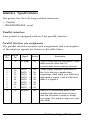
The printer has the following resident interfaces:
• Parallel
• RS-232C/RS-422 serial
Parallel interface
Your printer is equipped with an 8-bit parallel interface.
Parallel interface pin assignments
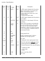
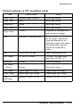
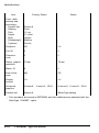
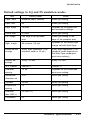
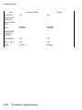
The parallel interface connector pin assignments and a description
of the interface signals are shown in the table below.
Signal Return
Pin
Pin
Signal
Direction
Description
1
19
STROBE
IN
The STROBE pulse to read data in. Pulse
width must be more than 0.5
microseconds at the receiving terminal.
2
3
4
5
6
7
8
9
20
21
22
23
24
25
26
27
DATA
DATA
DATA
DATA
DATA
DATA
DATA
DATA
IN
IN
IN
IN
IN
IN
IN
IN
These signals represent information of
the 1st to 8th bits of parallel data,
respectively. Each signal is at HIGH level
when data is logical 1 and at LOW level
when it is logical 0.
10
28
ACKNLG
OUT
About a IO-microsecond pulse. LOW
indicates that data has been received
and that the printer is ready to accept
more data. This signal is output as a pair
with BUSY.
1
2
3
4
5
6
7
8
Technical Specifications 8-9