1
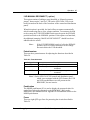
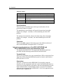
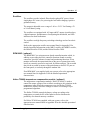
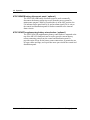
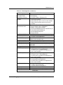
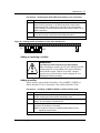
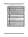
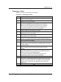
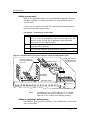
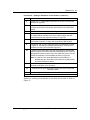
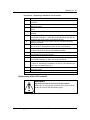
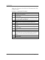
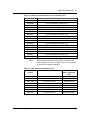
Maintenance 51 Table 30 – Fault diagnosis ( continued ) Fault symptom Failure to generate an RFA alarm under appropriate conditions Rectifiers are not sharing the load Possible causes Faulty rectifier Faulty wiring Faulty RFA MIN or RFA MAJ LED Incorrect float or equalize adjustment on one or more of the rectifiers Sense leads are open on one or more rectifiers Share mode incorrectly set on one or more rectifiers LVD contactor does not Incorrect LVR or LVDR threshold setting reconnect the load Faulty controller card or RPM1000C Blown F1 fuse on the controller (NT6C14GA/GB/GM and NT6C14GE/GF/GP) or LVD (NT6C14GC/GD/GN and NT6C14GG/GH/GQ) card Faulty contactor On NT6C14GA/GM and NT6C14GP control and distribution panels only: LV ALM lamp is lit Low discharge voltage condition Incorrect LV level adjustment TST BYPASS lamp is lit The NORMAL/BYPASS switch is in the BYPASS position on the controller card. On NT6C14GC/GN control and distribution panels only: UNIT lamp is lit red Failure of the RPM1000C UNIT lamp is flashing Low voltage on the memory back-up battery of the RPM1000C AC lamp is lit AC supply for the rectifiers has failed. FLOAT lamp is lit yellow Slightly high or low discharge voltage condition Incorrect HF or LF level adjustment Incorrect float or equalize level adjustment on one or more rectifiers FLOAT lamp is lit red High or low discharge voltage condition Incorrect HV or LV level adjustment Incorrect float or equalize level adjustment on one or more rectifiers BOD lamp is lit Low discharge voltage condition Incorrect BOD level adjustment Incorrect float or equalize level adjustment on one or more rectifiers HVSD lamp is lit A high voltage shutdown signal was sent to the rectifiers by the RPM1000C Incorrect HVSD level adjustment FAN lamp lit Fan failure on one or more rectifiers AUX lamp lit Auxiliary equipment failure (when programmed) continued Emerson Energy Systems MFA150 Power SystemNT6C28C User Manual