1
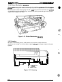
EPSON TERMINAL PRINTER
n
As
tyhs
TN
COLOR
SERVICE MANUAL
-.
EPSON
4003353
.
c’
-. -
NOTICE
All rights reserved. Reproduction of any part of this manual in any form whatsoever without
SEIKO EPSON’s express written permission is forbidden.
The contents of this manual are subjects to change without notice.
All efforts have been made toensurethe accuracy of the contents of this manual. However, should
any errors be detected, SEIKO EPSON would greatly appreciate being informed of them.
The above notwithstanding SEIKO EPSON can assume no responsibility for any errors in this
manual or the consequence thereof.
Epson and Epson EsC/l? are registered trademark of Seiko Epson Corporation.
General Notice: Other product names used herein are for identication purposes only and may be
trademarks of their respective campanies.
@Copyright 7994 by SEIKO EPSON CORPORATION Nagano, Japan
..
C
3
“1
-i-
PRECAUTIONS
Precautionary notations throughout the text are categorized relative to 1) personal injury and 2)
damage to equipment.
DANGER
Signals a precaution which, if ignored, could result in serious or fatal personal injury.
Great caution should be exercised in performing procedures preceded by DANGER
Headings.
WARNING Signals a precaution which, if ignored, could result in damage to equipment.
The precautionary measures itemized below should always be observed when performing repair/
maintenance procedures.
DANGER
1.
ALWAYS DISCONNECT THE PRODUCT FROM BOTH THE POWER SOURCE AND
PERIPHERAL DEVICES PERFORMING ANY MAINTENANCE OR REPAIR PROCEDURE.
2.
NO WORK SHOULD BE PERFORMED ON THE UNIT BY PERSONS UNFAMILIAR WITH
BASIC SAFETY MEASURES AS DICTATED FOR ALL ELECTRONICS TECHNICIANS IN
THEIR LINE OF WORK.
3.
WHEN PERFORMING TESTING AS DICTATED WITHIN THIS MANUAL, DO NOT
CONNECT THE UNITTOA POWER SOURCE UNTIL INSTRUCTED TO DO SO. WHEN
THE POWER SUPPLY CABLE MUST BE CONNECTED, USE EXTREME CAUTION IN
WORKING ON POWER SUPPLY AND OTHER ELECTRONIC COMPONENTS.
WARNING
1.
REPAIRS ON EPSON PRODUCT SHOULD BE PERFORMED ONLY BY AN EPSON
CERTIFIED REPAIR TECHNICIAN.
2.
MAKE CERTAIN THAT THE SOURCE VOLTAGE IS THE SAME AS THE RATED VOLTAGE, LISTED ON THE SERIAL NUMBER/RATING PLATE. IF THE EPSON PRODUCT
HAS A PRIMARY AC RATING DIFFERENT FROM AVAILABLE POWER SOURCE, DO
NOT CONNECT IT TO THE POWER SOURCE.
3.
ALWAYS VERIFY THAT THE EPSON PRODUCT HAS BEEN DISCONNECTED FROM
THE POWER SOURCE BEFORE REMOVING OR REPLACING PRINTED CIRCUIT
BOARDS AND/OR INDIVIDUAL CHIPS.
4.
IN ORDER TO PROTECT SENSITIVE MICROPROCESSORS AND CIRCUITRY, USE
STATIC DISCHARGE EQUIPMENT, SUCH AS ANTI-STATIC WRIST STRAPS, WHEN
ACCESSING INTERNAL COMPONENTS.
5.
REPLACE MALFUNCTIONING COMPONENTS ONLY WITH THOSE COMPONENTS
BY THE MANUFACTURE; INTRODUCTION OF SECOND-SOURCE ICS OR OTHER
NONAPPROVED COMPONENTS MAY DAMAGE THE PRODUCT AND VOID ANY
APPLICABLE EPSON WARRANTY.
- ii -
PREFACE
This manual describes functions, theory of electrical and mechanical operations, maintenance, and repair
of Stylus Color.
The instructions and procedures included herein are intended for the experience repair technician, and
attention should be given to the precautions on the preceding page. The chapters are organized as
follows:
CHAPTER 1. PRODUCT DESCRIPTION
Provides a general product overview, lists specifications, and illustrates the main components of the printer.
CHAPTER 2. OPERATING PRINCIPLES
Describes the theory of printer operation.
CHAPTER 3. DISASSEMBLY AND ASSEMBLY
Includes a step-by-step guide for product disassembly and assembly.
CHAPTER 4. ADJUSTMENTS
Includes a step-by-step guide for adjustment.
CHAPTER 5. TROUBLESHOOTING
Provides Epson-approved techniques for adjustmen~
CHAPTER 6. MAINTENANCE
Describes preventive maintenance techniques and lists lubricants and adhesives required to seMce the equipment.
APPENDIX
Describes connector pin assignments, circuit diagrams, circuit board component layout and exploded diagram.
The contents of this manual are subject to change without notice.
-
iv -
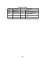
REVISION SHEET
Revision
Page /Contents
Issue Date
1 st issue
Rev.-A
April 27, 1994
Rev.-B
October 4, 1994
3-1
Change the WARNING contents
Rev.-C
November 30, 1994
3-3
Change the explanation for the
upper case removal
Rev.-D
January 11, 1995
4-7 to 4-17
-v-
Incorporate the simple adjust
method.
TABLE OF CONTENTS
CHAPTER 1.
CHAPTER 2.
CHAPTER 3.
CHAPTER 4.
CHAPTER 5.
CHAPTER 6.
APPENDIX
PRODUCT DESCRIPTION
OPERATING PRINCIPLES
DISASSEMBLY AND ASSEMBLY
ADJUSTMENTS
TROUBLESHOOTING
MAINTENANCE
-
vi -
Chapter 1
Product Description
Table of Contents
1.1 FEATURES
1-1
1.2 SPECIFICATIONS
1-2
Printing Specifications. . . . . . . . . . . . . . . . . . . . . . . . . . . . . . . . . . . . . . .
Paper Handling Specifications. . . . . . . . . . . . . . . . . . . . . . . . . . . . . . . . .
Paper Specifications . . . . . . . . . . . . . . . . . . . . . . . . . . . . . . . . . . . . . . . .
Ink Cartridge Specifications. . . . . . . . . . . . . . . . . . . . . . . . . . . . . . . . . . .
Electrical Specifications. . . . . . . . . . . . . . . . . . . . . . . . . . . . . . . . . . . . . .
Environmental Conditions . . . . . . . . . . . . . . . . . . . . . . . . . . . . . . . . . . . .
1.2.7 Reliability . . . . . . . . . . . . . . . . . . . . . . . . . . . . . . . . . . . . . . . . . . . . . . . . .
1.2.8 Safety Approvals. . . . . . . . . . . . . . . . . . . . . . . . . . . . . . . . . . . . . . . . . . .
1.2.9 Physical Specifications . . . . . . . . . . . . . . . . . . . . . . . . . . . . . . . . . . . . . .
1.2.1
1.2.2
1.2.3
1.2.4
1.2.5
1.2.6
1-2
1-4
1-4
1-6
1-7
1-7
1-8
1-8
1-8
1-9
1.3.1 Serial Interface Specifications . . . . . . . . . . . . . . . . . . . . . . . . . . . . . . . . . 1-9
1.3.2 Parallel Interface Specifications. . . . . . . . . . . . . . . . . . . . . . . . . . . . . . . 1-11
1.3 INTERFACE SPECIFICATIONS
1.4 OPERATIONS
1.4.1 Control Panel... . . . . . . . . . . . . . . . . . . . . . . . . . . . . . . . . . . . . . . . . . .
1.4.2 Panel Operation atPowerOn . . . . . . . . . . . . . . . . . . . . . . . . . . . . . . . .
1.4.3 Default Settings. . . . . . . . . . . . . . . . . . . . . . . . . . . . . . . . . . . . . . . . . . .
1.4.3.1 Default Setting Items. . . . . . . . . . . . . . . . . . . . . . . . . . . . . . . . .
1.4.3.2 Changing the Default Settings. . . . . . . . . . . . . . . . . . . . . . . . . .
1.4.4 ErrorConditions. . . . . . . . . . . . . . . . . . . . . . . . . . . . . . . . . . . . . . . . . . .
1.4.5 Printer Initialization . . . . . . . . . . . . . . . . . . . . . . . . . . . . . . . . . . . . . . . .
1.4.5.1 Hardware lnitiaiization. . . . . . . . . . . . . . . . . . . . . . . . . . . . . . . .
1.4.5.2 Software Initialization . . . . . . . . . . . . . . . . . . . . . . . . . . . . . . . .
1.4.5.3 Panel initialization. . . . . . . . . . . . . . . . . . . . . . . . . . . . . . . . . . .
1-12
1-12
1-13
1-14
1-14
1-15
1-17
1-17
1-17
1“17
1-17
1.5 MAIN COMPONENTS
1-18
1.5.1 Main Control Board (C137 MAIN Board). . . . . . . . . . . . . . . . . . . . . . . . 1-18
1.5.2 Power Supply Board (C137 PSB/PSE Board). . . . . . . . . . . . . . . . . . . . 1-19
1.5.3 Control Panel (C137 PNL Board) . . . . . . . . . . . . . . . . . . . . . . . . . . . . . 1-19
1.5.4 Printer Mechanism (M-4AIO). . . . . . . . . . . . . . . . . . . . . . . . . . . . . . . . . 1-20
1.5.5 Housing . . . . . . . . . . . . . . . . . . . . . . . . . . . . . . . . . . . . . . . . . . . . . . . . . 1-20
Rev.A
l-i
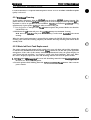
List of Figures
Figure 1-1. Exterior View of the Stylus Color. . . . . . . . . . . . . . . . . . . . . . . . . . . 1-1
Figure 1-2. Nozzle Configuration. . . . . . . . . . . . . . . . . . . . . . . . . . . . . . . . . . . . 1-2
Figure 1-3. Printable Area for Cut Sheet. . . . . . . . . . . . . . . . . . . . . . . . . . . . . . 1-5
Figure 1-4. Printable Area for Envelope . . . . . . . . . . . . . . . . . . . . . . . . . . . . . . 1-5
Figure 1-5. Adjust Lever . . . . . . . . . . . . . . . . . . . . . . . . . . . . . . . . . . . . . . . . . . 1-6
Figure 1-6. Temperature/Humidity Range. . . . . . . . . . . . . . . . . . . . . . . . . . . . . 1-7
Figure 1-7. Data Transmission Timing . . . . **9* **89 am8*, *s8, *a8ame 1,, 1-9
Figure 1-8. Control Panel Appearance . . . . . . . . . . . . . . . . . . . . . . . . . . . . . . 1-12
Figure 1-9. C137 MAIN Board Component Layout . . . . . . . . . . . . . . . . . . . . . . 1-18
Figure 1-10. C137 PSB/PSE Component Layout . . . . . . . . . . . . . . . . . . . . . . 1-19
Figure 1-11. C137 PNL Board Component Layout . . . . . . . . . . . . . . . . . . . . . 1-19
Figure 1-12. Printer Mechanism (M-4A1O) . . . . . . . . . . . . . . . . . . . . . . . . . . . 1-20
Figure 1-13. Housing. . . . . . . . . . . . . . . . . . . . . . . . . . . . . . . . . . . . . . . . . . . . 1-20
●
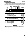
List of Tables
Table 1-1. Interface Cards. . . . . . . . . . . . . . . . . . . . . . . . . . . . . . . . . . . . . . . . . 1-1
Table 1-2. Print Speed and Printable Columns. . . . . . . . . . . . . . . . . . . . . . . . . 1-2
Table 1-3. Character Tables . . . . . . . . . . . . . . . . . . . . . . . . . . . . . . . . . . . . . . . 1-3
Table 1-4. Cut Sheet Paper Specifications. . . . . . . . . . . . . . . . . . . . . . . . . . . . 1-4
Table 1-5. Envelope Specifications. . . . . . . . . . . . . . . . . . . . . . . . . . . . . . . . . . 1-4
Table 1-6. Adjust Lever Setting. . . . . . . . . . . . . . . . . . . . . . . . . . . . . . . . . . . . . 1-6
Table 1-7. Rated Electrical Ranges. . . . . . . . . . . . . . . . . . . . . . . . . . . . . . . . . . 1-7
Table 1-8. Acceptable Environmental Conditions. . . . . . . . . . . . . . . . . . . . . . . 1-7
Table 1-9. Signal and Connector Pin Assignments for Parallel Interface . . . . 1-10
Table 1-10. DTR and X-ON/X-OFF Protocol. . . . . . . . . . . . . . . . . . . . . . . . . . 1-11
Table 1-11. Signal and Connector Pin Assignments for Serial Interface. . . . . 1-11
Table 1-12. Default Setting Items . . . . . . . . . . . . . . . . . . . . . . . . . . . . . . . . . . 1-14
Table 1-13. Characteristics of Print Direction Mode . . . . . . . . . . . . . . . . . . . . 1-14
Table 1-14. Printing Direction and ESC U Command. . . . . . . . . . . . . . . . . . . 1-14
Table 1-15. Language Selection . . . . . . . . . . . . . . . . . . . . . . . . . . . . . . . . . . . 1-15
Table 1-16. Feature Selection. . . . . . . . . . . . . . . . . . . . . . . . . . . . . . . . . . . . . 1-15
Table 1-17. Character Table Selection . . . . . . . . . . . . . . . . . . . . . . . . . . . . . . 1-16
Table 1-18. Error Indications. . . . . . . . . . . . . . . . . . . . . . . . . . . . . . . . . . . . . . 1-17
l-ii
Rev. A
c-.,
Product Description
Stylus Color Service Manual
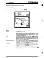
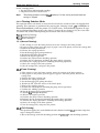
1.1 FEATURES
The Stylus Color is a 64- + 48-nozzle (monochrome and CMY) color ink jet dot matrix printer that
uses new ink jet technology to achieve high-quality, high-speed printing. The major features of this
printer are:
Q Highquality color printing as a result of new inkjet technology.
Cl Fast print speeds, capable of printing LQ characters at
\ 200 cps.
D Compact design to save precious work space.
c1
Built-in auto sheet feeder with a maximum capacity of 100 cut sheets, 50 transparencies,
70 heavy or special papers, or 10 envelopes.
tl
8-bit parallel interface and Macintosh@ serial interface standard.
Easy setup.
Four scalable fonts and five LQ fonts standard.
c1
L1
c1
L1
Support for 9 character tables in the standard version and 15 character tables in the NLSP
(Na~ional Language Support Printer) version.
Inexpensive to run and maintain.
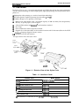
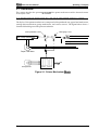
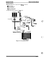
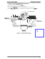
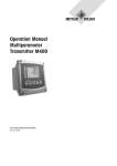
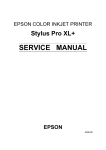
The figure below shows the Stylus Color.
paper
feeder,
cover
/h ~
paper
separators
knob
\“
paper
supporl
parollel
interface
k \(A~i.,et)
Figure 1-1. Exterior View of the Stylus Color
Table 1-1. Interface Cards
I
Interface Card
I
Model Number
I serial interface card
I C823051/C823061
I 32KB serial interface card
I C823071/C823081
I 32KB parallel interface card
I C82310*
I 32KB IEEE-488 interface card
\ C82313*
I LocalTalk@ interface card
I C82312*
ITwinax interface card
I C82315*
I Coax interface card
I C82314*
* The asterisk is a substitute for the Iastdigit, which varies bycountty.
Rev. A
1-1
stylus
Product Description
color sdwvk Msnual
1.2 SPECIFICATIONS
This section provides statistical facts and other detailed intonation for the printer.
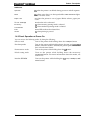
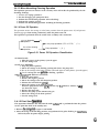
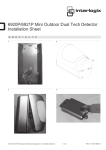
1.2.1 Printing Specifications
Print system:
On demand inkjet system
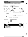
Nozzle configuration:
64 nozzles ($ x 4 staggered): Monochrome
4$ nozzles (16x 3 staggered): Color
Row D :
Magenta
Cyan
Yellow
’“0
t
1/90”
i #2
Q“-”--”-”””-
-“”o”#-2-”””---e---e
Row
8 ~ f?ow A
s
-.4
+
g
- 721360”
0.
.
.$. . . . . . . . . . . . . . . . . . . . . . . . . . . . . . . . . . . . . . . . . . . . . . . . . . . . . . . . . . . . --6 *I ‘- ““”
,,36(J* -- .-.. --;.. ----------------& 2-------------- .................. +...... ------------t
:il 3
tQ . . . . . . . . . . . . . . . . . . . . . . . . . . . . . . . . . . . . . . . . . . . . . . . . . . . . . . . . . . . . . . . . . . . . . . . . . . . . . :
1/90’
i---------. ---"" ----i--" ----.. --"-. ----" ----------------6 -;4--------------; I
:--.------;-------------- __-+___..~#5 ..*_.
--”:--- --- -:
..() #l . .
~’
Row C
#2
. . . . .4. . . .
-6;6 ------J87----::---""---------------"----------------.--.--!#8--------.-.----i
. . . .. . . . . .. ... ... . .. . .... . .... . ... . ...
Q-.-......-:
#3
“0:3
““
“o
: ----- .
64/360”
v #16
*#16
V #16
o
0
-.....0861
“-”’”--”’-” “--””;-”””””-”
‘-“0---=’------””
-------+
--------”
‘#63”
o - ‘“ ’ --------- ‘- - --0864-- - --
0
““””’viii”””-”””-
Figure 1-2. Nozzle Configuration
Printingdirection:
Bidirectionalwithlogic-seeking
Printspeed:
SeeTable l-2.
Printable columns:
SeeTable l-2.
TabIe l-2. Print Speed and Printable Columns
CharacterPitch
1-2
I
PrintableColumns
I
Print Speed(LQ)
I
I
IOcpi (Pica)
15cpi
120
3oocps
L
I
17cpi (Picacondensed)
137
340cps
20cpi(Eiitecondensed)
160
4oocps
12cpi (Elite)
I
1
60
96
I
1
2oocps
240cps
Rev.A
Product Description
Sty/us Co/or Service Manual
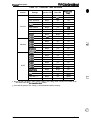
Character sets:
Legal and 14 international character sets.
Character tables:
See Table 1-3.
Table 1-3. Character Tables
Standard
Version
NLSP* Version
PC437 (U.S./Standard Europe)
PC850 (Multilingual)
o
0
o
0
o
0
PC860 (Portuguese)
o
x
PC861 (Iceland)
o
x
PC863 (Canadian-French)
o
x
PC865 (Nordic)
o
x
PC437 (Greek)
x
O (Note)
PC852 (East Europe)
x
O (Note)
PC853 (Turkish)
x
O (Note)
PC855 (Cyrillic)
x
O (Note)
PC857 (Turkish)
x
O (Note)
Character Tables
Italic
PC866 (Russian)
I
1
PC869 (Greek)
MAZOWIA (Poland)
x
x
I
ISO 8859-7 (Greek)
ISO Latin IT (Turkish)
I
I
O (Note)
1
x
Code MJK (Czechoslovakia)
O (Note)
O (Note)
x
O (Note)
I
x
x
I
I
O (Note)
O (Note)
Bulgaria (Bulgaria)
x
O (Note)
Abicomp
o
o
x
BRASCII
o supported
Note:
X
Not SUpported
Language Support Printer
These fonts are not supported for EPSON Roman Tand EPSON Saris Serif H of scalable
Fonts:
Bitmap LQ fonts
- EPSON Roman
- EPSON Saris Serif
- EPSON Courier
- EPSON Prestige
- EPSON Script
Control code:
Input data buffer:
Rev. A
* National
x
(10 cpi/12 cpi/15 cpi/Proportional)
(10/12/15/Proportional)
(10/12/15)
(10/12/15)
(10/12/15)
Scalable fonts
- EPSON Roman
10.5 points, 8 -32 points (in units of 2 points)
- EPSON Saris Serif
10.5 points, 8 -32 points (in units of 2 points)
- EPSON Roman T
10.5 points, 8-32 points (in units of 2 points)
- EPSON Saris Serif H 10.5 points, 8-32 points (in units of 2 points)
ESC/P 2 and expanded raster graphics code
64K bytes
1-3
Ptvduct
!wJdus color Sefvkw Mmu8/
&SCf@th
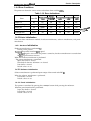
1.2.2 Paper Handling Specifications
Friction feed paper is fed from the built-in auto sheet feeder (ASF).
Feeding method:
Notes: The following operations are not allowed.
1. Reverse feeding within 3 mm (O. 12in.) from the top edge of the paper or 16mm
(0.63 in.) from the bottom edge of the paper.
2. Reverse feeding beyond 7.9mm (0.3in.).
1/6 inch feed, 1/8 inch feed, or programmable with a 1/360 inch minimum
Line spacing:
increment.
Paper path:
Cut sheet: Built-in auto sheet feeder (ASF) (front entry)
Feeding speed:
89 msec. (at l/6-inch feed pitch)
1.2.3 Paper Specifications
Table 1-4. Cut Sheet Paper Specifications
Size (W x L)
I
Thickness
A4:
210 mm (8.3 in.) x 297 mm (1 1.7 in.)
Letter:
216 mm (8.5 in.) x 279 mm (1 1.0 in.)
B5:
182 mm (7.2 in.) x 257 mm (10.1 in.)
Legal:
216 mm (8.5 in.) x 356 mm (14.0 in.)
I 0.08 mm (0.003 in.) -0.11 mm (0.004 in.)
Weight
55 g/m2 (17 lb) -90 g/m2 (24 lb)
Qualitv
Bond paper. PPC
Table 1-5. Envelope Specifications
I
I No. 6:
Size (W x L)
No. 10:
I DL:
Thickness
166 mm(6½ in.) x 92 mm (3 % in.)
240 mm(91A in.) x 104mm(41A in.)
220 mm (8.7 in.) x 110 mm (4.3 in.)
] Less than 0.52 mm (0.020 in.)
Weight
75 g/m2 (20 lb) -90 g/m2 (24 lb)
Qualitv
Bond Paper
Note:
1-4
Envelope printing is supported onfy at room temperature.
When inserting envelopes, keep the longer side honzontal.
Rev. A
Product Description
Stylus Color Service Manual
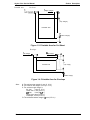
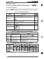
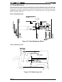
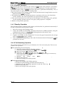
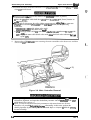
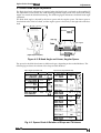
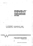
Printable area:
Cut sheet
c
(Right margin~
A
(Top margin)
Printable area
D
(Bottom margin)
i
Figure 1-3. Printable Area for Cut Sheet
Envelope
B
(Left margin)
c
B
-P
(Right margin)
Printable area
B
&
A
(Top margin)
D
(Bottom margin)
Figure 1-4. Printable Area for Envelope
Note:
Rev. A
A: The minimum top margin= 3 mm (0. 12 in.)
B: The minimum left margin= 3 mm (O. ?2 in.)
C: The minimum right margin is:
3 mm (O. 12 in.)
A4 size:
Letter size: 9 mm (0.35 in.)
3 mm (0. 12 in.)
i35 size:
Legal size: 9mm (0.35 in.)
Envelope: 3 mm (0.12 in.)
D: The minimum bottom margin= 13 mm (0.51 in.)
1-5
Stylus Color Service Ahnual
Product Descfhtion
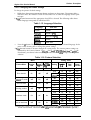
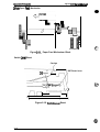
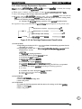
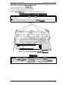
Adjust lever setting: The adjust lever on the carriage unit must be set to the proper position for
the paper thiclmess, as shown m Table 1-6.
Table 1-6. Adjust Lever Setting
Lever Position
Paper
Paper Thickness
LEFT
(Vertical)
Cut Sheet
0.08-0.11 mm
(0.003 -0.004 in.)
RIGHT
(Horizontal)
Envelope
Less than 0.5 mm (0.020 in.)
Carriage Umt
I
e
~ Adjual Lever
Figure 1-5. Adjust Lever
1.2.4 Ink Cartridge Specifications
Black
Type:
Exclusive cartridge
Color:
Black
Print capacity:
1 million characters (315 dots/character, Roman IOcpi)
3
The effective life from the indicated production date is 2 years.
Life:
Storage temperature:
Dimension (W x D x H):
-30- 40° C (–22 - 104° F) (Storage, within a month at 40° C (104° F))
-30- 60° C (-22 - 140° F) (Transit, within a month at 40° C (104° F))
–30 - 60° C (–22 - 140” F) (Transit, within 120 hours at 60° C (140°
F))
26.9 x67.4 X 41.8 mm (1.06 x2.65 X 1.65 in.)
color
Type:
Exclusive cartridge
Color:
Cyan, Magenta, Yellow
Print capacity:
28 sheets/color (A4, Full image printing at 360 dpi)
Life:
The effective life from the indicated production date is 2 years.
Storage Temperature:
-30- 40° C (–22 - 104° F) (Storage, within a month at 40° C (104° F))
-30- 60° C (–22 - 140° F) (Transit, within a month at 40° C (104° F))
–30 - 60° C (–22 - 140” F) (Transit, within 120 hours at 60° C (140°
F))
54.0 X 67.4X 41.8 mm (2.13 X 2.65X 1.65 in.)
Dimension (W x D x H):
Notes:
1-6
- Ink cartridge cannotbe re-tiled; it is the onlywnsummable article.
- Donotuse an inkcarlndge thathas exceededtheink/ife.
- Ink freezes below-~ C; however, itcan be usedafieritmfums to room temperature.
Rev. A
-%
c
Product Description
Stylus Color Service Manual
1.2.5 Electrical Specifications
Table 1-7. Rated Electrical Ranges
I
Item
120 V Version
I
220-240 V Version
120 VAC
220-240 VAC
103.5-132 V
198-264 V
Rated frequency range
50-60 Hz
50-60 Hz
Input frequency range
49.5 -60.5 Hz
49.5 -60.5 Hz
Rated voltage
Input voltage range
I
Rated current
I
0.6 A
0.4 A
Power consumption
Approx. 20 W
Approx. 20 w
(self-test with 10-cpi LQ characters) (self-test with 10-cpi LQ characters)
Insulation resistance
10 Mf2, minimum
10 MQ, minimum
(applying 500 VDC between AC line (applying 500 VDC between AC line
and chassis)
and chassis)
1000 VAC rms -1 minute or
1200 VAC rms -1 second
(between AC line and chassis)
Dielectric strength
1500 VAC rms -1 minute
(between AC line and chassis)
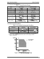
1.2.6 Environmental Conditions
Table 1-8. Acceptable Environmental Conditions
Description
Temperature
Operating
Non Operating
10- 35° c (50 - 95° F) “
–20 - 60° C (-4 - 122° F) ● 2
20- 80!%0 RH ● ’73
5- 85% RH “2’3
IG (within 1 rnsec.)
2G (within 2 msec.)
0.15 G
0.50 G
Humidity
Shock resistance
Vibration resistance
2
:1: For operating the pn”nter, conditions must be in the range shown in the figure below.
,2: These conditions are acceptable when the printer is in its shipping container.
3
: Without condensation.
Humidity
(% RH)
:
...........
80!!0
Guara,nleed range
...........
55?40
20?40 . . . . . . . . . . .
I
Io”c
(50”F)
27°C 35°C
(80°F) (95°F)
‘c
(“F)
Figure 1-6. Temperature/l=lumidity Range
Rev. A
1-7
stylus Colar &wvke Msnusl
Product Llsscriptkm
1.2.7 Reliability
MTBF:
4JIO0 power on hour (pOH)
Total print volume:
Printhead life:
75,0(X) pages (A4, Letter)
1$00 million dots/nozzIe
1.2.8 Safety Approvals
Safety standanis:
120V version:
22@240V version:
Radio frequency interference (RFI):
120V version:
220-240V version:
UL1950 with D3,
CSA22.2 #950 with D3
EN 60950 ~, SEMKO, DEMKO,
NEMKO, SETI)
FCC part 15 subpart B class B
Vfg.243 (VDE0878 part 3, part 30)
EN55022 (CEPR PUB. 22) class B
1.2.9 Physical Specifications
Dimension (W x D x H):
470 X 525X 192 (mm) (18.5X 20.7X 7.56 (in.))
Weight
7.4 Kg (163 lb)
1-8
.-
( \
Rev. A
Product Description
Stylus Color Service Manual
1.3 INTERFACE SPECIFICATIONS
The Stylus Color is standard-equipped with an 8-bit parallel and serial interface.
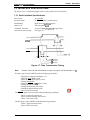
1.3.1 Serial interface Specifications
Data format:
8-bit parallel
Synchronization:
By STROBE pulse synchronization
Handshaking:
By BUSY and ACKNLG signals
Signal level:
TTL compatible level
Adaptable connector:
36 pin 57-30360 (Amphenol) or equivalent
Data transmission timing:
See Figure 1-7.
BUSY
ACKNLG
DATA
STROBE
L.&
L_- 0.5 ps (minimum)
0.5 IJS (minimum)
0.5 ps (minimum)
Figure 1-7. Data Transmission Timing
Note:
Transition time (rise time and fall time) of every input signal must be less than 0.2 ps.
The Busy signal is active (HIGH) under the following conditions:
- During data reception (See Figure 1-7.)
- When the input buffer is full
- When the INIT input signal is active
- During initialization
- When the ERROR or PE signal is active
- During the self-test mode
- During the demonstration mode
- During the default setting mode
- When a fatal error occurs
The ERROR signal is active (LOW) under the following conditions:
- When a paper-out error occurs
- When a no ink cartridge error occurs
- When a fatal error occurs
The PE signal is active (HIGH) under the following conditions:
- When a paper-out error occurs
- When a fatal error occurs
Rev. A
1-9
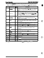
Table 1-9 shows the co nm@or pin assignments and signal functions of the 8-bit parallel interface.
Table 1-9. Signal and Connector Pin Assignments for Parallel Interface
Signal Name
Pin No.
1
2-9
*
STROBE
DATA 1-8
I/o’
Description
I
The STROBE pulse is used to read data from the host
computer. The pulse width must be 0.5 ~ or more. Normally,
it is HIGH, and data is latched with the rising edge of this
signal.
I
DATA 1-8 are parallel data bits. When one of these signals is
HIGH, the data bit is 1; when LOW, the data bit is O. The most
significant bit (MSB) is DATA 8. The signal state must be
maintained for 0.5 ps on either side of the STROBE signal’s
active edge.
10
ACKNLG
o
ACKNLG is an acknowledge pulse with a width of
approximately 10 p.s. This signal goes LOW upon the
completion of data reception to indicate that the printer is
ready to receive further data.
11
BUSY
o
The BUSY signal informs the host computer of the printer’s
status. When this signal is HIGH, the printer cannot accept
any more data.
12
PE
o
This signal indicates whether paper is available in the printer
or not. A HIGH level indicates no paper.
13
SLCT
o
Pulled up to +5V through a 1.0 KQ resistor in the printer.
14
AFXT
I
If this signal is set to LOW, the printer automatically performs
one line feed upon receipt of a CR (carriage return) code. The
status of this signal is checked onty at power on and
initialization.
31
m
I
If this signal goes LOW, the printer is initialized. The pulse
width of this signal must be 50 @ or more.
32
ERROR
o
This signal goes LOW if the printer has a fatal error or runs
out of paper.
35
+5V
17
CHASSIS
16
GND
-
19-30
-
.
Signal ground.
.
33,36
-
.
Not USed.
Pulled up to +5V through 1.0 KQ resistor in the printer.
Chassis ground.
c,. .
2
15,18,34 —
7he //0 column indicates the direction of the signal as viewed hm the printe~
1-1o
Rev. A
Product Description
Stvlus Color Service Manual
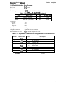
1.3.2 Parallel Interface Specifications
Data format:
RS-422 serial
Synchronization:
Asynchronous
Handshaking:
By DTR signal and X-ON/X-OFF protocol
Table 1-10. DTR and X-OIVX-OFF Protocol
Buffer Space
DTR
X-OWX-OFF
Busy
Less than 512 bytes
off
X-OFF
Ready
More than 1,024 bytes
On
X-ON
State
Word length
Start bit:
Data bit:
Parity bit:
Stop bit:
1 bit
8 bit
none
1 bit
Bit rate:
57.6K bps
Adaptable connector:
8-pin mini-circular connector
Recommended I/F cable:
Apple@ System Peripheral-8 cable
Table 1-11. Signal and Connector Pin Assignments for Serial Interface
Pin No.
Signal Name
I/o’
1
DTR
out
2
NC
3
TXD
out
Transmit data
4
SG
In
Signal ground
5
RXD
In
Receive data
6
TXD
out
7
NC
8
RXD
Description
Data terminal ready
No connection
Balanced transmit
No connection
In
Balanced receive
* The 1/0 column indicates the data flow as viewed from the printer.
Rev. A
1-11
stylus COW SerVke Aww4d
Product LMscriptkw
1.4 OPERATIONS
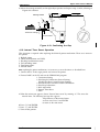
This section describes the basic operations of the printer.
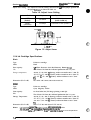
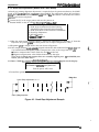
1.4.1 Control Panel
The control panel for this printer has 1 lock type, 5 ncm-lock type push buttons, and 14 LED
indicators for easy operation of the various printer functions.
Un
J Courier
Cl Operate
U Data
O Pap9r Out
No Ink Cartridge
Font
Alt
c
I
3 Romau T (PS)
3 Saris Serif H (PS)
m
Z Roman
3 Saris Serif
;$s’ige
m
Cl Pause
I
IR eset
Figure 1-8. Control Panel Appearance
Buttons
Operate
Turns the printer on or off.
Att
Modifies the function of other buttons. Holding down this button
for 3 seconds causes the printer to move the carriage to the ink
cartridge installation position. Pressing Ait again causes the carriage
to return to the home position.
Font
Cycles through the font choices. pressing the F~t button, while
holding down the AH button causes the carriage to move to the gap
adjustment position. Pressing the AN button again causes the
carriage to return to the home position.
Economy/Condensed
Selects either the economy printing or mndensed printing mode.
Pressing the Economy/Condensed button while holding down
the Alt button starts the color printhead cleaning cycle.
Load/Eject
Either loads a new sheet into the printer or ejects paper currently in
the paper path. Pressing the L~d/E@t button while holding down
the Alt button starts the black printhead cleaning cycle.
Pause
Stops printing temporarily or resumes printing if it has been
stopped temporarily. Pressing Pause while holding down the Alt
button resets the printer.
~.
L
ma,.
A
‘,
.;
1-12
Rev. A
Product Description
Stvlus Color Se fvice Manual
Indicators
Operate
On when the printer is on. Blinks during power on and off sequence.
Data
On when print data is in the input buffer. Data and Pause lights
blink if an error occurs.
Paper Out
On when the printer is out of paper. Blinks when a paper jam
occurs.
No Ink Cartridge
On when the ink is exhausted.
Economy
On when economy printing mode is selected.
Condensed
On when condensed printing mode is selected.
Font
These LEDs indicate the selected font.
Pause
On when printing is paused.
1.4.2 Panel Operation at Power On
You can activate the following modes by doing the following:
Self-test mode
Turn on the printer while holding down the Load/Eject button.
Hex dump mode
Turn on the printer while holding down the Font and Load/Eject
buttons. Once this mode is selected, the printer prints all received
data in hexadecimal format.
Demonstration mode
Turn on the printer while holding down the Alt button.
Default setting mode
Turn on the printer while holding down the E c o n o m y /
Condensed button. For more information about the mode, see
Section 1.4.3.
Initialize EEPROM
Turn on the printer while holding the Alt, Font, Load/Eject, and
Pause buttons.
Rev. A
1-13
St’jms Cokw SawicO ManUd
Product Oesct’iptkm
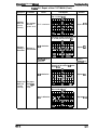
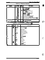
1.4.3 Default Settings
The printer can save some printer setting parameters that define its functions at initializatkn. You
can change these parameters by using the printer’s default setting mode.
e
1.4.3.1 Default Setting Items
You can use the det%ult setting mode to change the settings listed in the table below. Activate the
default-setting mode by holding down the Economy/Condensed button while turning on the
printer.
Table 1-12. Default Setting Items
Menu
Contents
mct31111
Description
Character table
Selects the character table
.
Print direction
Controls the print direction. (See Tables 1-12 and 1-13)
Auto
Bi-D
Uni-D
.
Network l/F mode
Off: For normal environments.
On: For network environments.
Auto line feed
On: Valid
Off: Invalid
Loading position
3.0/8.5 mm (0.12/0.33 in.)
Interface mode
Auto I/F mode
Parallel l/F mode
Seriil l/F mode
Optional l/F mode
Auto l/F wait mode
1 0/30 seconds
off
.
3.0 mm
.
10 sec.
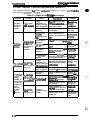
Table 1-13. Characteristics of Print Direction Mode
ttem
I
Black and White Printing
I
Color (CMYK) Printing
Auto
Throughput and quality is
better.
Throughput is better.
Color quality with special paper is WOW.
(Color correction depends on the printing direction.)
Bi-D
Throughput is best.
Print quality may be down.
Throughput is better.
Color quality with special paper is worse.
(Color correction depends on the printing direction.)
Uni-D
Throughput is worse.
Print quality is better.
Throughput is worse.
Color quality is best.
Table 1-14. Printing Direction and ESC U Command
Auto
l)efaul:~~tting
r
Bi-O
Uni-D
ESC UO ESC U1 None ESC UO ESC UI None ESC UO ESC U1 None
Character mode
(for MS-DOS?
Auto
Auto
Auto
Bi-D
Uni-D
Bi-D
Uni-D
Uni-D
Uni-D
Raster graphics
mode (fo~
Vvindows )
Bi-D
Uni-D
Auto
Bi-D
Uni-D
Bi-D
Bi-D
Uni-D
Uni-D
Note:
1-14
*
Printing ditection is controlkdby dtiverin IMndows entimnment
Rev. A
Product Description
Stylus Color Service Manual
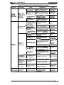
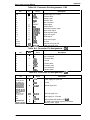
1.4.3.2 Changing the Default Settings
To change the printer’s default settings:
a.
Hold down the Economy/Condensed button and turn on the printer. The printer pMts a
sheet that shows the firmware version and describes how to select the language used to print
messages.
b. Press the Font button until the appropriate font LED is selected. The following table shows
which language corresponds to which font LED.
Table 1-15. Language Selection
Font LED
Language
c.
English
Courier
Fran~is
Roman T (PS)
Deutsch
Saris Serif H (PS)
Italiana
Roman
Espafiol
Saris Serif
Press the Alt button. The printer prints the current settings using the selected language. It also
prints a table showing how to change the printer settings.
d. Press the Font button to advance through the setting menu. The current printer settings are
indicated by the Courier, Roman T (PS)~and San Se;if H (PS) LEDs. Ead”time you pr&s the
Font button, you adance to the next setting, and the three font LEDs change according to the
selection.
Table 1-16. Feature Selection
Menu
Feature/Menu
Courier
LED
Character table
On
Print direction
Vetwork l/F mode
On
off
Setting Value
I
Saris
Roman T Serif
H
(PS) LED (ps) LED
On
off
I
I
I
On
On
off
I
Auto
Bi-D
Uni-D
off
On
off
Auto line feed
On
On
off
Loading position
off
off
On
I
On
off
Auto l/F wait time
off
On
On
I
I
On
off
On
off
1
I
off
On
Paper
Out LED
I
r
1
off
off
off
On
off
off
On
off
+
off
off
off
On
off
3 mm
8.5 mm
off
On
off
off
off
off
Auto
On
off
off
off
On
On
off
off
Option
I
I
Data
LED
off
off
Parallel
Serial
On
i
See Table 1-16
off
On
interface mode
O ED
rate
r
Setting
I
I
10 sec.
30 sec.
On
I Off
off
On
off
1
1
off
off
On
off
off
e. Change the setting value by pressing Alt button. Pressing the Alt button changes the setting
for the current menu. The status of the LEDs will be changed as the button is pressed, -
Rev. A
1-15
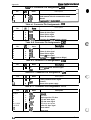
Sty#Us Cokw ~ Mllnuul
Pfvduct Description
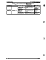
Table 1-17. Character Table Selection
Version
Operate LED
Data LED
Pa~hr)ut
off
On
off
m
Off
off
Blinks
off
off
Italic U.K.
Off
On
off
ttalic Denmark 1
On
On
off
Blinks
Off
Off
Settings
Italic U.S.A.
Italic France
Italic Germany
Common
Standard
NLSP
Italic Sweden
Italic Italy
off
On
Blinks
Italic Spain 1
On
Blinks
oft
PC437
PC850
Blinks
Blinks
Off
off
off
on
PC860
On
off
On
PC863
PC865
Blinks
off
off
On
on
PC861
On
On
BRASCII
Blinks
On
On
On
Abicomp
PC437 Greek
PC853
off
off
Blinks
Blinks
On
off
Off
On
on
PC855
off
On
on
PC852
On
On
on
PC857
Blinks
On
on
PC866
off
Blinks
On
PC869
On
Blinks
on
MAZOWIA
Blinks
Blinks
On
Code MJK
1s0 8859-7
off
On
off
off
Blinks
Blinks
ISO Latin IT
Blinks
off
Blinks
Bulgaria
c.,
:-l.
.t “
on
,’
G.-
off
On
Blinks
f. Repeat d and e to change other printer settings. The setting menu selection will return to the
first menu after the lastmenu *l@ion is over.
g. Turn off the printer. The setting is stored intonon-volatile memory.
1-16
.c. ;
Rev. A
Product Description
Sty/us Color Service Manual
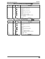
1.4.4 Error Conditions
The printer can detect the various errors and indicate them with the LEDs.
Table 1-18. Error Indications
f
Data LED
Pa~;rDOut
No Ink
Catiridge
LED
Paper out
off
On
off
off
off
off
No ink cartridge
off
off
On
off
off
off
Paper jam
off
Blinks
off
off
off
off
Error
Ecm~my Con&sed
Pfg~
,,4#R
Maintenance request
Blinks
Blinks
Blinks
Blinks
Blinks
Blinks
Carriage error
Blinks
off
off
off
off
Blinks
#KG@$4 L
1.4.5 Printer Initialization
There are three initialization methods: hardware initialization, software initialization, and panel
initialization.
1.4.5.1 Hardware Initialization
Hardware initialization is performed by:
Turning on the printer.
- %mdin~ the parallel interface INIT signal.
(If the INIT signal is active when the printer is turned on, hardware initialization is started when
the INIT signal becomes inactive.)
When the hardware initialization is performed:
- The printer mechanism is initialized.
Input data buffer is cleared.
Downloaded character definitions are cleared.
Print buffer is cleared.
Default values are set.
1.4.5.2 Software Initialization
Software initialization is performed upon receipt of the control code ESC @.
When the software initialization is performed:
Print buffer is cleared.
Default values are set.
1.4.5.3 Panel Initialization
This printer is initialized by pressing the Load/Eject button while pressing the Alt button.
When the panel initialization is performed:
Input data buffer is cleared.
Print buffer is cleared.
Default values are set.
Rev. A
1-17
-
—
Product Descriptkm
.
—
.
-
.
--
.
- Color Setvke hfg@g##
1.5 MAIN COMPONENTS
The main components of the Stylus Color are:
Q Printer mechanism (M-4A10)
Q Main control board (C137 MAIN Board)
Cl Power supply unit(C137PSB/PSE Board)
Q Control panel board (C137PNL Board)
Q Housing
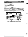
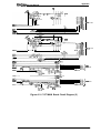
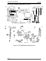
1.5.1 Main Control Board (C137 MAIN Board)
The Main Control Board (C137 MAIN Board) consists of an H8/3003 l~bit CPU, E05A% gate
array, a program ROM (4M), a dynamic RAM (4M), a mask ROM (4M or 8M), an EEP-ROM (lK),
and a lithium battery for powering the protect counters. The reset IC (M51955 and ~ 592) is
equipped with both a logic system and a power system. The 8M program ROM is used only fix the
NJ.5P (National Language Support Printer) specification.
IC14 SLA7041 1
~ .ICl!i SI A7041
z~
. . . . . . . .,.
CN2
,“
I
1
f-l
m
—
.,
“
—
c)
z
0
-
RM12
RM11
/
Q14
#—————— K
CN1
i
\@
I
BAT 1
Figure 1-9. C137 MAIN Board Component Layout
(., “
1-18
Rev. A
Product Description
Stylus Color Service Manual
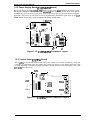
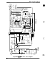
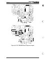
1.5.2 Power Supply Board (C137 PSB/PSE Board)
The Power Supply Board (C137 PSB/PSE Board) consists of an RCC switching regulator circuit.
This board is equipped with a power switch comected to the secondary circuit. Thus, if the printer
is turned off, it can continue to operate in order to eject the paper and perform the head capping
operation. The power on/off signal is always monitored by the E05A96 gate array on the C137
MAIN Board, and the logic system recognizes the power switch status.
j-- IC51 (TL494)
CN2 ,
:-
n
I
. .; Q51
J
–Qo aa (@r
u
,
I
– cl
c~
cl
1-
—
1-
DB1 C3
L1
Figure 1-10. C137 PSB/PSE Component Layout
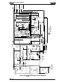
1.5.3 Control Panel (C137 PNL Board)
The 14 LEDs on this board indicate the error status (there is no buzzer system); by using the
6 switches in combination with one another, the printer can operate in each protect operation (color
or black cleaning, cartridge exchanging self-test, default setting value exchanging, reset, and
EEP-ROM clear operation).
SW6
t
t
❑
q
LED1
1---1
I
/
LED4
LED8
0 LED5
0 LED6
/-
LED14
[It
0 I
m7
SW4
Ill
M
:0°
i-l
‘
m
●
/
Swo
n
0
‘0
—
I
Figure 1-11. C137 PNL Board Component Layout
Rev. A
1-19
Product D9sctiptk3n
Stylus Color *vim Manual
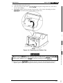
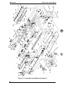
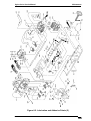
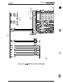
1.5.4 Printer Mechanism (M-4A1O)
The M-4A1O printer mechanism is equipped with a 64-black printhead and M-color (CMY)
printhead on the carnage unit. Resolution of 720 dpi is possible with special (non-absorbent) paper.
The ink system has both a black pump unit and a coIor pump unit. Waste ink from each printhead
is made to flow into the individual caps. Power for the pump system and paper feed system is
supplied from the paper feed motor.
-—
‘.,
Figure 1-12. Printer Mechanism
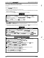
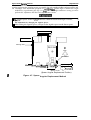
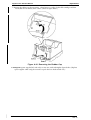
1.5.5 Housing
The Stylus Color housing consists of the printer cover, uppercase, and the lowercase.
Attached to the housing are the front paper support
ejected paper support with paper
separator.
1
I
c
II
mH
4
4
r
1
A
L
km
L
L- upper Case
Lower Case
Figure 1-13. Housing
1-20
‘,
-.-7
Rev. A
Chapter 2 Operating Principles
Table of Contents
2.1 OVERVIEW
2-1
2“1
Printer Mechanism. . . . . . . . . . . . . . . . . . . . . . . . . . . . . . . . . . . . . . . . . . 2-2
Carriage Drive Mechanism . . . . . . . . . . . . . . . . . . . . . . . . . . . . . . . . . . . 2-5
2.2.2.1 Platen GapAdjust Lever . . . . . . . . . . . . . . . . . . . . . . . . . . . . . . . 2-6
Paper Feed Mechanism. . . . . . . . . . . . . . . . . . . . . . . . . . . . . . . . . . . . . . 2-6
InkSystem. . . . . . . . . . . . . . . . . . . . . . . . . . . . . . . . . . . . . . . . . . . . . . . . 2-8
Pump Mechanism . . . . . . . . . . . . . . . . . . . . . . . . . . . . . . . . . . . . . . . . . . 2-9
Cap Mechanism. . . . . . . . . . . . . . . . . . . . . . . . . . . . . . . . . . . . . . . . . . . 2-12
Wiping Mechanism ..~ . . . . . . . . . . . . . . . . . . . . . . . . . . . . . . . . . . . . . 2-12
2.2 OPERATING PRINCIPLES OF THE PRINTER MECHANISM
2.2.1
2.2.2
2.2.3
2.2.4
2.2.5
2.2.6
2.2.7
2.3 OPERATING PRINCIPLES OF THE ELECTRICAL CIRCUITS
2.3.1 Operating Principles ofthe Power Supply Circuit . . . . . . . . . . . . . . . . .
2.3.2 Operating Principlesofthe Main Control Circuit . . . . . . . . . . . . . . . . . .
2.3.2.1 Reset Circuits.. . . . . . . . . . . . . . . . . . . . . . . . . . . . . . . . . . . . .
2.3.2.2 SensorCircuits. . . . . . . . . . . . . . . . . . . . . . . . . . . . . . . . . . . . .
2.3.2.3 Carriage MotorDriveCircuit . . . . . . . . . . . . . . . . . . . . . . . . . . .
2.3.2.4 Paper Feed Motor Drive Circuit. . . . . . . . . . . . . . . . . . . . . . . . .
2.3.2.5 Printhead Drive Circuit . . . . . . . . . . . . . . . . . . . . . . . . . . . . . . .
2.3.2.6 DMAControlier. . . . . . . . . . . . . . . . . . . . . . . . . . . . . . . . . . . . .
2.3.2.7 D-RAM Refreshment Controller. . . . . . . . . . . . . . . . . . . . . . . . .
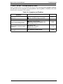
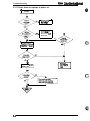
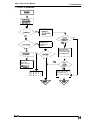
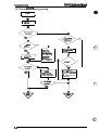
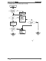
2.4 INK SYSTEM MANAGEMENT
2.4.1 InkOperations. . . . . . . . . . . . . . . . . . . . . . . . . . . . . . . . . . . . . . . . . . .
2.4.1.1 PowerOnOperation. . . . . . . . . . . . . . . . . . . . . . . . . . . . . . . . .
2.4.1.2 Cleaning Selection Mode . . . . . . . . . . . . . . . . . . . . . . . . . . . . .
2.4.1.3 Micro Absorbing Cleaning Operation . . . . . . . . . . . . . . . . . . . .
2.4.1.4 PowerOffOperation . . . . . . . . . . . . . . . . . . . . . . . . . . ,..,.,
2.4.1.5 Print Start Operation . . . . . . . . . . . . . . . . . . . . . . . . . . ,.,,..
2.4.1.6 Refresh Operation . . . . . . . . . . . . . . . . . . . . . . . . . . . . . . . . . .
2.4.1.7 Standby Operation . . . . . . . . . . . . . . . . . . . . . . . . . . . . . . . . . .
2.4.1.8 Fail Absorbing Operation . . . . . . . . . . . . . . . . . .m.,m, ,,..,.
2.4.1.9 Ink Cartridge Replacement Operation . . . . . . . . . . . . . . . . . . . .
2.4.1.10 Wiping Operation 1 . . . . . . . . . . . . . . . . . . . . . . . . . . . . . . . . .
2.1.4.11 WipingOperation2 . . . . . . . . . . . . . . . . . . . . . . . . . . . . . . . .
2.4.1.12 Rubbing Operation . . . . . . . . . . . . . . . . . . . . . . . . . . . . . . . . .
2.4.1.13 Disengage ON Operation . . . . . . . . . . . . . . . . . . . . . . . . . . . .
2.4.1.14 Disengage OFFOperation . . . . . . . . . . . . . . . . . . . . . . . . . . .
2.4.1.15 Micro Absorbing Operation . . . . . . . . . . . . . . . . . . . . . . . . . . .
2.4.1.16 Carriage Lock Set. . . . . . . . . . . . . . . . . . . . . . . . . . . . . . . . . .
2.4.1.17 Carriage Lock Reset. . . . . . . . . . . . . . . . . . . . . . . . . . . . . . . .
2.4.1.18 Refresh Operation (Performed when loading or
ejecting paper) . . . . . . . . . . . . . . . . . . . . . . . . . . . . . . . . . . . .
2.4.1.19 Adjust Lever Operate Position Moving Sequence. . . . . . . . . .
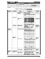
2.4.2 TimerandCounter. . . . . . . . . . . . . . . . . ....._...;.. . . . . . . . . . . . . .
2.4.2.1 Refresh Timer (Monochrome and CMY Head) . . . . . . . . . . . . .
2.4.2.2 Timer (Monochrome and CMY Head). . . . . . . . . . . . . . . . . . ,.
2.4.2.3 Flushing Counter (Black, CMY Head). . . . . . . . . . . . . . . . . . . .
Rev. A
2-13
2-13
2-15
2-16
2-16
2-17
2-19
2-20
2“21
2-22
2-23
2-24
2-24
2-25
2-26
2-26
2-26
2-27
2-27
2-27
2-28
2-29
2-29
2-29
2-29
2-29
2-30
2-30
2-30
2-30
2-30
2-30
2-30
2-31
2-31
2-i
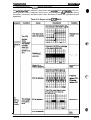
2.4.2.4 Fail Absorbing Timer (Black, CMy Head) . . . . . . . . . . . . .....2-31
2.4.2.5 Ink Level Counter R (On the RAM)
(Monochrome = Rb, CMY = Ry) . . . . . . . . . . . . . . . . . . . . .. ..2-31
2.4.2.6 CL Counter K (Monochrome = Kb, CMY = Ky) . . . . . . . . . . . . . 2-32
k.
@
2.4.2.7 CL2 Counter KK (Monochrome = KKb, CMY = KKy). . . . . . . . . 2-32
2.4.2.8 Protect Counter. . . . . . . . . . . . . . . . . . . . . . . . . . . . . . . . . . . . . 2-32
List of Figures
Figure 2-1. Printer Mechanism Block . . . . . . . . . . . . . . . . . . . . . ...........2-1
Figure 2-2. Structure of Printhead. . . . . . . . . . . . . . . . . . . . . . .............2-2
Figure 2-3. Principles of the Printing Operation. . . . . . . . . . . . . . . . . . . . . .. ..2-3
Figure 2-4. Microwave Mode Operation . . . . . . . . . . . . . . . . . . . . . ........2-4
Figure 2-5. Carriage Drive Mechanism . . . . . . . . . . . . . . . . . . . . . . . . . . . . . . . 2-5
Figure 2-6. Platen Gap Lever Operation. . . . . . . . . . . . . . . . . . . . . . . . . . . . . . 2-6
Figure 2-7. Paper Feed Mechanism . . . . . . . . . . . . . . . . . . . . . ............2-7
Figure 2-8. Ink System Block . . . . . . . . . . . . . . . . . . . . . .................2-8
Figure 2-9. Pump Mechanism Block. . . . . . . . . . . . . . . . . . . . . . ...........2-9
Figure 2-10. Switch Lever Set. . . . . . . . . . . . . . . . . . . . . . . . . . . . . . . . . . . . . . 2-9 f~l
Figure 2-11. Paper Feed Mechanism Block . . . . . . . . . . . . . . . . . . . . . . . . . . 2-IO ‘-=
Figure 2-12. Switch Lever Reset. . . . . . . . . . . . . . . . . . . . . . . . . . . . . . . . . . . 2-10
Figure 2-13. Pump Operation . . . . . . . . . . . . . . . . . . . . . . . . . . . . . . . . . . . . . 2-11
Figure 2-14. Cap Mechanism . . . . . . . . . . . . . . . . . . . . . . . . . . . . . . . . . . . . . 2-12
Figure 2-15. Wiping Mechanism . . . . . . . . . . . . . . . . . . . . . . . . . . . . . . . . . . . 2-12
Figure 2-16. Block Diagram of the Electrical Circuit . . . . . . . . . . . . . . . . . . . . 2-13
Figure 2-17. Power Supply Circuit Block Diagram. . . . . . . . . . . . . . . . . . . . . . 2-14
Figure 2-18. Main Control Circuit Block Diagram . . . . . . . . . . . . . . . . . . . . . . 2-15
Figure 2-19. Reset Circuit Block Diagram. . . . . . . . . . . . . . . . . . . . . . . . . . . . 2-16
Figure 2-20. Sensor Circuit Block Diagram. . . . . . . . . . . . . . . . . . . . . . . . . . . 2-16
Figure 2-21. Carriage Motor Circuit Block Diagram. . . . . . . . . . . . . . . . . . . . . 2-17
Figure 2-22. Serial Data Transfer Procedure. . . . . . . . . . . . . . . . . . . . . . . . . . 2-18
Figure 2-23. Paper Feed Motor Drive Circuit Diagram . . . . . . . . . . . . . . . . . . 2-19
Figure 2-24. Trapezoidal Drive Wave Form. . . . . . . . . . . . . . . . . . . . . . . . . . . 2-20
Figure 2-25. Printhead Drive Circuit Block Diagram . . . . . . . . . . . . . . . . . . . . 2-20
Figure 2-26. DMA Controller Operation. . . . . . . . . . . . . . . . . . . . . . . . . . . . . . 2-21 -.
f~.Figure 2-27. D-RAM Cycle Timings. . . . . . . . . . . . . . . . . . . . . . . . . . . . . . . . . 2-22
Figure 2-28. Junction Method (CPU-DRAM). . . . . . . . . . . . . . . . . . . . . .. ...2-22
Figure 2-29. Relation of Ink System & Carriage Operation. . . . . . . . . . . . . . . 2-23
Figure 2-30. Power On Operation Classification. . . . . . . . . . . . . . . . . . . . . . . 2-24
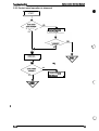
Figure 2-31. Power Off Operation Classification. . . . . . . . . . . . . . . . . . . . . . . 2-26
Figure 2-32. Ink Cartridge Replacement Classification . . . . . . . . . . . . . . . . . . 2-28
List of Tables
Table 2-1. Carriage Drive Motor Specifications. . . . . . . . . . . . . . . . . . . . . .. ..2-5
Table 2-2. Drive Terms . . . . . . . . . . . . . . . . . . . . . . . . . . . . . . . . . . . . . . . . .. .2-5
Table 2-3. Platen Gap Adjust Lever Position. . . . . . . . . . . . . . . . . . . . . . . . . . . 2-6
Table 2-4. Paper Feed Drive Motor Specification . . . . . . . . . . . . . . . . . . . . .. .2-6
Table 2-5. Drive Terms. . . . . . . . . . . . . . . . . . . . . . . . . . . . . . . . . . . . . . . . . .. 2-7
Table 2-6. Pump Mechanism Operation . . . . . . . . . . . . . . . . . . . . . . . . . . . . . 2-11
Table 2-7. DC Voltage Distribution . . . . . . . . . . . . . . . . . . . . . . . . . . . . . . . . . 2-13
Table 2-8. Serial Data contents . . . . . . . . . . . . . . . . . . . . . . . . . . . . . . .....2-17
Table 2-9. Paper Feed Motor Drive Modes. . . . . . . . . . . . . . . . . . . . . . .....2-19
Table 2-10. Junction Method (CPU-2CAS DRAM) . . . . . . . . . . . . . . . . . . . . .2-22
2-ii
Rev. A
C,?,
*U)
Stylus Color Service Manual
Operating Principles
2.1 OVERVIEW
This section describes the operating prinaples of the printer mechanism and the electrical circuits
of the Stylus Color.
2.2 OPERATING PRINCIPLES OF THE PRINTER MECHANISM
The Stylus Color printer mechanism is composed of the printhead unit, paper feed mechanism,
carriage drive mechanism, pump mechanism, and various sensors. The figure below shows a
functional block diagram of the printer mechanism.
Disengage Lever
Pickup Release Lever
~p
Pa er Feed Mechanism
\
ASF Pickup Mechanism
A A
4+
..
..
..
...
..
.
.
Pump Unit Drive Mechanism I
●
●
●
■
●
.
.
●
●
.
s
n
)
\P
/
Paper Feed Motor
●
.
,
.
.
.
.
*“”””-”””””J
..
:.
●
●
Unit
Carriage Motor
Color Black
Figure 2-1. Printer Mechanism
Rev. A
2-1
sty/ua Cubf S9wke Manual
Opfating Pfincipies
2.2.1 Printer Mechanism
The printer mechanism of this printer uses a dropmnde-d inkjet system similar to the system
used on all other EPSON ink jet printers. However, the printhead in this system is mmpletely
redesigned to make it more mmpact and ensure a high level of reliability. The figure below shows
the structure of the printhead and ink supply system.
■ M-L-P
MLP is the abbreviation for Multi-Layer Piezoelectric element. When a drive pulse
(voltage) is applied, this element pushes the vibration plate, compressing the cavity
fix ink injection from the nozzle.
~ Cavity
Ink supplied from the ink cartridge is stored in this space and is injected from the
nozzles when the vibration plate compresses this area.
■ Nozzles
These inject ink against the paper’s surface in response to the application of the
print signaL Them are 64 (black head) or 48 (color head) individual nozzles making
up the printhead.
Printhead driver board
Cartridge needle
\
/
Fi
,avi,~et~’L~ti,.YerPiezo)
(nozzle)
>Nou’e
Nozzle plate
nk supply tank
Vibration plate
0
‘
MLP
(Multi-layer piezo)
Figure 2-2. Structure of Printhead
2-2
Rev. A
Operating Principles
Stylus Color Service Manual
Principles of the Printing Operation
The printhead operates in one of two modes to inject ink from each nozzle:
■ Normal state
No electrical charge is applied to the MLP (Multi-Layer Piezoelectric) element attached to the
back of the cavity, and pressure inside the cavity is kept at a constant level.
■ Injecting state
The head data signal is applied to the specific nozzle control line to select the active nozzle for
printing, and the MLP element is gradually charged by the drive voltage. By charging the MLP
element, the vibration plate is bent to compress the cavity. Then, ink is injected from the
nozzle.
Nozzle
Normal
state
Nozzl
Injectir Ig
state
@
Figure 2-3. Principles of the Printing Operation
When the ink charge or printhead cleaning operation is performed, the ink in the cavity is
vacuumed out with the pump mechanism. During printing, on the other hand, the ink is
simultaneously supplied from the ink cartridge and injected from the nozzle, according to the
change of volume in the cavity.
A thermistor is attached to the side of the color printhead drive board to monitor the temperature
because the viscosity of the ink varies, depending on the temperature. The detected temperature
level is fed back to the printhead drive voltage control circuit to change the time of the Tc pulse.
(The Tc pulse is shown in Section 2.3.2.5.)
Rev. A
2-3
Sryhs color Sewka #anuaf
Op9mthg Principks
The Stylus Color printer has a special printing mode, called microwave mode, for printing raster
graphics. This printing mode can be selected from the custom driver. Using the microwave mode
can improve the quality of output because it elimina tes the banding that can sometimes Occurin
normal mode. In microwave mode, the paper feed ogration is performed after each print pass,
thus eliminating the pitch variation as the paper feed that causes the banding.
Microwave print mode is available for both 360-and 720dpi resolution.
■ Normal mode
Normally the printer uses all nozzles for printing and each print line is completed in one pass.
But if the image data contains both monochrom e and color in a single print line, the printer
pMts the line in four passes even for monochrome printing ( 1/360 x 4 line fked), because if
the image data contains color in a single print line, it uses only 16 nozzles in row A of the black
head.
S Microwave mode
In microwave mode, the printer pMts the whole image as a single image rather than as
continual lines. In this mode, the printer uses only 15 nozzles of row A of the nozzles (#1 to
#lS). After printing the first pass, the printhead moves to a new position 15/360 inch forward.
The printer repeats this sequence until it finishes printing the whole image. In microwave
mode the printing starts from the under nozzle (#57 pin).
...
W S*
Ist Stec)
#1
#5
2
n
,,
,.
,.
,.
,.
,
,.
I
#57
#29
#45
1/90 inch
Lino Feed DirWion
#33
#49
1/360 (1/720) inch line feed
1/360”
t
#37
#53
r
,!
:
(,
I
Paper (bottom side)
I
#41
#57
Final Steo
d
(#61 Not Uaad) I
2rfd Stef)
-k
5
I
I
#57
#29
#45
#13
#33
#49
#17
#37
#53
821
#41
#57
#57
1/120”
#45
1/90”
#49
F
#53
#57
Figure 2-4. Microwave Mode Operation
2-4
Rev. A
.
Opefating Principles
Stylus Color Service Manual
2.2.2 Carriage Drive Mechanism
The timing belt attached to the base of the carriage unit is driven by the carriage motor, causing the
carriage unit to move along the carnage guide shaft left to right, or vice versa. The carriage drive
motor on this printer is a 4-phase, 200-pole, hybrid-type stepping motor mechanism, allowing the
printer to stop the carriage or change the carriage movement at any position. The position of the
carriage is recognized by the home position sensor, and position information is fed back to the
carriage drive control circuit. This carriage motor is driven by the motor driver IC SLA7041 (see
Section 2.3.2.3 for more information).
Table 2-1. Carriage Drive Motor Specifications
I
I
Item
Description
I
I 4-phase/ 20C)-pole hybrid-type stepping motor
Motor Type
Drive Voltage
+35 VDC t 5?40
Coil Resistance’
10.0 Q f 7940
Drive Frequency
960-4800 PPS
I
I
I Constant current unipdar Drive, Micro Step Driving
Excitation Mode
In the following table, 2W1-2 phase means the 1/8 2-2 phase drive control. ( ) is the value of 2-2
phase.
Table 2-2. Drive Terms
Phaee Drive Method
ACCJ
CR Speed
Frequency
Mode 1
~200 ~ps)
4800(2400)
■ Acc./Deceleration Area: 2WI-2 phase + 1-2
phase
■ Constant Area: 1-2 phase
Ace. 40(5)+1 10(55)
Dec.32(4)+1 12(56)
Mode 2
(loo Cps)
2400(1200)
■ Acc./Deceleration Area: 2WI-2 phase + 1-2
phase
■ Constant Area: 1-2 phase
40(5)+40(20)
Mode 3
(40 CPS)
‘60(480)
Q Acc./Deceleration Area: 2WI-2 phase
■ Constant Area: 2W1-2 phase
Deceleration
Step
16(2)
CR, . Motor
...
klul c)
Figure 2-5. Carriage Drive Mechanism
Rev. A
2-5
Sty/us Co/of Sefvice Manual
Operating Pffncipk3s
2.2.2.1 Platen Gap Adjust Lever
The platen gap adjust Iever, which is attached to the carriage unit, needs to be set to an appropriate
oosition for the Paper thickness. To change the platm gap, put the printer in the PAUSE state, then
~ress the Font&& while holding dm& the-Alt button; the carriage unit moves the platen gap
adjustment position automatically.
Table 2-3. Platen Gap Adjust Lever Position
I Paper Type
Horizontal (A) (*O mm)
Cut sheet
I Vertical (B) (+0.6 mm)
I Envelope
r
/’ - -., -+ -
.r . . - -.*
Lever Position
I
1
Platen Gap Adjust Lever
\
,,., ,- ., - - - - - - - . .1
(A)
,.
.
.0
●
I
,*,
**
.,.
.,,
,,
,,
.,,
*,,
\ ‘,
\,
\,
t,
‘,- :\
.= - -
‘
,,$
,,$
\
‘,
--”
(B)
---.
t . - - . .- - - . .. .
.“
,
.
.
.-
.
I
,
- .-> . — . x— — .
.:.
.
i-----+
,
,
.
‘.
—
‘.
.
-.
.
‘
.*
.,
*,
$,
●,
.
,
L. -...)
,
.
..
:
. .,-.
,
,
.
~
.,’
0.6mm gap
-—
—. —-. —-—.—-—.—-
(Plain paper, Bond ~r)
(Envelop or Transparency)
Figure 24. Platen Gap Lever Operation
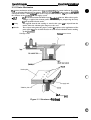
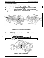
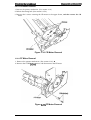
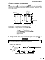
2.2.3 Paper Feed Mechanism
~s printer’s paper feed mechanism can fked paper only fkom the built-in ASF (auto sheet feeder).
The paper feed drive motor is a 4-phase, 96-pole, hybrid-type stepping motor that directly drives
the paper &d mdwnism (paper advancing operation, paper pick-up operation). This motor also
drives the pump mechanism, but only when the printer is in the cleaning state. The paper feed
drive method is driven by the 2-2 phase drive method, except the paper feed drive sequerm
(2W1-2 phase).
Table 2-4. Paper Feed Drive Motor Specification
I
Item
Dssodption
Motor Type
4-phase, 96-pole, hybrid-type
Drive Vottage
+35 VDC * 5?0
I Coil Resistance
Drive Frequency
Excitation Mode
24
I
I 11.5 Q*I.lQ
I
I
300-1600 PPS
I Paper feed/ Pump clrive: 2-2 phase, 2W1-2 phase
I
Rev. A
Stylus Color Service Manual
Operating Principkw
Table 2-5. Drive Terms
Mode
Frequency
(PP$$)
Current Value (mA)
AccJDcce.
Constant
Rush
Hold
Paper loading
1600
970/750
750
750
240
ASF feed
1600
970/750
750
750
240
Paper feed
391
-/-
970
Pump Drive 1
1800
1380/1380
1380
750
240
Pump Drive 2
300
-/-
1380
.
240
240
PF Pinch Roller Unit
ickup Roller
Paper
pF Motor Pinion
Platen Driie Gear
Paper Pickup Lever=
Tension
Cam Roller Hopper
Figure 2-7. Paper Feed Mechanism
Rev. A
2-7
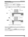
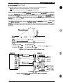
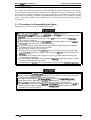
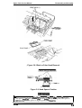
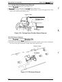
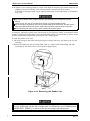
2.2.4 Ink System
This printer’s ink system is composed of the fbllowing mechanisms:
W Ink cartridge
■ Pump mechanism
■ Cap mechanism
■ Waste ink drain tank
■ Wiping mechanism
The figure below shows a diagram of the rnk system.
color head
BM head
1
cleaning Blade
(for a)br/blackhead)
. . .[
..
-,
..........
........
........................
........................
- Friction Clatch
.......
-.................... -.-...., /:... . . . . . . ‘
Pumpl
, /Pullp
sengage Unit
;!:
.~i
;.
-.
::!
!.
.:.
i
*
Um ~
1
~ PFIWX
-
Platen Roller
Pm@
,
-/
J
,.-. . . . . . . . . - . . ,:...
. . . . . . . . . . . . . . . . . .- .- . .
/“
Figure 2-8. Ink System Block
24
Rev. A
Operating Principbs
Stylus Color Service Manual
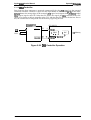
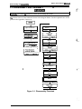
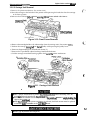
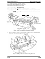
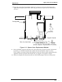
2.2.5 Pump Mechanism
The paper feed motor drives the pump mechanism when the transmission gear is moved to the
position where the paper feed motor disengages the pump mechanism gear trains, when the
carriage unit is at the ink system home position. The figure below shows a block of the pump
mechanism. Pump system operation depends on the rotational direction of the paper feed drive
motor, as shown in Table 2-6.
Drive: Pump Mechanism
................................
Carriage
p
...........................
LB
Hook
Spring
INN
r
1
Release
LClatnh
I===t
,-.”,
---. . . . -.
%
:.;....: .,...:.: .... :.
3~.: .:
PF Motor
...................
lump Unit
Figure 2-9. Pump Mechanism Block
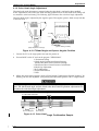
Drive: Switch Lever Set
~arriage
h-+
D/E Reset Lever
p--l
1—1 D/E Set Lever
/(
D/E Lever
\
I
1
‘------------ I ~ \
1
L.
\
H
l— ) ~1
Figure 2-10. Switch Lever Set
Rev. A
2-9
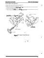
sty/us COk# ~ M9nu81
Opmtlng Princ@8s
Wve: Paper I%?@ Mechanism
e
\
A
- - - - - - - - - - - - - - - - - - - - - - - - - - - - - - - - -
canaige
‘. . . . - . . . . . - . . . - . - . . . . . .- . . .
L.
....~.....
.
..
.,
.
:.:... ..::.. ..:
3
.
.
:.:.:$:.:.:.
............
.
.
.
.
.
.
:.:.:.:.:.:.
b.,
Figure
..................
Paper Feed Mechanism Block
Switch Let&: Reset
Carriage
DE Lever
\ DIE Reset Lever
I
c.+
..A
--:
‘/
1,
Figure 2-12. Switch
2-10
)
Reset
Rev. A
,
/
Operating Principles
Stylus Co/or Service Manua/
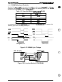
Table 2-6. Pump Mechanism Operation
PF Motor Rotational Direction
I
Operation
CW (forward rotation)
■ Color absorption
9 Color micro absorption
■ Color fail absorption
■ Wiper reset
■ Carriage lock reset
CCW (backward rotation)
■ Monochrome absorption
H Monochrome micro absorption
■ Monochrome fail absorption
■ Wiper set
■ Carriage lock set
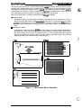
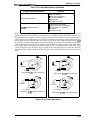
The pump draws ink from the printhead nozzles and drains it into the waste ink drain tank. The
printer performs this operation to eliminate dust or bubbles within the nozzles. Figure 2-13
illustrates the pump operation. When the paper feed drive motor rotates CW (forward), the color
pulley pumps in the wheel pump unit rotate in the direction of the arrow while squeezing the ink
tube to push the ink inside the tube out to the waste ink drain tank. When the motor rotates CCW
(backward), the black pulley pumps in the wheel pump unit rotate in the direction of the arrow
while squeezing the ink tube to push the ink inside the tube out to the waste ink drain tank. There
are 2 pump rollers in the pump unit, and the drive power is supplied from the paper feed motor
via the pump drive gear (D/E gear) that is moved by the carriage operation. In the pump unit, the
transmission gear supplies both the black and color pulley, which are rotated by the rotation of the
other.
u
//
Ink draining
I
*
Vacuuming
Vacuuming
Pump Motor (CW) : Color Pumping
0:
1/
Pump Motor (CCW) : Black Pumping
..
//
0:
No ink draining
..-
No ink draining
I
\ \
-.. .
[
0
Q
No vacuuming
No vacuuming
Pump Motor (CW) : Black No Pumping
Pump Motor (CCW) : Color No Pumping
Figure 2-13. Pump Operation
Rev. A
2-11
stylus Co/w MO M9nual
Opemting Princip&s
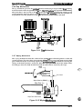
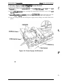
2.2.6 Cap Mechanism
The cap mechanism prevents the printhead nozzles from drying or keeps bubbles horn forming
inside the nozzle while the printer is not in use. The pMter perfimns this operation automatically
when print data is not received or when the printer power is turned off during the printing or ink
system operations. (Since the power switch is equipped with a semndary circuit, this operation cart
be performed.) Also this printer has 2 caps, 1 for the blackhead and 1 for the color head.
Black CartMge
color cartridge
-----
........
...................,
.......................
f ----------............
?
Cap Iiddef
11,. . .
...............................
Capl
Q@
II
Air Vatve _l
Valve spring
Figure 2-14.
-1
Mechanism
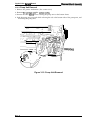
2.2.7 Wiping Mechanism
The wiping mechanism cleans the surface of the printhead nose when the printer is in the ink
system sequence. The wiper drive gear transmits @wer from the paper feed motor via the clutch
gear. When the wiper is raised up (against the printhead surt%ce), the hook for securing the
carriage to the home position is raised, too. When the wiper goes down toward the bottom frame,
the hook goes down, too. Both the black head and the color head are cleaned by this wiper.
-----
-A
-(i -. -. - - - -. -; :
.:”.... . . . . . . . . . . . . . . ..
::
-....0 .
.....................
Wiper(Cleaning blade) —---+
Wiper Drive Gear
~~
1-
Hook Lever
b
1
.-
Platen
Clatch
Wiper Drive Gear Frame
::
,. .-,
i
Figure 2-15. Wiping Mecha6ism
2-12
Rev. A
Opefating Principles
Stv/us Color Service Manual
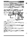
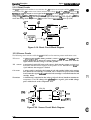
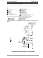
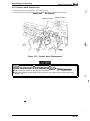
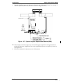
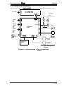
2.3 OPERATING PRINCIPLES OF THE ELECTRICAL CIRCUITS
The Stylus Color contains the following circuit board units:
■ C137MAIN Board (Main control circuit board)
■ C137PSB/PSEBoard (Power supply circuit board)
■ C137PNL (Control panel board)
In addition to the circuit boards above, part of the printhead drive arcuit is built on a separate
circuit board installed in the carriage unit; the printhead is attached directly to this board. The
figure below shows a block diagram of the electrical circuitries.
C137 PNL
,. ..-. . . . . . . . . . . . . . . . . . . . . . . . . . . . . . . . . . . . . . . . . . . . . .
: M-4A1O PRINTER MECHANISM ;
C137 MAIN
C137 PSB/PSE
+5VDC
>
+35VDC ‘
➤
CR/PF Motor
●
j
Carriage Unit ~
~ mm I
. . . . . . R-T02
. . . . . . . . . . Head
. . . . . . . . . . . . . . R-TOI
. -. . . . . . . . . .Head
.........~
Figure 2-16. Block Diagram of the Elecrical Circuit
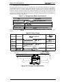
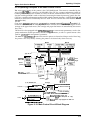
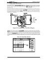
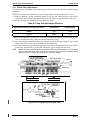
2.3.1 Operating Principles of the Power Supply Circuit
The power supply circuitry for this printer is provided either by the C137 PSB board (120 VAC) or
the C137 PSE board (220-240 VAC). Both boards are identical in design and functionality, except for
the components in the primary circuit that accommodate the specified input voltage. The input
voltage and the application of output voltages are summarized in the table below.
Table 2-7. DC Voltage Distribution
Voltage
+35 VDC
+5 VDC
Rev. A
I
Application
Motor drive (carriage and paper feed)
Printhead (through the drive voltage generation circuit)
C137 MAIN Board
Sensors (home position, paper end, no ink cartridge, head thermistor)
Control panel, head nozzle selector
2-13
stylus Coiaf ~mnwl
Op8fsthg Pfincipks
The figure below shows a block diagram of the power supply circuit (C137 PSB/PSE). The POW=
switch is equipped with a semndary *it that allows the CPU to remain active fbr a while after
the printer is turned off. This allows the printkad to return to the capping position after power has
been turned off. The CPU that is rnowted CXI the C137 MAIN board always monitors the PSC
(Power @/~ sipl. If w signal bemmes ‘ZOW”, the CPU resets -* device * -g
the head capping sequence. Nw, this board employs the RCC (Ringing Choke Coverter) switching
system. This AC voltage is first input to the filter circuit for higher harmoni cs absorption, and then
input to the rectification and smoothing arcuit, converting it into DC voltage. This DC voltage is
then input to the switching arcuit for the swittig operation. Along with the switching operatim
on the primary side, +35 WC is generated after passing through the +35V line voltage detectim
circuit. This +35 VDC output level is stabilized. This +3S VDC is also input to the +5 VDC
generation circuit to generate a stable +5 VDC.
DB1
1
Full-wave
Rectifire Circuit I
L
A
W-@
Filter Circuit
d
F1
Fuse
cl 1
1
r T1
b Smoothing
Circuit
—-T----1
F+13
I
7
Feed back
Circuit
4
)
C51
Smoothing
Circuit
+35 Voc
*
➤
ZD51 , 81-84 ~~
‘
P-off Detection
and delay circuit
ZD86,
C82
ZD52
Over voltage
protection Cir.
A
I
I 1’”1
I It
I
~
I
[
+5 VDC
TL 494
‘hot? I
4
I
ZD53 ,
[Over voltage I
[protection Cir. [
Coupler I
Pcl
P-OFF signal
Hgure 2-17. Power Supply Circuit Biock Diagram
1)+5 VDC line overvoltage protection circuit
The output voltage level of +5V line is monitored by a Zener diode (ZD53). If the voltage level
exceeds +7V, the status is fed back to the primary switching circuit through a photocou pier (-WI)
to stop the +35V generation.
2)+5 VDC line over current/ overvoltage control circuit.
The output current is monitored by a detection resistor (R53) and M back to the +5 VDC
generation switching control IC (IC51), which monitors the output voltage. This inhmation is
input to the internal comparator and outputs the high signal to turn off the transistor (QW) when
the voltage or the current becomes abnormal.
3) +35 VDC line overvoltage protection circuit
The output level is monitored by a Zener diode (ZD36). If the voltage level excwds +36V, a
photocoupler (PCl) is activated; stopping the primary switching circuit operatim.
4) +35 VDC line drop protection circuit
The output level of +35 VDC line is monitored by a detection arcuit that consists of a Zener diode
(ZD51 and ZD81 to 84). This circuit feeds back the output voltage level status through a photm
coupler to the primary switching arcuit to control the ON/OPP time of the switching transistor for
contast output voltage.
2-14
Rev. A
Operating Principles
Sty/us Color Service Manual
2.3.2 Operating Principles of the Main Control Circuit
The main control circuit of this printer is the C137 MAIN board. This circuit is controlled by the
16-bit CPU H8/3003 (ICI), running at 14.7456 MHz. This CPU has a unique architecture capable of
handling data on the data bus at either an 8-bit or 16-bit bus width. Because of this, a 16-bit or 8-bit
data bus width-type ROM is used on this board, increasing the internal processing speed. Also, the
CPU has a unique architecture capable of the refresh control function. A 4M D-RAM (2CAS
method) on this board is controlled by the CPU itself. The CPU controls the serial interface control
(RS-422 for Mac).
Gate array E05A96 (IC2) manages printhead drive control, external Centronics@ parallel I/F,
extension CG board and the control panel, and the controls that create the 4-bit signal for the
carriage or the paper feed motor. (The carriage and paper feed motor are controlled by the current
duty data.)
This board is also equipped with EEPROM 93C46 (IC12) to store certain parameters, such as the
printer mechanism control parameter, default setting parameters, as well as a special counter value
used for printhead (ink management) protection.
The timer IC NJU6355E (IC7) counts each time the printer is cleaned and keeps track of how long
the printer is not used, thereby allowing the printer to be cleared only when necessary.
Note:2
Note:l
mmmm
1
L
1
I
Type B l/F
I
EEPROM I (IC12)
93C46
Reset
(Power)
Reflesh
,7w
I
m
(IC8)
M51955B
RS-422 Seria\W#
E05A96
(IC2)
‘k
H8/3003
(lCl)
4
1
I
I
%---I=+SSB”L”L
54
uru
I
I
I
Pm i
I
(IC13)
Reset
PST592D
(Logic)
Panel
B
DMAREQ
=ery
NJ U6355E
(Timer
J
Counter)
CD
. . . . . . . . . . . . . . . . . . .. ... . . . . . . . . . . . . . . . . . . . . . . . . . . . . . . . . . . .
.Cl
. . . .37
. . . . MAIN
. . . . . . . . .Board
. . . . . . . . . . . . . . . . . . . . . . . . . . . . Carriage
:
I
:,
From A ~ Black/Color head
Common driver Circuit
!
\
:P SED5620
(UI ,U2)
~
➤ Black 64 nozzle ~
; ---- ----- ------ ----- --- -------- ---------- .- .-. . . . . . . . . . . . ..-;
[
From
B
SLA7041MS(IC14,15)
~ ● Carriage/Paper feed
Motor Driver
~
i
Note:l 32-pin IC socket only
(NLSP and European ver. only)
@
Note:2 8M is only equipped in NLSP ver.
. . -. . .- . . . . . . -. . . . .- . -. . . . -. . . . . .- .- . . . . -. . . .,
Figure 2-18. Main Control Circuit Block Diagram
Rev. A
2-15
Sty/us Cc#of &mdce Manual
Opemting Principles
2.3.2.1 Reset Circuits
The C137 MAIN board contains 2 reset circuits: the +5V monitor reset circuit and the +35V monitor
reset circuit. The +5V monitor reset circuit monitors the voltage level of the +5V line, using reset IC
PST592D (IC12), and outputs a reset signal to the E05A96 gate array (IQ when the voltage level
drops below +4.2V. The +35V monitor reset arcuit monitors the voltage level of the +35V line,
using reset IC M51955B (IC8), and outputs a reset signal to the CPU. The reset signal is generated
when the voltage level drops below +28V, and this causes a non-maskable interrupt (NM).
+35V
@
+5V
L
CPU (ICI)
M51 9556
(IC8)
‘6
.
PA8 -# RST
Type B
72• NMI
68+ P62
71 b RES
E05A96 (IC2I
+5V
+
L
1
‘. .,-
@
Figure 2-19. Reset Circuit Block Diagram
2.3.2.2 Sensor Circuits
The following sensor circuits enable the C137 MAW board to monitor printer mechanism status:
HP sensor
A photocoupler-type HP (home position) sensor is attachd to the surfam of the
printer mechanism to detect the carriage home position. A LOW level from the
signal indicates that the carriage is m home position.
PE
A mechanical switch PE (paper end) sensor is built into the printer mechanism to
determine whether there is paper in the printer or not. A LOW level hm the
signal indicates that no paper is loaded.
A micro switch is attached to the bottom of each ink cartridge holder in the carriage
unit. When the ink cartridge is installed, these switches are pressed and a LOW
level from the signal indiates that the ink cartridge is installed into the ink
cartridge holder.
sensor
CO sensor
Thermistor
A thermistor is attached to the color printhead driver board to monitor its
temperature. The CPU changes the print&ad drive signal’s pulse width (charge
pulse width) based on the temperature level.
+5V
+5V
CPU (lCl)
1
(CN8)
[
“
0
Y h~ AN1
2
>
AN5 ● “
86
ANO
HP o ;
(CN9)
[
:
3
AN2 e ~ TH
90
1
AN4 4
-
(CN12)
70 cco-
“ 70 ~~o (CN1l)
I
“: ‘b
h
Figure 2“20. Sensor Circuit Block Diagram
2-16
Rev. A
*.
c;
Operating Principles
Sty/us Color service Manual
2.3.2.3 Carriage Motor Drive Circuit
The carriage motor drive IC SLA7041MS (IC15) outputs a constant current to drive the carriage
motor for the printer mechanism. Gate array E05A96EA (IC2) decides the motor phase and speed
and then sends a signal to the carriage motor driver IC (SLA7041MS) using the 4-bit serial
transmission line.
The first bit indicates the direction of the motor rotation. The other three bits are current duty data
for the motor speed of each printing sequence. SLA7041MS can select the reference voltage itself
based on these three current duty data. Also, it receives these signals by 2 serial transmission lines
for 2 motor’s phases (phase A and phase B). Due to this, the carriage motor can drive the miao step
sequence (min. 1/720 inches).
SLA7041MS
E05A96
(IC15)
(IC2)
CRCLK ~
28
m
.9?‘
m
CRSTB ‘“
13*
CRA
CRB
27
6
25
17
B
CRVRF
(PBO-PB7)
CRHLD
3
a
14
A
L
—
B
w
9
NPN Tr
b (Q27, 28)
CLKA
CLKB
—
STBA
—
STBB
A
b DATA A
K
8
2
* DATA B
~
11
3
➤ REF A
B 18
4
*
1
‘
(CN6)
>
5
m
m4
+
* REF B
● RSA
RSB
E
Figure 2-21. Carriage Motor Circuit Block Diagram
The 4-bit serial data is read by the SLA7041MS motor driver by 4 clock counts from the E05A%
(IC2) clock. Each bit is read by the falling edges of these clock pulses. Due to this, the received serial
data is set into the shift register and then shifts the latch register. When the strobe pulse becomes
active from the E05A96 (IC2), the serial data is moved into the reference voltage selection circuit
and the voltage is changed. Therefore, when the printer is in the constant speed mode, this strobe
pulse becomes inactive. The following table indicates the current duty of each carriage motor speed
mode.
Table 2-8. Serial Data Contents
Mode
I
c
ba
I
Vref (typ.)
*“
2
0 1 0
3
0 1 1
4
1 0 0
7
Rev. A
I
111
‘w’
x 20?/$0
x 40
Vref x 1/3
(Vref = +5V)
%0
x 55.5?/0
x 71.470
I
I
x 100%
2-17
The following figure shows the contents of the 4-bit serial data and how these data are transacted
by the SLA7041MS driver. The step time of the reference voltage is determined by the interval time
of the strobe pulse.
W8f
a
+5 v+
SLA7041MS
0-------------------
----------
-L. -------------------- -------------------- ------------
I
I
v-+-l
Vref Voltage Selection
Circuit
.
.
‘=r*
(Phase Signal)
2-bit
3-bit
4-bit
a
b
c
.
1-bit
2-bit
;r————T—
* Phase
4-bit Serial Data
.
Latch
a
3-bit
4-bit
b
c
4-bit Shift Register ~
.
h
.
CLK
CLK
.................................................................................... .
–-–-–
-—.
STRB
4
L1
~ Reading of serial data from the :
phase signal in order
At this time, reference voltage selection
circuit checks phase signal outputs
Figure 2-22. Serial Data Transfer Procedure
2-18
Rev. A
Operating Principles
Stylus Color Sefvice Manual
2.3.2.4 Paper Feed Motor Drive Circuit
The paper feed motor for this printer drives the following mechanisms:
■ Paper feed mechanism
■ Paper pickup mechanism
■ Pump mechanism
Driver IC SLA7041MS (XC14) drives the paper feed motor by a constant current. The operation
principle is same as the carriage motor drive circuit. But the driving method is different for paper
feed and the pump.
Table 2-9. Paper Feed Motor Drive Modes
Phase Excitation
Mode
Drive Frequency
Paper feed
2-2 phase or 2WI -2 phase
391 or 1600 pps
Pump drive
2-2 phase
300 or 1800 pps
SLA7041 MS
E05A98
(IC14)
C2)
PFCLK
PFSTB
41
44
m
An
PFVRF
(PB8-PB13)
CLKA
CLKB
STBA
STBB
R
a
G1
a
14
-
54
PFHLD —
9
a
I
-10
I c1
B
NPN Tr
p (Q27,28)
● REF A
● REF B
+ RSA
A
E
1
8
2
11
3
18
4
>
m
(CN7)
5
C9*
+
—
●I RSB
E
J
1
Figure 2-23. Paper Feed Motor Drive Circuit Diagram
Rev. A
2-19
Stylus C&w SW* hhnual
Operating Principles
2S.2.5 Printhead Drive Circuit
The pnnthead drive circuit for this printer is composed of the following two parts:
■ Common drive circuit (trapezoidal drive pulse generation)
H Head drive circuit (nozzle control built~ theprinthead)
The W-bit thermal head driver SED5620D in the head drive circuit on the carriage is used as a
nozzle selector to selectively drive the printhead nozzles. Print data is mwerted into serial data by
gate array E05A96 (IC2) and is output from port BSO (pin 20) to the black head drive arcuit or
output from port CSO (pin 24) to the color head drive circuit. Then, head driver SED5620D latches
the head data when gate array E05A96BA outputs the BLAT or CLAT signal, and the latched data
komes 64-bit parallel data fix the black head, or 48-bit parallel data for the color head. One bit
corresponds to each nozzle.
When data transfix and nozzle selection is complete, gate array E05A96 outputs the co mrnon drive
pulse BPWC or CPWC (charge pulse) and BPWD or CPWD (discharge pulse) to the ~mmon drive
arcuit. The common drive circuit then generates the trapezoidal pulse and applies it to the
printhead as a common drive pulse. After this, the nozzle selected by the head data is activated to
inject ink.
4
VH
*
.
.
.
.
.
.
.
.
.
.
.
.
.
.
.
.
.
.
.
:
.
.
.
.
.
.
.
.
.
.
.
.
.
.
.
.
.
.
.
.
..
.
.
.
- - - - - . -- - . . . - - . - - - - -- - - GND ---------------------- -
CPEC
BPWD
CPED
*
Tc: Charge time 82-88 w
Th: Idle time 3 ps
Td: Discharge time 6,6 IJS
Pc: Charge pulse 92 IJS
Ph: Idle pulse 2 IJS
Pd: Discharge pulse 10 PS
Head drive voltage (VH): 16-26 V
Figure 2-24. Trapezoidal Drive Wave Form
E05A96 (IC2)
+** ->
c)
COMI-8
BPWC ‘ ; :
BPWD
19
CPWC
CPWD
14C
SED5620D (Ul)
● Row A
I
1
I
I
I
b“
23
CLAT
CCL’
CCLKIN
Cso -1
●
m
s2RH-Notconnected
z 69 CLK 0048-33
● Row R (Magenta)
0
I--d
1-
C137 MAIN - ~ On Carriage (Head Driver Board)
Figure 2-25. Printhead Drive Circuit Block Diagram
2-20
Rev. A
Operating Prhcip/es
Stylus Color Service Manual
2.3.2.6 DMA Controller
Data from the host computer is received automatically by the /STB signal via the external
Centronics interface. The data is input into the input buffer on the D-RAM (IC5). At this time,
E05A96 detects the rising edge of the external /STB signal and outputs the /ST’BDMA (strobe
DMA request) signal to the CPU. When the CPU detects this signal, the DMA controller in the CPU
sends a bus request to the bus controller in the CPU, and then the CPU releases the bus line. Due to
this, the external data is transported into the memory, bypassing the CPU.
CPU H8 (ICI)
E05A96 (IC2)
STB
ACK 4
BUSY 4
*
STBDMA
132
9
➤ DREQ1
, --------------: DMAC \
‘. . . . . . . .
DREQ2
.--------------,
: BAC ;
Memory
BAREQ
Figure 2-26. DMA Controller Operation
Rev. A
2-21
Sty/w Color Servke Manual
Opwating Pr’inc@es
2.3.2.7 D-RAM Refreshment Controller
The H8 CPU is eauimxd with a the refresh controller into the internal mntroller. This CPU can
contact the 16-bit ien’~ IC5 D-RAM which is a 2 CAS type. The fallowing table lists the
method between the H8 CPU and the 2 CAS BRAM.
Table 2-10. Junction Method (CPU-2CAS DRAM)
CPU
2 CAS D-RAM
HWR
UCAS
im
LCAS
CS3
m
m
m
*
The method of the D-RAM reikeshment is only used to the CAS befbre RAS cycle method. The
following figure shows the timing of each cycle.
UCAS
LCAS
L
,
I
I
II
Read Cycle
*-””--” Write Cycle
......................
1
AS
I1
I
J
(Read / Write Cycle)
(Refresh Cycle)
Figure 2-27. D-RAM Cycle Timings
D-RAM (IC5)
79
“ “
28
OCAS
HWR ~
80
LCAS
LWR , ~,
14F
&
RAS
=3 7 8
13b —
RD
27+ M
+1 O E
CPU H8 (ICI)
I
J
J
Figure 2-28. Junction Method (CPU-DRAM)
2-22
Rev. A
Operating Principles
Stylus Co/or Service Manual
2.4 INK SYSTEM MANAGEMENT
This section explains how the ink system is controlled to protect the printhead and the ink supply
system and to ensure high-quality output. The ink system control is composed of the following
operations:
■ Power On
■ Cleaning Selection
■ Micro Absorbing Cleaning
■
■
■
9 Power Off
■ Print Start
■ Refresh
■ Standby
H Fail Absorbing
■ Ink Cartridge Replacement
■
■
■
■
■
9
9
Wiping Operation 1
Wiping Operation 2
Rubbing Operation
Disengage On
Disengage Off
Micro Absorbing
Carriage Lock Set
Carriage Lock Reset
Refresh (When loading or ejecting paper)
Forwarding (Not described)
These ink system operations are controlled by the following counters and timers:
❑ Monochrome / color head timer
■ Ink level counter R
■ Protect counter
■ Refresh timer
■ Flashing counter
■ CL counter K
The figure below shows how the carriage position determines which ink system operation to
execute.
*
1
a
D/E Lever Power
Disengagement
t
-i
Complete the
D/E Lever Setting ~:
I
I
I
I
I
n
Reset the
~:
D/E Lever Setting
I
Detect the
Home Position ~is
Black Only
~i
Flushing Position
9
I
False Absorbing ~,i
Position
First Dot
Last Dot
r
Ia
,
f
8
*
- . .
— . .
- . .
— . .
— . .
Flushing Position
CMY Wiping Start Position
CMY Rubbing End Position
1
I D/E Gear Contact
, UC Exchanging Position
— . . - . .
i
-i
9
I
-;O +!
+“ – ”
- ““- “
*
i
Black Wiping End Position
Black Rubbing Start Position ~a
I
~i 9
Black Head
Wiping Start Position
Rubbing End Position
i
a
CMY Head
i
Wiping End Position
*
Rubbing Start Position
●
●
●
i
@
i
Figure 2-29. Relation of Ink System & Carriage Operation
Rev. A
2-23
Styius Co/or Serv#ce #w7u8/
Opemting Principles
2.4.1 Ink Operations
There are various ink operations that can be perfOrrrd selectively by the printer.
2.4.1.1 Power On Operation
This operation is performed when power is turned on. There are four separate sequences of steps,
depending on the following a.mditions:
1. The carriage position at the printer power turns on.
2. Inkcartridge status (No/In)
3. Printer condition before turning off the printer power
4. Timer munter
In the range of timer — ( 1 )
r “c’nT::y;:g;;sT :::::;::;::;;;;”rmd
L Excepth the range of timer ( 2 )
—
PON
1
L
UC out
—
( 5 )
Figure 2-30. Power On Operation Classification
(1) Normal Mode:
1. Releases the carriage lock.
2. Moves the carnage to the flushing position, and operates the 500-pulse flushing monochrome,
CMY order.
3. Moves the carriage to the home position.
4. Sets the carriage lock and takes the printer out of standby mode.
(2) Micro Absorption Mode 1: (Micro Absorption timer times out)
1. Releases the carriage lock.
If there is a head before the timer times out, the following two substeps are performed:
1-1. Moves the carriage to the flushing position, and the head (before the timer times out)
performs the flushing operation.
1-2. Moves the carriage to the home position.
2. Performs the micro absorbing operation. (Pertkmns the cleaning operation toward the head
that the timer times up in accordance with the timer excess time. If both the black and the
color head are times out, performs the cleaning operation first for the color printhead, then for
the black printhead.)
3. Sets the carriage lock
4. Waits for print data.
(3) CL1 Mode: (Head position is illegal when the printer is turned on.)
1. Releases the carriage lock.
2. Performs the CL1 operation at the color head.
3. Performs the CL1 operation at the blackhead.
4. !%ts the carriage lock.
5. Waits fix print data.
(4) Micro Absorbing Operation Mode 2:
1. Moves the carnage to the home position.
2. Performs the micro absorbing operation at the color head.
3. Performs the mkxo absorbing operation at the blackhead.
4. Sets the carriage lock.
5. Waits fbr print data.
2-24
Rev. A
<.,
Stylus Color Service Manual
Operating Principles
No Ink Cartridge Mode:
1. Sets the LED to indicate no ink cartridge.
2. The printer enters the PAUSE status.
Note:
The flushing operation is driven by all nozzles at 7.2 KHz, and is performed when the
carriage is stopped.
2.4.1.2 Cleaning Selection Mode
This operation cleans each nozzle to ensure that the nozzle fires and that no dots are skipped when
printing. This operation is performed by pressing the cleaning switch (Alt + Load/Eject or
Economy/Condensed) while the printer is in PAUSE status. Three different sequence of steps
can be performed depending on the value of the CL Counter K (see section 2.4.7.6), the value of the
CL counter KK, and how much printing has been done since the last cleaning.
■ CL1 (Normal Cleaning)
■ CL2 (Power Cleaning)
■ CL3 (Fail Cleaning)
CL I (Normal Cleaning):
1. If the carriage is not in the home position, moves the carriage to the home position.
2. If paper is in the printer, ejects the paper; if paper is not in the printer, releases the carriage lock.
3. Performs the home position seek.
4. Performs the wiping operation 1.
5. Sets the disengage gear (pump unit drive).
6. Absorbs the ink (micro absorption).
7. Releases the negative pressure.
8. Performs the interval micro absorbing operation.
9. Performs the fail absorption (including the pump release operation).
10. Performs the wiping operation 2 (including the flushing operation).
11. Moves the carriage to the home position.
12. Sets the carriage lock, and pauses the printer.
CL2 (Power Cleaning):
1. If the carriage is not in the home position, moves the carriage to the home position.
2. If the paper is in the printer, ejects the paper; if paper is not in the printer, releases the
carriage lock.
3. Performs the home position seek.
4. Performs the wiping operation 1.
5. Sets the disengage gear (pump unit drive).
6. Absorbs the ink. (Wets the surface of the nozzle plate.)
7. Releases the negative pressure.
8. Performs the fail absorption (including the pump release operation).
9. Performs the rubbing operation.
10. Sets the disengage gear (pump unit drive).
11. Absorbs the ink (high absorption).
12. Releases the negative pressure.
13. Performs the interval micro absorbing operation.
14. Performs the fail absorption (including the pump release operation).
15. Performs the wiping operation 2 (including the flushing operation).
16. Moves the carriage to the home position.
17. Sets the carriage lock, and pauses the printer.
CL3 (Fail Cleaning)
This operation applies only to the blackhead and is identical with the CL1 operation except that
step 6 is changed as follows:
6. Moves the carriage to the fail absorbing position and perfbrms the ink absorbing operation.
Rev. A
2-25
Stylus Colaf swtdCo Msnul
Opsfathg Prlnciplss
2.4.1.3 Micro Absorbing Cleaning Operation
ThiS operation prevents an increase in the viscosity of the ink inside the printhead by the ink
absorbing discharge.
1. Performs the wiping operation 1.
2. Sets the disengage gear (pump unit drive).
3. Performs the ink absorbing operation (micro absorbing).
4. Performs the negative pressure.
5. Performs the fail absorbing operation (including the flushing operation).
2.4.1.4 Power Off Operation
This operation ensures the carriage is in the home position when the printer turns off, and prevents
the disengage gear from turning continuously when the printer turns off.
This operation is performed when the switch of the secondary side is turned off.
cleaning — (1)
operation
In the
In the pump operation (CW or CCW)
—
.;
62
( 2 )
“J
Out of the cleaning L
Pump operation — ( 3 )
operation
‘ .-.*
Figure 2-31. Power Off Operation Classification
(1) Normal mode:
1. When the paper is in the printer, ejects the paper.
2. Sets the carriage lock
(2) D/E lever OFFmode:
1. Stops the printer operation.
2. Moves the carriage to the flushing position and releases the pump unit
3. Moves the carriage to the home position. (When the paper is in the printer, ejects the paper.)
4. Sets the carriage lock and perfbrms the flushing operation.
(3) Failabsorption and D/Elever reset mode:
1. Stops the pump motor.
2. Releases the negative pressure.
3. Moves the carriage to the fail absorption position.
4. Exhausts the ink inside the arriage.
5. Moves the carriage to the flushing position.
When the pump motor rotates CCW, performs step %1; otherwise advances to Step 6.
5-1. Resets the wiper.
6. Releases the pump unit.
7. Releases the pump system transmission gear.
8. Moves the carriage to the home position.
9. Sets the carriage lock.
2.4.1.5 Print Start Opsration
This operation eliminates the ink from the node stice, and is performed when the printer
receives print data while in the standby state.
1. Releases thecarriageloek if paper is not loaded.
2. Moves thecarrige to the flushing position, and performs the lo-pulse flushing in monochmme,
CMY order; then the printer begins printing.
2-26
Rev. A
c?
4
.
Sfyh.m.Color Service Manual
Operating Principles
2.4.1.6 Refresh Operation
TMS operation prevents an increase in the viscosity of the head ink. This operation is activated by
the RFSH signal that occurs automatically every 2 seconds (blackhead) or 7 seconds (color head).
If 3 seconds elapses after an RFSH signal, this operation is performed immediately. Also, if
10 seconds elapses, the printer enters the standby mode.
1. Moves the carriage to the flushing position. (If only the black head is being flushed, moves the
black head on the color cap position.)
2. The blackhead performs the flushing operation in accordance with excess time from before
refresh operation, and color head performs the 12-pulse flushing operation.
3. If the value of ink counter R or if the timer of fail absorption is over the setting value, performs
the fail absorbing operation when the next paper ejecting operation is completed.
4. Returns to the previous operation.
2.4.1.7 Standby Operation
This operation prevents an increase in the viscosity of the head ink. It is performed automatically if
no data is received for more than three seconds.
1.
2.
3.
4.
5.
Moves the carnage to the flushing position.
Counts the number of the flushing operations from the last standby operation, using the
combined print counter N, and perfbrms the flushing based on this counter value.
Moves the carriage to the home position.
If paper is not loaded, sets the carriage lock. To ensure the paper feed precision, the carriage
lock is not perfbrmed if paper is loaded.
Waits for print data. (Depending on the value of ink counter R, the fail absorption might be
performed at this time.)
2.4.1.8 Fail Absorbing Operation
This operation absorbs ink inside the cap, and eliminates the’ ink of the nozzle plate. There are two
patterns in this operation.
,,
■ After performing the ink absorption:
. .
1. Moves the carriage to the fail absorption position.
2. Performs the fail absorbing operation fix the black or col~r &p.
3. Moves the carriage to the flushing position..
4. Performs the fail absorption for the other cap. . ~ ~€
5. If the pump motor rotated CCW in step 4, resets the wiper; this step is not necessary
if the pump motor rotated CW.
the
pump
unit.
~ ~ ‘ ‘ ‘
6. Releases
t
7. Releases the D/E lever.
8. Moves the carriage to the home position.
■ Fixed time fail absorbing:
,,
1. Moves the carriage to the flushing position.
2. Performs the ink absorbing operation inside the black cap.
3. Performs the ink absorbing operation inside the color cap. . ~&•Œ˜D•Œ(
4. Releases the pump unit.
5. Moves the carriage to the home position.
Rev. A
2-27
StykaFCt&k7r Safvb M9nud
Opf3rath9 Ptinc@es
2.4.1.9 Ink Cartridge Replacement Operation
~s operation is perfbmwd when the m button is pressed for mom than 3 seconds; the carriage
then moves to the ink cartridge replamnent position.
e
1. When paper is loaded, ejects the paper; if paper isnotloaded, rekasesthecarri age lock
2. Moves the carriage to the carriage replacement position.
3. The printer enters the inkcartridge exchanging state. (The printer mnuins in this state until the
AH button is pressed or until 10 semnds elapse.) While the printer is m this waiting status,
performs the following step (3-1) and then advances to step 4.
3-1. Performs the fivepulse flushing operation every 5 secmds (blackhead only).
The sequence of steps performed after the ink cmtridge is replaced depends on the printer status:
UC In
r
1
c
Replacement complete ~ (4)
Replacement not complete
~ (3)
Ink cartridge in after exchange
~ w
r
➤ l/C Out .~> Inkcartndge out after rmoval
~ (z)
Figure 2-32. Ink Cartridge Replacement Classification
(1) Normal Mode
4. Depending on whether the I/C is inorout, performs theabsorbing operation for the
color head (see A or B).
5. Dependingon whether the I/C is inorout, perfhnsth eabsorbingoperation for the
black head (see A or B).
A-1. PerfWms the wiping operation 1.
A-2. Sets the D/E lever (pump transmis sion on).
A-3. Performs the rnk absorption.
A-4. Pauses the printer for 3 semnds.
A-5. Perfbrms the ink absorption.
A-6. Performs the negative pmssum.
A-7. Performs dw rnterval micro abmbing operation.
A-8. Perfixms the fail absorbing operation (including the D/E lever set operation).
A-9. Performs the wiping operation2 (including the flushing operation).
B (1/C Out):
B-1. Performs the micro absorption clea.nin g operation
B-2. Moves the carriage to the home positiom
B3. Waits h print data.
(2) No I/CMOde
4. Sets the mrriage lock
5. Turns on the No Ink Cartridge LED.
6. Pauses the printer.
(3) PAUSE Mode
4. Performs the flushing operation and then moves the carriage to the home positiom
5. Sets the carriage lock
6. Pauses the printer.
2-2a
Rev. ~
-.
( ,.
-’
Sty/us Color Service Manual
Opsfathg Prhdpks
2.4.1.10 Wiping Operation t
This operation eliminates dust from the nozzle plate before performing the ink absorption.
1. Moves the carriage to the wiping start position.
2. Sets the wiper.
3. Moves the carriage to the wiping end position.
4. Resets the wiper.
5. Moves the carriage to the home position.
2.1.4.11 Wiping Operation 2
This operation eliminates dust or ink from the nozzle plate after performing the ink absorption.
1. Moves the carriage to the wiping start position.
2. Sets the wiper.
3. Moves the carriage to the wiping end position.
4. Resets the wiper.
5. Moves the carriage to the home position.
6. Moves the carriage to the flushing position, and performs the flushing operation (color= 7000
pulse).
7. Moves the carriage to the home position.
2.4.1.12 Rubbing Operation
~s operation removes dust or ink that adheres to the head surface.
1. Moves the carriage to the rubbing start position.
2. Sets the wiper.
3. Moves the carriage to the rubbing end position.
4. Resets the wiper.
5. Moves the carriage to the home position.
2.4.1.13 Disengage ON Operation
This operation sets the switch lever to the position where it transmits the PF motor drive to the
pump mechanism. It also moves the carriage to the home position where the lever is set to the
specified position.
1. Sets the D/E lever (moves the carriage to the D/Elever set start position).
2. Performs the PF system compensation.
3. Pauses the printer (waits for the D/E gear to move).
4. Releases the pressure to the D/E holder.
5. Moves the carriage to the home position.
2.4.1.14 Disengage OFF Operation
This operation resets the switch lever to the position where it transmits the PF motor drive to the
pump mechanism. It also moves the mrriage to the flushing position where the lever is reset to the
specified position.
1. PerfOrms the pump system compensation.
2. Pauses the printer.
3. Resets the D/E lever and D/Egear.
4. Moves the carriage to the home position.
Rev. A
2-29
Optwathg Pdnclp4es
sfJdu8- Smdm Manual
2.4.1.15 Micro Absorbing Operation
When the cartridge is removed, it is possible fbr a small amount of air to fbrm small air bubbles
that can block the ink from the nozzle. This operation eliminates small air bubbles from the cavity
o
of the printhead.
1. Performs the fail absorbing operath.
2. Perhms the micro absorbing operation.
2.4.1.16 Carriage Lock Set
TMS operation prevents the carriage from moving out of the home position if the printer is turned
off or is paused. This operation is performed when the carnage is in the ink system home position
and no paper is loaded.
1. Sets the carriage loclc
2.4.1.17 Carriage Lock Reset
This operation resets the carriage lock lever.
1. Resets the carriage lock.
2.4.1.18 Refresh Operation (Performed when loading or ejecting paper)
This operation prevents an increase in the viscosity of the ink inside the black head surface when
paper is being loaded or ejected When the blackhead is just on the color cap as paper is loaded or
ejected, performs the flushing operation at the blackhead only.
2.4.1.19 Adjust Lever Operate Position Moving Sequence
This operation is performed when the Att and Fd buttons are pressed simultaneously while the
printer is paused.
1. Releases the carriage lock (If paper is loaded, this operation is invalid.)
2. Moves the carriage to the adjust lever operate position.
3. PUtS the printer in pause mode. (When the Ah button is pressed or if 60 seconds elapses, the
carriage returns to the home position automatically.)
4. Moves the carriage to the flushing position and perfoms the flushing qwrati
5. Moves the carriage to the home position. (If the paper is not in the printert sets the carriage
lock-)
‘ ---
. .
2.4.2 Timer and Counter
EEPROM LE93C46 (IC12) on the main board stores certain counter and timer values that are used
for controlling the ink system operation.
2.4.2.1 Refresh Timer (Monochrome and CMY Head)
This timer prevents an increase in vismsity of the ink inside the nozzle. It counts every 2 seconds
during the printing operation. This timer has both the Rfl (Black head= every 2 secqnds) and Rf2
(color head = every 7 seconds).
It resets when:
● Rfl: When the blackhead flushing operation is performed.
■ Rf2: When the color head flushing operation is performed.
2-30
e)..
Rev. A
Stylus Color Service Manual
Op6wating Principbs
2.4.2.2 Timer (Monochrome and CMY Head)
This timer eliminates an increase in the viscosity of the ink inside the printhead nozzles or
elimina tes the air bubbles that can block the cavity of the printhead. This timer confirms the time
up from the EEPROM when the printer is turned on. (Time Up Interval: 10 days.)
The time up values areas follows:
■ Monochrome:
15 hours
40 hours
65 hours
■ Color:
40 hours
85 hours
135 hours
It resets when:
■ When the black ink absorbing operation (black head) is performed.
■ When the color ink absorbing operation (color head) is performed.
2.4.2.3 Flushing Counter (Black, CMY Head)
This timer counts how long the caps open continuously to prevent dryness inside the caps.
This timer starts or stops (resets) when:
start:
■
■ stop:
Caps are opened.
The pause state is completed.
2.4.2.4 Fail Absorbing Timer (Blaclq CMY Head)
This timer absorbs the stained ink inside the caps periodically and it calculates the accumulation
time. This timer starts or stops (resets) when:
start:
■
■ stop:
Printing is started.
The printer is in the pause state.
Also this timer resets when the fail absorbing operation is performed.
2.4.2.5 Ink Level Counter R (On the RAM) (Monochrome= Rb, CMY = Ry)
This counter indicates the amount of ink that exists in the cap, in proportion to the number of
flushing operations. When the counter value of the black head exceeds or equals 12000 and when
the counter value of the color head exceeds or equals 17000, the fail absorbing operation is
performed.
■ The counter Rb counts when the black head performs the flushing operation to the morw
chrome cap.
■ The counter Ry counts when the color head performs the flushing operation to the CMYcap.
Also this timer resets when the fail absorbing operation is performed.
Rev. A
2-31
Styh4s Color ~ mnud
Optatirlg Principbss
2.4.2.6 CL Counter K (Monochrome = Kb, CMY= Ky)
This counter selects the cleaning mode according to the value of the CL counter K and the CL2
counter KK. The CL CQunter K counts when the cleaning operation is perhmed and it resets where
H The printer power turns m.
■ The cleaning operation is performed.
■ The ink cartridge is replaced.
2.4.2.7 CL2 Counter KK (Monochrome = KKb, CMY= KKy)
This counter controls the order of the cleaning mode selection to the followiqg
CL1 - CL2 - CM —repeat
2.4.2.8 Protect Counter
The protect counter A or Ink amount counter R is stored into the EEPROM on the main board, and
while the printer is on, this data is stored into the RAM on the main board.
■ Protect counter A
1. Power On
(Miao):
This counter is used to manage the total amount of drained ink If
the counter value is equal to or exceeds m, the printer indicates
the error on the control panel and maintenance is required. This
counter is counted by the fbllowing every each sequenms. {( ) means
only the color head, and 1 point= 0.025cc}
40step x q5)
4ostep x lq9)
4oStep X 15(12)
: 2 point
:3 point
: 5(4) point
2. CL 1:
3600 (4800) step
40 step x 12absorption
: 16(20) point
: 4 point
3. CL 2:
720 step
7800 (8200) step
4ostep x 12
: 4 point
: 4opoint
: 4 point
4. CL 3:
4ostep x 12
: 4 point
5. I/C Replacemen~
8900 (14000) Step
8900 (8800) step
4ostep x 12
: 48(72) point
: 48@4)point
: 4 point
6. Fixed time
Fail Absorption:
Monochrome and CMY = 2
7. Power ~
(Normal):
3600 (4800) step
4ostep x 12
: 16(20) point
: 4 point
Also the protect counter A resets when:
1. The printer is at the dei%ult forwarding.
2. After the maintenarm is performed (when the ink drain tank is replaced).
~ Ink Amount Counter R
‘This mmnter monitors the amount of ink inside the caps, selects the
absorbing operation mode when the power is turned on, performs
the refresh operation, and standby operatiom
c
,}’-”
>.
‘.
2-32
Rev. A
J
Chapter3 Disassembly and Assembly
Table of Contents
3-1
3.1 OVERVIEW
3.1.1 Precautions for Disassembling the Printer. . . . . . . . . . . . . . . . . . . . . . . . 3-1
3-2
3.2.1 Upper Case Removal . . . . . . . . . . . . . . . . . . . . . . . . . . . . . . . . . . . . . . . 3-3
3.2.2 Power Supply Unit (C137 PSB/PSE Board) Removal. . . . . . . . . . . . . . . 3-4
3.2.3 Main Controller (C137 MAIN Board) Removal. . . . . . . . . . . . . . . . . . . . . 3-5
3.2.4 Printer Mechanism (NP4A1O) Removal . . . . . . . . . . . . . . . . . . . . . . . . . . 3-7
3.2.5 Printer Mechanism Disassembly. . . . . . . . . . . . . . . . . . . . . . . . . . . . . . . 3-8
3.2.5.1 Printhead Unit Removal . . . . . . . . . . . . . . . . . . . . . . . . . . . . . . . 3-8
3.2 DISASSEMBLY AND ASSEMBLY
3.2.5.2 Carriage Unit Removal . . . . . . . . . . . . . . . . . . . . . . . . . . . . . . . 3-10
3.2.5.3 Pump Unit Removal . . . . . . . . . . . . . . . . . . . . . . . . . . . . . . . . . 3-11
3.2.5.4 Cleaner Head Replacement . . . . . . . . . . . . . . . . . . . . . . . . . . . 3-12
3.2.5.5 CR Motor Removal . . . . . . . . . . . . . . . . . . . . . . . . . . . . . . . . . . 3-13
3.2.5.6 PF Motor Removal . . . . . . . . . . . . . . . . . . . . . . . . . . . . . . . . . . 3-13
3.2.5.7 Carriage Home Position Sensor Removal. . . . . . . . . . . . . . . . . 3-14
3.2.5.8 PE Sensor Removal . . . . . . . . . . . . . . . . . . . . . . . . . . . . . . . . . 3-14
3.2.5.9 Paper Feed Roller Assembly Removal. . . . . . . . . . . . . . . . . . . 3-15
3.2.5.10 Upper Frame Removal . . . . . . . . . . . . . . . . . . . . . . . . . . . . . . 3-16
List of Figures
Figure 3-1. Disassembly Flowchart . . . . . . . . . . . . . . . . . . . . . . . . . . . . . . . . . 3-2
Figure 3-2. C137 PNL Control Panel Removal . . . . . . . . . . . . . . . . . . . . . . . . 3-3
Figure 3-3. Upper Case Removal. . . . . . . . . . . . . . . . . . . . . . . . . . . . . . . . . . . 3-3
Figure 3-4. Power Supply Unit Removal. . . . . . . . . . . . . . . . . . . . . . . . . . . . . . 3-4
Figure 3-5. Shield Plate Removal. . . . . . . . . . . . . . . . . . . . . . . . . . . . . . . . . . . 3-5
Figure 3-6. Main Controller Removal . . . . . . . . . . . . . . . . . . . . . . . . . . . . . . . . 3-6
Figure 3-7. Printer Mechanism (M-4AIO) Removal . . . . . . . . . . . . . . . . . . . . . 3-7
Figure 3-8. Black or Color Head Removal . . . . . . . . . . . . . . . . . . . . . . . . . . . . 3-9
Figure 3-9. Head Spacer Position. . . . . . . . . . . . . . . . . . . . . . . . . . . . . . . . . . . 3-9
Figure 3-10. Front Frame Removal . . . . . . . . . . . . . . . . . . . . . . . . . . . . . . . . 3-10
Figure 3-11. Carriage Unit Removal. . . . . . . . . . . . . . . . . . . . . . . . . . . . . . . . 3-10
Figure 3-12. Pump Unit Removal. . . . . . . . . . . . . . . . . . . . . . . . . . . . . . . . . . 3-11
Figure 3-13. Cleaner Head Replacement. . . . . . . . . . . . . . . . . . . . . . . . . . . . 3-12
Figure 3-14. CR Motor Removal. . . . . . . . . . . . . . . . . . . . . . . . . . . . . . . . . . . 3-13
Figure 3-15. PF Motor Removal. . . . . . . . . . . . . . . . . . . . . . . . . . . . . . . . . . . 3-13
Figure 3-16. Carriage Home Position Sensor Removal . . . . . . . . . . . . . . . . . 3-14
Figure 3-17. PESensor Removal. . . . . . . . . . . . . . . . . . . . . ., . . . . . . . . . . . 3-15
Figure 3-18. Tension Roller Assembly Removal. . . . . . . . . . . . . . . . . . . . . . . 3-15
Figure 3-19. Paper Feed Roller Assembly Removal. . . . . . . . . . . . . . . . . . . . 3-14
Figure 3-20. Upper Frame Removal. . . . . . . . . . . . . . . . . . . . . . . . . . . . . . . . 3-16
Rev. A
&i
Stylus Color Service Manual
Disassembly and Assembly
3.1 OVERVIEW
This section describes the procedures for disassembling the main components of this printer.
Unless otherwise specified, the disassembled unit or components can be reassembled by reversing
the disassembly procedure. Therefore no assembly procedures are included. Precautions for any
disassembly or assembly procedure are described under the heading “Disassembly/Assembly
Points.” Adjustments required after assembling the unit are described under the heading “Required
Adjustments.”
3.1.1 Precautions for Disassembling the Printer
See the precautions below when disassembling the printer.
H Disconnect the power cable before disassembling or assembling the printer.
W Wearprotectivegoggles to protect your eyesfiom ink. Ifinkgets in your eye, flush your eye
un”thfiesh water and see a doctor immediately.
If ink comes into contact with your skin, wash it ofl with soap and water. If irm”tation
occurs, contact a physician.
■ A lithium battery is installed on the C137MXN board of this printer. Be sure to obseme
the follom”ng instructions when servicing the battery:
L Keep the battery away from any metal or other batteries so that electrodes of opposite
polarity do not come in contact with each other.
2. Do not heat the battery or put it near fire.
3. Do not solder on any part of the battey. (Doing so may result in leakage of electrolyte
from the battey, burning, or explosion. The leakage may afiect other devices close to the
battey.)
4. Do not change the battery. (An explosive gas may be generated inside the battery, and
cause burning or explosion.)
5. Do not dismantle the battery. (The gas inside the battey may hurt your throat. Leakage,
burning, or explosion may also result.)
6. Do not install the battey in the wrong direction. (This may cause burming or e~losion.)
■ Never remove the ink cati”dgefiom the carriage unless specified to do so.
H When transporting theprinter afler installing the ink cartridge, be sure to pack the printer
for transportation without removing the ink cartridge.
H Use only recommended tools fordisassembling, assembling, oradjusting the~”nter.
W Apply lubricants and adhesives as specifid. (See Chapter 6.)
W Make specij?ed adjustments when you disassemble the printer. (See Chapter 4.)
H There is a danger of explosion if the battey is notreplaced correctly. Replace only zm”th the
same or equivalent type recommended by the manufuturer. Dispose of used batteries
according to laws and regulations.
Rev. A
3-1
Stylus Color Service Mi3nual
Disassembly and Assemb/y
/
3.2 DISASSEMBLY AND ASSEMBLY
,b
Follow the precautions in Section 3.1.1 when disassembling the printer.
TMS section consists of the subheads shown in the diagram below. See the exploded view of the
printer in the Appendix, if necessary.
P
START
Printhead Unit
Removal
Upper Case Removal
Page 3-7
3.2.5.1
Page 3-3
3.2.1
w
*
Power Supply Unit
(C137 PSB/PSE) Removal
3.2.2
I
Paae 3-4
Pump Unit
Removal
I
t
Main Controller
(C137 MAIN) Removal
3 9 3
I
Paae 3-5
3.2.5.3
I
I
Page 3-10
7
1
I%!!??&
CR Motor
Removal
Page 3-12
3.2.5.5
w
PF Motor
Removal
Page 3-12
3.2.5.6
Carriage Home Position
Sensor Removal
i-.
I
Page 3-13
3.2.5.7
w
PE Sensor
Removal
I
Page 3-13
3.2.5.8
w
I
I
PF Roller Assembly
Removal
3.2.5.10
Page 3-15
I
I
Figure 3-1. Disassembly Flowchart
3-2
Rev. A
.,
~.Stylus Color Service Manual
Disassembly and Assembly
3.2.1
1.
Upper Case Removal
Remove the printer cover by releasing the 2 tabs holding it to the upper case.
2. Remove the paper support by releasing the 2 tabs holding it to the lower case.
s. Remove the paper guide by releasing the z tabs holding it to the printer rnec.hanisrn, mcl move
the carriage to the center
while you pressing the =rriage lock lever.
4. Remove the control p~el. (Release the tab by inserting a smewdriver into the hole in the
upper case, as shown in ,the figure below.) At this time, discon.ne~ fie connector on the CIW’
I?NL board.
C137
PNL Board
Figure 3-2. C137 PNL Control Panel Removal
.
5. Remove the CBB (Wxll) screw securing the uppercase to the lower case.
6. Release 1 tab by inserting a flathead screwdriver into the holes at the bottom of the lower case,
as shown in the figure below.
7. Remove the uppercase by lifting the front side.
] B] LSY m u
9 :3 n’mm NU i :3 m’a ~ D&u ~
Hold the upper casej%nly and pull it to remove it, while you release the tabs.
Figure 3-3. Upper Case Removal
3-3
Rev. B
.r
Disassemble and Assemblv
StVlus Color Service Manual
3.2.2 Power Supply Unit (C137 PSB/PSE Board) Removal
1. Remove the uppercase. (See Section 3.2.l.)
2. Discomect the cables from comectors CN1 on the C137 PSB/PSEboard and CN5 on the C137
MAIN board.
3. Remove the 2 CBN (M3x8) screws securing the shield plate to the lower case via the C137
PSB/PSE board.
4. Remove the 3 CBB (N13x12) Screws securing the C137 PSB/PSE board to the lower case and
remove a CBN (0) (M3x6) screw fixing the earth line from the AC cable to the earth plate.
5. Push in the locking tab and take out the power supply unit by sliding it toward the back of the
printer.
c.
C137
C13
.
.c.
Figure 3-4. Power Supply Unit Removal
I
,
“L
3-4
Rev. A
3.2.3 Main Controller (C137 MAIN Board) Removal
1. Remove the uppercase. (See Section 3.2.l.)
2. Remove the grounding plate from the shield plate.
3. Remove the 4 CBB (M3x12) screws securing the shield plate to the lower case.
4. Remove the 2 CBB (M3x12) screws securing the Type-B interface cover to the lower case.
Grounding Plate
CBB(M3X12)
\ kl= ,....,,, - x m:
CBB(M3X12)
,,’: :.[[[[[[[
CBB(M3XI 2)
Figure 3-5. Shield Plate Removal
Rev. A
3-5
Disassembly and Assembly
Stylus Color Service Mknual
5. Discomect the cables from the connectors CN5, CN6, CN7, CN8, CN9, CN1O, CN1l, and CN12
of the C137 MAIN board.
+’-
‘!.
4.
■ When you replace the main board, initialize the EEPROM contents as follows;
1) Reassemble the printer.
2) Turn the pn”nter ON while hold down IAltJ, [Font], ILoadlEject] and [Pause] buttons on
the control panel.
■ It is possible to disconnect the cables. When reconnecting the cablesfiom the connectors
CN6, CN7 and connectors CNII, CN12 of the C137MAIN board, see the following
instructions.
1. CN1l: Printhead FFC cable (white color mark)
CN12: Printhead FFC cable (blue color mark)
2. CN6 : Carriage motor cable (red color mark :Also theredcolor indicates thel-p”n of the
CN6J
CN7: Paperfeed motor cable (black color mark :Also the black color indicates thel-pin
of the CAV.)
6.
Remove the 4 CBB (M3x12) screws securing the main controller to the lower case and then
remove the C137 MAIN board.
L
3x’12)
I
Figure 3-6. Main Controller Removal
■ When replacing the main controller board, adjust both the head gap and the Bi-D
adjustment alignment, and input the destination parameter into the EEPROM on the C137
MAIN Board. (See Chapter 4.)
H When you replace the main board, the parameters in the internal timer are all reset.
Therefore, it is possible thatprintingbecomes abnormally. At this time, perform the
cleaning operation by the control panel on command (Refer to Chapter 4) until the p“nting
becomes normally.
I
3+
Rev. A
Stylus Color service Manual
Disassembly and Assembly
3.2.4 Printer Mechanism (M-4AIO) Removal
1. Remove the uppercase. (See section3.2.l.)
2. Remove the power supply unit. (See section 3.2.2.)
3. Remove the main controller. (See section 3.2.3.)
4. Remove the 4 CBN (M4x13) screws and take out the printer mechanism.
■ Wipe off any ink around the end of the ink drain tube when you remove the printer
mechanism.
I When reinstalling the printer mechanism, check that the waste ink drain tube is properly
inserted between the lower case and the waste ink absorh”ng materiaL
CBN(M4X13)
II II 1)< “
.
,W,
Figure 3-7. Printer Mechanism (N1-4A10)
■ When theprinthead or the~”nter mechanism & mphzced, the block wsistor must be replaced
at location RMll and RM12 on the C137MAlN board. (Every spare printhead or spare printer
mechanism comes m“th a block resistor that is specially selected for each printhead.)
■ Adjust both the head gap and the Bi-D ali~ment when repln”ng the ~“nter mechanism.
Rev. A
3-7
D i s a s s e m b l e andAssemblv e
Stylus Color Service Manual
3.2.5 Printer Mechanism Disassembly
The procedures described in this section explain how to remove the components within the printer
mechanism.
f-
3.2.5.1 Printhead Unit Removal
1. Remove the printer mechanism. (See section 3.2.4.)
2. Move the carnage to the middle of the printer while pressing the hook that fixes the carriage
unit to the home position.
3. Pull the ink cartridge clamp toward you and remove the ink cartridge.
W When removing the ink carti”dge, always install a new car~”dge immediately afier removing
the old one.
■ When the ink cartridge is replaced, theprinterperforms the ink ca~”dge replacement
operation automatically.
Exclusive carti”dge is as follows; Monochrome: 1020626
Wc:
1020627
■ Ink cartridges should never be kept longer than 6 months.
4. Remove the 4 CBB (P) (M3x11) screws securing the ink cartridge holder to the carriage base,
and then lift the ink cartridge holder out of the carriage base.
5. Pull the black or color head toward you and disconnect the head FFC cable on the head driver
board (nozzle selector). Then remove the black or color head.
r,
1
Take a proper measurement to protect the printhead unitj%om static ele~”a”ty, since the
driver IC is directly attached to the~”nthead unit.
Never touch the metallic nozzle surface cover of the printhead. Handle it only by holding the
edges of the printhead.
When theprinthead or the~”nter mechanism is replaced, the block resistor niust be
replaced at location RMll and RM12 on the C137MAlN Board. (Every spare printhead or
spare printer mechanism comes with a block resistor that is specifically seliwted for each
printhead.
...
f
■ When removing or changing the black-ti~j the folloti”ng adjustments are needed.
1. Black head angle adjustment (See section 4.1.4)
2. ~kck- Color head vertical adjustment (Seesection 4L5) ~
3, ~adgap adjustment (See section 4.1.3)
4. Bi=D alignment adju&ent (See section 4.X?)
W When removing or changing the colothead, the follom”ng adjustments am needed.
L Color hehd angle adjustment (See section 4.1.6).
2. Black - Color head vti”cal adjustment (See se&”on 4.1S)
3. Head gap adjustment (See section 4.13)
4. Bi-11 alignment adjustment (See section 4.1.2)
W When removing or changing both heads, the following adjustments are needed.
1. Color head angle adjustment (See se~”on 4.1.6)
2. Black head angle adjustment (See section 4.1.4)
3. Black - Colo~head vertical adjustment (See section 4.1.5.)
4. Head gap adjustment (See section 4.1.3)
5. Bi-D alignment adjustment (See section 4.1.2)
3-8
I
,.
Rev. A
Disassembly and Assembly
Stylus Color Service Manual
CBB(P)(M3X11)
‘P)(M3x1 I)
Black Head
, Figure 3-8. Black or Color Head Removal
I
I
Nose
(For Black Head)
Figure 3-9. Head Spacer Position
\
9 When removing the color or Mark head, do not lose the spacer that is fixed to each head.
This spacer modifi”es the angle error that occurs duting manufacturing. Also, this spacer is
difli?rentjiom the linear spacer or angular spacer. (See Chavter4.)
Disassembly and Assemb/y
Stylus Color service Wnua/
3.2.5.2 Carriage Unit Removal
1. Remove the printer mechanism. (See section 3.2.4.)
2. Move the carriage to the left side of the printer while pressing the hook that fixes the carriage
to the home position.
3. Remove the 2 CBN (0) (M3x6) screws secmhgthe front frame toboth side frames.
CBN(0)(
CBN(0)(M3X6)
Figure 3-10. Front Frame Removal
4. Remove thecartridgeholder with inkcartridge from the carriage unit. (See section 3.2.5.l.)
5. Release the carnage timingbeh from thebeh pulley while pressing the pulley lever.
6. Remove thegroundingwire fromtheside frame (L).
7. Remove the 2 parallelism adjust bushings frombothside frames.
8. Lift the carriage unitwiththe carriage guide shaft outofthe printer mechanism.
G
9
{’
I
Hgure 3-11. Carriage Unit Removal
.
■ Take a proper measurement to protect the~”nthead unitj%om static electricity, since the
driver IC is directly attached to theprinthead unit.
■ Never touch the metallic nozzle surface cover of theprinthead. Handle it only byhohiingthe
edges of the printhead.
■ When theprinthead or the printer mechanism is replaced, the block resistor must be replaced
at location RMll and RM12 on the C137MAIN Board.
.4
\
■ Platen gap adjustment (See Chapter 4.)
●
3-10
Rev. A
.,
Stylus Color Sewks Manual
DkmwemblyandAsse mbly
3.2.5.3 Pump Unit Removal
1. Remove the printer mechanism. (See section 3.2.4.)
2. Remove thecarriageunit. (See section3Q.5.2.)
3. Remove the CBN (M3x5) screw securing the pump unit to the bottom frame.
4. Push the pump unit outward while releasing the tab at the bottom side of the pump unit, and
then lift up the pump unit.
CBN(M3X5)
.
i
feL7’@
@
o
Figure 3-12. Pump Unit Removal
Rev. A
3-11
Disassembly and Assembly
Stylus Color Service Mimual
3.2.5.4 Cleaner Head Replacement
1. Remove the printer mechanism. (See section 3.2.4.)
2. Use tweezers to unhook the cleanerhead from thehookon the cleaning roller.
Cleaner Head
Cleaning Roller
/
Figure 3-13. Cleaner Head Replacement
Keqn”ng the cleaner head clean is extremely important to keep the ink injection system working
propmly in theprinthead, and itdimctly aflects pgntingquality.
Therefore, handle the cleaner head very cart filly, and obseme the follom”ngpwcautions.
■ Never touch the cleaner head with your bare hands.
■ When attaching the cleaner head to the pump unit, wear gloves and use clean tweezers to
handle it. ,
●
f-”
.
/
—
3-12
Rev. A
Stv/us Color Sefvice Manual
f?kassemblyandA ssembly
3.2.5.5 CR Motor Removal
1. Remove the printer mechanism. (See section 3.2.4.)
2. Release the timing belt. (See section 3.2.5.2.)
3. Remove the 3 screws securing the CR motor to the upper frame, and then remove the CR
motor.
Figure 3-14. CR Motor Removal
3.2.5.6 PF Motor Removal
1. Remove the printer mechanism. (See section 3.2.4.) ~
2. Remove the 2 CBN (M3x6) screws and then remove the PFmotor.
Figure 3-15. PF Motor Removal
Rev. A
3-13
Disassembly and Assembly
Stylus Color service Manual
3.2.5.7 Carriage Home Position Sensor Removal
1. Remove theprinter mechanism. (See section 3.2.4.)
2. Discomect the sensor cable from the arriage home position sensor.
3. Unhook the 3 notches securing the carriage home position sensor to the upper frame. Then
remove the carriage home position sensor.
Sensor Cable
..
k.
Figure 3-16. Carriage Home Position Sensor Removal
3.2.5.8 PE Sensor Removal
1. Remove theprinter mechanism. (Seesection32.4.)
2. Disconnect the connector horn the PE sensor.
3. Rotate the printer mechanism upside down; use tweezers to release the 2 hooks securing the
PE sensor to the paper feed roller assembly; then remove the PE sensor.
Bottom Frame
I
Figure 3-17. PE Sensor Removal
3-14
Rev. A
Stylus Color Service Manual
Dkassemblv and Assemb/v
3.2.5.9 Paper Feed Roller Assembly Removal
1. Remove the printer mechanism. (See section 3.2.4.)
2. Remove the carriage unit. (See section 3.2.5.2.)
3. Remove the pump unit. (Seesection3.2.5.3.)
4. Remove the tension spring holding the tension roller assembly to the sub frame.
5. Remove the tension wire on the side frame (L) holding the tension roller assembly to the side
frame (L).
6. Remove a CBB (M3x8) screw securing the tension roller assembly to the sub frame and remove
the tension roller assembly.
‘II
I-I
o
II
w~
(
Tension Roller Assembly
\
Tension Spring
cB6(M3x8)
Figure 3=18. Tension Roller Assembly Removal
7.
Release the 2 bushings securing the paper feed roller assembly to both the side frame(L) and
the sub frame. Then remove the paper feed roller assembly.
Paper Feed Roller Assembly
Figure 3-19. Paper Feed Roller Assembly Removal
3.2.5.10 Upper Frame Removal
1. Remove the printer mechanism. (See section 3.2.4.)
2. Remove the carriage unit. (See section 3.23.2.)
3. Remove the E-ring securing the ~ob shfi to the sub frame; then remove the knob with the
knob shaft from the side frame (R).
4. Remove the 5 CBN (M3x5) screws securing the upper frame to both side frames or the sub
frame. Then remove the upper frame with 4 PF support rollers.
\ , Upper Frame
CBN(M3X5) ~
I
W-A
m
\ N
\\)
Q
E-ring
4
A
//!
Tension Spring
Knob
,
~gure 3-20. Upper Frame Removal
I
,,
.
.
.
3-16
Rev. A
Chapter 4
Adjustments
Table of Contents
4-1
4.1 OVERVIEW
4.1.1
4.1.2
4.1.3
4.1.4
4.1.5
4.1.6
4.1.7
4.1.8
Destination Data Writing Operation . . . . . . . . . . . . . . . . . . . . . . . . . . . . . . Q-z
Bi-D (Bidirectional Printing) Alignment Adjustment . . . . . . . . . . . . . . . . . . fbs
Head Gap Adjustment (Black and Color head) . . . . . . . . . . . . . . . . . . . . .x-x
Black Head Angle Adjustment . . . . . . . . . . . . . . . . . . . . . . . . . . . . . . . . . . x-s
Black - Color Head Vertical Adjustment. . . . . . . . . . . . . . . . . . . . . . . . . . . d-g
Color Head Angle Adjustment . . . . . . . . . . . . . . . . . . . . . . . . . . . . .....4-12
Platen Gap Adjustment . . . . . . . . . . . . . . . . . . . . . . . . . . . . . . . . . .....4-16
Internal Timer Reset Operation . . . . . . . . . . . . . . . . . . . . . . . . . . . . . . . . X-IT
List of Figures
Figure
Figure
Figure
Figure
Figure
Figure
Figure
Figure
Figure
Figure
Figure
Figure
Figure
Figure
Figure
Figure
Figure
Figure
Figure
4-1. Head Gap Adjustment Sample. . . . . . . . . . . . . . . . . . . . . . .......4-4
4-2. B-Head Angle and LineaC Angular Spacer. . ..................4-5
4-3. Spacer Kinds&Relation of Shape andThickness. . ............4-5
4-4. Black Head Angle Adjustment Sample. . . . . . . . . . . . . . . . . . . . . .. 4-6
4-5. SpacerSelection. . . . . . . . . . . . . . . . . . . . . . . . . . . . . . . . . . . . . . . .4-6
4-6. Removing the Rubber Cap. . . . . . . . . . . . . . . . . . . . . . ..........4-7
4-7. Spacer Angular Replacement Method . . . . . . . . . . . . . . . . . . . . .. .4-8
4-8. Black-ColorHead Vertical Adjust Conception . ................4-9
4-9. Spacer Linear Selection Sample. . . . . . . . . . . . . . . . . . . . . . ......4-9
4-10. Removing the Rubber Cap. . . . . . . . . . . . . . . . . . . . . . . . . .....4-10
4-11. Spacer Linear Replacement Method . . . . . . . . . . . . . . . . . . . . .. 4-11
4-12. C-Head Angle and Spacer Angular Position. . . . . . . . . . . . .....4-12
4-13. Color Head Angle Confirmation Sample. . . . . . . . . . . . . . . .....4-12
4-14. Relation of the Shape and Thickness. . . . . . . . . . . . . . . . . . . . . .4-13
4-15. Spacer Select Judgement. . . . . . . . . . . . . . . . . . . . . . . . . . .....4-13
4-16. Removing the Rubber Cap. . . . . . . . . . . . . . . . . . . . . . . . . .....4-14
4-17. Spacer Angular Replacement Method(YMC) . . . . . . . . . . . .....4-15
4-18. Adjusting the Paper Gap. . . . . . . . . . . . . . . . . . . . . . . . . . . .....4-16
4-19. Confirming the Gap. . . . . . . . . . . . . . . . . . . . . . . . . . . . . . . .....4-17
List of Tables
Table4-1. ReqUiredAdjUStrnentS..... . . . . . . . . . . . . . . . . . . . . . . . ........4-I I
Table4-2. GapandAd~ustment Direction . . . . . . . . . . . . . . . . . . . . . . . . .....4-16 I
Fk?V.D
4-i
I
Adjustments
Stvlus Co/or Sewkw Manual
4.1 OVERVIEW
This section describes the adjustments that are required when the printer is disassembled and
assembled after repair. Since this printer has both the black head and color head, it needs new
adjustments not required fix previous printers. Perform the suitable adjustments by referring to the
following table.
■ The adjustments must be performed in the order indicated. Always follow the correct order.
■ When performing steps 1-5, perform the cleaning operation for the black and CO1OY print
heads. The cleaning operation is needed because pn”nting the sample patterns fm the head
angle, Bi-11 alignment, and the head gap increases the viscosity of the ink and the printer
w“ll not print the correct value. For instance if you replace the blackhead, you must do the
following adjustments in the order shown:
(1) Black head angle, (2) black-color head vertical, (3) head gap, (4) Bi-D alignment.
W When removing the ink cartridge, always install a new carttidge immediately afier removing
the old one. At this time, use the carti”dges exclusively for Semice (Monochrome: 1020626,
CMY: 1020627).
Table 4-1. Required Adjustments
Work Contents
Adjustment Contents
When replacing the M-4A1O
printer mechanism
1. Bi-D alignment adjustment (See section 4.1.2)
2. Head gap adjustment (See section 4.1.3)
3. Internal timer reset operation (See section 4.1.8)
When replacing or
disassembling the
C137 MAIN board or printer
mechanism
1. Destination data writing operation (See section 4.1.1)
2. Bi-D alignment adjustment (See section 4.1.2)
3. Head gap adjustment (See section 4.1.3)
When replacing or
disassembling the black head
(board)
1. Blackhead angle adjustment (See section 4.1.4)
2. Black - Color head vertical adjustment (See section 4.1.5)
3. Head gap adjustment (See section 4.1.3)
4. Bi-D alignment adjustment (See section 4.1.2)
When replacing or
disassembling
the color head (board)
1. Color head angle adjustment (See section 4.1.6)
2. Black - Color head vertical adjustment (See section 4.1.5)
3. Head gap adjustment (See section 4.1.3)
4. Bi-D alignment adjustment (See section 4.1.2)
When replacing or
disassembling
both the color and black head
1. Color head angle adjustment (See section 4.1.6)
2. Black head angle adjustment (See section 4.1.4)
3. Black - Color head vertical adjustment (See section 4.1.5)
4. Head gap adjustment (See section 4.1.3)
5. Bi-D alignment adjustment (See section 4.1.2)
When replacing or
disassembling
the mriage unit
1. Platen gap adjustment (See section 4.1.7)
Rev. A
4-1
Stylus Color Service Manual
Adjustments
4.1.1 Destination Data Writing Operation
The setup value that specifies the destination setting is stored into the EEPROM on the C137 MAIN
board. Therefore, this setup value must be written into the EEPROM when the MAIN board or the
EEPROM chip is replaced.
r.. .
1. Comect the PC to the target printer and turn the printer on.
2. Execute BASIC on the PC and runtheprogram “VERxxx.BAS”.
1. Destination Setting
2. Head Angle Confirmation Pattern Printing
(Head Front/Rear Vertical Position Printing)
3. Head Front/Rear Vertical Position Confirmation
4. Head Gap Adjustment
5. Bi-D Adjustment
6. Internal Timer Reset
7. END
3. When the main menu appears, choose “DestinationSetting’’b yentering”l” fromthekeyboard.
4. When you press “l” and ENTER, the main menu immediately disappears briefly and then
reappears. (At this time, each parameter such as the destination, interface mode, TOF value,
economy/condensed, etc. is stored into the EEPROM.)
5. Choose “END” by entering “T’ from the keyboard. The next message appears on the display.
All parameters that you have specified so far
are written to EEP-ROM upon power off.
Turn the printer OFF, Now!
6. Turn off the printer.
. ,.
f“.-. . ,
I
—
4-2
Rev. A
Adjustments
Stylus Color Service Manua/
4.1.2 Bi-D (Bidirectional Printing) Alignment Adjustment
The bidirectional alignment is required when the printer mechanism, the MAIN board, or the
printhead (board) is replaced. By perfo rming this adjustment, a compensation value is determined
to compensate for the deviation in the print position. This deviation can be caused by the different
print speeds due to the tolerance of the mechanical components, and the deviation of print timing
between odd-numbered lines and even-numbered lines in bidirectioml printing. The printer stores
the compensation data in the EEPROM on the C137 MAIN board and refers to this data when
performing bidirectional printing.
1. Comect the PC to the target printer and turn the printer on.
2. Execute BASIC on the PC and run the program “VERXXX.BAS”.
1. Destination Setting
2. Head Angle Confirmation Pattern Printing
(Head Front/Rear Vertical Position Printing)
3. Head Front/Rear Vertical Position Confirmation
4. Head Gap Adjustment
5. Bi-D Adjustment
6. Internal Timer Reset
7. END
3. When the main menu appears, choose “Bi-D Adjustment” by entering “5” from the keyboard.
(The printer prints the check pattern with a sample compensation value.)
4. The next menu appears on the display.
Input Bi-D value No. (If O.K, input ~] key.)?5. If the sample printing is not vertically aligned in both the odd-numbered lines and evennumbered lines, enter a compensation value in the range from –30 to +30.
■ Positive compensation value:
Shifts the 2nd line to the left
■ Negative compensation value: Shifts the 2nd line to the right
When the sample printing becomes vertically aligned in both lines, press [Y] and ENTER; this
returns you to the main menu.
6. Choose “END’’byentering “7” from the keyboard. The next message appearson the display.
All parameters that you have specified so far
are written to EEP-ROM upon power off.
Turn the printer OFF, Now!
7. Turn off the printer.
Rev m A
44
Stylus Color sefv~ce #?hnua/
Adjustments
4.1.3 Head Gap Adjustment (Black and Color head)
The head gap printing alignment adjustment is required when the printer mechanism, the MAIN
board, or the printhead (board) is replaced or disassembled. This adjustment adjusts the head drive
timing between the black head and the color head. If this adjustment is not made, the vertical
ali~ent will not be completed.
1. Connect the PC to the target printer and turn the printer on.
2. Execute BASIC on the PC and runtheprogram “VERXXX.BAS”.
1. Destination setting
2. Head Angle Confirmation Pattern Printing
(Head Front/Rear Vertical Position Printing)
3. Head Front/Rear Vertical Position Confirmation
4. Head Gap Adjustment
5. Bi-D Adjustment
6. Internal Thner Reset
7. END
3. When the main menu appears, choose “Head Gap Adjustment” by entering “4” from the
keyboard. (The printer pMts the check pattern with a sample compensation value.)
4. The printer pMts a sample such as the one shown in Figure 4-1.
5. If the sample printing isnotverticdy aligned in both the odd-numbered lines (Mackline) and
even-numbered lines (magenta), enter a compensation value in the range from-8 to +8.
■ Positive compensation value: Shifts the 2nd line to the left
■ Negative compensation value: Shifts the 2nd line to the right
When both the black and magenta lines are vertically aligned, press IYl and ENTER; this
returns you to the main menu.
6. Choose ’’END’’ byentering ”7” fromthekeyboard. ~enextmessage appears on the display.
All parameters that you have specified so far
are written to EEP-ROM upon power off.
Turn the printer OFF, Now!
I
I
7. Turnoff the printer.
Black line
Head Gap Adjustment No. O
I
I
I
I
I
I
I
I
I
1’
I
I
1’
I
d
Color (Magenta) line
Figure 4-1. Head Gap Adjustment Sample
,,
4-4
Rev. A
Stylus Color Service Manual
Adjustments
4.1.4 Black Head Angle Adjustment
The black head angle adjustment is required when the black head is replaced or disassembled. If
this adjustment is not correct, the white banding problem might occur or the color head timing
might not match the black head timing. The following figure illustrates the black head angle
adjustment.
The black head angle is adjusted by the linear spacer and the angular spacer. The linear spacer is
fixed to both sides of the base head, and the angular spacer is fixed only to the right side of the base
head.
~ Black Head ~
● 000000000000000
\
● OO**Oo*OOOOoOO*
● **eOOOe*OoO*mmO
‘
\
i
● 000000000000000
“
’
Black Head (reverce side)
i
\
/
‘
i
\
i
Spacer Angular
/
- Spacer linear~
(Spacer Seting Position)
(Angle Adjust Conception)
Figure 4-2. B-Head Angle and Linear, Angular Spacer
The spacer for the black head comes in different shapes, depending on the needed thickness. The
following figure shows the relation of the shape and the thickness.
Spacer Angular (For Black head)
Spacer Name
I
space r,angular,BK
I
space r,angular,BK;B
Spacer linear (Only Use Black head)
Thickness I Shape
0.05
0.10
I
I
I
u
n
u
c1
Spacer Name
*o
Thickness Shape
●
spacer, iinear;K
0.05
●
●
spacer,linsar;J
0.12
●
.0
●
spacer, angular, BK;C
0.15
spacer, angular, BK; D
0.20
●
sPacer,angular, BK; E
I
●
*
*
I n
*
I
I
●
0.25
I
spacer,linear;B
0.33
spacer, iinear;C
0.40
spacer,linear;D
0.47
I
I
-1
D
u
spacer,linear;E
0.54
,0
*
spacer,linear;H
I
0.75
n
Fig. 4-3. Spacer Kinds & Relation of Shape and Thickness
Rev. A
4-5
StyhJs Color Service Manual
Adjustments
1. Connect the PC to the target printer and turn the printer on.
2. Execute BASIC on the PC and run the program “VERXXX.BAS”.
(“
1. Destination Setting
2. Head Angle Confmnation Pattern Printing
(Head Front/Rear Vertical Position Printing)
3. Head Front/Rear Vertical Position Confirmation
4. Head Gap Adjustment
5. Bi-D Adjustment
6. Internal Timer Reset
7. END
3. When the main menu appears, choose “Head Angle Confirmation Pattern Printing” by
entering “2” from the keyboard. (The printer prints the check pattern with a sample name. )
■ When replacing both the blackhead and the color head, always adjust the color head angle
first. The black head angle is based upon thecolorhead angle.
N A@er you replace the blackhead and ~“nt the black head angle pattern, you only have to
insert the angular spacer if the pattern is incorrect.
,
The printer pMts a pattern such as one in the following sample.
Only the nozzles in row A and row D are fired (making it is easy to see the blackhead angle).
L
Black Head Angle Adjustment
B
A
Figure 4-4. Black Head Angle Adjustment Sample
5.
6.
In the above figure, pay attention to position A. (Do not look at position B.)
By referring to the following flowchart, reset the angular spacer (for the black head) that is
under the right linear spacer. The replacement procedure fOr the angular spacer is explained in
step 7.
4
-- .
f.
I
r
I
I
1
I
I
1
Replace the right spacer
.-
I
I
I
Replace the right spacer
anguk to the thicker.
angular to the thinner.
1
I
J
I
I
Figure 4-5. Spacer Selection
4-6
Rev. A
Adjustments
7.
8.
9.
Stylus Color *rvice R&nual
Turn the printer power off at once.
Move the carriage to the center manually while pressing the carriage lock lever, and remove
the two ink cartridges.
Remove the rubber cap that covering a head screwat a side of color inkcartridge and then
loosen(but do not remove) three screws. (Refer to figure 4-6.)
Figure 4-6. Removing the Rubber Cap
Afier replacing the spacw, always install new ink cartridges before returning the pn”nter to
the user. At this time, use the ink cartridges that are exclusive for semice (Monochrome:
1020626, CMY: 1020627). You can re-use the old ink cartridges for other pu~oses.
10. Change the spacer angular(for monochrome head) to new one with referring the figure 47.
(Replace spacer angular while using the tweezers to push the base head toward the rear.)
Rev. D
4-7
Adjustments
Stylus Color Semicp Manual
11. After replacing the angular spacer, reassembly the ink cartridge holder and reinstall the ink
cartridges. Use the BASIC program to veri$ the black head angle. Confirm the angle
condition by re-performing the step 1 to step6, and if the angle condition is wrong you must
perform this adjustment until the head angle becomes correct.
H The angular spacer comes in fi”ve thicknesses. Until the black head angle is correct,
perform
this adjustment by changing the angular spacer.
H When setting the angular spacer, always set the angular spacer on the linear spacer.
I
Carriage Unit .—*
o
1
Push
Base
Head
/
I
J
I
f
~ Spacer Angular
I
Spacer Lin ear
o
Replac e2
(Spacer Angular Replacement Position)
Figure 4-7. Spacer Angular Replacement Method
4-8
Rev. D
I
Stylus Color Service Mhnual
Adjustments
4.1.5 Black - Color Head Vertical Adjustment
TMS adjustment adjusts the vertical position between the black head and the color head. (Join the
top nozzle of both the #l nozzle of the black head ~d the #l nozzle of the color head.) This
adjustment can be made only by using the linear spacer of the black head side. This adjustment is
required when the black head or the color head is replaced or disassembled. The following figure
illustrates this adjustment.
Adjust
Carriage
Unit
——~————
I
6’0
——————— —————————————
Black Head
Color Head
........
#1
#2
#2
#1
...................................
wa...
#3
w) ;
4
#6
..8[
#6#g
IZ
I
%-!
Vertical Position
I
I
........
1116
#61
#64
..................................
1!
/1 +Vertical Position
#63 =
-————————————————————————
—’
I
Figure 4-8. Black-Color Head Vertical Adjust Conception
1. Comect the PC to the target printer and turn the printer on.
2. Execute BASIC on the PC and run the program ‘VERXXX.BAS”.
1. Destination setting
2. Head Arwle Confirmation Pattern PMting
(Head Fr&t/Rear Vertical Position Print&g)
3. Head Front/Rear Vertical Position Confirmation
4. Head Gap Adjustment
5. Bi-D Adjustment
6. Internal Timer Reset
7. END
3.
When the main menu appears, choose “Head Front/Rear Vertical Position Confirmation” by
entering “3” from the keyboard. (The printer prints the check pattern with a sample mme.)
When replacing the black head, always adjust the black head angle first, because the blackcolor head vertical adjustment is based upon the black head angle.
2-3, BLACK HEAD SPACER SELECT
Magenta
-5
,,,,,
-4
——
—
*
=–=
+1
———
———
—
—
—
—
—
—
-3
-2
.——,
—
—
—
‘=
=
‘
=
-1
—
,
=
‘==
OK(0)
———
———
‘=
=
+2
+3
+4
—
—
—
—
.—
— +5 —
——
—
—
—
——
—
—
—
—
—
, —
— —
— —
—
.—
———
Figure 4-9. Spacer Linear Selection Sample
Rev. D
4-9
Adjustments
Stylus Color service Manual
4. In Figure 4-8, the vertical position is correct when both the magenta line and the black line are
aligned [as in position OK (0)]. If the vertical position is correct, turn off the printer.
If the black and magenta lines are not aligned, perform the vertical adjustment as described in
steps 5-10.
■ The number shown in the sample indicates the thickness level compared with the
current
linear spacer (see step 5), and the linear spacer is prepared with 11 kinds.
fl The linear spacer is fixed by two pieces at both sides of the base head. For this reason,
when you replace the linear spacer, replace the two linear spacers at the same time,
■ When replacing the linear spacer, place it under the angular spacer.
4
If necessary, replace the spacer linear. For instance, if your pattern is similar to the pattern shown
under -2, replace the spacer linear with a thinner linear spacer. If your pattern is similar to the
pattern shown under 2, replace the spacer linear with a thicker spacer.
5. Turn the printer off at once.
6. Move the carnage to the center while pressing the carriage lock lever, and remove the two ink
cartridges.
7. Remove the rubber cap that coveringa head screw at a side of color i.nkcartridge and then
Ioosen(but do not remove) three screws.(Refer to figure below.)
I
1
Figure 4-10. Removing the Rubber Cap
$
I
After replacing the spacer, always install new ink cartridges before returning the printer to
the user. At this time, use the ink cartridges that are exclusive for service (Monochrome:
1020626 1 CMY: 1020627). You can re-use the old ink cartridges for otherpurposes.
4-10
Rev. D
Stylus Color Service Manual
Adjustments
8. Change the spacer Iinear(monochrome head only X2 pieces) to new one with referring the
figure below. (Replace spacer linear while using the tweezers to push the base head toward
the rear.)
Carriage Unit -—1
o
1
Push
Head Base
/
— Angular Spacer
Platen Gap Adjust Lever
3 ~l+~,~~e
(Linear Spacer Replacement Position)
I
Figure 4-11. Spacer linear Replacement Method
Rerun the BASIC program and choose the “Head Front/Rear Vertical Position Confirmation”
by entering “3” from the keyboard; then confirm that the confirmation sample is correct.
If the sample is incorrect, change the thickness level of the linear spacer and perform this
adjustment until the two black and magenta lines are aligned at the position “OK (0)”.
10. When you complete this adjustment, quit out of the BASIC program and turn off the printer.
9.
Rev. D
4-11
I
Adjustments
Stylus Color service Manual
4.1.6 Color Head Angle Adjustment
The color head angle adjustment is required when the color head is replaced or disassembled.
If this adjustment is not correct, the white banding problem occurs or the black head timing will
not match the color head timing. The following figure illustrates the color head angle adjustment.
The color head angle is adjusted by the angular spacer. The angular spacer is fixed to only left side
of the base head.
r
‘m-’
Color Head (Reverse Side
/
/“
/“
Head B
.
Carriage
T
(Spacer Setting Location)
(Angle Adjustment Concept)
Figure 4-12. C-Head Angle and Spacer Angular Position
1.
2.
Connect the PC to the target printer and turn the printer on.
Execute BASIC on the PC and run the program “VERXXX.BAS”.
1. Destination Setting
2. Head Angle Confirmation Pattern Printing
(Head Front/Rear Vertical Position Printing)
3. Head Front/Rear Vertical Position Confirmation
4. Head Gap Adjustment
5. Bi-D Adjustment
6. Internal Timer Reset
7. END
3.
When the main menu appears, choose ‘Head Angle Confirmation Pattern Printing” by
entering “2” fron the keyboard. (The printer prints the -check pattern with a sample name)
When replacing both the black head and the color head, always adjust the color head angle
first. The black head angle and the black-color head vertical position adjustments are
based on the color head angle adjustment.
A
2-1 YMC HEAD ANGULAR
/ \
I
r
1
1
I
I
1
\
I
I
*T‘+*~
B
4
w
~ Magenta
L
Magenta
_ Cyan
L
Cyan
Figure 4-13. Color Head Angle Confirmation Sample
I
4-12
Rev. D
Stylus Color Service Manua/
Adjustment
The angular spacer for the color head come in five thicknesses, each having its own shape. The
following figure shows the relation of the shape and the thickness level.
Since the color head is not equipped with a linear spacer, the angle adjustment is decided only by
the angular spacer (exclusive use for color head), which is placed under the left side of the base
head.
Angular Spacer (For Color Head)
Spacer
Name
angular spacer YMC
Thickness
Shape
0.30
El
●
angular spacer YMC-B
0.35
El
●
angular spacer YMC-C
0.40
angular spacer YMC-D
0.45
●
El
●
●
●
El
●
angular spacer YMC-E
0.50
●
●
●
D,
Figure 4-14. Relationship of the Shape and Thickness
4. In Figure 4-13, pay attention to the position of A and B while you reset the left angular spacer.
The replacement procedure is explained beginning in step 5.
I
—
——
—.
——
r
—
——
1
Replace the right
angular spacer
Replace the right
angular spacer
with a thicker one
with a thinner one
d
Figure 4-15. Spacer Select Judgement
5. Turn off the printer at once.
6. Move the carnage to the center manually, and loosen (but do not remove) the screw securing
the color head to the carriage.
Rev. D
4-13
I
Stylus Color Service Manual
Adjustments
7. Remove the rubber cap that covering a head screw at a side of color Ink cartridge and then
Ioosen(but do not remove) three screws. (Refer to figure below.)
Figure 4-16. Removing the Rubber Cap
8. Change the spacer angular(left side only) to new one with referringthe figure below. (Replace
spacer angular while using the tweezers to push the base head toward rear.)
I
4-14
Rev. D
Stylus Color Service Manual
Adjustment
9.
Rerun the BASIC program and choose the “Head Angle Confirmation Pattern” by entering “2”
from the keyboard, then verify that the confirmation sample is correct.
1
Jl
11
I
II
I
L
Carriage Unit
Color Head
7F
u
I
[
Base Head
I
t
41?E5iirTu~J~@
Figure 4-17. Spacer Angular Replacement Method(YMC)
10.
If the sample is incorrect, repeat steps 5-9 until the upper sample lines are aligned with one
another and the lower sample lines are exactly equidistant between one another (as shown at
B in Figure 4-15).
11. When you complete this adjustment, turn off the printer.
Rev. D
4-15
I
Adjustments
Stylus Color Service Manual
4.1.7 Platen Gap Adjustment
This adjustment is required when replacing or removing the carriage unit from the printer
mechanism.
The distance between the printhead nose and the paper surface should be adjusted to 1.1 mm.
1. Attach the thickness gauge (marketing gauge) at the left side adjust position (on the paper
guide plate) shown in the figure below so that one side hooks a paper feed pinch roller unit.
2. Move the carriage unit manually onto the thickness gauge.
Table 4-2. Gap and Adjustment Direction
I
I
1
I
Gap between head nose and gauge surface
I
Narrow
.
Spread
I
I
Left Bushing
I
Right Bushing
Cw
I
Ccw
Ccw
Cw
3. Rotate the parallel adjust bushing that is attached at the left and right end of the carriage guide
shaft as the black and color printhead contact the thickness gauge.
4. After attaching the printhead to the gauge surface, verify that the gap between the carriage
roller and the front frame is less than 0.04 mm. (See Figure 416.)
5. Attach the thickness gauge (marketing gauge) at the right side adjust position (on the paper
guide plate) shown below as the one side edge hooks a paper feed pinch roller unit.
Note:
When checking the gap between the carnage roller and the front frame, use a thickness
gauge or the paper guide plate. If the gap is correct the gauge cannot be installed into the
gap. If the gap is incorrect, the gauge can be inserted in the gap.
I
I
Front Frame
I
I
,
Thickness Gauge
Thickness Gauge
Front Frame —
FRONT
+ Te
Paper Guided
t- Platen
Figure 4-18. Adjusting the Paper Gap
I
4-16
Rev. D
Stylus Color Service Manual
Adjustments
6. Move the carnage manually to the right adjust position and repeat steps 3 and 4, referring to
Figures 418 and 419.
G
I I
Carriage Roller
\
I
Yl
G
A
1
P
lzzzzzz”----”- A ‘----– I l l
6a.--
I
\
0.04 mm
/
Thickness Gauge
Front Frame
@
I
Figure 4-19. Confirming the Gap
4.1.8 Internal Timer Reset Operation
This operation is required when replacing the M-4A1O printer mechanism. There are 6 timers in
this printer:
1. Refresh timer
2. Timer (monochrome and CMY)
3. Flushing level decision timer
4. Fail absorbing timer
5. Total print timer
6. PAUSE timer
When replacing the printer mechanism, it is necessary to reset the timers as described here:
1. Connect the PC to the target printer and turn on the printer.
2. Execute BASIC on the PC and run the VERXXX.BAS program.
1. Destination Setting
2. Head Angle Confirmation Pattern Printing
(Head Front/Rear Vertical Position Printing)
3. Head Front/Rear Vertical Position Confirmation
4. Head Gap Adjustment
5. Bi-D Adjustment
6. Internal Timer Reset
7. END
3. When the main menu appears, choose ‘Internal timer reset” by entering “6”. This resets the
internal timer. The following message then appears.
All parameters of the internal timer
are now reset. Press Y and ENTER
to return to the main menu.
4. Press “Y’’and ENTER.
5. Press “7” and ENTER.
6. Turn off the printer.
Rev. D
4-17
I
Chapter 5 Troubleshooting
Table of Contents
5.1 OVERVIEW
5-1
5.2 UNIT LEVEL TROUBLESHOOTING
5-3
5-4
5-5
5-6
5-7
5-8
5.2.1 Printer does not operate at power on . . . . . . . . . . . . . . . . . . . . . . . . . . .
5.2.2 Error is detected . . . . . . . . . . . . . . . . . . . . . . . . . . . . . . . . . . . . . . . . . . .
5.2.3 Failure occurs during printing . . . . . . . . . . . . . . . . . . . . . . . . . . . . . . . . .
5.2.4 Printer does not feed the paper correctly. . . . . . . . . . . . . . . . . . . . . . . . .
5.2.5 Control panel operation is abnormal . . . . . . . . . . . . . . . . . . . . . . . . . . . .
5.3 UNIT REPAIR - C137 PSB/PSE BOARD
5-9
5.4 UNIT REPAIR - C137 MAIN BOARD
5-10
5.5 UNIT REPAIR - PRINTER MECHANISM (M-4AIO)
5-12
List of Figures
Figure 5-1. Troubleshooting Process Flowchart. . . . . . . . . . . . . . . . . . . . . . . . 5-1
List of Tables
Table 5-1.
Table 5-2.
Table 5-3.
Table 5-4.
Table 5-5.
Table 5-6.
Table 5-7.
Rev.A
Motor Resistance. . . . . . . . . . . . . . . . . . . . . . . . . . . . . . . . . . . . . . . 5-1
Sensor Status . . . . . . . . . . . . . . . . . . . . . . . . . . . . . . . . . . . . . . . . 5-1
Error Codes. . . . . . . . . . . . . . . . . . . . . . . . . . . . . . . . . . . . . . . . . . . 5-2
Symptom and Problem . . . . . . . . . . . . . . . . . . . . . . . . . . . . . . . . . 5-3
Repair of the C137 PSB/PSE . . . . . . . . . . . . . . . . . . . . . . . . . . . . . 5-9
Repair of the C137 MAIN . . . . . . . . . . . . . . . . . . . . . . . . . . . . . . . 5-10
Repair ofthe Printer Mechanism . . . . . . . . . . . . . . . . . . . . . . . . . . 5-12
5-i
Troubleshooting
Stylus Color service Manuel
5.1 OVERVIEW
The printer may exhibit different symptoms for the same problem, which makes troubleshooting
more difficult. This section, however, provides simple and effective ways to facilitate
troubleshooting. The following flowchart illustrates the main steps of the troubleshooting process.
I UNIT LEVEL TROUBLESHOOTING I
w
ASSEMBLY
AND
ADJUSTMENT
&l
Figure 5-1. Troubleshooting Process Flowchart
Table 5-1. Motor Resistance
Motor
Resistance
Remark
CR Motor
1 O.on * 770
At25‘C (77 ‘F)
PF Motor
11.5 + 1 .lQ
At25‘C (77 “F’)
Table 5-2. Sensor Status
Sensor
Rev. A
Point
PE Sensor
CN8 / Pin 1
BCO Sensor
CN11 / Pin 8
CCO Sensor
CN12 / Pin 8
HP Sensor
CN9 / Pin 3
TH Sensor
CN1O / Pin 10
Signal Level
H (5V)
status
Paper exist
L (GND)
No paper (Paper end)
L (GND)
Black cartridge exist
H (5V)
L (GND)
H (5V)
No black cartridge
Color cartridge exists
No color cartidge
L
At home position (HP)
H
Out of HP
Analog data
Change the pulse width of the
charge pulse for the common
driver circuit
5-1
Stylus Color Service Manual
Troubleshooting
Table 5-3. Error Codes
LED
Error
status
DATA
Paper No ink Econo Condesed pause
out cartridge my
No ink
Install the new ink cartridge
on
cartridge
Paper jam
Blink
Maintenance
Blink
request
Blink
Carriage
error
Load paper and press Pause
and Load/Eject buttons.
On
Paper out
Blink
Recovery
and
press the Pause button.
Load paper and press Pause
and Load/Eject
Buttons
Blink
Blink
Blink
Blink
Blink
Service maintenance request.
(Change the waste ink drain
tank and meet the oounter.)
Turn off the printer and turn it on
again.
o:. . .
5-2
Rev. A
Troubleshooting
Stylus Color Service Manual
5.2 UNIT LEVEL TROUBLESHOOTING
When a problem occurs, you can identify the defective unit according to the symptoms exhibited.
The table below lists the symptoms of certain problems. Once the problem is identified, refer to the
flowchart that corresponds to the problem.
Table 5-4. Symptom and Problem
Symptom
Problem
Flowchart No,
Printer does not operate at
power on
■ LEDs do not light up.
Error is detected
■ Error is indicated by LED indication.
5.2.2
Failure occurs during printing
9 Printing is not performed.
■ Abnormal printing (missing dots, etc.)
■ Print quality is poor
5.2.3
Printer does not feed the paper
correctly
■ No paper is fed.
■ Paper feed is irregular.
■ Paper jam occurs.
5.2.4
Control panel operation is
abnormal
■ No response to button access.
5.2.5
Rev.A
9 Printer mechanism does not operate.
5.2.1
5-3
Styk4#
Troubleshooting
C&M
S&wm
MiYt?ud
5.2.1 Printer does not operate at power on
4
START
●
Mthea)rlect
W**
/
Replace the fuse
and disconnect
CN5 on the C137
MAIN board.
No
NO
,*;.-., .
(--J
I
{
Check the output
vottage of the C137
I PSBPSE a t CN2. I
I
I
YES
I
YES
‘)’
I
I
c1
Replaoethe
Replace the C137
MAIN board.
c137PsetPsE
board.
-c-+.-:f
END
*
!5-4
Rev. A
Stylus Co/or service Manual
Troubleshooting
5.2.2 Error is detected
START
r
~
Identify the type
of error indicated.
(See Table 5-3.)
Turn the printer
NO
NO
NO
Replace the ink
cartridge with a
new one.
I
I
YES
Check CR motor
and drivers. If they
are OK, replace the
C137 MAIN board,
+
NC
Replace the waste
I
ink absorbing
material, and reset
the protect counter.
(See Chwter6.)
YES
E!E!!?-
Refer to the section
describing repair of
the printer mechanism.
v
L
1
ND
Rev. A
END
*
S-5
Sty&s Cow ~Mww8/
Tnwbkshooting
5.2.3 Failure occum during printing
I
START
I
Run the
Seu-test
No
YES
Iii
J
No
pn:l
C4nnectthe Cdk
Adjustthe
Es
--k
priM4gnment or
*
I
ciaimhg.
?2”
I
, (see Chapter4.)
No
YEs
Seethe sedion
-w-d
the
@ter*ism
I
all motors,
drivers, and printhead
for shorts. If they are
OK, replace the C137
MAIN board.
Check
c.
.,
Es
S-6
END
END
+
*
Rev. A
I
Twbleshootina
Stylus Color Service Manual
5.2.4 Printer does not feed the paper correctly
m
I
Load the paper
Correotly.
YES
I
NO
Verify that the
paper path is clear.
Also oonfirm that
there are no foreign
objects that may
interfere with paper
movement.
I
YEs
Check the PF motor
and drivers. If OK,
replace the C137
MAIN board,
I
I
NO
I
NO
&
YES
END
.
‘4
END
.,
.
Rev. A
.
5-7
StyklScdurSandce~
Tmbbhootlng
5.2.5 Control panel operation is abnormal
s
4
START
ccmectthe Cmttd
YES
NO I
Replace the
control panel.
4
NO
Replace the C137
YES
/
MAIN H
\
END
*
,
5-8
Rev. A
StY/us Color Service Manual
Tnwb/eshooting
5.3 UNIT REPAIR - C137 PSB/PSE BOARD
This section describes the problems related to the power supply board (C137 PSB/PSE). The table
below provides various symptoms, likely causes, and checkpoints. The checkpoints refer to
waveforms, resistance, and other values to be checked to evaluate the operation of each
component.
Table 5-5. Repair of the C137 PSB/PSE
Rev. A
5-0
Tivubleshootina
-
- sewkemnua/
5.4 UNIT REPAIR - C137 MAIN BOARD
This sxtion desuibes the problems related to the main contder board (C137 MAIN). The table
below provides various symptoms, likely causes, and checkpoints. ‘I& checkpoints refer to
waveforms, resistance, and other values to be checked to evaluate the operation of each
component.
Table 5-6. Repair of the C137 MAIN
5-10
Rev. A
Styltas Color Service Manuai
Tmubieshooting
Table 5-6. Repair of the C137 MAIN (Cont.)
Symptom
Condition
Cause
Checkpoint
Solution
Check the output signal at pin 1,
8 or 11, 18 of IC15.
s
Carriage
does not
operate
normally.
The carriage
does not
ICI 5 is defective.
operate at all.
1
a
t
s
a
t
i
Replace IC15.
I
%
%
50V
lo*
Check the output signal at pin 13
or 14 and pin 15 or 16 of IC2.
%
I
=
Self-test
printing is
abnormal.
Self-test is
not executed.
IC2 is defective.
I
Replace IC2.
{
Wqw
I %
I
I
I s
@lm ~~
Printhead unit is
defective.
Replace
printhead unit.
Check the serial signal output
from pin at 39 or 40 of IC2 to the
driver IC14.
s
z
IC2 is defective.
Replace IC2.
4-
I
$
Paper feed
does not
operate
normally.
The paper
feed motor
does not
rotate.
Sv
s
bq
Check the output signal at pin 1,
8 or 11,18 of IC14.
s
%
IC14 is defective.
r1
y
,
I
Replace IC14.
*
%
WV
%
low
stylus Co#or ~ Amtud
ThnlMMhoowg
5.5 UNIT REPAIR -PRINTER MECHANISM (M-4A1O)
Any
problems related to W printer mechmism should be repaired acrording to the
troubleshooting procxxiures in Table $7.
e
Table 5-7. Repair of the PrhMer Mechanism
Symptom
The pump
mechanism
does not
operate.
Condition
The PF motor
fai~ to rotate at
time of power
on.
“~d inkti=
Ink is not
absortxxi or
is poorly
absorbed.
not go through
the used ink
tube during the
cleaning
operation.
cause
TJ’o~timge
not rotate.
The Camge
does not
operate
normally at
time of power
on (after the
carriage has
been
manually
centered
prior to
power on).
The ~rnage
motor rotates,
but the Carnage
- @ we.
The carriage
mOVeS slightly
and then stops.
solution
4
~~ ~
Mmually drive the gear
Foreign
substances are
~ Connmed tO t~
lodged in the gear pump mechanism to check ‘i&.
of the mechanism. if the motor rotates.
The PF motor is
defective.
Check the coil resistance
of the motor.
Replace the
PF motor.
The tube is not
-W
connected to the
-.
The ink tube is
damaged.
Check that the tube is
properly connected to the
-.
=t~
.
Thecapis
defective.
Check for any defective
m.
Replace the pump to see H
tis causes the ink to be
aborbed normally.
The pump is
defective.
The printhead is
defective.
The carriage
~tor fails tO
rotate at time of
power on.
Checicpoint
Replace the
Ckk the ink tube ~s@Y. tube.
R*= the
pump unit.
Replace the printhead to
Replace W
see if this causes the ink to
printheadm
be absorbed normally.
Foreign
Manually drive the timing
substances are
belt to see if the carriage
lodged in the gear ~w ~tat=
.
of the l’n~ni~”
The carriage
Measure the coil
motor is defective. resistance of the CR motor .
The pulley is
defective.
Replace ttm
head cap.
Check for broken or worn
pulley.
Remove any
foreign
SuMarKw.
Replace the
- -~,
Replace the
driven P@3y.
Checktbt the timing belt
The timing belt is
defective.
Carriage
movement is not
smooth.
R~~ the
jS pqM@ inserted into* t~ing ~.
mom of the carriage.
Check the timing belt for
any damage.
Replace the
timing belt.
Check whether the
caniage moves smoothly
when moved manually.
Cleanamt
lubricate the
mfage.
Check tension of the
timing belt.
Adjust tension
of the timing
belt.
0
“.
.~’.
., -.’
512
Rev. A
Tivubkshooting
Stv/us Co/or service Manual
Table 5-7. Repair of the Printer Mechanism (Cont.)
Symptom
%inting is
lot
]erformed.
Condition
rhe carriage
I
Cause
Paper is not
fed normally
Rev. A
Solution
I
I
Check whether the head
cable is disconnected.
Reconnect the
head cable.
The head cable is
defective.
Replace the head cable to
see if operation is normal.
Replace the
head cable.
3eplace the printhead to
see if the printhead
merates normallv.
Replace the
printhead.
I The head cable is
A particular dot ‘imnnaed”
is not printed.
The head cable is
Abnormal
printing.
Checkpoint
The head cable is
disconnected.
Ink absorption is
poor.
A dot is not
printed
occasionally.
I
See “Ink is not absorbed”
w the previous page.
Perform the cleaning
operation.
Clean.
Check whether the head
cable is disconnected.
Reconnect the
head cable.
1
Replace the head cable to
see if operation is normal.
Replace the
head cable.
Replace the printhead.
Replace the
printhead.
Printhead surface
is not clean.
Check the front of the
printhead.
Clean.
The ink cartridge
is expired.
Check whether the ink
cartriige has expired.
I Replace the
ink-cartriige.
Plug the cable
Check whether the cable is into the
Insufficient contact properly plugged into the
connector
of the head cable. connector.
properly.
Check the cleanliness.
I Clean.
The printhead is
defective.
Replace the printhead to
see if this causes printing
to be perfomwd normally.
Replace.
Ink is poorly
absorbed.
Check whether the used
ink goes through the used
ink tube.
See
“Ink is nol
*=hd,,
.
Printhead
characters are
not aligned.
The platen gap is
not adjusted.
Check the platen gap.
Adjust the gap
The intewals
between the
characters are
irregular.
The timing belt is
defective.
Check that the timing belt set the timing
is properly inserted into the
belt properly.
bottom of the carriage.
Vertical line is
not aligned.
Bidirectional
alignment is not
adjusted.
Check it with bidirectional
alignment program.
Adjust the
bidirectional
alignment.
Character or
dot pitch is
abnormal.
Character or dot
pitch is abnormal.
Check it with head
inclination, distance
fronthar position.
Make each
adjustment.
5“*3
Stylus coblf &rWk9 M9nud
Tbubkshodng
Table S7. Repair of the Printer Mechanlem (Cont.)
Symptom
condition
cmdCpOlnt
cause
mn ~~n~ VB@y check the paper
is lodged in the
paper path.
F’awr is ‘ot
fed normally.
Papr feeding
p-r is not fed. ~=mam
defective.
The paper feed
motor is defective.
Solution
path.
~*nWW
Wbs@nce.
Viiually check the gears.
Replace
defective
gears.
Replace the
Measure the coil
resistance of the PF motor. PF motor.
.?+.+. .,
(’-J
!S14
Rev. A
Chapter 6
Maintenance
Table of Contents
6.1 PREVENTIVE MAINTENANCE
6-1
6-2
6.2.1 Printhead Cleaning . . . . . . . . . . . . . . . . . . . . . . . . . . . . . . . . . . . . . . . . . 6-2
6.2.2 Waste Ink Drain Tank Replacement . . . . . . . . . . . . . . . . . . . . . . . . . . . . 6-2
6.2 SERVICE MAINTENANCE
6.3 LUBRICATION AND ADHESIVE
6-3
List of Figures
Figure 6-1. Lubrication and Adhesive Points (1) . . . . . . . . . . . . . . . . . . . . . . . . 6-4
Figure 6-2. Lubrication and Adhesive Points (2) . . . . . . . . . . . . . . . . . . . . . . . . 6-5
List of Tables
Table 6-1. Recommended Lubricants. . . . . . . . . . . . . . . . . . . . . . . . . . . . . . . . 6-3
Table 6-2. Lubrication and Adhesive Points. . . . . . . . . . . . . . . . . . . . . . . . . . . 6-3
Rev. A
Stylus Color Service Manual
Ahintkmmce
6.1 PREVENTIVE MAINTENANCE
Although this printer is designed so that no specific maintenance is required on a regular basis, it is
recommended that you clean the printer thoroughly whenever you get a chance to do so. You can
clean:
Outer case
Use a soft, clean cloth, dampened with mild detergent, if necessary.
Auto sheet feeder
If the inside of the auto sheet feeder is dirty (dusty), carefully brush away all dust and dirt
using a soft brush. If the pickup roller of the sheet feeder is dirty, clean its surface with a soft,
clean cloth.
Inside the printer
If you notice any dust or dirt that has accumulated inside the printer when you open the outer
case for repair, remove all dust and dirt using a small vacuum cleaner designed for such
purposes.
H Never use paint thinner, trichloroethylene, or ketone-based solvents for cleaning. These
chemicals can damage the components of the printer.
■ Do not use a hard or abrasive brush forcleaning.
W Be carefil not to damage the components of theprinterwhen usinga vacuum cleaner.
H A lithium battey is installed on the C137MAINboard of this~”nter. Be sure to observe
the folloun’ng instructions when servicing the ~“nter or stoting the after-service parts:
1. Keep the battey awayfrom any metal or other batteries so that ekxtrodes of opposite
polarity do not come in contact m“th each other.
2. Do not heat the battey and place it near fi”re.
3. Do not solder on any part of the battey. (Doing so may result in leakage of electrolyte
from the battery, bumin~ explosion. The leakage may damage devices close to the
battery.)
4. Do not change the battey. (An eqrlosivegas may be generated im”de the battery, and
cause burning or explosion.)
5. Do not dismantle the battey. (The gas inside the battery may hurt your throat. Leakage,
burning, or explosion may also result.)
6. Do not install the battery in the wrong direction. (This may cause burning or explosion.)
Rev. A
6-1
Auainbnanm
af--Swvice
mnuai
6.2 SERVICE MAINTENANCE
Certain maintenance is required when the printer detects an error or when a decline m print
quality is observed.
6.2.1 Printhead Cleaning
If print quality deteriorates, dean the printhead using the built-in printhead cleaning function. The
printer also has an automatic printhead cleaning cycle to ensure the proper nozzle operation fix ink
injection as well as to preserve its best condition. Therefbre, perform this printhead cleaning
operation only if print quality dedines, in order to avoid wasting ink.
1. Turn the printer on and press the Paw button to pause the printer. Make sure that the
PAUSE LED is on.
2. Hold down the Att button and press the Lad/E@t button for blackhead cleaning.
Hold down the M buttm and press the Economy/Condensed buttm fir color head
cleaning.
When the panel switch operation is accepted by the printer, the PAUSE LED flashes during the
cleaning cycle. When the cleaning completes, the PAUSE LED stops flashing and returns to the
standby mode.
6.2.2 Waste Ink Drain Tank Replacement
The printer counts the total amount of ink wasted to the waste ink drain tank and this information
is stored in the EEPROM on the main board (Protwt counter A) for the ink system operation
management. If the value of this counter reaches the predetermined value, the printer displays an
error (’Waste ink tank over-flow,” see Chapter 1, section 1.4.4, Error Conditions, Table 1-10). When
this error is displayed, replace the waste rnk absorbing materials and reset the protect counter.
1. * the upper case and replace the waste ink absorbing materials from the ~ment of
the lower case. Reassemble the printer.
2. Turn the printer while holding down the Alt, Font, Lo@E]wt, f%w buttons. This resets the
protect counter.
6-2
“Rev. A
e
Maintenance
Stylus Color Service h#anua/
6.3 LUBRICATION AND ADHESIVE
The printer must be lubricated properly when the printer is disassembled for component
replacement, or if the mechanical noise exceeds a certain level. EPSON recommends only the
lubricants listed in table below for this printer, both of which have been tested extensively and
found to comply with the requirements of this printer mechanism. Figure 6-2 shows the lubrication
points.
Table 6-1. Recommended Lubricants
Type
Name
Q’ty
Part No.
Availabil”~
Oil
o-5
40 cc
1010513
E
G-20
40 gm
B700000001
E
G-36
40 gm
B703600001
E
1000 g
B730200200
E
Grease
Adhesive
Note)
NEJI LOCK #2 (G)
E= EPSON Exclusive product (Not commercially available)
Table 6-2. Lubrication and Adhesive Points
Lubricant
Lubrication/Adhesive Point
Ref. No.
(1)
Extreme point of the knob (Gear)
G-36 (l-3 mg)
(2)
Cut point for knob on the right main frame
G-36 (l-3 mg)
(3)
(4)
(5)
I Extreme point of shaft securing sub frame assembly
I
\ Gearing point of the complex gear
I
I Both sides of gear holder (2-points)
I G-36 (l-3 mg)
I
G-36 (l-3 mg)
I
I
I G-36 (l-3 mg)
(6)
Shaft located at the center frame assembly (2-points)
G-36 (l-3 mg)
(7)
Cut point for the CR motor on the base frame assembly (2-points)
G-36 (l-3 mg)
(8)
I Right extreme point of the eject roller assembly
I G-36 (1-s mg)
(9)
Contact point of the pressure spring and washer
G-36 (l-3 mg)
(lo)
Right side of the front paper guide
G-20 (l-3 mg)
(11)
Cut point on the platen roller shaft
G-20 (l-3 mg)
(12)
Oil pad on the carriage
05 (l-3 mg)
(13)
On securing the screw
NEJI LOCK #2
(l-3 mg)
■ Do not apply too much lubricant, as it may cause a stain on the mechanism as well as a
malfunction of the mechanism.
Rev. A
w
Maintenance
Stylus Color service Manual
“.7
@
Figure 6-1. Lubrication and Adhesive Points (1)
6-4
Rev. A
Stylus Co/or Service Manual
Maintenance
J)
s
Figure 6-2. Lubrication and Adhesive Points (2)
Rev. A
Appendix
Table of Contents
A.1 CONNECTOR SUMMARY
A-3
A.2 CIRCUIT DIAGRAM
A-7
A.3 CIRCUIT BOARD COMPONENT LAYOUT
A-13
A.4 EXPLODED DIAGRAM
A-16
List of Figures
Figure A-1. Interconnection of Major Components . . . . . . . . . . . . . . . . . . . . . . A-2
Figure A-2. C137 MAIN Board Circuit Diagram (1) . . . . . . . . . . . . . . . . . . . . . . A-7
Figure A-3. C137 MAIN Board Circuit Diagram (2) . . . . . . . . . . . . . . . . . . . . . . A-9
Figure A-4. C137 PSB Board Circuit Diagram. . . . . . . . . . . . . . . . . . . . . . . . . A-10
Figure A-5. C137 PSE Board Circuit Diagram. . . . . . . . . . . . . . . . . . . . . . . . . A-1 1
Figure A-6. C137 PNL Board Circuit Diagram. . . . . . . . . . . . . . . . . . . . . . . . . A-12
Figure A-7. C137 MAIN Board Component Layout . . . . . . . . . . . . . . . . . . . . . A-13
Figure A-8. C137 PSB/PSE Board Component Layout. . . . . . . . . . . . . . . . . . A-14
Figure A-9. C137 PNL Board Component Layout . . . . . . . . . . . . . . . . . . . . . . A-15
Figure A-10. Stylus Color Exploded Diagram (l). . . . . . . . . . . . . . . . . . . . . . . A-16
Figure A-1 1. Stylus Color Exploded Diagram (2). . . . . . . . . . . . . . . . . . . . . . . A-17
Figure A-12. Stylus Color Exploded Diagram (3) . . . . . . . . . . . . . . . . . . . . . . A-18
List of Tables
Table A-1. Connector Summary . . . . . . . . . . . . . . . . . . . . . . . . . . . . . . . . . . . . A-3
Table A-2. Connector Pin Assignments - CNI . . . . . . . . . . . . . . . . . . . . . . . . . A-3
Table A-3. Connector Pin Assignments - CN2 . . . . . . . . . . . . . . . . . . . . . . . . . A-4
Table A-4. Connector Pin Assignments - CN3 . . . . . . . . . . . . . . . . . . . . . . . . . A-4
Table A-5. Connector Pin Assignments – CN4 . . . . . . . . . . . . . . . . . . . . . . . . . A-4
Table A-6. Connector Pin Assignments – CN5 . . . . . . . . . . . . . . . . . . . . . . . . . A-5
Table A-7. Connector Pin Assignments – CN6 . . . . . . . . . . . . . . . . . . . . . . . . . A-5
Table A-8. Connector Pin Assignments – CN7 . . . . . . . . . . . . . . . . . . . . . . . . . A-5
Table A-9. Connector Pin Assignments - CN8 . . . . . . . . . . . . . . . . . . . . . . . . . A-5
Table A-10. Connector Pin Assignments – CN9 . . . . . . . . . . . . . . . . . . . . . . . . A-5
Table A-1 1. Connector Pin Assignments – CN1O . . . . . . . . . . . . . . . . . . . . . . . A-6
Table A-12. Connector Pin Assignments – CNI 1 . . . . . . . . . . . . . . . . . . . . . . . A-6
Table A-13. Connector Pin Assignments – CN12 . . . . . . . . . . . . . . . . . . . . . . . A-6
Rev. A
A-i
Stylus Color service Manual
Appendix
A.1 CONNECTOR SUMMARY
The figure below shows the intercomection between the major components of the Stylus Color.
1
0
AC Input + z
C137 PSB/PSE
ICN2 I
I
I
Parallel
IIF
I
Color
+
0
Type B
z
+ Iv
Parallel
IIF
Black
C137 MAIN
RS-422
+
Serial
IJF
Option
CG Board
(JPN only)
Printhead
Unit
*...........................[...........................
1
1
!
0 ........ -. z
z
u
c)
z . . . . . . . . . .
zc)
HP
Sensor
r
-1
PE
r
C137 PNL
+-Kl’’”otor ‘ensor
q-cl-tor
-....-........................-.........................
Printer Mechanism
(M-4A1O)
Figure A-1. Interconnection of
Rev. A
Components
A-1
Table A-1. Connector Summary
Board
C137 MAIN
C137 PSB/PSE
C137 PNL
Locatfon
Pin
CN1
CN2
CN3
CN4
CN5
CN8
CN7
CN8
CN9
CN1O
CN1l
CN12
CN1
CN2
CN1
36
36
8
60
6
5
5
2
3
20
22
22
2
8
20
OOecri@On
Cerltronics paratlel I/F
Type B paralld W
RS-422 eerial I/F
CG bard (JPN only)
Power eupply from PS board
carriage motor phase output
PIWM motor phaee output
Paper end Seneor
Carriage home position sensor
Control panel (to C137 PNL)
Black head nozzle selector &common ddver
Color head nozzle selector &common driver
AC inlet (L/N)
Dcoutput (+5VH5V)
(to C137 MAIN)
Table A-2. Connector Pin Assignments - CN1
Pin
w
1
I
2-9
I
10
11
12
13
14
15
16
17
18
19-30
31
32
33
34
35
36
0
0
0
0
I
.
-
A-2
.
.
I
0
I
Name
IN-B
DATA1 -8
/ACK
BUSY
PE
SLCT
IAFXT
NC
GND
FG
+5V
GND
flNIT
/ERR
GND
NC
+5V
/SLIN
Description
Strobe signal
Data strobe eignal
ACK signal
Busy signal
Paper end signal
Printer select signal
Auto line feed signal
Not connected
Ground
Frame ground
+5V DC
Ground
INIT signal
Error signal
Ground
Not connected
+5V Dc
Select in signal
Rev. A
Appendix
Stylus Color service Manual
Table A-3. Connector Pin Assignments - CN2
I/o
Name
1-6
7
8
9
I
o
0
I
10
11
o
12
0
13
0
0
0
0
0
+5V
TXD
/READY
RXD
NC
IRESET
INH
/CMREQ
/WRRDY
/RDREQ
/HWR
/RD
Ics
GND
A3-AO
D15-D8
Pin
14
15
16
17
0
.
18
19-24
1/0
1/0
25-28
29-36
Description
Power supply for l/F drive
Transmit data
Ready signal
Receive data
Not connected
Reset signal
Inhabit signal
Command request signal
Wriie ready signal
Read request signal
High write signal
Read signal
Chip select signal
Ground
Address bus signal 3-O
Data bus signal 15-8
Table A-4. Connector Pin Assignments - CN3
Pin
1/0
.
1
2
3
4
5
6
0
I
o
7
8
I
Name
DTR
NC
TXDGND
RXDTXD+
NC
RXD+
Description
Data terminal ready
Not connected
Transmit dataGround
Receive data Transmit data+
Not connected
Receive data +
Table A-5. Connector Pin Assignments - CN4
1
Pin
I/o
13,671035,
37,4{,67,69
2,4589,39,
48,~~,~6,60
46,44,42,40,
38,36,34,32
30,28,26,24
z,2g,18,~l,
I
29;27’ ‘ ‘
25,23,21,19,
17,15,13,11
43
55
58.45,47.49.
Rev. A
Name
Description
+5V
Power supply for option CG
GND
Ground
o
AO-A21
Address signal 0-21
1/0
D8-D15
Data bus signal 8-15
o
0
0
/RD
ICGOE
/CG
Read signal for CG board
Output enable CG ROM on CG board
CG ROM output enable signal on CG board
(Memory select signal)
A-3
Stykiscakw Swvbehtmud
Appendix
Table A-6. Connector Pin Assignments - CN5
1
I
2,3
4-6
I
7n
I
Description
Name
w
Pin
Power scan signal
Head common driver for common drive circuit
Ground
Psc
&v
GND
4-W
Pmuer sumtv for Ioaic svstem
Table A-7. Connector Pin Assignments - CN6
Description
Pin
2
3
4
5
Phase A drive signal
Phase /A drive signal
Phase B drive signal
Phase /B drive signal
Carriage drive POwer (common voltage)
CRA
CR/A
CRB
cm
CRCOM
0
0
0
0
0
1
Table A-8. Connector Pin Assignments - CN7
Pin
I
I/o
0
0
0
0
0
1
2
3
4
5
I
Name
PFA
PF/A
PFB
PF/B
PFCOM
I
i)esoription
Phase A drive signal
Phase /A drive signal
Phase B drive signal
Phase /El drive signal
Camiage drive PO wer (common Wage)
Table A-9. Connector Pin Assignments - CN8
Pin
1
2
m
I
.
Name
PE
GND
iMcription
Paper otiout state detection signal
Ground
Table A-10. Connector Pin Assignments - CN9
Pin
1
2
13
m
I
.
0
Name
HP
GND
I HPV
Description
Home position detection signal
Ground
I Sensor drive power supply
I
Table A-1 1. Connector Pin Assignments- CN1O
Pin
1,3,5,7
2
4
6
8
9,11,19,20
10,12-16
17
18
A4
I/o
.
0
0
0
0
I
I
I
I
Name
GND
LDATA
LCLK
LLAT
LCLR
+5V
SWO-5
Psw
Psc
Description
Ground
LED data
Clock signal for LED drive
LED data latch signal
LED data reset signal
LED driver and power
Switch O-5 input signal
Power switch
Power scan
Rev. A
Appendix
Stylus Color Service Manual
Table A-1 2. Connector Pin Assignments- CNI 1
Pin
I/o
1
2
3
4
5
6
7
8
9
10
11-16
17-22
o
0
0
0
I
o
0
Name
GND
BCLK
GND
BLAT
GND
BSI
GND
BCO
+5V
NC
GP
COM
Description
Ground
Clock signal for black head
Ground
Latch signal for black head
Ground
Black head Serial data output
Ground
Black cartridge out sensor
Power supply for cartridge out sensor
Not connected
Ground
Common voltage for printhead drive
Table A-13. Connector Pin Assignments - CN12
Pin
I/o
1
2
3
4
5
6
7
8
9
10
11-16
18-22
Rev. A
o
0
.
0
0
I
I
o
0
Name
GND
CCLK
GND
CLAT
GND
Csl
GND
Cco
+5V
TH
GP
COM
Description
Ground
Clock signal for color head
Ground
Latch signal for color head
Ground
Color head Serial data output
Ground
Color cartridge out sensor
Power supply for cartridge out sensor
Thermistor signal
Ground
Common voltage for printhead drive
A-S
StY/us Color Service Manual
Amendix
LED I
e
SW6
LED2
LED3
—
@
@
-m
l-’-l-l
(Y(KcYIY
I —
—
F-I
3
I — I In
(=)
-LED9
3
@
‘
LED I O
J8
1161 211
—
’ 1 2 J9
JIO
JI I
—
N
I— I
t9ED, ,
@LED I 2
-@ 2W 1I?’”
G
L ED I
J12
3
C 1 3 7 PNL
qD,4
q,;;;
LED1 6
—
l-m
TV
n
cl
—
1
-’w-
I
RB
2014155
00
e
LED7
Figure A-9. C137 PNL
Rev. A
$
—
Component Layout
A-15
Appendix
Stylus Color Service Manual
+35
R74
3.3M
CNlt
BLACK HEAD
C77
+5
R86
R87
R82
y
750
I ‘ b i -b- ’-- { -%- ”- - ” ’
n
TP27
vR2
T
-.,.”+
F ILM
T +
co.
~
CN12
COLOR
I
I
I A
L
A
&
J
HEAD
=+!
A
Pa*
1
PFA
PF-A
PFB
PF-B
C80
o. IU
CN7
PF MOTOR
J
+35~*COM
d
T
CRA
CR-A
cRB
CR-B
+35~
CRCOM
V
C95
O.lu
C84
CN6
CR MOTOR
)
.2*A. .
Figure A-3. C137 MAIN Board Circuit Diagram (2)
Rev. A
A-9
stylus-sewicem~l
Appendix
l———————
1
.-
m
1
II
IL!
1
I
1
1
1
1
m
l.-
-<
tl
w
x..
$
1
w
1
r.1
-...
t
II
1
u
)
UI*”
..[N
u
t-
.
&
.,
z
Figure A-4. (X37 PSB Board Circuit Diagram
A-1 O
Rev. A
Stylus Color service Manual
Afmendix
2’v
I
I
0
I
I
T
Ii
~“n+-:
‘--l
.
*
I .1 I I
1
WA
m.
oa
N:
au
!!.
c)
NN
N N N
r
I
z.
.
o
In
-n-=
>
I – . ...1
I
N--
I
L
(
hri
U-I
I
Figure A-5. C137 PSE Board Circuit Diagram
A-n
Sty/us Color sefvk@Mmt4d
Appendix
+5
T
cc ax
+ 5
m
C2
0.1 u
ts
+5
bs
t-s
I
7)7
R
L E D 16
2
8
~ 300
R7
300
m
9
—
- WD QE
5 NO
3N0
5N O
5N O
m
m
c1 m
G-I
4
LOATA
LLAT
LCLK
LCLR
@LEo7
“
I
9
~LEO10
m 17
m I
m 15
m 14
13
,11
112
I
RM1 7W1 3 0 0
@LED9 RM1 8W1
18
a
6
@LEt)
@LED
3
3 0 0
RM 1
1
R
R4
2
@LED4 R 1
@LED6
R5
R6
ED5
300
300
300
300
300
* 300
~
4)
~ 300
+ M66311 P
CN 1
SW6
Psc
Psw
Swo
~1 o
Sw 1
~12
Swo
L
yvl
00
SW2
SW2
SW3
SW3
*14
L
SW4
SW4
SW5
7
Figure A-6. C137 PNL Board Circuit Diagram
A-12
Rev. A
Sty/us Co/or Service Manual
Appendix
A.3 CIRCUIT BOARD COMPONENT LAYOUT
ml
i
IT
--m9Ez
J3
J’
1.+
-wnY-
!4
ii
R
!4
11
m CEc-lsv-o
2
R3E RIi5
~nom
o
0
0
m
0
R7SRSE
no
Ipn
PI
UC+43
CIC17
Igcls
C)C19
Ucla
C21 ~
=Cl
r=lm
Igcm
C7Elu
CICS3
csOf-J
C#l
izl
fgcs
R3’yym=
OR,, R77
g
R117
PIE
!5
“i
1
R1E5 R109
e?
Clara m e ! ,
~n UC7
S
Cs rg mm
cm Ig Igcll
mess
Figure A-7. C137 MAIN Board Component Layout
Rev. A
A-13
Styhscabf sOndce Aml&d
Appendx
_u
.
.
.
.
RF17
:8!
-4+ a
CS9
R64
,—
Figure A-8. C137 PSB/PSE Board Component Layout
A-14
Rev. A
EPSON OVERSEAS MARKETING LOCATIONS
EPSON AMERICA, INC.
20770 Madrona Avenue,
P.O. Box 2842
Torrance, CA 90509-2842
Phone: (800) 922-8911
Fax:
(310) 782-5220
EPSON DEUTSCHLAND GmbH
ZUlpicher StraBe 6,4000 Dkseldorf 11
F.R. Germany
Phone: 0211-56030
Fax :
0211-504-7787
EPSON UK LTD.
EPSON FRANCE S.A.
campus 100, Maylands Avenue,
Hemel Hempstead, Herts.
HP27EZ, U.K.
Phone: 442-61144
Fax :
442-227227
68 bis, rue Marjolin 92300,
Levallois-Perret, France
Phone: 1-4087-3737
1-47-371510
Fax :
EPSON IBERICA, S.A.
EPSON ITALIA S.p.A.
Avda. de Roma, 18-26
08290 Cerdanyola del Vanes
V. Ie F. Iii Casiraghi, 427
20099 Sesto S. Giovanni Ml, Italy
Barcelona, Spain
Phone: 582.15.00
582.15.55
Fax :
Phone: 02-262331
Fax :
02-2440750
EPSON AUSTRALIA PTY. LTD.
EPSON (SINGAPORE) PTE, LTD.
1/70 Gibbes Street,
Chatswood 2067 NSW, Australia
Phone: 02-415-9000
Fax:
02-417-0077
No. 1 Raffles Place #26-00
OUB Centre, Singapore 0104
Phone: 5330477
Fax:
5338119
EPSON HONG KONG LTD.
20/F, Harbour Centre,
25 Harbour Road, Wanchai,
Hong Kong
Phone: 585-4600
Fax:
827-4346
EPSON ELECTRONICS TRADING LTD.
(TAIWAN BRANCH)
10F, No.287 Nanking E. Road, Sec. 3,
Taipei, Taiwan, R.O.C.
Phone: 2-717-7360
Fax:
2-712-9164
SEIKO EPSON CORPORATION
PRINTER DIVISION
80 Harashinden, Hirooka Shiojiri-shi,
Nagano-ken, 399-07, JAPAN
Phone: 0263-52-2552
Fax:
0263-54-4007
Telex: 3342-214 (SEPSON J)
As of January 1994