1
EPSON TERMINAL PRINTER
LQ-300
SERVICE MANUAL
EPSON
NOTICE
All rights reserved. Reproduction of any part of this manual in any form whatsoever without
SEIKO EPSON’s express written permission is forbidden.
The contents of this manual are subjects to change without notice.
Alleffortshavebeen made toensuretheaccuracy of thecontentsofthis manual. However, should
any errors be detected, SEIKO EPSON would greatly appreciate being informed of them.
The above notwithstanding SEIKO EPSON can
manual or the consequence thereof.
assume no
responsibility for any errors in
this
Epson is registered trademark of Seiko Epson Corporation.
General Notice: Other product names used herein are foridentication purposes only and maybe
trademarks of their respective carnpanies.
Copyright @ 1994 by SEIKO EPSON CORPORATION Nagano, Japan
-i-
PRECAUTIONS
Precautionary notations throughout the text are categorized relative to 1) personal injury and 2)
damage to equipment.
DANGER Signals a precaution which, if ignored, could result in serious or fatal personal injury.
Great caution should be exercised in performing procedures preceded by DANGER
Headings.
WARNING Signals a precaution which, if ignored, could result in darnage to equipment.
Theprecautionary measures itemized below should alwaysbe observed when performin grepair/
maintenance procedures.
DANGER
1.
ALWAYS DISCONNECT THE PRODUCT FROM BOTH THE POWER SOURCE AND
PERIPHERAL DEVICES PERFORMING ANY MAINTENANCE OR REPAIR PROCEDURE.
2.
NO WORK SHOULD BE PERFORMED ON THE UNIT BY PERSONS UNTAMILIARWITH
BASIC SAFETY MEASURES AS DICTATED FOR ALL ELECTRONICS TECHNICIANS IN
THEIR LINE OF WORK.
3.
WHEN PERFORMING TESTING AS DICTATED WITHIN THIS MANUAL, DO NOT
CONNECT THE UNITTOA POWER SOURCE UNTIL INSTRUCTED TO DO SO. WHEN
THE POWER SUPPLY CABLE MUST BE CONNECTED, USE EXTREME CAUTION IN
WORKING ON POWER SUPPLY AND OTHER ELECTRONIC COMPONENTS.
WARNING
1.
REPAIRS ON EPSON PRODUCT SHOULD BE PERFORMED ONLY BY AN EPSON
CERTIFIED REPAIR TECHNICIAN.
2.
MAKE CERTAIN THAT THE SOURCE VOLTAGE IS THE SAME AS THE RATED VOLTAGE, LISTED ON THE SERIAL NUMBER/RATING PLATE. IF THE EPSON PRODUCT
HAS A PRIMARY AC RATING DIFFERENT FROM AVAILABLE POWER SOURCE, DO
NOT CONNECT IT TO THE POWER SOURCE.
3.
ALWAYS VERIFY THAT THE EPSON PRODUCT HAS BEEN DISCONNECTED FROM
THE POWER SOURCE BEFORE REMOVING OR REPLACING PRINTED CIRCUIT
BOARDS AND/OR INDIVIDUAL CHIPS.
4.
IN ORDER TO PROTECT SENSITIVE MICROPROCESSORS AND CIRCUITRY, USE
STATIC DISCHARGE EQUIPMENT, SUCH AS ANTI-STATIC WRIST STRAPS, WHEN
ACCESSING INTERNAL COMPONENTS.
5.
REPLACE MALFUNCTIONING COMPONENTS ONLY WITH THOSE COMPONENTS
BY THE MANUFACTURE; INTRODUCTION OF SECOND-SOURCE Ics OR OTHER
NONAPPROVED COMPONENTS MAY DAMAGE THE PRODUCT AND VOID ANY
APPLICABLE EPSON WARRANTY.
- ii -
PREFACE
This manual describes functions, theory of electrical and mechanical operations, maintenance, and repair
of LQ-300.
The instructions and procedures included herein are intended for the experience repair technician, and
attention should be given to the precautions on the preceding page. The chapters are organized as
follows:
CHAPTER 1. PRODUCT DESCRIPTION
Provides a general product overview, lists specifications, and illustrates the main components of the printer.
CHAPTER 2. OPERATING PRINCIPLES
Describes the theory of printer operation.
CHAPTER 3. DISASSEMBLY AND ASSEMBLY
Includes a step-by-step guide for product disassembly and assembly.
CHAPTER 4. ADJUSTMENTS
Includes a step-by-step guide for adjustment.
CHAPTER 5. TROUBLESHOOTING
Provides Epson-approved techniques for adjustment.
CHAPTER 6. MAINTENANCE
Describes preventive maintenance techniques and lists lubricants and adhesives required to service the equipment.
APPENDIX
Describes connector pin assignments, circuit diagrams, circuit board component layout and exploded diagram.
The contents of this manual are subject to change without notice.
- iv -
f=”:
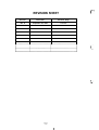
REVISION SHEET
Revision
Issue Date
Revision Page
Rev. A
September 28, 1994
1st issue
.-..>
.$...
.,,
.
-v1
TABLE OF CONTENTS
CHAPTER 1.
PRODUCT DESCRIPTION
CHAPTER 2.
OPERATING PRINCIPLES
CHAPTER 3.
DISASSEMBLY AND ASSEMBLY
CHAPTER 4.
ADJUSTMENTS
TROUBLESHOOTING
MAINTENANCE
CHAPTER 5.
CHAPTER 6.
APPENDIX
- vi -
..
CHAPTER
1
Product Description
Table of Contents
1.1 FEATURES
1-1
1.2 SPECIFICATIONS
1-2
1-2
1.2.1.1 Paper Handling Specifications . . . . . . . . . . . . . . . . . . . . . . . . . . 1-3
1.2.1.2 Paper Specifications. . . . . . . . . . . . . . . . . . . . . . . . . . . . . . . . . . 1-4
1.2.1.3 Printable Area... . . . . . . . . . . . . . . . . . . . . . . . . . . . . . . . . . . . . 1-5
1.2.1.4 Ribbon Specifications . . . . . . . . . . . . . . . . . . . . . . . . . . . . . . . . . 1-7
1.2.1.5 Electrical Specifications . . . . . . . . . . . . . . . . . . . . . . . . . . . . . . . 1-7
1.2.1.6 Environmental Conditions. . . . . . . . . . . . . . . . . . . . . . . . . . . . . . 1-7
1.2.1.7 Reliability. . . . . . . . . . . . . . . . . . . . . . . . . . . . . . . . . . . . . . . . . . . 1-7
1.2.1.8 Safety Approvals. . . . . . . . . . . . . . . . . . . . . . . . . . . . . . . . . . . . . 1-8
1.2.1.9 Physical Specifications . . . . . . . . . . . . . . . . . . . . . . . . . . . . . . . . 1-8
1.2.2 FirmwareS pacifications. . . . . . . . . . . . . . . . . . . . . . . . . . . . . . . . . . . . . . 1-8
1.2.1 Hardware Specifications . . . . . . . . . . . . . . . . . . . . . . . . . . . . . . . . . . . . .
1-11
1.3 INTERFACE SPECIFICATIONS
1.3.1 Paraliellnterface. . . . . . . . . . . . . . . . . . . . . . . . . . . . . . . . . . . . . . . . . . 1-11
1.3.1.I Compatible Mode . . . . . . . . . . . . . . . . . . . . . . . . . . . . . . . . . . . 1-11
1.3.1.2 Reverse Mode. . . . . . . . . . . . . . . . . . . . . . . . . . . . . . . . . . . . . . I-13
1.3.2 Serial Interface . . . . . . . . . . . . . . . . . . . . . . . . . . . . . . . . . . . . . . . . . . . 1-14
1.3.3 Interface Selection . . . . . . . . . . . . . . . . . . . . . . . . . . . . . . . . . . . . . . . . . 1-15
1.3.4 Preventing the Host from Data TransferTimeout . . . . . . . . . . . . . . . . . 1-15
1.4 OPERATING INSTRUCTIONS
1.4.1 Control Panel Operation . . . . . . . . . . . . . . . . . . . . . . . . . . . . . . . . . . . .
1.4.2 Self-test Function. . . . . . . . . . . . . . . . . . . . . . . . . . . . . . . . . . . . . . . . . .
1.4.3 Hexadecimal Dump Function . . . . . . . . . . . . . . . . . . . . . . . . . . . . . . . . .
1.4.4 Micro Adjustment Function . . . . . . . . . . . . . . . . . . . . . . . . . . . . . . . . . .
1.4.5 PrinterStatus Indication.. . . . . . . . . . . . . . . . . . . . . . . . . . . . . . . . . . . .
1.4.6 Selected Font . . . . . . . . . . . . . . . . . . . . . . . . . . . . . . . . . . . . . . . . . . . .
1.4.7 Printer Initialization . . . . . . . . . . . . . . . . . . . . . . . . . . . . . . . . . . . . . . . .
1.4.7.1 Power-on Initialization. . . . . . . . . . . . . . . . . . . . . . . . . . . . . . . .
1.4.7.2 Hardware Initialization. . . . . . . . . . . . . . . . . . . . . . . . . . . . . . . .
1.4.7.3 Software Initialization . . . . . . . . . . . . . . . . . . . . . . . . . . . . . . . .
1.4.8 PrinterSettings . . . . . . . . . . . . . . . . . . . . . . . .......:. . : . . . . . . . . .
1.4.8.1 Selectable PrinterSettings . . . . . . . . . . . . . . . . . . . . . . . . . . . .
1.4.8.2 Changing the Default Settings. . . . . . . . . . . . . . . . . . . . . . . . . .
1-16
1-16
1-17
1-17
1-18
1-18
1-19
1-19
1-19
1-19
1-19
1-20
1-20
1-20
1-24
1.5 MAIN COMPONENTS
1.5.1 C143 MAIN Board . . . . . . . . . . . . . . . . . . . . . . . . . . . . . . . . . . . . . . . . . 1-24
1.5.2 C130PSB/PSE Board. . . . . . . . . . . . . . . . . . . . . . . . . . . . . . . . . . . . . . 1-24
1.5.3 Printer Mechanism (M-5M1O) . . . . . . . . . . . . . . . . . . . . . . . . . . . . . . . . 1-25
1.5.4 Housing Assembly . . . . . . . . . . . . . . . . . . . . . . . . . . . . . . . . . . . . . . . . . 1-25
List of Figures
Figure 1-1. Exterior View of the LQ-300. . . . . . . . . . . . . . . . . . . . . . . . . . . . . . . 1-1
Figure l-2. Pin Configuration . . . . . . . . . . . . . . . . . . . . . . . . . . . . . . . . . . . . . . . 1-2
Figure l-3. PrintableAreafor Cut Sheets . . . . . . . . . . . . . . . . . . . . . . . . . . . . . 1-5
Figure l-4. PrintableAreafor Envelopes . . . . . . . . . . . . . . . . . . . . . . . . . . . . . . 1-6
Figure l-5. PrintableAreafor Continuous Paper . . . . . . . . . . . . . . . . . . . . . . . . 1-6
Figure l-6. Data Transmission Timing . . . . . . . . . . . . . . . . . . . . . . . . . . . . . . . 1-11
Figure 1-7. Control Panel. . . . . . . . . . . . . . . . . . . . . . . . . . . . . . . . . . . . . . . . . 1-16
Figure l-8. C143 MAIN Board Component Layout . . . . . . . . . . . . . . . . . . . . . . I-24
Figure l-9. C130 PSB/PSE Board Component Layout . . . . . . . . . . . . . . . . . . 1-24
Figure 1-10. Printer Mechanism (M-5 M1O). . . . . . . . . . . . . . . . . . . . . . . . . . . . 1-25
Figure 1-11. Housing Assembly. . . . . . . . . . . . . . . . . . . . . . . . . . . . . . . . . . . . 1-25
!!,’:~\.,
List of Tables
Table l-1. Optional Units . . . . . . . . . . . . . . . . . . . . . . . . . . . . . . . . . . . . . . . . . . 1-1
Table l-2. PaperThickness LeverSettings . . . . . . . . . . . . . . . . . . . . . . . . . . . . 1-3 (:;
Table l-3. Feeding Speed . . . . . . . . . . . . . . . . . . . . . . . . . . . . . . . . . . . . . . . . . 1-4
Table 1-4. Specifications for Cut Sheet Paper (CSF). . . . . . . . . . . . . . . . . . . . . 1-4
Table 1-5. Specifications for Cut Sheet Paper (Manual Insertion) . . . . . . . . . . . 1-4
Table -6. Specifications forEnvelopes . . . . . . . . . . . . . . . . . . . . . . . . . . . . . . . 1-4
Table -7. Specifications for Continuous Paper (Single Sheet and Multi-Part) . 1-4
Table -8. Specifications for Continuous Paper with a Label. . . . . . . . . . . . . . . 1-5
Table -9. Electrical Ranges . . . . . . . . . . . . . . . . . . . . . . . . . . . . . . . . . . . . . . . 1-7
Table -lO. CharacterTables. . . . . . . . . . . . . . . . . . . . . . . . . . . . . . . . . . . . . . . 1-8
Table -11. Resolution. . . . . . . . . . . . . . . . . . . . . . . . . . . . . . . . . . . . . . . . . . . . 1-9
Table -12. Printing Speed. . . . . . . . . . . . . . . . . . . . . . . . . . . . . . . . . . . . . . . . 1-10
Table -13. Signal and Connector Pin Assignments forthe Parallel Interface. 1-12
Table -14. Signal and ConnectorPin Assignments forthe Parallel Interface. 1-13
Table -15. Signal and Connector Pin Assignments forthe Serial Interface . . 1-14
Table -16. Paper Feeding Functions . . . . . . . . . . . . . . . . . . . . . . . . . . . . . . . 1-17
Table -17. Font Selection. . . . . . . . . . . . . . . . . . . . . . . . . . . . . . . . . . . . . . . . 1-19
Table -18. Font Lightsand Language Selection . . . . . . . . . . . . . . . . . . . . . . . 1-20
f“~.
Table -19. Default Options . . . . . . . . . . . . . . . . . . . . . . . . . . . . . . . . . . . . . . . 1-21
..
Table -20. CharacterTables. . . . . . . . . . . . . . . . . . . . . . . . . . . . . . . . . . . . . . 1-21
Table -21. Page Length . . . . . . . . . . . . . . . . . . . . . . . . . . . . . . . . . . . . . . . . . 1-22
Table -22. SkiDOver Perforation/Auto TearOff/AGM/Auto Line Feed
EX~/ACK/ State Reply . . . . . . . . . . . . . . . . . . . . . . . . . . . . . . . . . 1-22
Table l-23. Graphic Ptint Direction . . . . . . . . . . . . . . . . . . . . . . . . . . . . . . . . . 1-22
Table l-24. Software . . . . . . . . . . . . . . . . . . . . . . . . . . . . . . . . . . . . . . . . . . . . 1-22
Tablel-25.interface . . . . . . . . . . . . . . . . . . . . . . . . . . . . . . . . . . . . . . . . . . . . 1-22
Table l-26. Bit Rate. . . . . . . . . . . . . . . . . . . . . . . . . . . . . . . . . . . . . . . . . . . . . 1-22
Table 1-27. Parity Bit . . . . . . . . . . . . . . . . . . . . . . . . . . . . . . . . . . . . . . . . . . . . 1-23
Table 1-28. Data Length. . . . . . . . . . . . . . . . . . . . . . . . . . . . . . . . . . . . . . . . . . 1-23
Product Description
LWOO Service Manual
1.1 FEATURES
The LQ300 is a small, light-weight, 24pin serial impact dot-matrix color printer suitable for
personal use. The major features of this printer are:
Fast printing of lo-cpi draft characters at 200 cps
Compact design saves precious work space
●
Easy-to-operate panel
● Quiet
printing
●
Two built-in 8-bit parallel interfaces and an EIA-232D serial interface
●
Printing of up to 66 kes on A4-size or 62 lines on letter-size paper
●
Optional color printing using a color ribbon (black, magenta, cyan, yellow)
●
Detachable tractor (push, pull, and push-pull tractor feed)
●
●
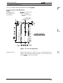
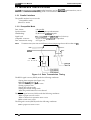
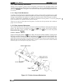
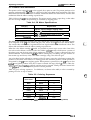
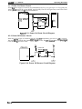
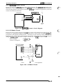
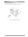
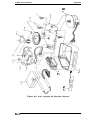
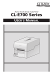
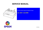
Figure 1-1 shows an exterior view of the LQ-300, and Table 1-1 lists the optional units available for
the LQ-300.
~’”pe’”Q@’
lease
r
Knob
Power s
Sprocket
lever
Center support
Tractor unit
Figure 1-1. Exterior View of the LQ-300
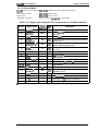
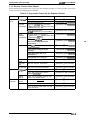
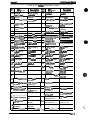
Table 1-1. Optional Units
Description
Model
#77!53
Ribbon oartridge (monochrome)
#7755
Ribbon oartridge (monochrome, sub-cartridge)
#7768
Ribbon cartridge (film)
S015077
Ribbon oartridge (color)
C80637*
Single-bin cut sheet feeder
C83211•
Color upgrade kit
C80030*
Pull tractor unit
* The number represented by an asterisk varies depending on the country.
Rev. A
“l-1
Product Description
LQ-300 Service Manual
1.2 SPECIFICATIONS
This
r
section provides detailed information about the LQ-300.
.T,
,$
,’
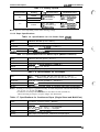
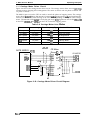
1.2.1 Hardware Specifications
Printing method:
5erial impact dot matrix
Pin arrangement:
12 x 2, staggered
0.20 mm (0.0079 inches)
Pin diameter:
.
o
m
.
E
E
In
4
m
II
m
a
x
L“?”’”
3f,
!
5 ()
!
7
()
I
9 ()
i
1 1 ()
-!
?
‘o
()
()
6
()
8
{:
. , .-
() 10
1 3 ()
HEAD CENTER
15 ()
‘o
17< )
7
1 9 ()
a
.
\
{\
21 ( )
2 2 ()
() 1 6
I
ij;;:
i()22
I
f5
L’ 2 4
Figure 1-2. Pin Configuration
Printing direction:
1-2
Bidirectional with logic seeking for text and unidirectional for
graphics. (Bidirectional printing of graphics can be selected with a
printer setdng or software command.)
Rev. A
p
.....
LWOO Service Manual
Product Description
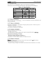
1.2.1.1 Paper Handling Specifications
Paper paths
Cut sheet path:
Continuous paper paths:
Continuous paper parking:
CSF:
Feeding pitch:
Feeding system:
Rear entry (manual insertion or optional CSF)
Cannot handle multi-part paper using friction feed
Rear entry ( push tractor feed using the push tractor unit
or pull tractor feed using the pull tractor unit or push-pull
tractor feed using both tractor units)
Possible, using push tractor unit
Cannot handle envelopes or multi-part paper
% ~~, 1A ~ch, or Programmable feeding in increments of
$%o inch, minimum
Friction feed or &actor (push, pull, and push-pull) feed
❑ Friction feed
Set the release lever to the friction position.
. Insert the left edge of the sheet at the marked position.
●
Do not.perform reverse feed in the area within 0.63 inch (16 mm) from the bottom edge of
the sheet.
●
Push tractorfeed
Set the release lever to the tractor position.
Install the tractor unit in the rear in the push &actor position.
●
On the first page (that is, the page immediately after sheet loading) the accuracy of paper
feeding is not guaranteed within the area 0.87 inch (22 mm) from the top edge of the sheet.
●
On the last page, the accuracy of paper feeding is not guaranteed after the paper comes off
the tractor pins.
● During printing oflabels, never perform reverse feeding.
● Do not eject the labels from the rear.
●
●
❑ Pull tractor feed
Set the release lever to the tractor position.
. Install the tractor unit in the top in the pull tractor position.
● Do not perform reverse feeding.
● Do not eject them from the rear.
●
Push pull tractor feed
Set the release lever to the tractor position.
Install one tractor unit in the rear in the push tractor position and install the other tractor unit
in the top in the pull tractor position.
. Do not perform reverse feeding.
● Do not eject the paper from the rear.
●
●
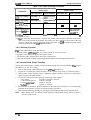
Paper thickness leve~
The adjust lever must be set to proper position for the
paper thickness, as shown below.
Table 1-2. Paper Thickness Lever Settings
Paper Thickness
Lever Position
o
0.065 mm -0.12 mm (0.0026 in. -0.0047 in.)
Ordinary paper
1
0.12 mm -0.19 mm (0.0047 in. -0.0075 in.)
Multi-part forms (2 sheets)
2
0.19 mm -0.26 mm (0.0075 h. -0.01 in.)
Multi-part forms (3 sheets)
3
0.26 mm -0.32 mm (0.01 in. -0.013 in.)
Multi-part forms (4 sheets)
4
0.32 mm -0.44 mm (0.013 in. -0.017 in.)
Envelopes (20 lb.)
5
0.44 mm -0.52 mm (0.017 in. -0.02 in.)
Envelopes (24 lb.)
Paper-feeding speed:
Rev. A
Corresponding Paper
See Table 1-3.
1-3
Product Description
LQ-300 Service Manual
Table 1-3. Feeding Speed
Lever Position
Feeding
1/6 inch Line Feed
Friction
o, 1
Friction
2-5
Tractor
Max 3.6 incheslsec.
Typ. 3.3 incheshec (*)
Min. 2.8 inchhec.
Max. 94 ins/line
Typ. 80 ins/line (*)
Min. 75 ins/line
Tractor
I
Continuous Feed
I
I
Max. 106 redline
Typ. 104 ins/line (*)
Min 94 m.s/line
Max. 2.8 incheslsec.
Typ. 2.5 inche.shec.’
Min. 2.2 incheskec.
* Feed speed is varies depending on the motor driving voltage.
1.2.1.2 Paper Specifications
Table 1-4. Specifications for Cut Sheet Paper (CSF)
Width
182 mm -216 mm (7.2 in. -8.5 in.)
Length
210 mm -364 mm (8.3 in. -14.3 in.)
Thickness
10.07 mm -0.12 mm (0.0028 in. -0.0047 in.)
Weight
64-90 g/m2 (18 -24 lb.)
Qualitv
Plain oaDer. recvcled DaDer
I
Table 1-5. Specifications for Cut Sheet Paper (Manual Insertion)
Width
148 mm -257 mm (5.8 in. -10.1 in.)
Length
182 mm -364 mm (7.2 in. -14.3 in.)
Thickness
0.065 mm -0.14 mm (0.0025 in. -0.0055 in.)
Weight
52.3-90 g/m2 (14 -24 lb.)
I Plain paper, recycled paper
Quality
Table 1-6. Specifications for Envelopes
Size
No.
Thickness
0.16 mm - 0.52 mm (0.0063 in. - 0.0197 in.)
Weight
45- 91 g/m2 (12 -24 lb.)
Quality
Bond paper (not curled, folded, or crumpled), plain paper, airmail paper
6
No. 10
Width x Length: 166 mm x 92 mm (6.5 in. x 3.6 in.)
Width x Length: 240 mm x 104 mm (9.5 in. x 4.1 in.)
Notes: . Printing of envelopes is guaranteed only at room temperature and normal humidity (15
- 25° C (59 - 77° F) ,20- 60% RI-I).
● Variations in envelope thickness must be less than 0.25 mm (0.0098 in.).
. When inserting envelopes, keep the longer side horizontal.
Table 1-7. Specifications for Continuous Paper (Single Sheet and Multi-Part)
Width
101.6 mm - 254 mm (4.0 in. - 10.0 in.)
Total thickness
0.065 mm - 0.32 mm (0.0025 in. - 0.012 in.)
Weights
52.3- 82 g/m2 (14 - 22 lb.) — not multi-part
40- 58.2 g/m2 (12 - 15 lb.) — multi-part
Copies
4 sheets (1 original + 3 copies)
Quality
Plain paper, recycled paper, carbonless multi-part paper
1-4
Rev. A
Product Description
LQ-300 Service Manual
Table 1-8. Specifications for Continuous Paper with a Label
Label size (W x L)
63.5 mm (min.) x 23.8 mm (min.) [ 2.5 in. (min.) x 15/16 in. (min.)]
Width of base paper
101.6 mm -254 mm (4.0 in. x 10,0 in.)
Thickness of base
paper
0.07 mm - 0.09 mm (0.0028 in. - 0.0031 in.)
Total thickness
0.16 mm -0.19 mm (0.0063 in. - 0.0075 in.)
Weight
68 g/m2 (17 lb.)
Quality
Plain paper
Notes:
● Use only continuous-type labels and use them only with the tractor.
. Examples of labels —Avery Continuous Form Labels
—Avery Mini-Line Labels
● Printing of envelopes is guaranteed only at room temperature and normal humidity (15
- 25° C (59 - ’77° F) ,20- 6(Mo RI+).
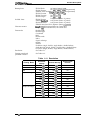
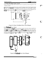
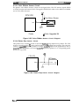
1.2.1.3 Printable Area
Cut sheets
3mm[0.12”]
minimum
D
G-
3mm[0.12”]
minimum
b
—
—
—
—
4
5,3mm[0.2”]
minimum
. :.,
Printable area
4
9mm[0.35”]
minimum
—
—
Figure 1-3. Printable Area for Cut Sheets
Rev. A
1-5
LQ-300 Service Manual
Product Description
Envelopes
3mm[0.12”]
minimum
3mm[0.12”]
minimum
k,
=,
AL
5.3mm[0.21”]
minimum
Printable area
T
13.5mm[0.53*]
minimum
Figure 1-4. Printable Area for Envelopes
Continuous paper
13 mm
minimum
10.51 m ], ~ :
4----++
203.2 mm [8”], maximum
0,
0,
06
0,
0,
0,
0,
0,
0,
0,
0,
0,
0,
0,
0,
.o---0,
0,
0,
0,
0. ., . - . . . . . . . - . . . . - .
0,
0,
0,
0,
Q-r-0,
0,
0,
0,
0,
0,
0,
0,
0,
0,
04
0,
0,
0,
:0
,0
,0
,0
,0
,0
,0
,0
,0
,0
,0
,0
,0
,0
,0
,0
,0
,0
,0
,0
,0
:6
,0
,0
,0
,0
,0
,0
,0
,0
,0
,0
,0
,0
,0
,0
,0
,0
,0
,0
Figure 1-5. Printable Area for Continuous Paper
1-6
Rev. A
LQ-300 Service Manual
Product Description
1.2.1.4 Ribbon Specifications
Ribbon cartridge (mono):
Ribbon cartridge (film):
Ribbon cartridge (color):
#7753
#7755 (sub-cartridge)
#7768
S015077
Ribbon color:
Black, magenta, cyan, yellow
Black ribbon life:
Film ribbon life:
Color ribbon life
Black:
Magenta:
cyan:
Yellow:
2 million characters (48 dots/character)
0.2 million characters (48 dots/character)
1 million characters (48 dots/character)
0.7 million characters (48 dots/character)
0.7 million characters (48 dots/character)
0.5 million characters (48 dots/character)
1.2.1.5 Electrical Specifications
Table 1-9. Electrical Ranges
Description
120 V Version
230 V Version
120 VAC
220-240 VAC
103.5-132 VAC
198-264 VAC
Rated voltage
Input voltage range
Rated frequency range I
Input frequency range
Rated current
Dielectric strength
50- 60 t-fz
49.5- 60.5 Hz
1
I
I
1.1 A
I
0.6 A
1000 VAC ms for 1 minute or
1500 VAC rms for 1 minute
1200 VAC rms for 1 second
(between AC line and chassis)
(between AC line and chassis)
1.2.1.6 Environmental Conditions
Temperature range:
Operation:
5to35“C (41 to 95 “F)
Operation (film ribbon): 15to35‘C (59 to 95 ‘F)
Operation (envelopes,
labels, or recycled paper): 15to25‘C (59 to 77°F)
Storage:
–20 to55‘C (-4 to 131 ‘F)
Humidity (without condensation):
Operation:
5 to
Operation (film ribbon):
10 to 80Y0 RH
80?40 RH
Operation (envelopes,
labels, or recycled paper): 20 to 60Y0 RH
Storage:
5 to
W’/. RH
1.2.1.7 Reliability
MTBF:
Printhead life:
Rev. A
4000
power on hours (POH)
200 million strokes/wire (with monochrome ribbon)
100 million strokes/wire (with color and film ribbon)
1-7
Product Description
LQ-300 Service Manual
1.2.1.8 Safety Approvals
Safety standards:
UL1950 with D3, CSA22.2 #950 with D3
U.S. version:
European version: EN 60950 ~)
IEC950 (SEMKO, DEMKO, NEMKO, SETI)
Radio frequency interference: U.S. version:
FCC part 15 subpart B class B
(RFI)
European version:
Vfg.243 (VDE0878 part 3, pati 30)
EN55022 (CISPR PUB. 22) class B
1.2.1.9 Physical Specifications
Dimensions (W x D x H):
366 x 275x 141 mm (14.4 x 10.8x 5.6 inches) without tractor
Weight without tractoc
4.3 kg (9.5 lb.)
1.2.2 Firmware Specifications
Control codes:
Input data buffer
ESC/P2
IBM X24E emulation
EPSON remote
8KB
Download memory:
10KB
Character sets:
Character tables:
14 international character sets and one legal character set
Table 1-10. Character Tables
Character Table
Standard Model
NLSP* Model
0
0
PC850 (Multilingual)
o
o
o
PC860 (Portuguese)
o
x
PC861 (Icelandic)
o
x
PC863 (Canadian-French)
o
x
PC865 (Norwegian)
o
x
ITALIC
PC437 (US, Standard Europe)
BRASCII
0
Iolxl
Abicomp
o
x
PC852 (East Europe)
x
o
PC853 (Turkish)
x
o
PC855 (Cvrillic)
x
o
PC857 (Turkish)
Ixlol
PC864 (Arabic)
Ixlol
PC866 (Russian)
x
o
PC869 (Greek)
x
o
PC437 Greek
x
o
ISO Latin IT (TuAish)
x
o
ISO 8859-7 (Greek)
x
o
Code MJK (Czecho, Slovakia)
x
o
MAZOWIA (Polland)
x
o
Bulgaria (Bulgaria)
x
o
x Not suppofled
0 Suppotied
‘ NSLP = National Language Suppori
1-8
Rev. A
,ffq
L-. .,
Product Description
LC?-300 Service Manual
Bitmap fonts:
Scalable fonts:
Character matrix:
Print mode:
Resolution:
Printing speed and
printable columns:
(10 cpi/ 12 cpi/ 15 cpi)
EPSON Draft
(10 cpi/ 12 cpi/ 15 cpi/ Proportional)
EPSON Roman
EPSON Saris Serif (lOcpi/ 12cpi/ 15cpi/ Proportional)
(10 cpi/ 12 cpi/ 15 cpi)
EPSON Courier
(10 cpi/ 12 cpi)
EPSON Prestige
(10 cpi/ 12 cpi)
EPSON Script
8-32 points (units= 2 points)
EPSON Roman
8-32 points (units= 2 points)
EPSON !%ns serif
8-32 points (units= 2 points)
EPSON Roman T
EPSON Saris Serif H 8- 32points (units =2points)
Drailt 10 cpi; 12 horizontal dots, 24 vertical dots
NLQ 10 cpi; 36 horizontal dots, 24 vertical dots
Double-width
Double-height
Condensed
Bold
Double-strike
Italics
Super/subscript
Outline
Shadow
Underline (single, double, single-broken, double-broken)
Strike-through (single, double, single-broken, double-broken)
OverScore (single, double, single-broken, double-broken)
See Table 1-11.
See Table 1-12.
Table 1-11. Resolution
Printing Mode
Density
Vertical Density
Adjacent Dot
Printed?
Draft
120 dpi
180 dpi
No
Draft condensed
240 dpi
180 dpi
No
LQ
360 dpi
180 dpi
No
60 dpi
60 dpi
Yes
120 dpi
60 dpi
Yes
120 dpi
60 dpi
No
240 dpi
60 dpi
No
80 dpi
60 dpi
Yes
90 dpi
60 dpi
Yes
60 dpi
180 dpi
Yes
120 dpi
180 dpi
Yes
90 dpi
180 dpi
Yes
180 dpi
180 dpi
Yes
360 dpi
180 dpi
No
8-pin bit image
24-pin bit image
Rev. A
Horizontal
1-9
LWOO Service Manual
Product Description
Table 1-12. Printing Speed
Printing Mode
Draft
Draft condensed
LQ condensed
Vote:
Chg\;gter
Printable
Columns
F“.}
Maximum Print Speed [cps]
Mode 1
Mode 2
Mode 3
10 cpi
80
200
133
100
12 cpi
96
240
160
120
15 cpi
120
300
200
150
17 cpi
137
171
114
86
20 cpi
160
200
133
100
10 cpi
80
67
50
33
12 cpi
96
80
60
40
15 cpi
120
100
75
50
17 cpi
137
114
86
57
20
160
133
100
67
Each maximum print speed is changeable depending on attributes of characters within
T >12 “C
Th c 0.19 m m
{ T <12 “C
Printing Mode
--c
—
Mode 1
V: Down
—
Mode 3
V:
—
Mode 2
V:
Normal
Normal
+_ V: Down— Mode 3
J
~Th>01,mm{T212 .+;:;:;:
-.
T <12 “C
{“
V: Down— Mode 3
Th: Paper thickness
T : Printhead temperature
V : Printhead driving voltage
,,
1-1o
Rev. A
Product Description
LQ-300 Service Manual
1.3 INTERFACE SPECIFICATIONS
LQ-300 has a Centronics<ompatible parallel interface and an EIA-232D serial interface, one of
which can be selected in default setting mode. Auto selection is also available.
1.3.1 Parallel Interface
The parallel interface has two modes:
. Compatible mode
● Reverse mode
1.3.1.1 Compatible Mode
Handshaking:
Signal level:
Adaptable comector:
Data transmission timing:
Note:
.
8-bit parallel
By STROBE pulse synchronization
By BUSY and ACKNLG signals
Data format:
Synchronization:
Tl_’L-compatible level (IEEE-P1284 level 1 device)
36-pin 57-30360 (Amphenol) or equivalent
See Figure 1-6.
Transition time (rise time and fall time) of every input signal must be less than 0.2 ps.
BUSY
ACKNLG
DATA
S T R O B E
—
~
.
Figure 1-6. Data Transmission Timing
The BUSY signal is active (HIGH) under the following conditions:
. During data reception (See Figure 1-6.)
When the innt buffer is full
. When the INIT input signal is active
. During a printer error
. During the self-test mode
. During the default setting mode
. When the parallel interface is not selected
●
The ERROR signal is active (LOW) under the following conditions:
. When a paper-out error occurs
. When a release lever operation error occurs
● When a fatal error occurs
The PE signal is active (HIGH) under the following conditions:
●
When a
Rev. A
paper-out error occurs
1-11
Product Description
LQ-300 Service Manual
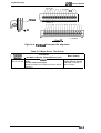
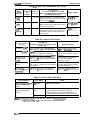
Table 1-13 shows the connector pin assignments and signal functions for the 8-bit parallel interface.
Table 1-13. Signal and Connector Pin Assignments for Parallel Interface
Pin No.
Signal Name
(!!%”%
1
19
In
20-27
In
28
out
DATAO-DATA7
2-9
ACKNLG
10
11
BUSY
12
‘
13
SLCT
14
AFXT
E
29
28
28
Description
‘0’
STROBE
out
out
out
The STROBE pulse is used to read the input
data. The pulse width must be more than 0.5 ps.
Input data is latched after the falling edge of this
signal.
Parallel input data to the printer.
A HIGH level means data 1.
A LOW level means data O.
This pulse indicates data has been received and
the printer is ready to accept more data. The
pulse width is approximately 12 U.S.
HIGH indicates the printer cannot acoept more
data.
HIGH indicates paper-out. This signal is effective
only when the ERROR signal is LOW.
Always HIGH output. (Pulled up to +5 V through
3.3K Q resistor.)
Not used.
NC
30
.
In
—
16
GND
—
—
Signal ground.
17
Chassis GND
—
Chassis ground.
18
LOGIC-H
—
—
Pulled up to +5 V through 3.9K Q resistor.
19-30
GND
.
out
—
31
INIT
32
ERROR
29
33
GND
—
—
Input for printer initialization. Pulse width 50 w
minimum, active LOW.
LOW indicates that some error has o=urred in
the printer.
Signal ground.
35
+5V
—
out
Pulled up to +5 V through 3.3K Q resistor.
36
SLIN
30
In
15,34
*
30
In
out
c.%
{,,’”.
Not connected.
Signal ground.
Not used.
-c.-
7%e //0 column indicates the direction of the signal as viewed from the printer.
‘{‘
. . .
1-12
Rev. A
Product Description
LQ-300 Service Manual
1.3.1.2 Reverse Mode
LQ-300 reverse mode supports IEEE-P1284 nibble mode, described in this section.
Transmission mode:
IEEE-P1284 nibble mode
Signal level:
Adaptable connector:
IEEE-P1284 level 1 device
36-pin 57-30360 (Arnphenol) or equivalent
Table 1-14. Signal and Connector Pin Assignments for Parallel Interface
Pin No.
C%%”%
‘0’
Description
1
HostClk
19
In
Host clock signal.
2-9
DATAO-7
20-27
In
Signals DATAO through DATA7 represent data
bits O to 7.
10
Ptrclk
28
out
Printer clook signaL
11
PtrBusy /
DataBit-3,7
29
out
Printer busy signal and reverse channel transfer
data bit 3 or 7.
12
AckDataReq /
DataBit-2,6
28
out
Acknowledge data request signal and reverse
channel transfer data bit 2 or 6.
out
X-flag signal and reverse channel transfer data
bit 1 or5.
In
—
Host busy signal.
Not oonnected.
13
*
Signal Name
Xflag I
DataBit-l,5
28
14
HostBusy
15
NC
30
—
16
GND
.
—
Signal ground.
17
Chassis GND
—
Chassis ground.
18
Logic-H
—
—
Pulled up to +5 V via 3.9K Q resistor.
19-30
GND
—
out
—
31
m
30
In
32
DataAvail /
DataBit-0,4
29
33
GND
34
Signal ground.
Not used.
out
Data available signal and reverse channel
transfer bit O or 4.
—
—
Signal ground.
NC
—
—
Not oonnected.
35
+5 v
—
out
Pulled up to +5 V via 3.3K S2 resistor.
36
1284-Active
30
In
1284 active signal.
The l/O column indicates the direction of the signal as viewed from the printer.
Rev. A
1-13
LQ-300 Service Manual
Product Description
1.3.2 Serial Interface
The LQ-300 is equipped with an 8-bit serial interface, standard.
Data format:
Synchronization:
EIA-232D serial
Asynchronous
Handshaking:
By DTR protocol, X-ON/X-OFF protocol, ETX/ACK protocol
Word length
Start bits:
Data bits:
Parity bit:
Stop bits:
1 bit
7 or 8 bits (selectable)
Odd, even, or none (selectable)
1 bit
Bit rate:
Logic level
MARK ~OgiCid 1):
SPACE (logical O):
Parity check:
Connectoc
300,600,1200,2400,4800, 9600,19200 bps (selectable)
–3 V to –25 V
+3 v to +25 v
Odd, even, or no parity bit (selectable)
EIA standard 25-pin D-SUB female comector
Table 1-15. Signal and Connector Pin Assignments for Serial Interface
Pin No.
Signal Name
I/o’
1
Chassis GND
—
Chassis ground.
2
TXD
out
Transmit serial data.
3
RXD
In
Receive serial data.
4
RTS
out
7
Signal GND
—
Request to send. Always SPACE level when the printer
is powered on. Pulled up to +12V via 4.7K Q wsistor.
Return path for data and control signals.
11
REV
out
Conneoted directly to the DTR signal.
20
DTR
out
Indicates that the printer is ready to receive data or not.
5,6,8-10,
12-19,
21-25
NC
—
No connection (not used).
*
* . .
.
\>, ~
Description
l%e //0 column indicates the direction of the signal as viewed from the printer.
,-,...
1-14
Rev. A
LQ-300 Service Manual
Product Description
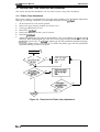
1.3.3 Interface Selection
The printer has 2 interfaces: parallel and serial. These interfaces can be selected manually in
default-setting mode or selected automatically.
●
Manual selection
One of the two interfaces can be selected in default-setting mode.
. Automatic selection
When automatic interface selection is enabled in default-setting mode, the printer is
initialized to idle state scanning, in which an interface receives data when it is powered
on, and the interface that receives data first is selected. When the host stops data transfer,
and the printer is in the standby state for 10 or 30 seconds (time selectable in the
default-setting mode), the printer returns to the idle state. As long as the host sends data
to the printer interface in the BUSY state, the currently selected interface remains the
same.
. Interface state and interface selection
When the parallel interface is not selected, the interface is in the BUSY state. When the
serial interface is not selected, the interface sends X-OFF and sets the DTR signal MARK.
When the printer is initialized or returned to the idle state, the parallel interface is in a
READY state, the serial interface sends X-ON and sets the DTR signal SPACE. Notice
that the interrupt signal such as a INIT signal on the parallel interface is not effective
while that interface is not selected.
1.3.4 Preventing the Host from Data Transfer Timeout
Hosts abandon attempts at data transfers to peripherals when a peripheral is in BUSY state for
dozens of seconds continuously. To prevent hosts from this ldnd of timeout, the printer receives
data very slowly, several bytes per minute, even if the printer is in BUSY state. This slowdown is
started when the rest of the input buffer becomes several hundreds of bytes. Finally, when the
input buffer is full, the printer goes into the BUSY state continuously.
Rev. A
1-15
Product Description
LQ-300 Service Manual
1.4 OPERATING INSTRUCTIONS
This section describes control panel operation functions, self-test, hexadecimal dump, paper feed,
micro adjustment, and printer initialization methods.
1.4.1 Control Panel Operation
The printer control panel contains three non-lock-type push buttons and three LED indicators for
easy operation of the various printer functions.
I.ight
Buttons
Lights
A
Py:li!: :
Roman O 0
S a r i s Seriio
●
Courier*
O
Draft
Draft O W
Condensad ●
//
●
I
2
Pause
& /FF
Font
~1’[1
1’$!!d
Paper Parkd
I W ~ Micro Adjust
h
3sec
Figure 1-7. Control Panel
Buttons
Pause:
Font:
LFIFF:
Switches printer status between printing and no printing, if there is
print data in the input buffer. When the printer is out of paper, the
light flashes and the beeper sounds three times.
S&c& one of the available fonts. When you hold down this button
while you turn on the printer, you enter the printer setting mode.
When you press this button, the printer feeds paper line by line.
Hold it down to load a single sheet, or to advance continuous paper
to next top-of-form position.
Indicators
Pause (Orange):
Font 1 and 2 (Green):
Lights when the printer in pause mode.
Indicates the currently selected font.
Special Mode
Self-test mode:
Hex dump mode:
Hold down the LF/FF button and turn on the printer.
Hold down the LF/FF and Font buttons and turn on the printer.
Default-setting mode:
Hold down the Font buttons and turn on the printer.
Micro adjustment mode:
Hold down the Pause button or Font button.
Paper park mode:
Hold down the Font and LF/FF buttons together.
1-16
Rev. A
Product Description
LC?-300 Service Manual
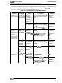
Table 1-16. Paper Feeding Functions
Not Paper Out
Press LF/FF and
Font buttons at the
same time
Insert a sheet to the
manual insetiion slot
Paper Out State
Paper park (*1)
—
I
Friction Feed
Tractor Feed
Operations
Not Paper Out
Paper Out State
Line feed
Load a sheet (*2)
Eject
Load a sheet (*2)
—
—
—
—
—
After 2 seconds
load the sheet
manuallv (*2)
(*l):~@n the printer is in tear-off state, the.w functions a~ performed after returning from the
tear-off position.
(*2) Gce a manually inserted sheet is loaded, the printer enters manual insertion mode. After
that, even if data remains in the buffer, the printer goes into a paper out error state at the end
of every a sheet and waits for insertion of the next sheet. The CSF is enabled again by sheet
loading operation from the CSF or by initialization.
1.4.2 Self-test Function
W section explains how to run the self-test.
1. Hold down the LF/FFbutton and turn on the printer to start the self-test.
2. If paper is not loaded, the printer attempts to load it.
3. The printer prints alphanumeric characters continuously.
5. Quit self-test mode printing bypressingthe Pause button and turning the printer off.
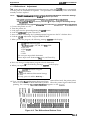
1.4.3 Hexadecimal Dump Function
The hexadecimal dump is a useful tool for troubleshooting data control problems. This section
describes how to run a hex dump.
1.
2.
3.
Turn on the printer while holding down the LF/FF and Font buttons.
If paper is not loaded, the printer attempts to load it (either single sheet or continuous paper).
If the printer cannot Ioad the paper, it indicates a paper-out error. In this case, insert paper
again, and press the Pause button.
4. The printer waits for data after printing the message “Hex dump(*).”
English or German is selected
“Hex Dump”:
French is selected
“Codes Hexadecirnaux”:
Italian is selected
“Dump esadecimale”:
“Volcado hex”:
Spanish is selected
5. Received data is printed as both hexadecimal codes and ASCII characters. If a corresponding
printable character does not exist, the printer outputs a period (.).
6. Quit hexadecimal dump printing by pressing the PAUSE button and turning the printer off.
Note:
In hex dump mode, the character table depends on the default setting, and 10 cpi draft is
selected automatically.
Rev. A
1-17
LQ-300 Service Manual
Product Description
1.4.4 Micro Adjustment Function
To enter adjustment mode, press the Pause button for three seconds, until the printer beeps once
and the Pause lights bhnk to indicate that the adjustment operation is available. If the printer state
is not one of the conditions shown below, this operation is ignored.
...
‘~
f
., . .
TOF position adjustment:
The position can be adjusted just after the paper is loaded.
● Tear-off position adjustment:
The position can be adjusted when paper is actually located at the tear-off position.
●
In the adjustment mode, press the LF/FF button to feed paper forward and the Font button to feed
paper backward. You can cancel adjustment mode by pressing the Pause button or inputting a
print coremand. The adjusted position is stored in non-volatile memory.
1.4.5 Printer Status Indication
This section describes how the printer indicates status and error conditions using LEDs and the
beeper.
The symbols below describe the frequency of beeper sounds.
(.):
The beeper sounds for 100 rns with an interval of 100 ma between beeps.
(—): The beeper sounds for500rns.
signal is active:
During initialization:
Standby or printing state:
Pause state:
Micro adjustment mode:
While initialize
Tear-off:
Paper-out error state(”l)
Operating error (~), fatal error (*3):
Pause light is on.
Pause light blinks
Pause light is off
Pause light is on
Beeper sounds ( ● ) and Pause light blinks.
(light on:off ratio= 1:1)
Pause light blinks (light on:off ratio= 1:6)
Beeper sounds (.. . ) and Pause light blinks
(light on:off ratio= 6:1)
Beeper sounds (— ) and Pause light is on.
Notes:
(*1):
A paper-out error occurs with any of the following conditions:
● Paper is not loaded after loading is attempted.
● A full sheet finishes printing after single sheet loading by manual insertion.
● The end of condrmous paper is reached.
When a paper-out error occurs, the printer stops printing and enters the pause state. After
that, when a sheet is loaded, the PAUSE light stops blinking and the light stays on, but
the printer remains in the pause state. Press the PAUSE button to start printing.
(*2):
(*3):
An operating error occurs for any of the following conditions:
● The release lever is set to the TRACTOR position without ejecting cut sheets.
● The release lever is set the FRICTION position without ejecting continuous paper.
A fatal error occurs with any of the following conditions:
● Power supply voltage is abnormal.
● Printhead temperature is abnormal.
.,
1-18
Rev. A
Product Description
LQ-300 Service Manual
1.4.6 Selected Font
The combination of two Font LEDs (1 and2) is used to indicate the selected font.
To choose one of the seven internal fonts listed on the control panel, press the Font button.
Table 1-17. Font Selection
Selected Font
\ Font 1 Light I
Font2
Light
Roman
On
On
Saris Serif
On
off
Courier
off
On
Prestiae
Blinkina
On
script
Blinking
off
Draft
On
Blinking
Draft condensed
off
off
1.4.7 Printer Initialization
There are three types of initialization:
software initialization.
power-on initialization, hardware initialization, and
1.4.7.1 Power-on Initialization
The power-on initialization is performed by turning the printer powered on. When the power-on
initialization is performed:
. The printer mechanism is initialized.
● The hardware initialization is performed.
1.4.7.2 Hardware Initialization
Hardware initialization is performed by:
. Turning on the printer.
. The falling edge of a negative pulse ora low signal on theparallel interface /INITline.
When hardware initialization is performed:
● Print data in the input buffer is cleared.
. Download character definitions are cleared.
. The printer’s settings areretumed to the defaults.
● The printer is set to the standby condition, if no fatal error occurs.
1.4.7.3 Software Initialization
Softwme initialization is performed upon receipt of the control code ESC 62. When software
initialization is performed:
● Print characters in the buffer are not cleared.
. The printer setting is changed to the default, but download character definition is not cleared.
Rev. A
1-19
Product Description
LQ-300 Service Manual
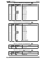
1.4.8 Printer Settings
1.4.8.1 Selectable Printer Settings
The following printer settings can be changed by users in default-setting mode:
Character table (Standard):
Character table (NLSP):
Page length:
PC437/850/860/861 /863/865 /BRASCII/Abicomp
PC437/437 Greek/850 /852/853/855/857/864/866/869 /1S0 Latin
IT /1S0 8859-7/Code MJK/Ma.zowia/Bulgaria
11 /12/ 8.5/ 70/6 inches (A4)
l-inch skip-over-perforation: on/Qff
Auto tear off:
on/mf
Graphic print direction:
Unidirectional / Bidirectional
Software
ESC/P2 / IBM X24E
AGM:
Auto line feed:
on/ Q.tl
on/Qf
Interface:
Bit rate (serial I/F):
Auto selection (10 second wait) / Auto selection (30 second wait)/
Parallel / Serial
300 / 600/ 1200/ 2400/ 4800/ !26Q!2 / 19200 bps
Parity bit (serial I/F):
Data length (serial):
None / Odd/ Even
7bits / 8 bits
ETX/ACK (serial):
State reply
Note:
on/Qll
on/Qff
Underlines show factory setting.
1.4.8.2 Changing the Default Settings
You can change some parameters that the printer refers to at printer initialization.
1. To enter the default setting mode, turn on the printer while holding down the Font button,
The printer prints out the firmware version. Ifpaperisnot loaded, insert a sheet of paper.
2. The printer automatically loads paper and prints a table of languages to choose from: English,
French, German, Italian, and Spanish. The Font lights indicate the currently selected language,
as shown in the table below.
Table 1-18. Font Lights and Language Selection
<-’
.,
Language
Font 1 Light
Font 2 Light
OFF
ON
English
OFF
Blinks
French
ON
OFF
German
ON
ON
Italian
ON
Blinks
Spanish
\
I
3. Press the Font button to change the language, and press the LF/FF button to select.
4. Press the Font button again after selecting a language. The printer prints help text to guide
you in setting defaults. The printed instructions include submenu tables listing all the settings
you can change and showing you how the control panel lights appear for each selection.
5. To change the settings, press the Font button to move down and press the LF/FF button to
move up in the menu of options shown below. The printer beeps once each time you press the
these buttons while you are in this menu.
., .,
1-20
Rev. A
Product Deacfiption
LQ-300 Service Manual
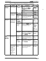
Table 1-19. Default Options
6.
Setting
Go to
Submenu
OFF
OFF
Character table
Page iength
Tabie 1-20
Table 1-21
Blinks
OFF
Skip over perforation
Tabie 1-22
ON
Biinks
OFF
Auto tear-off
Tabie 1-22
Biinks
OFF
ON
Graphic print direction
Tabie 1-23
Biinks
ON
ON
Software
Tabie 1-24
OFF
Biinks
ON
AGM
Tabie 1-22
ON
Biinks
ON
Auto line feed
Tabie 1-22
Biinks
OFF
Blinks
interface
Table 1-25
Biinks
ON
Blinks
Bit rate
Tabie 1-26
OFF
Biinks
Blinks
Parity bit
Table 1-27
ON
Biinks
Blinks
Data iength
Tabie 1-28
Biinks
Biinks
Blinks
ETWACK
Blinks
Biinks
OFF
I State reply
Font 1 Light
Font 2 Light
Pause Light
Blinks
Blinks
OFF
ON
OFF
,
Tabie 1-22
Tabie 1-22
When you reach the setting you want to change, press the Pause button once. The printer
automatically enters the submenu for that setting.
7. Press the Font button to move the through the settings in the submenu. The printer beeps
twice each time you press the Font button while in a submenu.
8. When the lights match your desired setting, press the Pause button to make your selection.
The printer saves the new setting and returns to the menu shown above.
9. Repeat steps 5 through 8 for each additional setting you want to change, or skip to step 10 to
exit the printer’s default setting mode.
10. When you are finished, turn the printer off. Any settings you have made remain in effect until
you change them again.
Table 1-20. Character Tables
Font 1 Light
Font 2 Light
Pause Light
Standard Modei
NLSP Modei
OFF
OFF
OFF
Pc 437
Pc 437
ON
OFF
OFF
PC 850
Pc 650
OFF
ON
OFF
Pc 860
PC 864
ON
ON
OFF
PC 863
PC 437 Greek
OFF
OFF
ON
PC 865
Pc 652
ON
OFF
ON
Pc 861
PC 853
OFF
ON
ON
BRASCII
PC 855
ON
ON
ON
PC 857
OFF
OFF
Blinks
AbicomD
—
ON
OFF
Blinks
—
PC 869
OFF
ON
Blinks
—
iSO Latin IT
ON
ON
Blinks
—
ISO 8859-7
OFF
Blinks
Blinks
—
Code MJK
ON
Blinks
Blinks
—
Mazowia
Blinks
Blinks
Blinks
—
Bulgaria
Rev. A
Pc 866
1-21
Product Description
LQ-300 Service Manual
Table 1-21. Page Length
Font 1 Light
Font 2 Light
Pause Light
Setting
OFF
OFF
OFF
11 inches
ON
OFF
OFF
12 inches
OFF
ON
OFF
ON
ON
OFF
8.5 inches
i’0/6 inches
. ..:.
. . .~
f
. .
Table 1-22. Skip Over Perforation / Auto Tear Off/ AGM / Auto Line Feed/
ETWACK / State Reply
Font 1 Light
Font 2 Light
Pause Light
Setting
OFF
OFF
OFF
off
ON
ON
ON
On
Table 1-23. Graphic Print Direction
Font 1 Light
Font 2 Light
Pause Light
Setting
OFF
OFF
OFF
Uni-D
ON
ON
ON
Bi-D
Table 1-24. Software
Font 1 Light
Font 2 Light
Pause Light
Setting
OFF
OFF
OFF
ESC/P2
ON
ON
ON
IBM X24E
Table 1-25. Interface
Font 1 Light
Font 2 Light
Pause Light
Setting
OFF
OFF
OFF
Auto selection (10 ms wait)
ON
OFF
OFF
Auto selection (30 ms wait)
OFF
ON
OFF
Parallel
ON
ON
OFF
Serial
Table 1-26.
1-22
gT’., ., .
Bit Rate
Font 1 Light
Font 2 Light
Pause Light
Setting
OFF
OFF
OFF
300 bps
ON
OFF
OFF
600 bps
OFF
ON
OFF
1200 bps
ON
ON
OFF
2400 bps
OFF
OFF
ON
4800 bps
ON
OFF
ON
9600 bps
OFF
ON
ON
19200 bps
Rev. A
Product Description
LQ-300 Service Manual
Table 1-27. Parity Bit
I
Font 1 Light
Font 2 Light
Pause Light
Setting
OFF
OFF
OFF
None
ON
OFF
OFF
OFF
ON
OFF
Even
I
1
Table 1-28. Data Length
I
Rev. A
Font 1 Light
Font 2 Light
Pause Light
Setting
OFF
OFF
OFF
7 bits
ON
ON
ON
8 bits
J
1-23
Product Description
LQ-300 Service Manual
1.5 MAIN COMPONENTS
The main components of the LQ-300 is designed for easy removal and repair. The main
components are:
■ C143 MAIN board: control board
■ C130 PSB/PSE (120 V/230 V) board: power supply board
■ M-5M1O: Printer mechanism
■ Housing
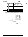
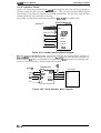
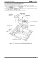
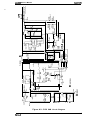
1.5.1 C143 MAIN Board
The C143 MAIN board consists of the TMP90C041 (CPU), an E05B02(GA), a program/CG ROM, a
PS-RAM, an EEPROM, etc.
PROM
(Program / CG)
PSRAM256K
TM P90C041 (CPU)
EEPROM
E05B02(GA)
4-2 SC5060
(PF Motor Driver)
a a o
\
o’/
6-STA475A
(Printhead Driver)
I
[
boll n
0 00
SLA7022M
/ _
(CR Motor Driver) /
UPC78M05AHF
(Regulator IC)
2-M51955B
(Reset IC)
\ (Color Option)
Figure 1-8. C143 MAIN Board Component Layout
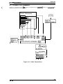
1.5.2 C130 PSB/PSE Board
The power supply boards are the same as those for the LX-300. The boards have two ratings for
input AC voltages: 120 VAC (C130 PSB) and 230 VAC (C130 PSE), Both boards consist of a
transformer, switching FETs, regulator IC, diode bridge, etc. The power supply board provides
+5 VDC and +35 VDC for the main board and printer mechanism.
Diode Bridge
Switching FET
Power Switch
Transformer
“n=.
(j yu--
nlu~uuul
nnnn
II
\
\
❑
~
—
m
1
I
1-----
l/--
/
Reaulator IC
Figure 1-9. C130 PSB/PSE Board Component Layout
1-24
Rev. A
Product Description
LQ-300 Service Manual
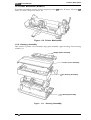
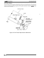
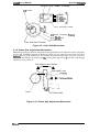
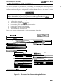
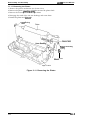
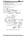
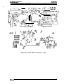
1.5.3 Printer Mechanism (M-5M1O)
The printer mechanism consists of 24-pin impact dot head, PF motor, RF motor, PE sensor, ~
sensor, PG sensor, release lever sensor, etc.
Figure 1-10. Printer Mechanism
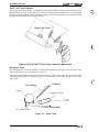
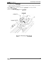
1.5.4. Housing Assembly
This consists of printer cover assembly, edge guide assembly, upper housing, lower housing
assembly, etc.
-= Edge Guide Assembly
Printer Cover Assembly
per Housing Assembly
r Housing Assembly
Figure 1-11. Housing Assembly
Rev. A
1-25
c
;“+
: !:,
- ,.. .
,,-,
f
~.
’,,,..
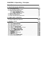
CHAPTER 2 Operating Principles
Table of Contents
2“1
2.1 PRINTER MECHANISM OPERATION
2.1.1 Printing Mechanism. . . . . . . . . . . . . . . . . . . . . . . . . . . . . . . . . . . . . . . . . 2-1
2.1.2 Carriage Movement Mechanism . . . . . . . . . . . . . . . . . . . . . . . . . . . . . . . 2-2
2.1.3 Paper Handling Mechanism. . . . . . . . . . . . . . . . . . . . . . . . . . . . . . . . . . . 2-3
2.1.3.1 Paper Feed Mechanisms. . . . . . . . . . . . . . . . . . . . . . . . . . . . . . . 2-3
2.1.3.2 PaperAdvance Mechanism . . . . . . . . . . . . . . . . . . . . . . . . . . . . . 2-3
2.1.4 Ribbon Advance Mechanism. . . . . . . . . . . . . . . . . . . . . . . . . . . . . . . . . . 2-7
2.1.5 Ribbon Shift Mechanism . . . . . . . . . . . . . . . . . . . . . . . . . . . . . . . . . . . . . 2-8
2.1.6 Platen GapAdjustment Mechanism . . . . . . . . . . . . . . . . . . . . . . . . . . . . 2-9
2-1o
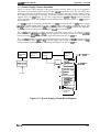
2.2 POWER SUPPLY OPERATION
2.2.1 Power Supply Overview. . . . . . . . . . . . . . . . . . . . . . . . . . . . . . . . . . . . . 2-10
2.2.2 Power Supply Circuit Operation. . . . . . . . . . . . . . . . . . . . . . . . . . . . . . . 2-11
2.3 CONTROL CIRCUIT
2-12
2.3.1 Control CircuitODeration overvie w . . . . . . . . . . . . . . . . . . . . . . . . . . . 2-12
2.3.2 Power On Reset’Circuit. . . . . . . . . . . . . . . . . . . . . . . . . . . . . . . . . . . . . 2-13
2.3.3 Power OffSensorCircuit. . . . . . . . . . . . . . . . . . . . . . . . . . . . . . . . . . . . 2-13
2.3.4 Home Position Sensor Circuit . . . . . . . . . . . . . . . . . . . . . . . . . . . . . . . . 2-14
2.3.5 Paper End SensorCircuit . . . . . . . . . . . . . . . . . . . . . . . . . . . . . . . . . . . 2-14
2.3.6 Release Lever Position Sensor Circuit . . . . . . . . . . . . . . . . . . . . . . . . . 2-14
2.3.7 Carriage MotorDriveCircuit . . . . . . . . . . . . . . . . . . . . . . . . . . . . . . . . . 2-15
2.3.8 Paper Feed MotorDriveCircuit . . . . . . . . . . . . . . . . . . . . . . . . . . . . . . . 2-16
2.3.9 Printhead Drive Circuit. . . . . . . . . . . . . . . . . . . . . . . . . . . . . . . . . . . . . . 2-16
2.3.10 Interface Circuit. . . . . . . . . . . . . . . . . . . . . . . . . . . . . . . . . . . . . . . . . . 2-17
2.3.11 EEPROM Control Circuit. . . . . . . . . . . . . . . . . . . . . . . . . . . . . . . . . . . 2-18
2.3.12 CS Motor Circuit . . . . . . . . . . . . . . . . . . . . . . . . . . . . . . . . . . . . . . . . . 2-18
2.3.13 Color Ribbon SensorCircuit . . . . . . . . . . . . . . . . . . . . . . . . . . . . . . . . 2-19
2.3.14 Platen GapSensorCircuit. . . . . . . . . . . . . . . . . . . . . . . . . . . . . . . . . . 2-19
List of Figures
Figure 2-1. Printhead Operation Principles . . . . . . . . . . . . . . . . . . . . . . . . . . . . 2-1
Figure 2-2. Carriage Movement Mechanism . . . . . . . . . . . . . . . . . . . . . . . . . . . 2-2
Figure 2-3. Friction Advance Mechanism. . . . . . . . . . . . . . . . . . . . . . . . . . . . . . 2-3
Figure 2-4. Push Tractor Paper Advance Mechanism . . . . . . . . . . . . . . . . . . . . 2-4
Figure 2-5. Pull Tractor Paper Advance Mechanism . . . . . . . . . . . . . . . . . . . . . 2-5
Figure 2-6. Push-Pull Tractor Paper Advance Mechanism. . ...............2-6
Figure 2-7. Paper Path. . . . . . . . . . . . . . . . . . . . . . . . . . . . . . . . . . . . . . . . . .. .2-6
Figure 2-8. Ribbon Advance Gear Linkage . . . . . . . . . . . . . . . . . . . . . . . . . . . . 2-7
Figure 2-9. Color Shift Mechanism. . . . . . . . . . . . . . . . . . . . . . . . . . . . . . . . . . . z-g
[;?
Figure 2-10. Platen Gap Adjustment Mechanism. . . . . . . . . . . . . . . . . . . . . . . . z-g
Figure 2-11. Power Supply Circuit Block Diagram . . . . . . . . . . . . . . . . . . . . . . 2-11
Figure 2-12. Control Circuit Block Diagram . . . . . . . . . . . . . . . . . . . . . . . . . . . 2-12
Figure 2-13. Power On Reset Circuit Diagram. . . . . . . . . . . . . . . . . . . . . . . . . Z-13
Figure 2-14. Power Off Sensor Circuit Diagram. . . . . . . . . . . . . . . . . . . . . . . . Z-13
Figure 2-15. Home Position Sensor Circuit Diagram . . . . . . . . . . . . . . . . . . . . 2-14
Figure 2-16. Paper End Sensor Circuit. . . . . . . . . . . . . . . . . . . . . . . . . . . . . . . 2-14
Figure 2-17. Release Lever Position Sensor Circuit Diagram . . . . . . . . . . . . . . 2-14
,s. -.
Figure 2-18. Carriage Motor Driver Circuit Diagram . . . . . . . . . . . . . . . . . . . . . 2-15 1~,..
Figure 2-19. Paper Feed Motor Driver Circuit Diagram . . . . . . . . . . . . . . . . . . 2-16
Figure 2-20. Printhead Driver Circuit Diagram . . . . . . . . . . . . . . . . . . . . . . . . . 2-17
Figure 2-21. Parallel Interface Block Diagram . . . . . . . . . . . . . . . . . . . . . . . . . 2-17
Figure 2-22. Serial Interface Block Diagram . . . . . . . . . . . . . . . . . . . . . . . . .
Figure 2-23. EEPROM Control Circuit Diagram. . . . . . . . . . . . . . . . . . . . . . .
Figure 2-24. CS Motor Assembly Circuit Diagram . . . . . . . . . . . . . . . . . . . . .
Figure 2-25. Color Ribbon Sensor Circuit Diagram . . . . . . . . . . . . . . . . . . . .
. 2-18
. 2-18
. Z-18
. 2-19
Figure 2-26. Platen Gap Sensor Circuit Diagram. . . . . . . . . . . . . . . . . . . . . . . 2-19
List of Tables
Table 2-1. CR Motor Specifications . . . . . . . . . . . . . . . . . . . . . . . . . . . . . . . . . . 2-2
Table 2-2. PF Motor Specifications . . . . . . . . . . . . . . . . . . . . . . . . . . . . . . . . . . 2-4
Table 2-3. Ribbon Advance Gear Linkage . . . . . . . . . . . . . . . . . . . . . . . . . . . . 2-7
Table 2-4. CS Motor Specifications . . . . . . . . . . . . . . . . . . . . . .............2-8
Table 2-5. Coloring Sequences . . . . . . . . . . . . . . . . . . . . . . . . . . . . . . . . . . . . . 2-8
Table 2-6. Power Supply Board . . . . . . . . . . . . . . . . . . . . . . . . . . . . . . . . . . . . 2-10
Table 2-7. Power Supply Output Voltages and Applications . . . . . . . . . . . . . . 2-10
Table 2-8. Functions of the Main [C. . . . . . . . . . . . . . . . . . . . . . . . . . . . .....2-12
Table 2-9. Carriage Motor Drive Modes. . . . . . . . . . . . . . . . . . . . . . . . . . . . . . 2-15
Operating Principles
LQ400 Service Manual
2.1 PRINTER MECHANISM OPERATION
This section describes the printer mechanism and explains how it works.
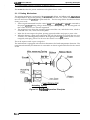
2.1.1 Printing Mechanism
The printing mechanism is composed of the prirdhead, ink ribbon, and ribbon mask. The printhead
is a 24pin head for impact dot printing. Each wire has own drive coil, which causes the wire to
move in and out of the printhead to print each dot. The four steps below describe how these
driving wires work.
1.
2.
3.
4.
A drive signal transmitted from the control arcuit to the printhead drive arcuit is converted to
the proper printhead driving voltage, which energizes a corresponding coil. The energized coil
then causes the iron core to become magnetized.
The magnetic force draws the actuating plate toward the core, and the dot wire, which is
connected to the core, rushes toward the platen.
When the dot wire impacts the platen, pressing against the ribbon and paper, it prints a dot.
When the driving voltage stops energizing the coil, the magnetic force from the iron core
vanishes. The actuating plate returns to its original position (the position before coil was
energized) with spring action. The dot wire also returns to its original position.
This is the sequence used to print a single dot.
The mechanism is equipped with a built-in thermistor for head temperature detection. The
temperature detected by the thermistor is converted to an electric signal and fed back to the control
circuit.
Wire Resettin S rin
Stopper
Dot Wire
.
Yn7YY2
77
r
\
Actuating Spring
Figure 2-1. Printhead Operation Principles
Rev.A
2-1
Operating Principles
LQ-300 Service Manual
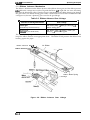
2.1.2 Carriage Movement Mechanism
The carriage movement mechanism consists of the carnage assembly, CR motor, timing belt, driven
pulley, HP sensor, etc. The CR motor drives the tirnkigbelt. The carnage assembly is connected to
the timing belt, which is moved by the CR motor. Figure 2-2 shows the carriage movement
mechanism.
The printer detects tie carriage home position with the HI? sensor. This sensor is the basis for
determin”mg the carriage home position. The HP sensor informs the CPU of the carriage home
position. The sensor is ON, when the carriage is pushed to the right or left. The striker on the
carriage actives the sensor to indicate the carriage home position, which toggles the sensor to OFF.
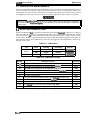
Table 2-1. CR Motor Assembly Specifications
I
Category
I
Requirement
Type
4-phase, 96-pole, HB-type stepping motor
Drive Voltaae
31.5 -38.5 VDC
I Coil Resistance
I
I
1 9 . 6 Q * 8 % (Der Dhase, at25° C,770 F) I
Drive Pulse Frequency
Normal Mode Draft
Color Mode LQ
Excitation Method
Constant-voltage
2400 PPS
1600 DDS
I
2-2 phase excitation
1-2 phase excitation
-1
F~
-.. ,.
Figure 2-2. Carriage Movement Mechanism
2-2
Rev.A
LQ-300 Service Manual
Oparating Principles
2.1.3 Paper Handling Mechanism
During normal operation, paper is fed to the printer, advanced to the specified position, and
ejected from the printer. These functions are performed by various paper handling mechanisms,
such as the &actors, rollers, and gears. This section describes the paper handling mechanism for
this printer.
2.1.3.1 Paper Feed Mechanisms
Cut sheets are fed by friction. Continuous paper is fed by a tractor. There are three ways to feed
with tractors: the push tractor method, the pull tractor method, and the push-pull tractor method.
During normal operation, the printer is set up with only one tractor, which functions as either a
push or a pull tractor, depending on where it is attached on the printer. To use the push-pull . .
tractor feed method, an optional tractor must be attached.
There are two ways to insert paper into the printer. Cut sheets use the top entrance and continuous
paper uses rear insertion.
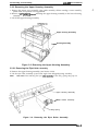
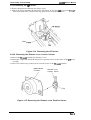
2.1.3.2 Paper Advance Mechanism
This section describes how the friction and tractor advance mechanisms feed paper through the
printer. The paper advance mechanism consists of the PF motor, platen, driven roller assembly,
driven roller cover, tractor assembly, knob, PF gear train, etc. The PF motor can drive the platen
both forward and in reveme.
Friction Advance Method
Paper is held by the platen, the PF driven roller, and the eject roller assembly. Turning in the
direction of the black arrows, the PF motor pinion gear drives the paper advance reduction gear.
The paper advance reduction gear turns the platen gear, PF driven roller, and the platen. The
platen drives the driven roller cover; then the driven roller cover drives to eject the paper. The
paper advances in the direction of white arrows. Figure 2-3 shows the friction advance method
when the paper is fed through the top paper entrance.
Driven Roller Cover
Driven PF Roller
Figure 2-3. Friction Advance Mechanism
Rev.A
2-3
LQ-300 Service Manual
Operating Principles
Table 2-2. PF Motor Specifications
Requirement
Category
Type
4-phase, 48-pole, PM-type stepping motor
Drive Voltage
31.5 -38.5 VDC
Coil Resistance
58.5 Q * 5% (per phase, at 25°C, 77°F)
Drive Pulse Frequency
800,900, 1000, 1200, 1300 ppS
Excitation Method
Constant-voltage 1-2 phase excitation
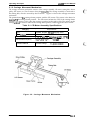
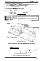
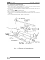
Push Tractor Method
When the push &actor method is used with the rear entrance, the torque generated by the PF motor
is transmitted to the push tractor gear through the PF motor pinion gear, the paper advance
reduction gear, and the tractor transmission gear. When the PF motor pinion gear turns in the
direction of the black arrows, the tractor gear rotates in the direction of the black arrow and thus
feeds the paper into the printer. The paper is advanced by the platen, which is also driven by the
PF motor through the gear train.
Continuous Paper
/
push Tractor
o
\
I ractor
/ Transmission Gear
/
5
~P
Tractor Gear
P&
‘b
-1.
\&@
PE Sensor
.
Platen
Reduction Gear
w-d
-0
/ ~ ‘aperAdvance
Driven Roller Cover
Platen Gear
Pinion Gear
\
PF Motor
Figure 2-4. Push Tractor Paper Advance Mechanism
Operating Principles
L WOO Service Manual
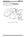
Pull Tractor Method
The pull tractor advances paper in basically the same way as the push tractor. When the push
tractor is installed at the paper exit instead of paper entrance, the tractor functions as a Pull tractor
instead of a push tractor, pulling the paper out of the printer mechanism. Figure 2-5 sho-ws the pull
tractor advance mechanism.
Continuous Paper
/hk/
..
,
Tractor
ear
PI
(/
(3”
PF Motor
0
Platen Gear
~d
Pinion Gear “ -
Figure 2-5. Pull Tractor Paper Advance Mechanism
Rev.A
2-5
operating Principles
LQ-300 Service Manual
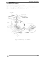
Push - Pull Tractor Method
The push-pull tractor method is a combination of the push method, using the standard tractor, and
the pull method, using an optional tractor. The two tractors operate simultaneously to push and
pull the paper through the printer mechanism. Figure 2-6 shows push-pull &actor operation when
the paper is fed through the rear paper entrance.
..’.%
t
. .,,
- -.,..,.
b
Figure 2-6. Push-Pull Tractor Paper Advance Mechanism
Disengage Lever
The disengage lever switches whether or not the printer transmits the torque of the PF motor to the
tractor transmission gear. (See Figures 2-5 and 2-6.)
The paper path is different from friction feed and tractor feed. The PF driven roller is not in the
tractor feed paper path, so continuous paper is not advanced by this roller. Figure 2-7 shows the
paper path.
Sheet Guide
.
,> Cut Sheet
Platen
Continuous paper
QY
\
<&Tractor
/
PE Sensor Assembly
PF Driven Roller
Figure 2-7. Paper Path
2-6
Rev.A
Operating Principles
LQ-300 Service Manual
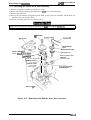
2.1.4 Ribbon Advance Mechanism
The ribbon is held between the ribbon advance roller (ribbon driven gear) and the ribbon pressure
roIler. When the carriage moves on the CR guide shaft from left to right and vice versa, the timing
belt turns the belt driven pulley. Then the torque is transmitted to the ribbon driving gear through
the gear trains. The ribbon driving gear rotates counterclockwise no matter what direction the
carriage moves, because a planetary gear is used in the gear linkage.
Table 2-3. Ribbon Advance Gear Linkage
I
)
1
Gear Linkage
Direction of Carriage Movement
Left to right
(indicated by the black arrow)
Belt driven pulley + Gear(1)+ Gear (2) -+
Ribbon driving gear
Right to light
irtdioated by the white arrow)
Belt driven pulley + Gear(1)+ Gear (3)+
Gear (4) + Ribbon driving gear
The ribbon brake spring, attached to the exit of the cartridge case, prevents slack in the ribbon and
keeps the ribbon tension at an appropriate level. The ribbon mask prevents the ribbon from
brushing against the paper.
Ribbon Advance Roller
\ &
Ink Ribbon
Ribbon Pressure
Mask
/
R
D
Ribbon Brake Spring
Carriage
Figure 2-8. Ribbon Advance Gear Linkage
Rev.A
2-7
Operating Principles
LQ-300 Service Manual
2.1.5 Ribbon Shift Mechanism
This printer can be equipped with a color upgrade kit to print in color. The printer performs color
printing unidirectionally. The option is composed of the color ribbon shift mechanism. The color
ribbon feed mechanism is shared in common with black ribbon feed mechanism, and the shift
mechanism shifts the ribbon cartridge up and down.
c’
-’$
.;.
. . . ..
Table 2-2 shows the CS motor specifications. The motor control system is open-loop, so that when
the color is being changed, the positioning is controlled by stepping pulse.
Table 2-4. CS Motor Specifications
Category
Requirement
Type
4-phase, 48-pole, PM-type stepping motor
Drive Voltage
35 VDC + 10%
Coil Resistance
150 Q * 5% (per phase, at 25° C or 77° F)
Drive Pulse Freauencv
Color shift 500
Excitation Method
I
DDS
I Constant-voltage 2-2 phase excitation
1
The ribbon shift mechanism consists of the color ribbon and color upgrade kit. The color upgrade
kit is composed of the CS motor, ribbon shift gear/cam, motor driver IC, and color ribbon sensor.
The 1-inch-wide color ribbon is separated into four equal-width bands of different colors. The
ribbon shift mechanism shifts the ribbon cartridge up and down.
When the color ribbon cartridge is loaded, it is possible to print in up to seven colors. One of the
four colors on the ribbon is selected by the color ribbon cartxidge motion, which inserts a portion of
the plastic posts into the slots in the printer mechanism as a fulcrum. Figure 2-9 illustrates the color
shift mechanism. The mechanism shifts the ribbon cartridge by converting the gear rotation to
liner motion (up and down) of the color ribbon cartridge, using color shift cam gear.
Any color band can be selected by rotation of the CS motor, using the color home position (the
position of the black color band) as a starting point and reference position. Home position is
recognized by the CS motor stepping pulse. When printer is powered on, the CS motor is first
exated at any phase position. Next, the CS motor is turned 235 steps ( black + yellow). Then, the
motor returns one step (yellow+ black), and the motor is stopped. Finally, the motor returns 223
steps (yellow+ black) and stops. This position is home position.
Table 2-5 gives coloring sequences. For halftones, as shown in the table, a color is created by
printing one color on top of another.
,*,
Table 2-5. Coloring Sequences
f
‘
-c .,
Print Ribbon
Print Color
I
I
Note:
2-8
First Printing
Second Printing
Black
Black
—
Magenta
Magenta
—
Cyan
Cyan
—
Yellow
I
Yellow
l
–
Green
Yellow
Cyan
Orange
Yellow
Magenta
Violet
I
Ma~enta
I
Cvan
l
I
The printer prints the brighter wlor first to prevent the ribbon from being stained,
Rev.A
Operating Principiea
LQ-300 Service Manual
Fulcrum Color Ribbon Cartridge
1/
CS Lever
//
Black
Cyan
Magenta
Yellow
~>
:
Color Cartridge Holder
CS Motor Assembly Pinion
Color Shift Cam
/
\
Color Shift Cam Follower
CS Cam Gear
Figure 2-9. Color Shift Mechanism
2.1.6 Platen Gap Adjustment Mechanism
The platen gap (the gap between the platen and the printhead) can be adjusted to allow the printer
to use paper of different weights or thicknesses. When the gap adjust lever is moved forward or
badcward, the CR guide shaft rotates. This rotation moves the carriage either toward or away from
the platen and changes the platen gap. lhe correct platen gap is 0.45 & 0.02 mm, with the gap
adjust lever set to position O.
Gap Adjust Lever Motion
PG
Gap Adjust Lever
—.. —..4
Platen
‘ \ CR Guide Shaft
Figure 2-10. Platen Gap Adjustment Mechanism
Rev.A
2-9
Operating Principles
L(?-300 Service Manual
2.2 POWER SUPPLY OPERATION
The printer can be powered by either of two power supply boards: the C130 PSB (120 V) or the
C130 PSE (230 V) power supply. These boards are the same as the LX-300’S power supplies. The
two boards function identically, except for a difference in primary circuitry. The power supply
board outputs the DC current necessary to drive the printer control circuits and drive mechanism.
Table 2-6 shows the input voltages and fuse ratings for these boards.
c
,’ ‘%
Table 2-6. Power Supply Board
Board
Input Voltage
Fuse F1 Rating
C130 PSB
100.5-132 VAC
2.5A 1125 V, 250 V
C130 PSE
198-264 VAC
1.25 A 1250 V
2.2.1 Power Supply Overview
The power supply board has two power outputs for use in the various control circuits and drive
mechanisms. Table 2-7 lists the circuitry and the units that are driven by the two DC output supply
voltages.
Table 2-7. Power Supply Output Voltages and Applications
output supply
Voltage (DC)
Applications
CR motor drivers
+35 v (VP)
PF motor drivers
Printhead drivers
CS motor drivers
Main board assembly logic circuitry
+9 V (VL)
Various sensors
Control panel LED
PF motor/ CS motor hold
. ~.,
..-
f
..; ‘
2-10
Rev.A
LQ-300 Service Manual
Operating Principle
2.2.2 Power Supply Circuit Operation
Figure 2-11 shows a block diagram of the power supply circuitry. When AC power is supplied to
the printer from an external power source, a filter cinmit removes the noise. The AC voltage then
undergoes full-wave rectification and is smoothed to produce the direct current supply voltage.
This voltage is fed through a switching circuit and secondary smoothing circuit to produce the
stepped down +35 VDC supply. A +35 V line voltage detector (ZD51 and PC1) circuit is connected
to the switching circuit. This feedback control arrangement ensures that the +35 VDC supply is
kept stabilized.
A +9 VDC supply is created by putting the +35 VDC line through the +9 VDC power supply
cimuit. This circuit further steps down the +35 VDC voltage and outputs a stabilized supply. The
+9 VDC output is stabilized to +5 VDC using the regulator on the C130 MAIN board assembly.
There are several circuits to protect the supply arcuits and avoid danger.
The +9 VDC line contains a voltage overload protection circuit. The +9 V voltage overload
protection circuit (ZD53, Q82, and PC1) cuts the supply if the voltage reaches or exceeds +11 VDC.
It stops switching arcuit operation, which stops the output from the +35 VDC line.
The +35 VDC line has a voltage overload protection circuit. The +35 VDC voltage overload
protection circuit ( ZD52, Q82, and PC1 ) cuts the supply if the voltage reaches or exceeds +36 VDC.
It stops switching circuit operation, which stops the output from the +35 VDC line.
Full-Wave
Rectification —
Circuit
T
Switching
Circuit
Smoothing
Circuit
Smoothing
Circuit
4
-+9 VDC (VL)
Filter Circuit
AC Line
~ +35 VDC (VP)
-Ez!t
c1
+9 VDC Line
Over-voltage
Protection
Circuit
I +35 VDC Linel
— Over-voltage
Protection
t
Circuit
I
I
Figure 2-11. Power Supply Circuit Block Diagram
Rev.A
2-11
Operating Principles
LQ-300 Service Manual
2.3 CONTROL CIRCUIT
The control circuit consists of the C143 MAIN board assembly. This section desuibes the major
components and explains how the board works.
2.3.1 Control Circuit Operation Overview
The printer has a CPU (TMP90C041) that runs at 9.8304 MHz, a gate array (E05B02-type), a
PS-RAM (256K-bit), a ROM (4 or 8M-bit), etc. It oversees control of all the components in the
printer. The printer uses the E05B02 gate array to control memory management, parallel
communications, PF motor drive signals, etc. Table 2-8 shows functions of ICS and circuits. Figure
2-12 shows the control circuits in bl&k diagram form.
Table 2-8. Functions of the Main IC
Ic
I Location
Function
ICI
Receives data from the host computer and sends it to the input buffer
in RAM (under interrupt processing control). Extends the input data
held in the buffer to create image data. Loads this image data to the
image buffer in RAM. Transfers the image data to the Printhead
drive circuit. Also controls various parts of the printer mechanism,
such as PF motor control and color select motor control.
CPU
I
IC2
Controls the functions below:
● Input/Output Control
● Memory Management
. Bit Manipulation
● Interface Control
. Expanded Parallel Port
. Printhead Control
● Motor Control
IC3
An electrically writable and erasable ROM used to hold such
information as the TOF position and bidirectional adjustment value.
+
EEPROM
Driver / receiver
Hardware reset function
Power off detection
R----R-
Contains the program that runs the CPU and holds the character
design (also called the charaoter generator).
-.,
f,., .-
Input buffer
I
1
I Printhead DRV.
I
A
I
L
Printhead Temp.
Sensor
Power Off Sensor
1
1
v
I
*
Panel
SWILED ~
Gate Array
<
+35 V Sensor
4
PE Sensor
1
Parallel l/F
EEPROM
&kiiEl
RESET
‘
p
”
Y
4
Release Lever Sensor
D
A
Serial l/F
Color Ribbon Sensor
...
Figure 2-12. Control Circuit Block Diagram
2-12
Rev.A
LWOO Service Manual
Operating Principles
2.3.2 Power On Reset Circuit
When the power supply is turned on and immediately the VL (+9 V) goes up to +7.5 V (typical), the
reset IC (IC6) outputs the system RESET signal (LOW). The CPU and gate array receive this LOW
level signal from the reset IC and reset themselves.
67
i
XRST
A VL
16
RESET
4b
GATE ARRAY
(IC2)
3
CPU
(IC6)
()
3
L
(ICI)
Vcc ~
2
IN
4
GND O U T 6
z+
Fgiure 2-13. Power On Reset Circuit Diagram
2.3.3 Power Off Sensor Circuit
When the power supply is turned off and the VP (+35V) immediately goes down to +25 V (typical),
the reset IC (IC7) outputs the system RFSETsignal (LOW). The CPUreceives this LOW Ievelsignal
from the reset IC and resets itself.
+5
4
VP
Power Off
Sensor IC (IC7)
4 L Vcc
IN
t
2
15
1
+i’-
I
7+7
Figure 2-14. Power Off Sensor Circuit Diagram
Rev.A
2-13
Operating Principles
LQ-300 Service Manual
2.3.4 Home Position Sensor Circuit
This printer has a connector switch to sense the carriage home position. The CPU receives a signal
from the HP sensor and recognizes the carriage home position when the printer is turned on. The
comector switch is open (OFF) when the carriage is in the home position and is closed (ON) when
the carriage is out of home position.
+5 v
CPU (ICI)
1
Home Position
Sensor
2
P551AN5
4)
“
Figure 2-15. Home Position Sensor Circuit Diagram
(..;
2.3.5 Paper End Sensor Circuit
This printer has a comector switch for sensing the paper end. The CPU receives a signal from the
connector switch and reco~es a paper
. . end. The connector switch is closed (ON) when there is
no paper on the platen and is open (OFF) when paper is present.
+5 v
t
CPU (ICI)
E
P52JAN2
PE Sensor
63
Figure 2-16. Paper End Sensor Circuit
2.3.6 Release Lever Position Sensor Circuit
This printer has a connector switch to detect the type of paper handling. The CPU receives a signal
from the connector switch to indicate whether the paper is fed using friction or hactor feed. The
connector switch is closed (OFF) when friction feed is selected and is open (ON) when tractor feed
is selected.
CPU (lCl)
1
Release Lever
Position Sensor
P53/AN3
Figure 2-17. Release Lever Position Sensor Circuit Diagram
2-14
Rev.A
L WOO Service Manual
Operating Principles
2.3.7 Carriage Motor Driver Circuit
Figure 2-18 shows the carriage motor driver circuit. The carriage motor driver uses an open-Ioop,
constant-current chopping drive arrangement. The motor is driven with 2-2 phase excitation and
1-2 phase excitation.
The MOO-3 (pins 3-6) on the CPU are used to control the phases of stepping motor. The carriage
motor driver IC (IC8) detects the amount of current in the carnage motor coils and regulates the
current. The amount of current flowing in the coils varies, depending on the speed of the carriage
motor. The amount of the cument is set by the gate array (IC2). Signals are sent to the ODO-0D2
on the CPU. ODENO-1 and OPHO-1 on the CPU control the stepping motor.
Table 2-9. Carriage Motor Drive
Modes
Driver Mode
Excitation Type
3 x speed
2-2 phase
2400
2 X speed
2-2 phase
1600 PPS
Draft Copy Mode
3/2 X speed
2-2 phase
1200 pps
Bit Image Mode
1 X speed
1-2 phase
1600 ppS
LQ Mode
3/4 x speed
1-2 phase
1200 pps
LQ Copy Mode
1/2 x speed
1-2 phase
800 PPS
LQ Speed Down Mode
Drive Frequency Type
PPS
Standard Print Character
Draft Mode
+5V +5V
CR Motor
Driver IC ( ;8)
GATE ARRAY IC2)
H
ODEN1
OPH1
CR MOTOR
T
OA .
O-A
0 0 10
o - B 15
ODENO
OPHO
Vx
46
OD2 72
OD1
B2
ODO
CRA
CR_A
CRB
CR_B
Vx
3
‘IIIJ
t-
CRCOM
n
Jr
Figure 2-18. Carriage Motor Driver Circuit Diagram
Rev.A
2-15
Operating Principles
LC&300 Service Manual
2.3.8 Paper Feed Motor Driver Circuit
Figure 2-19 shows the paper feed motor driver circuit, an open-loop, constant-voltage drive with
1-2 phase excitation.
.c, \
The ports (pins 7-lo) on the CPU are used to control the stepping motor. The pulse signal from the
IC1 controls four tmmsistors and the stepping motor. The motor is driven at six speeds, 300,500,
600, 1000, 1200, and 1300 pps, to correspond to the idling voltage, the paper handling condition,
and the volume of paper feeding. The CPU controls motor driving speed. At the holding time, the
PFCOM voltage is changed VX (+35 V) into VL (+5 V) via Q1 and Q6 by the gate array.
CPU (ICI)
Gate Array
E
M13
M12
Mll
MIO
143
I
PF Motor Drive
Transistors
PF-~
Q2
!37
!W
Q3
PF_A
139
Q4
PF~
140
Q5
P FA
==%
A4 &
+5V
.c,
.,
., .
k---wTpFcOM
~-
1
J‘
VL
Vx
Figure 2-19. Paper Feed Motor Driver Circuit Diagram
2.3.9 Printhead Driver Circuit
Figure 2-20 shows the printhead driver circuit block diagram. Print data, already expanded into
image data is split by the CPU and transferred to the latch circuit in the gate array in the system.
Port AN6 (pin 66) of IC1 samples the voltage of the +35 VDC line via the A/D converter. By
sampling the +35 VDC line voltage and deterrninin g the length of the head drive signal, it is
possible to maintain the energy supplied to the head at a constant level. If the voltage from the
+35 V line is HIGH, ICI shortens the output puke. If the voltage from the +35 VDC line is LOW,
ICI lengthens the output pulse.
VP
CPU
Gate Array
QM1 -6
--h
,
●
DATA
BUS
●
●
●
●
●
●
●
y
:
+!
9
-vW-
●
●
●
●
●
●
●
●
#l
f
i
●
,
b
●
+5 v VP
ANI
#24
A=
62
Id
d
-1-
Figure 2-20. Printhead Driver Circuit Diagram
2-16
Rev.A
,-,,
‘
Operating Principles
LQ-300 Service Manual
2.3.10 Interface Circuit
Figure 2-21 shows the parallel interface arcuit block diagram. Data from the host computer is
latched within the gate array by STROBE signal. The gate array outputs XBUSY signal
automatically to stop the host computer from sending further data. The gate array reads the data
latched periodically with generating an interrupt.
The parallel I/F conforms to bidirectional parallel I/F IEEE-P1284 level 1 nibble mode.
Gate Array (IC2)
Parallel l/F
127-134
DINO-7
39
~ - - - - -: XSTROB
13
; XB”SY
4
---12 ‘
~ ------ XPE
4
14
4
------ XERR
15
4
------ XSLCT
4
L ‘ - - -” - XSLIN
Figure 2-21. Parallel Interface Block Diagram
Fim.ue 2-22 shows the serial interface circuit block diagram. The serial interface conforms to
E&232D. RXD is data received by the serial 1/0 of th~CPU block from the host computer via
driver/receiver IC4. Data is transmitted to an input buffer in IC1l from the CPU. Printing starts
when a CR code is received or when the input buffer is filled.
+5V
Serial IIF
TXD 4
DTR 4
RXD
CTS
Driver/Receiver
(IC4)
.,
. D1OUT
D20UT
F RIIN
+ R21N
DIIN
D21N
R1OUT
R20UT
t
?
~
CPU (lCl)
53
P33
52
P32
50
P30
54 P34
RST
Figure 2-22. Serial Interface Block Diagram
Rev.A
2-17
LQ-300 Service Manual
Operating Principles
2.3.11 EEPROM Control Circuit
Figure 2-23 shows the EEPROM control circuit block diagram. The EEPROM (IC6) contains such
information as the top-of-form position. The EEPROM is non-volatile memory, so information is
not lost if the printer is powered off. Since the EEPROM is a serial I/O-type device, the CPU
converts 8-bit data into serial data.
CPU (lCl)
EEPROM (IC3)
05
3
38
‘
A
Vcc L}
2 CK
06
07
Cs
+5 v
3
::5
DI
4 ’ DO
17
)
GND
+’7Figure 2-23. EEPROM Control Circuit Diagram
2.3.12 CS Motor Circuit
Figure 2-24 shows a block diagram of the CS motor circuit in the optional color upgrade kit. The
CS motor is a permanent magnet (PM) stepping motor, driven with 2-2 phase exatation in
proportion to the desired rotational speed. This motor can be rotated in either direction and
stopped at any position. Four phase signals are directly output from the system IC and pass
through a tcansistorarray. The drive voltage is constant (i.e., +35 VDC from the VP line).
Source Voltage
Current Consumption
35 VDc * 10
245 mA ( peak)
?40
I
I
1
GATE ARRAY (IC2)
-
I=%z
i
MT3
MT2
MT1
MTO
CS MOTOR
Q1
9
CS-B
49
CS-A
4a
CS B
47
CS A
CS-HOLD
04 *
Printer
I
Color Upgrade Kit
Figure 2-24. CS Motor Circuit
. .-
2-18
Rev.A
Operating PrinciMes
LQ-300 Service Manual
2.3.13 Color Ribbon Sensor Circuit
The printer’s color ribbon circuitry is shown in the figure below. The CPU receives signals (HIGH
or LOW) from the mechanical switch. The signal is HIGH (ON) when a color ribbon is installed
and is LOW (OFF) otherwise.
+5 v
CPU (Cl)
tl
1] Color Ribbon Sensor
I
51
P31
I
; Color Upgrade Kit
Printer
I
Figure 2-25. Color Ribbon Sensor Circuit Diagram
2.3.14 Platen Gap Sensor Circuit
This printer has a connector switch to sense the PG(Platen Gap) adjust lever position. The CPU
receives a signal from the PG sensor and recognizes the PG adjust lever position. The comector
switch is open(OFF) when the printer is in copy mode(PG adjust lever position:2-6) and is
close(ON) when the printer is in normal mode(PG adjust lever position:-l-+l). The printing speed
decrease in copy mode.
+5V
CPU (ICI)
P54
t
1
Figure 2-26. Platen Gap Sensor Circuit Diagram
Rev.A
2-19
4?
CHAPTER 3 Disassembly and Assembly
Table of Contents
3.1 OVERVIEW
3.1.1 Disassembly Precautions . . . . . . . . . . . . . . . . . . . . . . . . . . . . . . . . . . . .
3.1.2 Tools . . . . . . . . . . . . . . . . . . . . . . . . . . . . . - - .”.-...”” ““”.””””””””
3.1.3 Service ChecksAfterRepair . . . . . . . . . . . . . . . . . . . . . . . . . . . . . . . . . .
3.1.4 Specifications forScreWs. . . . . . . . . . . . . . . .. ... ... ...”O”” ....”.”
3-1
3-1
3-1
3-2
3-3
3-4
3.2 DISASSEMBLY AND ASSEMBLY
3.2.1 Removing the Printhead . . . . . . . . . . . . . . . . . ........””””-””. ““.” 3-5
3.2.2 Removing the Upper Housing Assembly. . . . . . . . . . . . . . . . . . . . . . . . . 3-6
3.2.2.1 Removinq the Eject Roller Assembly “.””” .s s””””””” o -”” -” 3-6
—
3.2.3 Removingthe MAIN and PSB/PSE BoardAssembfies . . . . . . . . . . . . . . 3-7
3.2.3.1 Removing the MAIN Board Assembly. . . . . . . . . . . . . . . . . . . . . 3-8
3.2.3.2 Removing the PSB/PSE Board Assembly. . . . . . . . . . . . . . . . . . 3-8
3.2.4 Removing the Printer Mechanism . . . . . . . . . . . . . . . . . . . . . . “ . . . “ “ “ - 3-9
3.2.4.1 Removing the PF Motor . . . . . . . . . . . . . . . . . . . . . .. ------- 3-10
3.2.4.2 Removing the CR Motor. . . . . . . . . . . . . . . . . . . . . . . . . . . . . . 3-11
3.2.4.3 Removing the Platen. . . . . . . . . . . . . . . . . . . . . . . . .””. “ -.. “ 3-12
3.2.4.4 Removing the PE Sensor . . . . . . . . . . . . . . . . . . . . . . . . . . . . . 3-13
3.2.4.5 Removing the HP Sensor. . . . . . . . . . . . . . . . . . . . . . . . . . . . . 3-14
3.2.4.6 Removing the Release Lever Position Sensor . . . . . . . . . . . . . 3-14
3.2.4.7 Removing the Carriage Assembly. . . . . . . . . . . . . . . . . . . . . . . 3-15
3.2.4.8 Removing the Ribbon Drive Gear Assembly. . . . . . . . . . . . . . . 3-16
3.2.4.9 Removing the PG Sensor. . . . . . . . . . . . . . . . . . . . . . . . . . . . . 3-17
3.2.5 Removing the Interface Board Assembly. . . . . . . . . . . . . . . . . . . . . . . . 3-18
3.2.6 Removing the Driven Roller Assembly . . . . . . . . . . . . . . . . . . . . . . . . . $19
3.2.7 Disassembling and Assembling the Color Upgrade Kit. . . . . . . . . . . . . 3-20
3.2.7.1 Removing the Ribbon Motor Assembly. . . . . . . . . . . . . . . . . . . 3-20
3.2.7.2 Removing the CS Cam. . . . . . . . . . . . . . . . . . . . . . . . . . . . . . “ 3-20
3.2.7.3 Removing the Color Sensor Assembly. . . . . . . . . . . . . . . . . . . 3-20
CHAPTER 3 Disassembly and Assembly
Table of Contents
3-1
3.1 OVERVIEW
3.1.1 Disassembly Precautions . . . . . . . . . . . . . . . . . . . . . . . . . . . . . . . . . . . . 3-1
3.1.2 ToOIS . . . . . . . . . . . . . . . . . . . . . . . . . . . . . . . . . . . . . . . . . . . . . . . . . . . . 3-1
3.1.3 Service ChecksAfterRepair . . . . . . . . . . . . . . . . . . . . . . . . . . . . . . . . . . 3-2
3.1.4 Specificationsfor Screws. . . . . . . . . . . . . . . . . . . . . . . . . . . . . . . . . . . . . 3-3
3-4
3.2 DISASSEMBLY AND ASSEMBLY
3.2.1 Removing the Printhead . . . . . . . . . . . . . . . . . . . . . . . . . . . . . . . . . . . . . 3-5
3.2.2 Removing the Upper Housing Assembly. . . . . . . . . . . . . . . . . . . . . . . . . 3-6
3.2.2.1 Removing the Eject Roller Assembly . . . . . . . . . . . . . . . . . . . . . 3-6
3.2.3 Removing the MAIN and PSB/PSE Board Assemblies. . . . . . . . . . . . . . 3-7
3.2.3.1 Removing the MAIN Board Assembly. . . . . . . . . . . . . . . . . . . . . 3-8
3.2.3.2 Removing the PSB/PSE Board Assembly. . . . . . . . . . . . . . . . . . 3-8
3.2.4 Removing the Printer Mechanism . . . . . . . . . . . . . . . . . . . . . . . . . . . . . . 3-9
3.2.4.1 Removing the PF Motor . . . . . . . . . . . . . . . . . . . . . . . . . . . . . . 3-10
3.2.4.2 Removing the CR Motor. . . . . . . . . . . . . . . . . . . . . . . . . . . . . . 3-11
3.2.4.3 Removing the Platen. . . . . . . . . . . . . . . . . . . . . . . . . . . . . . . . . 3-12
3.2.4.4 Removing the PE Sensor . . . . . . . . . . . . . . . . . . . . . . . . . . . . . 3-13
3.2.4.5 Removing the HP Sensor. ., . . . . . . . . . . . . . . . . . . . . . . . . . . 3-14
3.2.4.6 Removing the Release Lever Position Sensor . . . . . . . . . . . . . 3-14
3.2.4.7 Removing the Carriage Assembly. . . . . . . . . . . . . . . . . . . . . . . 3-15
3.2.4.8 Removing the Ribbon Drive Gear Assembly. . . . . . . . . . . . . . . 3-16
3.2.4.9 Removing the PG Sensor. . . . . . . . . . . . . . . . . . . . . . . . . . . . . 3-17
3.2.5 Removing the Interface Board Assembly. . . . . . . . . . . . . . . . . . . . . . . . 3-18
3.2.6 Removing the Driven Roller Assembly . . . . . . . . . . . . . . . . . . . . . . . . . 3-19
3.2.7 Disassembling and Assembling the Color Upgrade Kit. . . . . . . . . . . . . 3-20
3.2.7.1 Removing the Ribbon Motor Assembly. . . . . . . . . . . . . . . . . . . 3-20
3.2.7.2 Removing the CS Cam. . . . . . . . . . . . . . . . . . . . . . . . . . . . . . . 3-20
3.2.7.3 Removing the Color Sensor Assembly. . . . . . . . . . . . . . . . . . . 3-20
Disassembly and Assembly
LQ-300 Service Manual
3.1 OVERVIEW
This section describes various points to note when disassembling and assembling the printer.
3.1.1 Disassembly Precautions
Follow the precautions below when disassembling the printer.
Before disassembling, assembling, or adjusting the printer, disconnect the power supply
cablefiom the AC power socket. Failure to do so can cause personal injuy.
To maintain efi”cient printer operation:
● Use only the recommended tools for maintenance work.
● Use only the recommended lubn”cants and adhesives (see Chapter 6).
. Adjust the pn”nter only in the manner described in this manual.
3.1.2 Tools
Tables 3-1 and 3-2 list the tools recommended for disassembling, assembling, or adjusting the
printer. Use only tools that meet these specifications.
Table 3-1. Recommended Tools
Part No.
Tool
Note:
Round-nose pliers
6740400100
Nippers
B7405OO1OO
Tweezers
6741000100
Soldering iron
B7402OO1OO
E-ring holder #2.5
6740800400
Phillips screwdriver No.2
6743800200
Normal screwdriver
6743000100
Thickness gauge
6776702201
All tools are commercially available.
Table 3-2. Equipment Required for Maintenance
Description
Specification
Multimeter
Oscilloscope
Note:
Rev.A
50 MHz
An oscilloswpe is required only for servicers who repair to the component level.
3-1
LQ-300 Service Manual
Disassembly and Assembly
3.1.3 Service Checks After Repair
Before returning the printer after service, use the checklist in Table 3-3, which provides a record to
make servicing and shipping more effiaent.
Table 3-3. Inspection Check list for Repaired Printer
Category Component
Printer
units
Printhead
Item to Check
Are any wires broken?
Are any wires worn out?
Carriage
mechanism
Does the oarriage move smoothly?
❑ Movement noisy Q Mechanism dirty
❑ Mechanism oily
Is the CR motor at the
oorrect temperature (not overheating)
Paper
advance
mechanism
Is paper advancing smoothly?
❑ Movement noisya Mechanism dirty
❑ Mechanism oily
Is the paper advanoe motor running
at the correct temperature (not
overheating)
Paper path
Is the &oe of paper in the printer
feeding smoothly?
Is the tractor feeding the paper
correctly?
Is the paper path clear of all
obstructions?
❑ Checked UNot necessary
❑
Checkedn Not neoessary
❑ Checked ❑ Not neoessary
❑ Checked ❑ Not neoessary
❑ Checkedn Not neoessary
❑ Checked ❑ Not neoessary
Ribbon
mask
Is the ribbon mask free of distortion?
Self-print
test
Was the self-print successful?
❑ Checked ❑ Not
On-line test Was the on-line test successful?
Adjustment Printhead
printing
Is the platen gap adjusted correctly?
Is the bidirectional print position
adjusted oorreotly?
Default
setting
Have user-ohangeable settings been
reset to the default value?
ROM
version
ROM version
Shipment
Has the ribbon been removed?
Have all relevant parts been included
in the shipment?
3-2
❑ Checked ❑ Not necessary
❑ Checkeda Not neoessary
❑ Checked D Not neoessary
❑ Checked ❑ Not neoessaty
❑ Checkedn Not necessary
Is the platen free of damage?
System
upgrade
Is Check Required?
necessary
❑ Checked ❑ Not necessary
❑ Checked ❑ Not necessary
❑ Checked D Not necessary
❑ Checked ❑ Not
necessary
❑ Checked ❑ Not
necessary
❑ Checked ❑ Not
❑ Checked ❑ Not
necessary
necessary
Rev.A
.
Disassembly and Assembly
LQ-300 Service Manual
3.1.4 Specifications for Screws
Table 3-4 lists the abbreviations used in the following sections for small parts, such as screws and
washers.
Table 3-4. Screw Abbreviations
Abbreviation
CP
Cross-recessed pan head screw
CPB
Cross-recessed pan head B-tight screw
CBB
Cross-recessed bind head B-tight screw
CBS
Cross-recessed bind head S-tight screw
CBC
Cross-recessed bind head C-Lamitite screw
CB(0)
CFP
Rev.A
Part Name
Cross-recessed bind head with outside toothed lock washer
Cross-recessed flat head P-tight screw
3-3
LQ+?O Service Manual
Disassembly and Assembly
3.2 DISASSEMBLY AND ASSEMBLY
This section describes the procedures for disassembling and assembling the main components of
the printer. When the procedure for installing a component is simply the reverse of the procedure
for removing the component, no description of the installation is given. Any points of special
concern follow the description of the procedure.
●
●
Before disassembling any part of the printer, note the warnings in Section 3.1.
Before disassembling any part of the printer, remove the paper and the ink rt”bbon.
Disassembly includes the following seven procedures:
1.
2.
3.
4.
5.
6.
7.
Removing the printhead.
Removing the upper housing assembly.
Removing the MAIN and PSB/PSE board assemblies.
Removing the printer mechanism.
Removing the interface board assembly.
Disassembling the driven roller assembly.
Disassembling the color upgrade kit
Refer to the diagrams in the appendix to see how components fit together.
I
START
I
1
Unplug the power cable and the
I interface cable from h prfntart
I
Removing the Driven RollerAawmbly
3.2.2.1
Rem-wing the Upper Housing Assembly
I1
Rerswing the Ejecl Roller AexmMy
Removing the MAIN andPSB/ PSE Boerd Assemblies
I
E&
I 3-9
!echsnism
3.2.4.1
Removing the PF Motor
Removirw the CR Motor
i
3.2.4.3
Removing the Platen
13-12
Renwma the PE Sensor
3.2.4.5
Removing the Release Lever Position Sensor
I
1
3.2.4.8
] 3-16
Rernowng the Rtbb@ Drive Gear Aaeembly
Removmg the Carnage Assembly
3.2.4.9
Removing the PG Sensor
3.2.5
I 3-18
Removing the Interface Board Assembly
I
3-17
I
I
I
Figure 3-1. Procedure for Disassembling the Printer
3-4
Rev.A
,’
Disassembly and Assembly
LQ-300 Service Manual
3.2.1 Removing the Printhead
Remove the printer cover assembly, edge guide assembly, ribbon cartridge, tractor assembly,
platen knob, and color upgrade kit.
2. Remove the CPB (M3 x 14) screw attaching the printhead to the carnage assembly.
3. Remove the printhead.
4. Remove the head cables (FFCS) from the printhead.
1.
Printhead
FC
Fgiure 3-2. Removing the Printhead
Rev.A
3-5
LQ-300 Service Manual
Disassembly and Assembly
3.2.2 Removing the Upper Housing Assembly
1. Remove the printer cover assembly, edge guide assembly, ribbon cartridge, tractor assembly,
platen knob, and optional color upgrade kit.
2. Remove 4 CPB (M4 x 12) screws attaching the upper housing assembly to the lower housing
assembly.
3. Lift off the upper housing assembly.
Upper Housing Assembly
Housing Assembly
Figure 3-3. Removing the Upper Housing Assembly
3.2.2.1 Removing the Eject Roller Assembly
1. Remove the upper housing assembly ( see Section 3.221).
2. Lift the eject roller assembly up and atan angle from theupperhousing assembly.
Note:
User care when removing the eject ro//erassemb/y, or the 500 g spring may pop out.
Upper Housing Assembly
~ Eject Roller Assembly
‘N
v
= 500g Spring
Figure 3-4. Removing the Eject Roller Assembly
3-6
Rev.A
Disassembly and Assembly
LC?-300 Service Manual
3.2.3 Removing the MAIN and PSB/PSE Board Assemblies
1.
2.
3.
4.
5.
Remove the printer cover assembly, edge guide assembly, ribbon cartridge, tractor assembly,
platen knob, and optional color upgrade kit.
Remove the upper housing assembly (see Section 3.2.2).
Disconnect 4 flexible flat cables (FFCS) and 7 connectors from the MAIN and PSB/PSE board
assemblies.
Remove 4 CBB (M3 x 8) screws attaching the shield plate to the MAIN and PSB/PSE board
assemblies, the CBB (M3 x 8) screw attaching the CS board, and the CB(0) (M4 x 8) screw
attaching the ground wire of the power cable.
Disengage the shield plate and W and PSB/PSE board assemblies from the grounding
plate.
CBB(M3X8)
PSB/PSE Board AssemblY
MA
/
Shield Plate
M4x8)
round Wire
CBB(
er Cable
Grounding Plate
Figure 3-5. Removing the Shield Plate
Rev.A
3-7
Disassembly and Assembly
LQ-300 Service Manual
3.2.3.1 Removing the MAIN Board Assembly
1. Remove the PSB/PSEboard assembly FFC fromconnector CN20fthe MAIN board assembly.
2. Remove the CBC (M3x8)screwand the3CBUSCAC (M3 x8).
3. Remove the MAIN board assembly.
3.2.3.2 Removing the PSB/PSE Board Assembly
1. Remove the FFC for the PSB/F’SE board assembly from connector CN2 on the MAIN board
assembly.
2. Remove he CB USCA C (M3 x 10) screw and 2 CB USCA C (M3 x 8) screws.
3. Remove the PSB/PSEboard assembly.
When replacing the MAIN board assembly, bend the LED lead wires parallel to the MAIN
board assembly (see Figure 3-7).
● The shield plate is easily bent; be carefil when tightening the screws that attach it to the
MAW and PSBIPSE board assemblies.
●
CBUSCA C(M3X1O)
CBUSCA C(M3X8)
CBUSCA C(M3X8)
CBC(M3X8)
\
FFc shield P l a t e CBUSCAC(M3X8)
\,
/
.
,1,
.
*A
\@
\f\/’#J@?y
<’
$
/
PSB/PSE Board Assembly
~~Q
~’
MAIN Board Assembly
u
Figure 3-6. Removing MAIN and PSB/PSE Board Assemblies
MAIN Board Assembly
\
Figure 3-7. Bending the LED Lead Wires
3-8
Rev.A
LQ-300 Service Manual
Disassembly and Assembly
3.2.4 Removing the Printer Mechanism
1. Remove tie Pfiter cover assemblies, edge guide assemblies, ribbon cartridge, tractor
assemblies, platen knob, and optional color upgrade kit.
2. Remove the upper housing assembly (see Section 3.2.2).
3. Remove the connectors and FFCS from the MAIN board assembly.
4. Remove the 3 lower housing shafts (1018296).
5. Remove the other lower housing shaft (1015457). (Note that this shaft is different from the
three described in the previous step.)
Remove the printer mechanism.
6
Lower Housing
Shaft (101 8296)
Lower Housing
Shaft (1015457)
n
Lower Housing Assembly
Figure 3-8. Removing the Printer Mechanism
Rev.A
3-9
Disassembly and Assembly
LQ-300 Service Manual
3.2.4.1 Removing the PF Motor
1. Remove the printer mechanism (see Section 3.2.4).
2. Remove the platen grounding spring thatsecures theplatenshaft (see Section 3.2.4.3).
3. Remove the CBB (M3 x8) screw attaching the PFmotorto the nghtframe.
4. Release the clip holding the PF motor assembly from the right frame.
5. Remove the PF motor from the right frame.
PF
Motor
“
Figure 3-9. Removing the PF Motor
3-1o
Rev.A
Disassembly and Assembly
LQ-300 Service Manual
3.2.4.2 Removing the CR Motor
1. Remove the printer mechanism (see Section 3.2.4).
2. Remove the extension spring from the hook on the CR motor and the hook on the base frame.
3. Remove the timing belt from the pulley drive.
4. Remove the E-ring, pulley washer, belt pulley flange, and pulley drive from the CR motor.
5. Rotate the CR motor counterclockwise and remove it.
Timing
Belt
Extension Spring
Right Frame
Figure 3-10. Removing the CR Motor
Rev.A
3-11
LQ+OO Service Manual
Disassembly and Assembly
3.2.4.3 Removing the Platen
1. Remove the printer mechanism (see Section 3.2.4).
2. Remove the platen gmundingspring that secures the platen shaft.
3. Remove the 25 mm gear from the right frame.
4. Disengage the teeth of the 211 mm bushings and rotate them.
5. Rotate the platen and &move it.
fir
I lrnm Busing
Platen
i’-’~
‘<-++(I
@(!!?=-”mmGear
piaten Grounding
Am’
* Spring
25mrn Gear
Right ‘Frame
Figure 3-11. Removing the Platen
3-12
Rev.A
Disassembly and Assembly
LQ-300 Service Manual
3.2.4.4 Removing the PE Sensor
1.
Remove the printer mechanism (see Section 3.2.4).
2. Remove the platen (see Section3.2.4.3)-
3. Release the friction shaft of theupperpaper Wide from the clips on the right and left frame.
4. Remove the upper paper guide from the right and left frame.
~J.:,,pD’ve::e:::ier.uide
1,
1,
14.2g Compression
<
a~q‘i
Spring
Friction Shaft
L
~
\
‘
\
-.
Left
Frame
Ct,&’&
\
PE
0
Sensor
1
k?
I
~~~-~gcompression
Frame
Figure 3-12. Removing the PE Sensor
5. Release the 2 clips securing the PE sensor and remove it.
PE Sensor
mess
\
Upper Paper Guide
Figure 3-13. Wiring of the PE Harness
Rev.A
3-13
Disassembly and Assembly
LG?-300 Service Manual
3.2.4.5 Removing the HP Sensor
1. Remove theprinter mechanism (see Section 3.2.4).
2. Release the 2 clips attaching the HP sensor and remove it. The clips can be accessed though 2
holes in the base frame. To release the clips, push each with a pair of tweezers.
Base
Figure 3-14. Removing the HP Sensor
3.2.4.6 Removing the Release Lever Position Sensor
1. Remove the PFmotor assembly (see Section 3.2.4.1).
2. Release the 2 clips that attach the release lever position sensor to the frame of the PF motor
assembly.
3. Remove the release lever position sensor from the frame of the PFmotor assembly.
Frame of the
PF Motor
Release Lever
Position Sensor
/
.
Clip
Figure 3-15. Removing the Release Lever Position Sensor
3-14
Rev.A
Disassembly and Assembly
LQ-300 Service Manual
3.2.4.7 Removing the Carriage Assembly
1. Remove the printer mechanism (see Section 3.2.4).
2. Remove the belt tension spring from the hook on the CR motor (see Section 3.2.4.2), and
remove the carriage assembly timing belt from the drive pulley.
3. Release the hook that attaches the head cable sheet to the base frame. Slide the cable to the left
and remove it.
4. Remove the printhead FFC from the base frame.
5. Remove the CR shaft grounding plate from the left side of the printer mechanism.
6. Rotate both sides of the parallelism adjustment bushing and remove them from the left and
right frame.
7. Remove the CR guide shaft assembly and the carriage assembly.
CR S
9
Paralleli
Adjustm
,ase,rame
-’y2y!//Righ’Frame
Cable
H e a dw
Figure 3-16. Removing the Carriage Assembly
Rev.A
3-15
LQ-300 Service Manual
Disassembly and AssemblY
3.2.4.8 Removing the Ribbon Drive Gear Assembly
1. Remove the printer mechanism (see Section 3.2.4).
2. Release the 3 hooks attaching the ribbon drive (RD) cover to the left frame.
3. Remove the RDcover.
4. Remove the belt tension spring between the hook on the CR motor assembly and the hook on
the base frame (see Section 3.2.4.2).
5. Remove the timing belt from the driven pulley.
Make sure not to put the timing belt between the RD cover and the leftj%ame.
RDCover,,o
RD Ratchet
~2.3m\<17mjn,f3eH
e
“No
“e.
p
G“
+Q
Ribbon Planetary
Gear Shafi 5.1 ,16.2mm
pulley Washer
Belt Pulley Flange
& Pulley Driven
4
~,
Combination Gear
, 5,
Plane Washer>
/
Spring Washer”
\ ““’mmGear’‘:
‘ Left Frame
.WL
‘d
Driven Shaft Pulley
1,.zmm Gear
“%5116.2mm
C“ornbination Gear
IL
\q J’
‘:’y-& 1
~$<”
‘o&~:h:\
c
Base Frame
q
&
Figure 3-17. Removing the Ribbon Drive Gear Assembly
3-16
Rev.A
Disassembly and Assembly
LQ-300 Service Manual
3.2.4.9 Removing the PG Sensor
1. Remove the printer mechanism (see Section 3.2.4).
2. Release the 2 clips attaching the PG sensor and remove it. The clips can be accessed through 2
holes in the left frame; to release the clips, push each with a pair of tweezers.
/
/
PG Sensor
Left Frame
Figure 3-18. Removing the PG Sensor
Rev.A
3-17
Disassembly and Assembly
LWOO Service Manual
3.2.5 Removing the Interface Board Assembly
1. Remove theprinter mechanism (see Section 3.2.4).
2. Remove the grounding plate connecting the interface shield plate and theshieldplate.
3. Remove the CBB (M3 x 8) screw and the CBB (M3 x 10) screw attaching the bottom cover to
the lower housing assembly.
4. Remove the 2 CBB (M3 x 8) SCreWS attaching the interface board assembly to the lower housing
assembly.
5. Remove the bottom cover and the interface board assembly.
l/F Board Assembly
Grounding Plate
Lower Housing Assembly
Figure 3-19. Removing the Interface Board Assembly
3-18
Rev.A
Disassembly and Assembly
LQ-300 Service Manual
3.2.6 Removing the Driven Roller Assembly
1. Remove the printer cover.
2. Remove the CFP (M2.6 x 8) screw attaching the driven roller assembly.
3. Remove the driven roller assembly.
CFP(M2.6X8)
Driven Roller
73g Spring
Ta/A
“h
\
1“
Driven Roller Holder / I
“ven’o’ ercover
/ \Kf..w ,
pfinter~er \~
Figure 3-20. Removing the Driven Roller Assembly
Rev.A
3-19
Disassembly and Assembly
LQ-300 Service Manual
3.2.7 Disassembling and Assembling the Color Upgrade Kit
3.2.7.1 Removing the Ribbon Motor Assembly
1. Remove the 2 CBB (h43 x 8) screws attaching the ribbon motor assembly to the CS cover.
2. Release the 2 clips attached to the CS cover.
3. Remove the ribbon motor assembly along with the CS board assembly from the CScover.
3.2.7.2 Remove the CS Cam
1. Remove theribbonmotor assembly (see Section 3.2.7.1).
2. Remove the E-ring3 from the CS frame shaft.
3. Remove the CS cam
3.2.7.3 Removing the Color Sensor Assembly
1. Remove the ribbon motor assembly andthe CSboardassembly (see Section 3.2.7.1).
2. Remove the 4rnm E-ringfrom thecartridge holder shaft.
3. Remove the color cartridge holder from the ribbon motor assembly.
4. Release the clip that attaches the color cartridge holder to tie color sensor assembly.
5. Remove the connector of thecolorsensor assembly fromthe CSboardassembly.
CS Board Assembly
CS Cover
\
-
P - 1
/
9
3mm E-ring ‘“p
/
CS Lever
p
CS Cam
\
CBS(M3X6)
I
Color Cartridge Holder
Figure 3-21. Disassembling the Color Upgrade Kit
3-20
Rev.A
CHAPTER 4 Adjustments
Table of Contents
4-1
4.1 ADJUSTING THE PRINTER MECHANISM
4.1.1 Platen Gap Adjustment . . . . . . . . . . . . . . . . . . . . . . . . . . . . . . . . . . . . . . 4-1
4.2 DEFAULTS, MACHINE INFORMATION SEITINGS, AND
BIDIRECTIONAL ADJUSTMENT
4-2
4.2’.1 Default Settings. . . . . . . . . . . . . . . . . . . . . . . . . . . . . . . . . . . . . . . . . . . . 4-2
4.2.2 Bidirectional Adjustment . . . . . . . . . . . . . . . . . . . . . . . . . . . . . . . . . . . . . A-A
List of Figures
Figure 4-1. The Flowchart of the Platen Gap Adjustment . . . . . . . . . . . . . . . . . 4-1
Figure 4-2. The Bidirectional Pattern Print. . . . . . . . . . . . . . . . . . . . . . . . . . . . . 4-4
Adjustments
LQ-300 Service Manual
4.1 ADJUSTING THE PRINTER MECHANISM
This section describes the adjustments you may need to make to the printer mechanism.
4.1.1 Platen Gap Adjustment
If you have rotated or reassembled the CR guide shaft assembly or the parallelism adjustment
bushing, or if printing is abnormal, you must adjust the platen and the printhead.
1.
2.
3.
4.
5.
6.
7.
Set the release lever to the friction position.
Remove the upper housing assembly (see Section 3.2.1).
Set the gap adjustment lever to O.
Remove the printhead.
Remove the ribbon mask with a pair of tweezers.
Install the printhead.
Adjust the platen gap using the flowchart below. The correct platen gap is 0.455 mm *
0.015 mm. When measuring the gap, take care to let the gauge fall between the platen and the
printhead by gravity only. To inmease the platen gap, turn the parallelism adjustment bushing
toward the platen using a screwdriver. To reduce the platen gap, turn the parallelism
adjustment bushing away from the platen.
START
>
Adjust the platen
YES
Is the platen
gap correct on the
right side?
o
YES
NO
Adjust the platen
gap on the right
side.
‘c
L+
Is the platen
gap correct on the
left side?
NO
YES
X7
ND
Figure 4-1. Flowchart for Platen Gap Adjustment
Rev.A
4-1
Adjustments
LQ-300 Service Manual
4.2 DEFAULTS, MACHINE INFORMATION SEITINGS, AND
BIDIRECTIONAL ADJUSTMENT
4.2.1 Defaults and Machine Information Settings
Perform the procedure below when the main board assembly is replaced.
1.
Connect the printer to a PC.
Turn the printer on.
Load paper into the printer by pressing the LF/FF button. You can use either cut sheet or
continuous paper.
Load the GWBASIC program onto the PC.
Insert a diskette containing the LQ-300 Adjustment Program into the PC’s diskette drive.
Load the LQ-300 Adjustment Program’’BKMENLJ.BAS”.
When you run the program, the following message appears on the display:
2.
3.
4.
5.
6.
7.
LQ-300 Adjustment Program
1. EAI, EAI (Latin A), EIS, EIB, EUL, ESP, EHK
2. EDG, EFS
3. EDG (NLSP)
4. El-l5. END
Do nut input unspecified destination!
Please input each destination No.( 1-4 ) and Enter Key.
Do not input unspecific destination data!
8. Press 1-4, then go to adjustment program of each destination
9. The following message appears on the display:
LQ-300 Adjustment Program
1. Bi-DAdjustment
2. Defaults& Machine Information Settings
3. END
If ready, press 1-3 and the Enter key. 10. The following message appears on the display:
If you press the Y key, all data stored in the EEPROM on the main board will be initialized to
the factory default settings.
Before proceeding, confirm the following:
1. The printer is comected to the computer correctly.
2. The printer is on.
3. Paper is loaded in the printer.
If ready, press Y and the Enter key. -
4-2
Rev.A
Adjustments
LQ-300 Service Manual
11. Press Y, then Enter. The default setting table appears on the display:
Add Function
Uo.
SW& Valid
1
language
English
2
Model ID
STD
3
Character table
PC-437
4
Page length (Tractor)
11 inch
5
Skip-over-perforation
OFF
6
Auto tear-off
OFF
7
Graphic Print Direction
Uni-D
8
Software
9
Auto line feed
10
Interface selection
11
Bit rate
12
Parity bit
None
13
Date Length
8 bit
14
ETWACK protocol
OFF
15
State Reply
OFF
16
Font
Roman
17
Model Name
LQ-300
ESC/P2
OFF
Auto Selection(l 0s)
19200 bps
These are the factory defaults programmed into this printer.
12. Press Y, then Enter to confirm these settings and return to the initial menu.
13. Exit the program by pressing 3, then Enter.
14. The following message appears on the display:
r
Any setting value specified within this program
is not stored in the EEPROM until you turn the printer OFF.
Turn the printer OFF now.
15. Turn the printer off to store the defaults shown above into the EEPROM on the main board
assembly.
Notes:
1. If you have replaced the main board assembly, you must also perform the bidirectional
adjustment procedure after competing this procedure.
2. The SOi7VVAREand INTERFACE settings are not been able to change to Factory
setting by this program, but we cm only change those settings by operation panel.
Rev.A
4-3
LQ-300 Service Manual
Adjustments
4.2.2 Bidirectional
Adjustment
This section describes the adjustment procedure necessary when the LQ-300 printer is reassembled
or when parts are reinstalled or replaced. This procedure is also necessary if the main board
assembly has been replaced.
Notes:
●
When the main boadis rep/aced, perform the Defaults& Machine Information Settings
procedure first, then perform the Bi-D Adjustment procedure.
●
Theprintercover mustbe installed whenyouperfonn the Bi-Dadjbstment.
. Do notperfonn the Bi-D Adjustment procedure if the input voltage is fluctuating heavily.
. The optional color upgrade kitmustbe removed when youpefform the Bi-Da~”ustment.
1. Connect the printer to a PC.
2. Turn the printer on.
3. Load paper into the pninterbypressing the LF/FF button.
4. Load the GWBASIC program onto the PC.
5. Insert a diskette containing the LQ-300Adjustment Program into the PC’s diskette drive.
6. Load the LQ-300 Adjustment Program’’BKMENU.BAS”.
7. When you run the program, the following message appeam on the display:
LQ-300 Adjustment Program
1. EAI, EAI(Latin A), EIS, EIB, EUL, ESP, EHK
2. EDG, EFS
3. EDG (NLSP)
4. El-r
5. END
Do nut input unspecified destination!
Please input each destination No.( 1-4 ) and Enter Key.
8. Press 1-4, then go to adjustment program of each destination
9. When you input 1 -4, the following message appeam on the display:
LQ-300 Adjustment Program
1. Bi-D Adjustment
2. Defaults& Machine Information Settings
3. END
If ready, press 1-3 and the Enter key. –
10. Type 1 to select Bi-D Adjustment then press Enter. After 10 line feeds, the printer prints
5 rows of H characters in both draft and LQ modes. When the printer begins bidirectional
printing, the message “Bi-DTESTPIUIWING” appears on the displ~y. -
iili’t! Ii i
It El II II I II II II El II El II El El B II II II
Dra.
LQ
——
HI
ih:il II II
II
K I Ii Ii Ii Ii Ii II II II B Ii II K [ II
Figure 4-2. The Bidirectional Pattern Print
4-4
Rev.A
LQ-300 Service Manual
Adjustments
11. After printing is complete, the following message appears on the display:
K
From the 5 rows of draft patterns, find the row in which the vertical lines in the H are best
aligned, then enter the value assigned to that row. The following figure is an example of the
Bi-D printout.
12. After you enter the value for draft, the following message appears on the display:
m
From the 5 rows of LQ patterns, find the row in which the vertical lines in the H are best
aligned, then enter the value assigned to that row.
13. The printer lets you check your print pattern selection for confirmation following steps 9 and
10 by printing one row of the pattern you selected.
14. After the printer prints check patterns for confirmation, the following message appears on the
display:
If Bi-D is correct, press “Y” and the Enter key, and
d BI-D M incorrect, press N and Enter. –
ET
15. If your printed pattern is aligned vertically, press Y and Enter to complete the Bi-D
adjustment. Otherwise, press N to return to step 11 to specify another adjustment value.8.
Rev.A
4-5
Chapter 5 Troubleshooting
Table of Contents
5.1 OVERVIEW
5-1
5.2 UNIT LEVEL TROUBLESHOOTING
5-4
5.3 REPAIRING THE MAIN BOARD ASSEMBLY
5-11
5.4 REPAIRING THE PRINTER MECHANISM
5-13
List of Figures
Figure
Figure
Figure
Figure
Figure
Figure
Figure
Figure
Figure
5-1.
5-2.
5-3.
5-4.
5-5.
5-6.
5-7.
5-8.
5-9.
Troubleshooting Procedures . . . . . . . . . . . . . . . . . . . . . . . . . . . . . . 5-1
Printhead ConnectorPin Alignment . . . . . . . . . . . . . . . . . . . . . . . . 5-2
Flowchart Symbols ., . . . . . . . . . . . . . . . . . . . . . . . . . . . . . . . . . . . 5-4
Flowchart - 1 . . . . . . . . . . . . . . . . . . . . . . . . . . . . . . . . . . . . . . . . . . 5-5
Flowchart-2 . . . . . . . . . . . . . . . . . . . . . . . . . . . . . . . . . . . . . . . . . . 5-6
Flowchatt -3 . . . . . . . . . . . . . . . . . . . . . . . . . . . . . . . . . . . . . . . . . . 5-7
Flowchart -4 . . . . . . . . . . . . . . . . . . . . . . . . . . . . . . . . . . . . . . . . . . 5-8
Flowchart -5 . . . . . . . . . . . . . . . . . . . . . . . . . . . . . . . . . . . . . . . . . . s-g
Flowchart -6 . . . . . . . . . . . . . . . . . . . . . . . . . . . . . . . . . . . . . . . . . 5-10
List of Tables
Table 5-l, PrintheadCoil Resistance . . . . . . . . . . . . . . . . . . . . . . . . . . . . . . . . 5-1
Table 5-2. MotorDriverTest Points . . . . . . . . . . . . . . . . . . . . . . . . . . . . . . . . . . 5-2
Table 5-3. MotorCoil ResistanceTest Points . . . . . . . . . . . . . . . . . . . . . . . . . . 5-3
Table 5-4. SensorTest Points . . . . . . . . . . . . . . . . . . . . . . . . . . . . . . . . . . . . . . 5-3
Table 5-5. Error State Indication . . . . . . . . . . . . . . . . . . . . . . . . . . . . . . . . . . . . 5-3
Table 5-6. Symptomsand Problems . . . . . . . . . . . . . . . . . . . . . . . . . . . . . . . . . 5-4
Table 5-7. Repairing Problems in the Main Board Assembly. . . . . . . . . . . . . . 5-11
Table 5-8. Repairing the Printer Mechanism . . . . . . . . . . . . . . . . . . . . . . . . . . 5-13
Troubleshooting
LQ-300 Service Manual
5.1 OVERVIEW
Follow the procedures in the flowchart below to identify printer problems.
T
START
Section
Page
I Description
I
*W
i
1
t
( The Fault is Corrected )
Figure 5-1. Troubleshooting Procedures
Note:
/f the power supply board assembly is faulty, it must be replaced as a whole unit. No field
repair should be performed on it, except for the replacement of tise F1.
The following tables provide troubleshooting information.
Table 5-1. Printhead Coil Resistance
Part
I
Rev.A
Printhead
Specifications
I Coil resistance 54.7 Q * 3.9 Q at 25° C (77° F)
I
5-1
Troubleshooting
LQ-300 Service Manual
Head Pin No.
311 219 7 C C C 22151823 10 14 6
~ Printhead
Head Pin No.
5 1 13 921 17 C C C 2416 12 8 20 4
T
T
A
C: COMMON
View A
Figure 5-2. Printhead Connector Pin Alignment
Table 5-2. Motor Driver Test Points
I
T~::sis;:r
I
Test Method
(Set Meter to Diodes. Check wfth Power Off.)
PF Motor Driver Cheek from base to ooliector and from base to
(Q2, Q3, Q4, Q5 emitter.
Reverse leads and test again.
(Emitter and base are marked on the main board
assembly.)
5-2
I
Meter Reading
The reading should be
neither open nor shorted
from base to collector or
base to emitter.
Rev.A
LQ-300 Service Manual
Troubleshooting
Table 5-3. Motor Coil Resistance Test Points
Test Method
(Set Meter to Ohms. Disconnect
Motor from Main Board and Check it
with Printer Power Off.)
Motor
Connector
Number
Common
Pin
Number
Test Pin
Number
CR Motor
(CN2)
3
1,2,4,5
Place one lead on pin 3 and the other
lead on each of the 4 test pins to check
the two motor Dhases.
19.6f2 k 8?X0 (at
25° C, 77° F)
PF Motor
(CN3)
3
1,2, 4,5
Place one lead on pin 3 and the other
lead on each of the 4 test pins to check
the two motor phases.
58.5Q + s~o (at
25° C, 77° F)
CS Motor
(CS Board
Assembly)
5
1,2,5,6
Place one lead on pin 5 (brown) and the 150Q f 5% (at
other lead on each of the 4 test pins to
25° C, 77° F)
check the 4 motor phases. (Pin 3 is a
common pin.)
Meter Reading
Table 5-4. Sensor Test Points
Test Method
Sensor Connector
Set
Meter
to
Ohms. Check Printer witt
Number
Power Off.)
Method Reading
HP sensor (CN8)
Meter should toggle between
Place one lead on pin 1 and the other
lead on pin 2. Toggle the sensor position oDen and shott. (ODen = home.)
PE sensor (CN7)
Plaoe one lead on pin 1 and the other
lead on pin 2. Toggle the sensor by
inserting and removing a sheet of paper.
Meter should toggle between
open and short. (Open = paper
installed.)
Release Lever
Position Sensor
(CN9)
Place one lead on pin 1 and the other
lead on pin 2. Change the paper-release
lever position.
Meter should toggle between
open and short. (Open =
continuous paper.)
Platen Gap Sensor
Place one lead on pin 1 and the other
lead on pin 2. Change the paper-release
lever position.
Meter should toggle between
open and short. (Open = platen
gap lever position 2 -6)
Place one lead on pin 1 and the other
lead on pin 2. Toggle sensor position.
Meter should toggle between
open and shott. (Open= active.)
(CN1O)
Color Ribbon
Sensor (CS Board
Assembjy)
Table 5-5. Error State Indication
Error Indication
Cause
Error Status
The printer beeps (**o)
and the PAUSE light
blinks
Paper-out
error.
Paper is not installed
The printer beeps (--- )
and the PAUSE light
stays on
Operating
error.
. The release lever is set to the TRACTOR
position before the cut sheet is ejected.
. The release lever is set to the FRICTION
position before the continuous paper is ejected.
Fatal error.
Power supply voltage is abnormal.
Notes: (*) Theprinterbeeps for 1/10 ofa second with a l/10-secondpause.
(-) The pfinterbeeps for 1/2 of a second with a l/10-second pause.
Rev.A
5-3
Troubleshooting
LQ-300 Service Manual
5.2 UNIT LEVEL TROUBLESHOOTING
You may be able to identify the defective unit just from the symptom displayed. The table below
provides the symptoms for a number of failures, so that you can easily identify the problem. Once
the problem has been identified, refer to the flowchart listed in the right-hand column of the table
bel~w to determine the cause of the problem.
Table 5-6. Symptoms and Problems
Printer fails to operate
when the power is on.
Abnormal carriage
operation.
See Page
Problem
Symptom
●
Carriage does not move.
5-5
. Control panel indicator LEDs do not light.
Carriage moves away from home position at power on.
. The carriage returns to home position correctly, but the
printer then fails to enter the READY mode.
●
5-6
Printing is faulty during ● No printing at all.
self-test, but carriage
. Faulty printing — some of the dot are not printing.
oDeration is normal.
Abnormal paper feed.
. The printer prints but paper feeds incorrectly.
Abnormal control
panel operation.
. When the LF/FF button is pressed, no paper is fed.
Data sent by the host
computer is printed
incorrectly.
. Carriage operates normally at power up, and self-test
is executed correotly, but data is not printed.
. Data from the computer is printed inoorreotly.
5-7
[
I
5-8
5-9
5-1o
The repair procedure flowcharts use the following symbols:
o Decision
v
v
N
Return to the
Start of the item
END
Figure 5-3. Flowchart Symbols
5-4
Rev.A
Troubleshooting
LQ-300 Service Manual
1. Printer fails to operate when the power is on.
Is the AC
input voltage normal?
120 V version range is 103.5-132 V
230 V version range is 198-264 V
~“”
‘T
Replace the fuse.
Measure the VP (+35 VDC)
at pins 1 and
2 of CN2 on PSB/PSE Board Assembly.
L
NO
does the new fuse also
Replace the PSB/PSE
Board Assembly.
=’+
‘e’+
Measure the VL (+9 VDC) at pins 4 and 5
of CN2 on the PSB/PSE Board Assembly
NO
Verify each motor’s coil resistance
If any motor is shorted,
NO
be sure to check the driver.
[f the driver is bad, replace
along with the motor.
Replace the MAIN
Board Assembly.
Figure 5-4. Flowchart -1
Rev.A
5-5
LQ-300 Sarvice Manual
Troubleshooting
2. Abnormal carriage operation.
Are connectors CN2 - CNIO
connecting the MAIN Board Assembly
and the Printer Mechanism
Reinsert connectors
correctly.
YES
4
NO
See the troubleshooting
items under Printer
Mecnanism (Section 5.4).
*
YES
YES
NO
4
Check the HP
sensor.
YES
YES
motor and drivers with
fault corrected7
the same time.
Is the
‘au’tcorrected’
‘>
YES
ND
Replace the MAIN
Board Assembly
+
ND
T
Figure 5-5. Flowchart -2
5-6
Rev.A
Troubleshooting
LQ-300 Service Manual
3. Printing is faulty during self-test, but carriage operation is normal.
Use correct AC input voltage.
No fluctuation from AC voltage
range is permitted.
120 V version range is 103.5-132 V
0 V version range is 198-264
Hold down the LF/FF button
and turn on the printer to
start printing the self-test.
Are connectors CN2CN1 O from the MAIN Board
Reinsert them
correctly.
T YES
Verify FFCS are properly inserted
and have contlnuky. If they are
v
Check all motor resistances
and the drivers for all motors.
If anything is bad or shorted,
ret)lace.
=
tance. If any pins are shorted, be I
sure to replace the drivers along I
with the r)rinthead.
II
T
YES
N
v
o
*N*
w
I
t
NO
Is the fault
corrected?
I
YES
N
+
Figure 5-6. Flowchart -3
Rev.A
5-7
LQ-3# Sarvice Manual
Troubleshooting
4. Abnormal paper feed.
T
START
I
v
I YES
N
NO
smoothly when turned manual
with the power off?
I
*
e
See the troubleshooting
items for the printer
mechanism ((Section 5.4).
Check the resistance of
the PF motor and check
the PF motor drivers. If
anything is bad, replace.
NO
Is the
fault corrected?
Is the
fault corrected?
YES
YES
NO
N
N
Replace the MAIN
Board Assembly.
+J
~
NO
Is the
91
fault corrected?
YES
Figure 5-7. Flowchart -4
5-8
Rev.A
Troubleshooting
LQ-300 Service Manual
5. Abnormal control panel operation.
T
A .
START
----.s
button!
<Whi
click
.
‘‘-
Replace the upper
YES
?
NO
4
Check the switches using a
multimeter. If bad, replace
the upper housing
assemb Iv.
YES
IReplace the MAIN Board I
fault corrected?
Refer to the other
troubleshooting items.
I YES
9’
N
Figure 5-8. Flowchart -5
Rev.A
5-9
LQ~OO Service Manual
Troubleshooting
6. Data sent by the host computer is printed incorrectly.
F
START
Print the self-test.
Refer to the other
troubleshooting items.
YES
Check the default settings.
eNo ‘F
YES
NO
4
fault corrected?
v
I YES
I Replace the MAIN I
T
ND
NO
YES
➤
Increase the the setting of
the paper-thickness lever.
I
Adjust the platen gap
(Section 4.1.1).
ND
+
T7
ND
Figure 5-9. Flowchart -6
5-10
Rev.A
LQ-300 Service Manual
Troubleshooting
5.3 REPAIRING THE MAIN BOARD ASSEMBLY
This section provides instructions for repairing a defective main board assembly. It describes
various symptoms, likely causes, and checkpoints. Checkpoints refer to proper waveforms,
resistance values, and other values to be checked when evaluating the operation of any potentially
faulty component. Check these values and take the appropriate a~tion. Note:
This section is required on/y for semicers who repair to the component/eve/.
Table 5-7. Repairing Problems in the Main Board Assembly
Rev.A
5-11
Troubleshooting
LQ-3OO Service Manual
Table 5-7. Repairing Problems in the Main Board Assembly (Continued)
5-12
Rev.A
Troubleshooting
LQ-300 Service Manual
5.4 REPAIRING THE PRINTER MECHANISM
For detailed procedures for replacing or adjusting parts, refer to Chapter 3, Disassembly and
Assembly, and Chapter 4, Adjustments. If a problem or symptom recurs folIowing an attempted
repair, refer to Table 5-8 and try to find other potential causes.
Table 5-8. Repairing the Printer Mechanism
Problem
Symptom
The CR motor The CR motor
fails to operate. fails to operate
the timing belt
after power on.
The carriage
does not
operate when
turned on
The CR motor
rotates, but
the oarriage
does not move.
(after the
carriage has
been manually
centered prior
to power on.)
Self-test
printing is not
executed.
Rev.A
Cause
Checkpoint
Solution
Foreign
substances
are lodged in
the gears or
elsewhere in
the
mechanism.
Manually move the timing belt
to see if the motor can rotate
freely.
Remove the
foreign
substances.
The CR motor
is defective.
Measure the motor coil
resistance. It should be about
19.6 Q. If the motor is shorted,
also check the CR motor
drivers on the main board
Replace the
CR motor (and
drivers, if
necessary).
Check for broken or worn
The belt
pulleys.
pulleys are
defeotive.
The timing belt Ch=k that the timing belt is
inserted correctly into the
is defective.
bottom of the carriage.
Replace the
belt pulleys.
Reinsert the
timing
belt.
Check for a broken timing belt.
Replace the
timing
belt.
The carriage
moves to the
left slightly,
then stops.
The oarriage
movement is
not smooth.
Cheek whether the carriage
moves smoothly when moved
manually.
Clean and
lubricate the
CR guide
shaft. Replace
the CR motor.
The carnage
moves to the
left or right
end, then
stops.
T h e HP
sensor is
defective.
Use a multimeter to check the
HP sensor.
Replace the
HP sensor.
The caniage
moves; but
does not print.
The prirrthead
FFC common
wires are
disconnected.
Check the common wires for
the printhead FFC.
Replace the
FFC.
The printhead
is bad.
Measure the printhead coil
resistance. It should be
approximately 54.7 Q. If the
Printhead is shorted, also
cheek the drivers.
Replace the
printhead (and
drivers, if
necessary).
5-13
Troubleshooting
LQ-300 Service Manual
Table 5-8. Repairing the Printer Mechanism (Continued)
Problem
Symptom
Cause
Checkpoint
Self-test
A particular
The printhead
Measure the pnnthead ooil
printing is
abnormal.
dot is missing.
is defective.
resistance. it should be
approximately 54.7 Q. if the
printhead is shorted, also
check the drivers.
The printing is
too light, or the
print density is
not uniform.
Paper feed is
abnormal.
The ribbon
‘eed is
~bnormal.
The ribbon
feeds properly
only when the
carriage
moves in one
direction (i.e.,
it fails to feed
Replaoe the
printhead (and
drivers, if
necessary).
Check to see if the dot wires
are worn.
Replace the
printhead.
Check whether the tips of the
wires are worn.
Replace the
printhead.
Set the gap adjustment lever to
the first position, and check the
platen gap. The appropriate
value is 0.45 mm.
Adjust the
gap. Refer to
Section 4.1.1,
Platen Gap
A@Mnent.
Perform a visual check of the
paper path.
Remove any
foreign
substances.
Check that no foreign
substance is iodged between
the gears and that the gears
are not broken or worn.
Remove any
foreign
substances.
Replaoe the
PF motor
reduction
gears.
Replace the
paper pickup
gears.
The PF motor
is defective.
Measure the coil resistance for
the PF motor. The approximate
value should be 56 Q. if the
motor is shotied, also check
the drivers.
Replace the
PF motor (and
drivers, if
necessary).
The ribbon
cartridge is
defective.
Remove the ribbon cartridge,
rotate its ribbon feed knob
manually, and see if the ribbon
feeds normally.
Replace the
ribbon
cartridge.
Foreign
substances
are caught in
the gears. .
Cheek whether the RD ratchet
rotates when the carriage is
moved manuaily.
Remove any
foreign
substances.
Replace the
ribbon feed
mechanism.
The planetary
gear is
defective.
Move the carriage manually;
check whether the planetary
gear turns in reverse and
engages the gear.
Replace the
ribbon feed
mechanism.
The printhead
is defeotive.
The platen
gap is not
properly
adjusted.
Printing is per- Foreign
formed but the substances
paper is not
are iodged in
fed or is not
the paper path.
fed uniformly.
The PF motor
is not driving
the gear
correctly.
The ribbon is
not turning.
Soiution
when the
carriage
moves in the
other
direction).
5-14
Rev.A
.,.
CHAPTER 6 Maintenance
Table of Contents
6.1 PREVENTIVE MAINTENANCE
6-1
6.2 APPLYING LUBRICATION
6-1
List of Figures
Figure 6-1. LQ-300 Lubrication Points. . . . . . . . . . . . . . . . . . . . . . . . . . . . . . . . 6-2
List of Tables
Table 6-1. Lubrication . . . . . . . . . . . . . . . . . . . . . . . . . . . . . . . . . . . . . . . . . . . . 6-1
Table 6-2. Lubrication Points. . . . . . . . . . . . . . . . . . . . . . . . . . . . . . . . . . . . . . . 6-1
LQ-300 Service Manual
Maintenance
6.1 PREVENTIVE MAINTENANCE
Preventive maintenance includes regular cleaning of the case exterior (using denatured alcohol), as
well as occasional vacuuming of the mechanism’s interior to remove dust and paper debris. After
cleaning the unit, check that it is adequately lubricated (as described in Section 6.2, below). Before
returnm
. g the printer to the customer, inspect the springs, paper-feed rollers, and basic operation.
Disconnect the printerj?om the external AC power source before performing maintenance.
Do not use thinner, trkhloroethykne, or ketone-based solvents on the plastic components
of the printer.
6.2 APPLYING LUBRICATION
EPSON recommends that the printer be lubricated at the points dlustrated in Figure 6-1. Table 6-2
lists each point along with its recommended lubricant. The recommended lubricants are EPSON
G-20, G26 and O-2, all of which have been tested extensively and found to comply with the needs
of this printer. (Table 6-1 provides details about these lubricants.) Before applying a lubricant, be
sure that the surface to be lubricated is clean. Do not apply too much lubricant, as this may
damage nearby parts.
Table 6-1. Lubrication
Type
Grease
Oil
Name
Quantity
Availability
Part No.
G-26
40 gm
EPSON
B702600001
G-20
40 gm
EPSON
B702ml
o-2
40 co
EPSON
B703700001
Table 6-2. Lubrication Points
Ref. No.
Lubrication Points
Lubricant
(1)
The hooks that attach the CR motor to the base frame.
G-26
(2)
The shafts for the gear train on the left frame (5 plaoes).
G-26
(3)
The shafts for the gear train on the right frame (2 places).
G-26
(4)
The contact surface of the disengage lever and tractor reduotion gear.
G-26
(5)
The oil pad in the carriage assembly.
o-2
(6)
The teeth of 34 mm gear.
G-26
(7)
The point at which the platen grounding wire mntacts the platen shaft.
G-20
(8)
The portions of the carriage assembly that oontact the base frame.
G-26
(9)
The contact point of the right tractor frame and TR shaft.
G-26
(lo)
The oontact point of the left tractor frame and TR shaft.
G-26
(11)
The contact point of the drive pulley shaft and drive pulley.
G-26
Note:
Rev.A
Lubrication must be applied during the reassembly process.
6-1
LQ-300 Service Manual
Maintenance
.-
Figure 6-1. LQ-300 Lubrication Points
6-2
Rev.A
Appendix
Table of Contents
A.1 CONNECTOR SUMMARY
A-1
A.2 CIRCUIT DIAGRAMS
A-5
A.3 CIRCUIT BOARD COMPONENT LAYOUTS
A-9
A.4 EXPLODED DIAGRAMS
A-n
A.5 CASE OUTLINE DRAWING
A-17
List of Figures
Figure A-1. Cable Connections. . . . . . . . . . . . . . . . . . . . . . . . . . . . . . . . . . . . . A-1
Figure A-2. C143 MAIN Circuit Diagram . . . . . . . . . . . . . . . . . . . . . . . . . . . . . . A-5
Figure A-3. C130 PSB Circuit Diagram. . . . . . . . . . . . . . . . . . . . . . . . . . . . . . . A-7
Figure A-4. C130 PSE Circuit Diagram. . . . . . . . . . . . . . . . . . . . . . . . . . . . . . . A-8
FigureA-5. C143 MAIN Component Layout . . . . . . . . . . . . . . . . . . . . . . . . . . . A-9
Figure A-6. C130PSB/PSE Component Layout . . . . . . . . . . . . . . . . . . . . . . . A-10
Figure A-7. LQ-300 Exploded Diagram (1) . . . . . . . . . . . . . . . . . . . . . . . . . . . A-11
Figure A-8. LQ-300 Exploded Diagram (2) . . . . . . . . . . . . . . . . . . . . . . . . . . . A-12
Figure A-9. Color Upgrade Kit Exploded Diagram. . . . . . . . . . . . . . . . . . . . . . A-13
Figure A-10. LQ-300 Case Outline Drawing . . . . . . . . . . . . . . . . . . . . . . . . . . A-17
List of Tables
Table A-1. Connector Summary . . . . . . . . . . . . . . . . . . . . . . . . . . . . . . . . . . . . A-2
Table A-2. Connector Pin Assignments - CN2 . . . . . . . . . . . . . . . . . . . . . . . . . A-2
Table A-3. Connector Pin Assignments – CN3 . . . . . . . . . . . . . . . . . . . . . . . . . A-2
Table A-4. Connector Pin Assignments –CN4 . . . . . . . . . . . . . . . . . . . . . . . . . A-2
Table A-5. Connector Pin Assignments -CN5 . . . . . . . . . . . . . . . . . . . . . . . . . A-3
Table A-6. Connector Pin Assignments – CN6 . . . . . . . . . . . . . . . . . . . . . . . . . A-3
Table A-7. Connector Pin Assignments -CN7 . . . . . . . . . . . . . . . . . . . . . . . . . A-3
Table A-8. Connector Pin Assignments -CN8 . . . . . . . . . . . . . . . . . . . . . . . . . A-3
Table A-9. Connector Pin Assignments -CN9 . . . . . . . . . . . . . . . . . . . . . . . . . A-4 “
Table A-10. Connector Pin Assignments - CN1O. . . . . . . . . . . . . . . . . . . . . . . . A-4
Table A-11. Connector Pin Assignments - CN11,CN12,CN13 . . . . . . . . . . . . . A-4
Table A-12. Part No. Reference Table . . . . . . . . . . . . . . . . . . . . . . . . . . . . . . A-14
Appendix
LQ-300 Service Manual
A.1 CONNECTOR SUMMARY
Figure A-1 illustrates how the primary components are comected. Table A-1 SUrnmariZeS the
functions and sizes of the connectors.
Printer Mechanism
PG Sensor
I
—
Release Lever Position Sensor
—
HP Sensor
CR Motor Assembly I
I
I
t
‘d”’
.........................
;HOST
(
;,. . .C. .O. . M
PUTER :
. . . . . . . . . . . . . . . . .,
ram
CN1O
+
m
MAIN BOARD ASSEMBLY
E55
. —.. —-~olor
upgrade
i ,cs Mo,orA,,emb,y
Kitl
~:+
I
llColor
Ribbon
Sensor*
,— . - — - . — - .
Figure A-1. Cable Connections
J
LQ-300 Service Manual
Appendix
Table A-1. Connector Summary
Pins
Function
Board I Connector
CNI
Parallel, serial interface
26
CN2
CR motor
5
PF motor
CN3
E
5
I-+5
PSB/PSE board assembly
5
Printhead
15
Printhead
17
MAIN
Board
Assembly
t--++ PE sensor
2
P
CN8
CN9
HP sensor
2
Release lever Dosition sensor
2
CN1O
PG sensor
2
CNI1
CS
motor (optional)
10
Color ribbon sensor (orMional)
CS motor (optional)
Color ribbon sensor (optional)
10
CS motor (optional)
CN13
t- Color ribbon sensor (optional)
10
CN12
I
Table A-2. Connector Pin Assignments - CN2
i
I
I
Pin
I
l/O
0
1
2
3
4
5
0
—
0
0
I
) Signal
Name
\
1
Function
CR motor phase A
CR motor phase B
CR motor common
CR motor phase –A
CR motor phase –B
CR A
CR B
CRCOM
CR–A
CR-B
Table A-3. Connector Pin Assignments - CN3
Pin
I/o
1
0
2
3
4
0
—
0
Signal Name
Function
PF motor phase A
PF motor phase B
PF motor common
PF motor phase –A
PF A
PF B
PFCOM
PF –A
Table A-4. Connector Pin Assignments - CN4
pin
1
2
3
4
5
A-2
[
l/O
I
I
—
—
I
I Signal
VP
VP
GND
GND
VL
Name
I
Function
+35 VDC
+35 VDC
Signal ground
Signal ground
DC voltaoe for Icmic
Rev.A
Appendix
LQ-300 Service Manual
Table A-5. Connector Pin Assignments - CN5
Pin
I/o
1
2
3
4
5
6
7
8
9
o
0
0
0
0
—
—
—
10
11
12
13
14
15
o
0
0
0
0
0
0
Function
Signai Name
HD 3
HD 11
HD 2
HD 19
HD 7
HDCOM
HDCOM
HDCOM
HD 22
HD 15
HD 18
HD 23
HD 10
HD 14
HD 6
Head data 3
Head data 11
Head data 2
Head data 19
Head data 7
Common (VP)
Common (VP)
Common (VP)
Head data 22
Head data 15
Head data 18
Head data 23
Head data 10
Head data 14
Head data 6
Table A-6. Connector Pin Assignments - CN6
Pin
l(o
1
o
0
0
0
0
0
—
—
—
2
3
4
5
6
7
8
9
10
11
12
13
14
15
16
17
o
0
0
0
0
0
i
I
Function
Signai Name
HD 5
HD 1
HD 5
HD 3
HD 21
HD 17
HDCOM
HDCOM
HDCOM
HD 24
HD 9
HD 12
HD 8
HD 20
HD 4
TEMP2
TEMP1
Head data 5
Head data 1
Head data 5
Head data 3
Head data 21
Head data 17
Common (VP)
Common (VP)
Common (VP)
Head data 24
Head data 9
Head data 12
Head data 8
Head data 20
Head data 4
Head temperature
I Head temperature
Table A-7. Connector Pin Assignments - CN7
Pin
I/o
1
2
i
—
Function
Signai Name
PE
GND
PE sensor signal
Signal ground
Table A-8. Connector Pin Assignments - cN8
Pin
Rev.A
I/o
1
I
2
—
Function
Signai Name
HP
Carriage home position sensor signal
GND
Signal ground
A-3
LQ-300 Service Manual
Appendix
Table A-9. Connector Pin Assignments - CN9
Pin
I/o
1
I
2
—
(
Function
Signal Name
RELSW
Release lever position sensor signal
GND
Signal ground
Table A-10. Connector Pin Assignments - CN1O
Pin
I/o
1
2
I
—
Signal Name
Function
Gap-Adj
Platen gap sensor signal
GND
Signal ground
Table A-1 1. Connector Pin Assignments - CN11,CN12,CN13
A-4
Function
Signal Name
Pin
I/o
1
2
—
—
+35
CS-HOLD
+35 VDC
+5 VDC
3
4
5
6
7
8
9
—
0
0
0
0
—
I
10
—
+5 VDC
CS A
CS-A
CS B
CS–B
GP
Ccsw
GAD
+5 VDC
CS motor phase A
CS motor phase –A
CS motor phase B
CS motor phase –B
Signal ground
Color ribbon sensor signal
Signal ground
(“
Rev.A
Appendik
LQ-300 Service Manual
N
z,
v.
N
G
o
i-i
H-w
iiiim
L
\
1
rA
.m ?
-1
I
I
-m
w!
i
)
1
I
!
I
*
0
0
Figure A-3. C130 PSB Circuit Diagram
Rev.A
A-7
LQ-300 Service Manual
Appendix
., .
I
I
I
J
&
a
1-
e.. .
:
1
1>
*
—
G+–
l-’
I
.
Figure A-4. C130 PSE Circuit Diagram
A-8
Rev.A
il.
.;’ ,./
,
Appandix
LWOO Sewice Manual
A.3 COMPONENT LAYOUTS
/
4%4%
l&.Y L&”
UC?
1
%----n
0
&lml
m
@mlm
b
%#gl
2
Figure A-5. C143 MAIN Component Layout
Rev.A
A-9
,.
Figure A-6. C130 PSB/PSE Component Layout
Lq-3OO Service Manual
Appendix
A.4. EXPLODED DIAGRAMS
Figure A-7. LQ-300 Exploded Diagram (1)
Rev.A
A-1 1
LC?-MMS&vbeMantd
Appendix
“v
t
/ \,
Q&ix=@-iyii?!!!
Figure A-8. LQ-300 Exploded Diagram (2)
A-12
Rev.A
Appendix
L WOO Service Manual
U3
o
b\
I
‘ o
r=
I/’
f=
4
u)
o
o
b
Figure A-9. Color Upgrade Kit Exploded Diagram
Rev.A
A-13
Table A-12. Pti Ncx Reference Table
Ref.
No.
PPL Name
100 Housing
Assv..Lower
102 Insulator
Desoriptkm
p;”
Lower housing
101
Insulator
Shield pfate
105 Roller,Driven
Drhmn @er
Driven roller holder 107 Compression
Housing, Upper
739~
spring,73
Driven roller cover
109 Edge Guide Ass)/.
Edge guide
assembly
Driven
110
bsulator
103 Shield Plate
Driven
106 Cover, Rolfer,
Insufator
assembtv
104 Cover Assy.,Printer Printer oover
assembly
106 Hoider,Rofkr,
PPL Name
Panefsheet
Upper housing
111 WPanel
113 Knob
114 Cover,Bottom
Logo @ate
Bottom oover
115 Cover,connector, Cs CS connector oover
116 Shield Plate,UF
I/F shield plate
117 Groundfng Plate
118 Label,Position
Position Iabef
119 ~ Hexagon nut
120 C.B.C-ianMite
(M3 X 8 )
CSC-lamitite
(M3x 8)
121
122 shaftJhlsing,
Lower
Lower housing
shaft
123 C.B.(O) Screw
(M4 x8)
CB(0) Saew
(M4 x8)
124 C.B.B. Screw
(M3 X 8)
C5B Sorew
(M3 x8)
125 C.B.B. sOfeW
(M3x 10)
(M3 x 10)
126 C.B.B. Screw
CBB SCfeW
127
112 Logo Plate
(M4x 12)
128 Jack-Socket
(M4x 12)
Jack sooket
Shaft,Housing,
Lower
C.B.USCA C
(M3 X 8)
Grounding plate
Lower housing shaft
Csssomw
CBUSCA C
(M8 x8)
129 C. F. P-Ttie Screw
(M2.6 x8)
CFP-TII Sorew
(M2.6 x8)
131 C.B.USCA C
(M3 X 10)
CBUSCA C
(M3x 10)
132 Guide,Stacker
Staoker guide
133 Staoker
Stacker
m Board Assy., MAIN
MAIN boatd
assembfy
!50 Board Assy.,uF
I/F board assembly 300 B&?Kdsy.,
130 Wire Harness
Wire harness
4 10 Power Cable Assy.
PSB/PSE board
assembty
Power cable
assembfy
.11 Power cable Assy.
Power cable
assembly
Printer Meohanism I M-5M10printer
(M-5M1O)
mechanism
02 Frsme,Right
04 Detector,Leaf,Bl
06 Lever,G,Adjust
412 Wke Harness
Wire harness
501
Left frame
Frame,Left
Right frame
503 Motor,PF
PF motor
Release lever
506 Hamess,TR
m hSmeSS
Gap adjust lever
507 Compression
200 g compresskwt
spring
positti sensor
Spring,200
10
C.B.B. Screw
(M3 X 8)
Tractor reduction
gear
509 Paper Feed
Reduction Gear
Paper f- reduction
gear
CBB screw
(M3 X 8)
511
Plain washer
(5.2 X 0.3X 10)
12 i Lever Assy.,
I Planetary
Planetary lever
assembly
14 ~ Roller, PF,Driven
D r i v e n PFroller 1515
A-14
Plain Washer
(5.2 X 0.3x 10)
513 Paper Guide, Upper Upper paper guide
/
Paper Guide,Lovier
Lower paper guide
Rev.A
Appendix
LQ-300 Service Manual
Table A-12. Part No. Reference Table (Continued)
Ref.
No.
PPL Name
Description
Ref.
N ..
PPL Name
517 Frame,Base
Description
Base frame
516 Paper Guide
support
Paper guide
support
518 Spur Gear,13.2
13.2 mm spur gear 519 Combination
Gear,5.1,1 6.2
5.1, 16.2 mm
combination gear
520 Rachet,RD
RD rachet
521
RD cover
522 Timing Belt
Timing belt
523 Extension Spring,
8.98
8.98 g extention
spring
525 Motor,CR
CR motor
524 Pulley Assy.,Driven Driven pulley
assembly
Cover,RD
526 Pulley, Drive
Drive pulley
527 Belt Pulley Flange
Belt pulley fiange
528 Piain Washer
Plain washer
529 Retaining Ring
Type-E(2.3)
2.3 mm Type-E
retaining ring
530
Carriage assembly 531
Carriage Assy.
Grounding Plate,
Head
Head grounding plate
532 Shaft
Assy.,CR,Guide
CR guide shaft
assembly
533 Grounding Plate,
Shaft,CR
CR shaft grounding
plate
534 Oil Pad
Oil pad
535
PE sensor
536 Platen
Platen
537 Bushing,l 1
11 mm bushing
538 Plain Washer
Plain washer
539 Retaining Ring
Type-E(8)
8 mm Type-E
retaining ring
540
U-Type,l 1.2x0.13 U-Type 11.2 x 0.13 541
X 16 SINA
x 16s/NA
Detector,PE
Grounding Wire,
Platen
Platen grounding wire
542 Cable, Head,Rear
Rear head cable
543 Sheet,Cable,Head
Head cable sheet
544 Ribbon Mask
Ribbon mask
545 Hamess,HP
HP harness,
546 Hamess,PE
PE harness
547 Cable, Head, Front
Front head oable
548 Hamess,PG
PG harness
549 Heat insulator
Heat insulator
551
Disengage iever
550 Sheet, Frame,Base Base frame sheet
Lever, Disengage
552 Bushing, Parallel,
Adjust
553 Shaft, Friction
Parallelism
adjustment bushing
Friction shaft
554 Gear,34
34 mm gear
555 Spur Gear,25
25 mm spur gear
556 C.P.B. Screw
(M3 X 14)
CPB screw
(M3 X 14)
557 Compression
Spring,14.2
14.2 g compression
spring
558 Compression
Spring,500
500 g compression 559
spring
Damper
Damper
560 Damper,Base
Base damper
561
Sheet,PE Detector
PE sensor sheet
362 Frame, TR,Left
Left TR frame
563 Frame,TR,Right
Right TR frame
564 Tractor,Left
Left tractor
565 Tractor, Right
Right tractor
566 Shaft,TR
TR shaft
567 Shaft,Guide,TR
TR guide shaft
568 Paper Suppoti
Paper support
569 Spur Gear,17
17 mm spur gear
570 Retaining Ring
Type-E(5)
5 mm Type-E
retaining ring
571
6 mm Type-E
retaining ring
572 Roller,EJ
Eject roller
573 Roller,EJ,
Transmission
Ejeot roller
transmission
574 Roller, EJ,Support
Eject roller supporl
575
Eject holder roller
576 Sound Absorber
Sound absorber
577 Leaf Spring, 8.6 x
0.13 x 15,s/NA
Rev.A
Retaining Ring
Type-E(6)
Holder, EJ,Roller
Leaf spring 8.6 x
0.13 x 15 S/NA
A-15
Appendix
L- Seruk8 MMud
Table A-12. Part No. Reference Table (Continued)
Ref.
No.
PPL Name
Description
gt”.
PPL Name
578 P.w.,8.4xo.lx15,
SANA
PW 8.4x0.lx15
579 Plain Washer
Plainwasher
580 Grounding I/Vim,
Left platen
grounding wife
581
CR motor mounthg
plate assembly
562 C.P. Scfew
(M3X5)
CP - (M3 x 5)
583 Bushing,EJ,Roller
700 Frame Assy.,CS
Csframeassembly 701
702 Hoider,CaMdge,
Color
Color cartddge
holder
704 Board Assy.,cs
CS board assembly 705 Harness Assy.,cs
Cshameas
assernbty
706 Cover,CS
CS awer
707 Cam,CS
CS cam
709 Retaining Ring
3 mm Type-E
Type-E(3)
retaining ring
C.B.S. &~W
(M3 X 6)
= -W (M3 X 6)
Platen,Left
708 Motor Assy.,Ri#on Ribbon motor
710 Retaining Ring
4 mm Type-E
TypeE(4)
retaining ring
712 C.B.B. Saew
(M3 X 8)
CBB -W
Mounting Plate
Assy.,CR Motor
Lever Assy.,C$
EJ bu$hing *
c s & v e r -
703 Detector Assy.,Color Cdorsensor
711
713 Label,cs
Cslabei
(~ X 8)
(@
,6..
t-’
A-16
Rev.A
Appendix
LWOO Service Manual
A.5 CASE OUTLINE DRAWING
E
E
w
w
m
l.—
—.
q-
-@
275mm
+
A
132mm
1
v
L
\
1~
Figure A-10. LQ-300 Case Outline Drawing
Rev.A
A-17
(
EPSON OVERSEAS MARKETING LOCATIONS
EPSON AMERICA, INC.
20770 Madrona Avenue,
EPSON DEUTSCHLAND GmbH
ZUpicher Stra13e 6,4000 Diksseldorf 11
P.O. BOX 2842
Torrance, CA 90509-2842
Phone: (800) 922-8911
Fax:
(310) 782-5220
F.R. Germany
Phone: 0211-56030
0211-504-7787
Fax:
EPSON UK LTD.
Campus 100, Maylands Avenue,
EPSON FRANCE S.A.
68 bis, rue Marjolin 92300,
Hemel Hempstead, Herts.
HP27EZ, U.K.
Phone: 442-61144
Fax:
442-227227
Levallois-Perret, France
Phone: 1-4087-3737
Fax :
1-47-371510
EPSON IBERICA, S.A.
Avda. de Roma, 18-26
08290 Cerdanyola del Vanes
Barcelona, Spain
Phone: 582.15.00
Fax:
582.15.55
EPSON ITALIA S.p.A.
V. Ie F. Ili Casiraghi, 427
20099 Sesto S. Giovanni Ml, Italy
Phone: 02-262331
Fax:
02-2440750
EPSON AUSTRALIA PTV. LTD.
1/70 Gibbes Street,
Chatswood 2067 NSW, Australia
Phone: 02-415-9000
Fax :
02-417-0077
EPSON (SINGAPORE) PTE, LTD.
No. 1 Raffles Place #26-00
OUB Centre, Singapore 0104
Phone: 5330477
Fax:
5338119
EPSON HONG KONG LTD.
20/F, Harbour Centre,
25 Harbour Road, Wanchai,
Hong Kong
Phone: 585-4600
Fax:
827-4346
EPSON ELECTRONICS TRADING LTD.
(TAIWAN BRANCH)
10F, No.287 Nanking E. Road, Sec. 3,
Taipei, Taiwan, R.O.C.
Phone: 2-717-7360
Fax:
2-712-9164
SEIKO EPSON CORPORATION
PRINTER DIVISION
80 Harashinden, Hirooka Shiojiri-shi,
Nagano-ken, 399-07, JAPAN
Phone: 0263-52-2552
0263-54-4007
%;X: 3342-214 (SEPSON J)
As of January 1994
,!
-,,
‘. : ‘“
.....
f?
●’
.—. . . . . . . -—