1
EPSON TERMINAL PRINTER
SQ - 870/1170
4001225
REV.-A
o
NOTICE
“ All rights reserved. Reproduction of any part of this manual in any from
whatsoever without SEIKO EPSON’s express written permission is forbidden.
“ The contents of this manual are subject to change without notice.
“ All efforts have been made to ensure the accuracy of the contents of this manual.
However, should any errors be detected, SEIKO EPSON would greatly appreciate
being informed of them.
‘ The above notwithstanding SEIKO EPSON can assume no responsibility for any
errors in this manual or the consequences thereof.
@ Copyright 1992 by SEIKO EPSON CORPORATION
Nagano, Japan
-i-
REV.-A
PRECAUTIONS
Precautionary notations throughout the text are categorized relative to 1 ) personal injury, and 2) damage
to equipment:
DANGER
Signals a precaution which, if ignored, could result in serious or fatal personal
injury. Great caution should be exercised in performing procedures preceded by
a DANGER headings.
WARNING
Signals a precaution which, if ignored, could result in damage to equipment.
The precautionary measures itemized below should always be observed when performing repair/maintenance procedures.
DANGER
1. ALWAYS DISCONNECT THE PRODUCT FROM BOTH THE POWER SOURCE AND THE
HOST COMPUTER BEFORE PERFORMING ANY MAINTENANCE OR REPAIR
PROCEDURE.
2. NO WORK SHOULD BE PERFORMED ON THE UNIT BY PERSONS UNFAMILIAR WITH
BASIC SAFETY MEASURES AS DICTATED FOR ALL ELECTRONICS TECHNICIANS IN
THEIR LINE OF WORK.
3. WHEN PERFORMING TESTING AS DICTATED WITHIN THIS MANUAL, DO NOT
CONNECT THE UNIT TO A POWER SOURCE UNTIL INSTRUCTED TO DO SO. WHEN
THE POWER SUPPLY CABLE MUST BE CONNECTED, USE EXTREME CAUTION IN
WORKING ON POWER SUPPLY AND OTHER ELECTRONIC COMPONENTS.
WARNING
1. REPAIRS ON EPSON PRODUCT SHOULD BE PERFORMED ONLY BY AN EPSON
CERTIFIED REPAIR TECHNICIAN.
2. MAKE CERTAIN THAT THE SOURCE VOLTAGE IS THE SAME AS THE RATED
VOLTAGE, LISTED ON THE SERIAL NUMBER/RATING PLATE. IF THE EPSON PRODUCT HAS A PRIMARY-AC RATING DIFFERENT FROM THE AVAILABLE POWER
SOURCE, DO NOT CONNECT IT TO THE POWER SOURCE.
3. ALWAYS VERIFY THAT THE EPSON PRODUCT HAS BEEN DISCONNECTED FROM THE
POWER SOURCE BEFORE REMOVING OR REPLACING PRINTED CIRCUIT BOARDS
AND/OR INDIVIDUAL CHIPS.
4. IN ORDER TO PROTECT SENSITIVE KP CHIPS AND CIRCUITRY, USE STATIC
DISCHARGE EQUIPMENT, SUCH AS ANTI-STATIC WRIST STRAPS, WHEN ACCESSING INTERNAL COMPONENTS.
5. REPLACE MALFUNCTIONING COMPONENTS ONLY WITH THOSE COMPONENTS
RECOMMENDED BY THE MANUFACTURER; INTRODUCTION OF SECOND-SOURCE
ICS OR OTHER NONAPPROVED COMPONENTS MAY DAMAGE THE PRODUCT AND
VOID ANY APPLICABLE EPSON WARRANTY.
- ii –
REV.-A
PREFACE
This manual describes functions, theory of electrical and mechanical
operations, maintenance, and repair of the SQ-870/l 170.
The instructions and procedures included herein are intended for the
experienced repair technician, and attention should be given to the
precautions on the preceding page. The chapters are organized as follows:
Chapter 1 -
Provides a general product overview, lists specifications,
and illustrates the main components of the printer.
Chapter 2 -
Describes the theory of printer operation.
Chapter 3 -
Includes a step-by-step guide for product disassembly and
assembly.
Chapter 4 -
Includes a step-by-step guide for adjustment.
Chapter 5 -
Provides Epson-approved techniques for troubleshooting.
Chapter 6 -
Describes preventive maintenance techniques.
‘ The contents of this manual are subject to change without notice.
– iv -
@
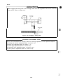
REVISION SHEET
REVISON
DATE ISSUED
CHANGE DOCUMENT
A
Feb. 21, 1992
1st issue
L
e,:.;-.,.
-v-
REV.-A
TABLE OF CONTENTS
CHAPTER 1.
CHAPTER 2.
CHAPTER 3.
CHAPTER 4.
CHAPTER 5.
CHAPTER 6.
APPENDIX
GENERAL DESCRIPTION
OPERATING PRINCIPLES
DISASSEMBLY AND ASSEMBLY
ADJUSTMENTS
TROUBLESHOOTING
MAINTENANCE
- vi –
REV
CHAPTER 1
GENERAL DESCRIPTION
1.1
FEATURES . . . . . . . . . . . . . . . . . . . . . . . . . . . . . . . . . . . . . . . . . . . . . . . . . . . . . . . . . . . . . . . . . . . . . . . . . . . . . . . . . . . . . . . . . . . . . . . . . 1-1
1.2
SPECIFICATIONS . . . . . . . . . . . . . . . . . . . . . . . . . . . . . . . . . . . . . . . . . . . . . . . . . . . . . . . . . . . . . . . . . . . . . . . . . . . . . . . . . . 1-3
.
1.2.1 Hardware Specifications . . . . . . . . . . . . . . . . . . . . . . . . . . . . . . . . . . . . . . . . . . . . . . . . . . . . . . . .. 1-3
1.2.2 Firmware Specifications . . . . . . . . . . . . . . . . . . . . . . . . . . . . . . . . . . . . . . . . . . . . . . . . . . . . . . . .. .1-9
1.3
INTERFACE Overflew....... . . . . . . . . . . . . . . . . . . . . . . . . . . . . . . . . . . . . . . . . . . . . . . . . . . . . . . . . . . . . . .. ..1-14
1.3.1 Parallel interface...... . . . . . . . . . . . . . . . . . . . . . . . . . . . . . . . . . . . . . . . . . . . . . . . . . . . . . . . .. .........1 -14
1.4
CONTROL PANEL . . . . . . . . . . . . . . . . . . . . . . . . . . . . . . . . . . . . . . . . . . . . . . . . . . . . . . . . . . . . . . . . . . . . . . . . . . . . . ....1
. . -16
1.5
DIP SWITCHES AND JUMPER SETTING ......................................1-18
1.5.1 DIP Switch Settings . . . . . . . . . . . . . . . . . . . . . . . . . . . . . . . . . . . . . . . . . . . . . . . . . . . . . . . . . . . . . . . .1-18
.
1.5.2 Jumper Setting . . . . . . . . . . . . . . . . . . . . . . . . . . . . . . . . . . . . . . . . . . . . . . . . . . . . . . . . . . . . . . . . . . . . . . . .1-19
...
1.6
OPERATING INSTRUCTIONS... . . . . . . . . . . . . . . . . . . . . . . . . . . . . . . . . . . . . . . . . . . . . . . . . . . . . . . . . .. 1-20
.
1.6.1
Self.Test...... . . . . . . . . . . . . . . . . . . . . . . . . . . . . . . . . . . . . . . . . . . . . . . . . . . . . . . . .. . . . . . . . . . . . . . . . . . . . . . . 1-20
1.6.2
Hexadecimal Dump Function . . . . . . . . . . . . . . . . . . . . . . . . . . . . . . . . . . . . . . . . . . . . . . . .. 1-20
1.6.3
Paper-out Detection and Forms Override Function . . . . . . . . 1-20
1.6.4
Error Conditions . . . . . . . . . . . . . . . . . . . . . . . . . . . . . . . . . . . . . . . . . . . . . . . . . . . . . . . . . . . . ..............1 -20
1.6.5
Buzzer Operation . . . . . . . . . . . . . . . . . . . . . . . . . . . . . . . . . . . . . . . . . . . . . . . . . . . . . . . . . . . . . . . . . . . . . 1-21
..
1.6.6
Printer initialization. . . . . . . . . . . . . . . . . . . . . . . . . . . . . . . . . . . . . . . . . . . . . . . . . . . . .. ...........1
..
-21
1.6.7
Default Values . . . . . . . . . . . . . . . . . . . . . . . . . . . . . . . . . . . . . . . . . . . . . . . . . . . . . . . . . . . . . . . . . . . .........1 -22
1.6.8
Sheet Loading and Sheet Ejection . . . . . . . . . . . . . . . . . . . . . . . . . . . . . . . . . . . . . . . 1-22
1.6.9
Tear-off Function . . . . . . . . . . . . . . . . . . . . . . . . . . . . . . . . . . . . . . . . . . . . . . . . . . . . . . . . . . . . . . . . . . . . . .. 1-23
.
1.6.10 Adjust Lever Operation . . . . . . . . . . . . . . . . . . . . . . . . . . . . . . . . . . . . . . . . . . . . . . . . . . . . . . . . . . . 1-23
1.6.11 Printhead Protection . . . . . . . . . . . . . . . . . . . . . . . . . . . . . . . . . . . . . . . . . . . . . . . . . . . . . . . . . .. ......1 -24
1.6.12 Ink Charge . . . . . . . . . . . . . . . . . . . . . . . . . . . . . . . . . . . . . . . . . . . . . . . . . . . . . . . . . . . . . . . . . . . . . . . . . . . . . . . .1-24
....
1.6.13 Ink End Detection . . . . . . . . . . . . . . . . . . . . . . . . . . . . . . . . . . . . . . . . . . . . . . . . . . . . . . . . . . . . . . . . 1-24
.....
1.6.14 Cover Open Detection . . . . . . . . . . . . . . . . . . . . . . . . . . . . . . . . . . . . . . . . . . . . . . . . . . . . . . . . . . . . . . 1-24
1.7
MAIN COMPONENTS . . . . . . . . . . . . . . . . . . . . . . . . . . . . . . . . . . . . . . . . . . . . . . . . . . . . . . . . . . . . . . . . . . . . . . . . . . . . 1-25
1.7.1 C076 MAIN Board (Main Control Circuit Board) ............l-26
1.7.2 Control Panel . . . . . . . . . . . . . . . . . . . . . . . . . . . . . . . . . . . . . . . . . . . . . . . . . . . . . . . . . . . . . . . . . . . . . . . . . ......1 -27
1.7.3 C076 PSB/PSE Board (Power Supply Circuit Board) ....l-27
1.7.4 Printer Mechanism (M.471 O/476 O).....................................l.28
1.7.5 Housing . . . . . . . . . . . . . . . . . . . . . . . . . . . . . . . . . . . . . . . . . . . . . . . . . . . . . . . . . . . . . . ......................1
.....
-28
I.i
REV.-A
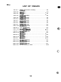
LIST OF FIGURES
Figure 1-1.
..
Exterior View of the SQ-1 170 . . . . . . . . . . . . . . . . . . . . . . . . . . . . . . . . . . . . . . . . . .1-2
Figure 1-2.
Nozzle Configuration . . . . . . . . . . . . . . . . . . . . . . . . . . . . . . . . . . . . . . . . . . . . . . . . . . .. ......1-3
....
Figure 1-3.
...
Release Lever Positions . . . . . . . . . . . . . . . . . . . . . . . . . . . . . . . . . . . . . . . . . . . . . . . . . . . . . 1-4
....
Figure 14. Label Size . . . . . . . . . . . . . . . . . . . . . . . . . . . . . . . . . . . . . . . . . . . . . . . . . . . . . . . . . . . . . . . . . . . . . . . . . . . . . . .1-5
Figure 1-5.
..
Printable Area for Cut Sheets . . . . . . . . . . . . . . . . . . . . . . . . . . . . . . . . . . . . . . . . . .1-6
Figure 1-6.
.
Printable Area for Continuous Papers . . . . . . . . . . . . . . . . . . . . . . . . . . . . 1-6
Figure 1-7.
..
Printer Operating Environment . . . . . . . . . . . . . . . . . . . . . . . . . . . . . . . . . . . . . . . . 1-8
Figure 1-8.
...
Character Matrix . . . . . . . . . . . . . . . . . . . . . . . . . . . . . . . . . . . . . . . . . . . . . . . . . . . . . . . . . . . . . . . . . .1-13
Figure 1-9.
Data Transmission Timing . . . . . . . . . . . . . . . . . . . . . . . . . . . . . . . . . . . . . . . . . . . . . . . . . . 1-14
....
Figure 1-10. Control Panel . . . . . . . . . . . . . . . . . . . . . . . . . . . . . . . . . . . . . . . . . . . . . . . . . . . . . . . . . . . . . . . . . . . . . . . . 1-16
....
Figure 1-11. Lever Positions . . . . . . . . . . . . . . . . . . . . . . . . . . . . . . . . . . . . . . . . . . . . . . . . . . . . . . . . . . . . . . . . . . . . . 1-23
..
Figure 1-12. SQ-1 170 Component Layout . . . . . . . . . . . . . . . . . . . . . . . . . . . . . . . . . . . . . . . . . . . .1-25
...
Figure 1-13. C076 MAIN Board . . . . . . . . . . . . . . . . . . . . . . . . . . . . . . . . . . . . . . . . . . . . . . . . . . . . . . . . . . . . . . .1-26
....
Figure 1-14. Control Panel . . . . . . . . . . . . . . . . . . . . . . . . . . . . . . . . . . . . . . . . . . . . . . . . . . . . . . . . . . . . . . . . . . . . . . 1-27
Figure 1-15. C076 PSB/PSE Board ...........................................................l -27
Figure 1-16. Model-4710/4760 Printer Mechanism . . . . . . . . . . . . . . . . . . . . . . . . . . . . 1-28
.....
Figure 1-17. Housing . . . . . . . . . . . . . . . . . . . . . . . . . . . . . . . . . . . . . . . . . . . . . . . . . . . . . . . . . . . . . . . . . . . . . . . . . . . . . . . . . . 1-28
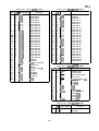
LIST OF TABLES
Table 1-1.
...
Interface Options . . . . . . . . . . . . . . . . . . . . . . . . . . . . . . . . . . . . . . . . . . . . . . . . . . . . . . . . . . . . . . . . . . 1-1
Table 1-2.
Optional Units . . . . . . . . . . . . . . . . . . . . . . . . . . . . . . . . . . . . . . . . . . . . . . . . . . . . . . . . . . . . . . . . . . . . . . . . . 1-2
..
Table 1-3.
Specifications for Cut Sheets . . . . . . . . . . . . . . . . . . . . . . . . . . . . . . . . . . . . . . . . . . . . . . . 1-4
Table 14.
. -4
Specifications for Continuous Papers . . . . . . . . . . . . . . . . . . . . . . . . . . . . . . 1
Table 1-5.
....
Envelopes . . . . . . . . . . . . . . . . . . . . . . . . . . . . . . . . . . . . . . . . . . . . . . . . . . . . . . . . . . . . . . . . . . . . . . . . . . . . . . . . .1-5
Table 1-6.
..
Labels Specifications . . . . . . . . . . . . . . . . . . . . . . . . . . . . . . . . . . . . . . . . . . . . . . . . . . . . . . . . . . . . .1-5
Table 1-7.
..
Built in Bit-map Fonts . . . . . . . . . . . . . . . . . . . . . . . . . . . . . . . . . . . . . . . . . . . . . . . . . . . . . . . . . . . .1-9
Table 1-8.
.
Printing (Text Mode) . . . . . . . . . . . . . . . . . . . . ... . . . . . . . . . . . . . . . . . . . . . . . . . . . . . . . . . . . . .1-1o
Table 1-9.
...
Printing (Bit Image Mode) . . . . . . . . . . . . . . . . . . . . . . . . . . . . . . . . . . . . . . . . . . . . . . . . . 1-11
Table 1-10.
.
Character Matrix and Character Size . . . . . . . . . . . . . . . . . . . . . . . . . . . . .1-12
Table 1-1 f.
Connector Pin Assignments and Signal Functions . . . . . 1-14
Table 1-12.
Settings for DIP Switch 1 (sw1)................................-.....1-18
Table 1-13.
Settings for DIP Switch 2 (SW2).......... . . . . . . . . . . . . . . . . . . . . . . . . . ..1-18
.
Table 1-14.
International Character Set Selection . . . . . . . . . . . . . . . . . . . . . . . . . . . . . 1-19
Table 1-15.
....
Page Length . . . . . . . . . . . . . . . . . . . . . . . . . . . . . . . . . . . . . . . . . . . . . . . . . . . . . . . . . . . . . . . . . . . . . . . . . .1-19
Table 1-16.
....
Lever Positions . . . . . . . . . . . . . . . . . . . . . . . . . . . . . . . . . . . . . . . . . . . . . . . . . . . . . . . . . . . . . . . . . . . . . 1-23
Iii
...
,..
kJ
REV.-A
1.1 FEATURES
The SQ-870/l 170 is a high speed 48-nozzle ink jet printer which provides advanced paper handling
that is upper compatible with the TSQ-4800. The printer’s main features are as follows:
● Use of ESC/P 2 control codes
Ability to print multi-point fonts
Ability to receive and print raster graphic images
Compatibility with the LQ\SQ series available on the market
● Printing speeds:
660 cps (draft, 12 cpi)
550 cps (draft, 10 cpi)
2 4 0 cps (LQ, 12 cpi)
2 0 0 cps (LQ, 10 cpi)
● Optional interface card
● Clear, easy-to-read printing with standard EPSON fonts
● Multiple fonts resident in the printer
2 scalable fonts (Roman, Saris Serif)
8 LQ bit-map fonts (Roman, Saris Serif, Courier, Prestige, Script, Script C, Orator, Orator-S)
1 draft bit-map font
●
●
●
●
Control panel switch selection of fonts, pitch, and cut-sheet feeder (CSF) bin
Optional tractor unit that can make up push-pull tractor
Easy handling of cut sheets with the optional cut-sheet feeder
Continuous Paper
Two ways to insert continuous paper (front/rear path)
Backout & loading
Continuous paper can be used without removing CSF
Standard tractor unit can be attached in two positions (front/rear)
● Cut Sheet
Two ways to insert cut sheets (front/top)
Auto loading
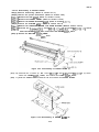
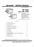
The SQ-870/l 170 is equipped with the standard EPSON 8-bit parallel interface and various interface
options ensure compatibility with a wide variety of computers. Table 1-1 lists the interface options, Table
1-2 lists the optional units available for the SQ-870/l 170, and Figure 1-1 shows an exterior view of
the SQ-870/l 170
Table 1-1. Interface Options
Descriptions
Model
C82305
Serial interface card (inch screw)
C82306
Serial interface card (mini screw)
C82307
32KB serial interface card (inch screw)
C82308
32KB serial interface card (mini screw)
C82310
32KB parallel interface card
C82313
32KB IEEE-488 interface card
NOTE: Refer to the “Optional Interface Technical Manual” for details.
1-1
REV.-A
Table 1-2. Optional Units
1
Descriptions
Model
I C80647
/ Single-bin cut-sheet feeder (80 columns]
C80648
Single-bin cut-sheet feeder (136 columns)
C80637
Second bin hopper (80 columns)
IC80640 I S e c o n d binhopper(136 c o l u m n s )
C80023
Tractor unit (80 columns)
C80024
Tractor unit (136 columns)
SO2OO1O
Ink cartridge
I
I
I
J
Figure 1-1. Exterior View of the S(2-870/1 170
0
.,,?5
e.
1-2
REV.-A
1.2 SPECIFICATIONS
This section provides specifications for the SQ-870/l 170 printer.
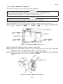
1.2.1
Hardware Specifications
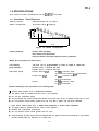
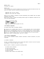
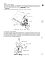
Printing method
On-demand type ink jet system
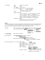
Nozzle configuration
48 nozzles (48 X 1 diagonal)
1
‘o
a
m
~
h
*i
‘g
s
Al
\-
~1
A2
‘2 A
3
~
(7.125°)
3
*
1/45”
47/45”
●
h
Figure 1-2. Nozzle Configuration
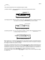
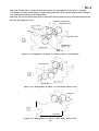
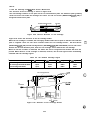
Feeding methods
Friction feed (front/top)
Push tractor feed (front/rear)
Push-pull tractor feed (with optional tractor) (front/rear)
NOTE: Do not perform pull tractor feed.
Line spacing
1/6 inch, 1/8, or programmable in units of 1/180 or 1/360 inch
Paper insertion
Friction feed — Front or top side
Tractor feed — Front or rear side
Paper-feed speed
Friction without CSF
45 msec (1/6-inch feed)
4.5 inches per second (ips) (continuous)
Friction with CSF
49 msec (1/6-inch feed)
4.0 ips (continuous)
Tractor
45 msec (1/6-inch feed)
4.5 ips (continuous)
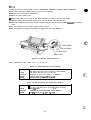
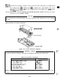
NOTE: Following are the precautions for handling paper.
1
Friction feed (release lever in FRICTION POSITION).
● The paper must be loaded from the front or top entrance.
● Do not use continuous paper.
● Do not perform any reverse paper feeds within the top 8.5 mm (.34 in.) or bottom 22 mm (.87 in.) area.
●
Do not perform reverse feeds greater than 1/6 inch after a paper end has been detected.
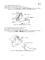
2
Push tractor feed (release lever in REAR PUSH POSITION or FRONT PUSH POSITION).
● The paper must be loaded from the front or rear entrance.
● Release the friction-feed mechanism.
●
Do not perform reverse feeds greater than 1/6 inch.
● Since accuracy of paper feed cannot be assured after the paper end has been detected, do not perform
reverse feeding after the detection of a paper end.
1-3
REV.-A
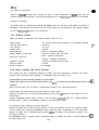
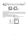
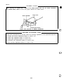
3. Push-pull tractor feed (release lever in REAR PUSH POSITION or FRONT PUSH POSITION).
● The paper must be loaded from the front or rear entrance.
● Release the friction-feed mechanism.
● Attach the pull tractor unit.
O Ensure that there is no slack in the paper between the platen and the pull tractor.
● Precisely adjust the horizontal position of the pull tractor and push tractor.
● Paper for multiple copies must be spot pasted on both side of the perforation betvveen the tractor
holes.
● Do not perform reverse feeds greater than 1/6 inch.
● Do not perform a reverse feed after the paper end has been detected.
Rear Push Position
\
Release Position
Figure 1-3. Release Lever Positions
Paper specifications See tables 1-3, 1-4, 1-5, and 1-6
Table 1-3. Specifications for Cut Sheets
Width
182 mrn to 257 mm (7.2 in. to 10.1 in.) (80 columns)
Length
Thickness
182 mm to 420 mm (7.2 in. to 16.5 in.) (136 columns)
182 mm to 364 mm (7.2 in. to 14.3 in.)
0.065 mm to 0.10 mm (0.0025 in. to 0.0039 in.)
14 lb to 22 lb (52.3 g/m2 to 82 g/m2)
Weight
Quality
Standard paper (photocopier paper, etc.)
Table 1-4. Specifications for Continuous Papers
Width
I 101 mm to 254 mm (4.0 in. to 10.0 in.) (80 columns)
I 101 mm to 406 mm (4.0 in. to 16.0 in.) (136 columns]
Quality
Thickness
Weight
Stan jard paper
0.065 mm to 0.10 mm (0.0025 in. to 0.0039 in.)
14 lb to 22 lb (52.3 g/m2 to 82 g/m2)
.:
i..)
f-’
1-4
REV.-A
Table 1-5. EnveIo~es
Size
Thickness
[
Weight
Quality
No. 6 166 mm X 92 mm (6.5 in. X 3.625 in.)
No. 10240 mm X 104 mm (9.5 in. X 4.125 in.)
0.16 mm to 0.52 mm (0.0063 in. to 0.0197 in.)
Differences in thickness within the printing area must be less
than 0.25 mm (0.0098 in.)
12 lb to 24 lb (45 g/m2 to 91 g/m2)
Bond paper, standard paper, airmail
NOTES: ● Printing on envelopes is available only at normal temperatures and only using top
insertion.
● Keep the longer side of the envelope horizontal during insertion.
● Place the left edge of a No. 6 envelope at the sheet guide setting mark.
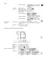
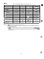
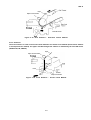
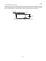
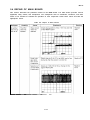
Table 1-6. Labels Specifications
Label size
Copies
Thickness
2.5 in. X 0.94 in.
4.0 in. X 0.94 in.
4.0 in. X 1.44 in.
These three kinds of labels are recommended.
0.22 mm (0.0079 in.) maximum
NOTES: ● Printing on labels is available only at normal temperatures.
● Labels must be of the continuous type.
● Examples of labels AVERY CONTINUOUS FORM LABELS
AVERY MINI-LINE LABELS
F;;::~?nch)r’
‘
23.8mm
(0.94inch)
L
36.5mm
(1 .44inch)
Figure 1-4 Label Size
1-5
REV.-A
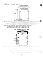
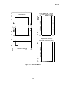
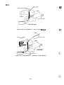
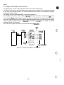
Printable area
See figures 1-5 and 1-6
182-257mm ~.2-10.lind?) : 60cdm
=
k~
13.5rnm (0.53-inti) or more
0
q.
● 1: 80 columns: 3.0 mm (0.12 in.) or more when the width of paper is less than 229 mm (9 in.). ~~•
13 mm (0.51 in.) or more when the width of paper is 257 mm (10.1 in.).
136 columns: 3.0 mm (O. 12 in.) or more when the width of paper is less than 364 mm (1 4.3 in.)
25 mm (0.98 in.) or more when the width of paper is 420 mm (16.5 in.).
NOTE: The paper feed accuracy can not be assured within the following area.
Front insertion: 47 mm (1 .85 in.) from the bottom edge of paper.
Rear insertion: 26 mm (1 .02 in.) from the bottom edge of paper.
Figure 1-5. Printable Area for Cut Sheets
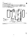
101 -254mm (4-10inch) : 60 columns
b
101 -406mm [4-16inch) : 136 columns
*
Printable area
●1
●
-
max. 203mm (6. Oinch) : 60 columns
345mm (13.6inch): 136 columns
I
0
0
0
0
0
0
Printable 0
0
area 0
0
0
XYZ:
0o ABC
- 1
L
0
o
0
9mm or more 0
0
0
(0.35inch)
0
0
r - - - - - - - - - - - - - - - - o
?
0
9mm or more :
0
(0.35inch) o
0
:
0
XYzo
o ABC
0
o
1
-fo
Printable :
0
4-
c., .
>$’
r
● 1: 80 columns:
13 mm (0.51 in.) or more when the 101 mm (4.0 in.) to 241 mm (9.5 in.) width paper
is used.
26 mm (1 .02 in.) or more when the 254 mm (1 O in.) width paper is used.
136 columns: 13 mm (0.51 in.) or more when the “101 mm (4.0 in.) to 377.8 mm (1 4.87 in.) width
paper is used.
15 mm (0.59 in.) or more when the 381 mm (15 in.) to 406 mm (16 in.) width paper
is used.
@’
Figure 1-6. Printable Area for Continuous Papers
1-6
REV.-A
Ink cartridge
Type:
Exclusive ink cartridge
Color:
Black
Ink capacity:
105 to 115 cc
Print capacity (depending on the cleaning operation):
Draft:
6 million characters
Letter Quality: 3 million characters
Ink life:
Storage
2 years from production date
temperature:
–30 to 40 degrees C (–22 to 104 degrees F) -Storage
(within a month at 40 degrees C (104 degrees F))
–30 to 60 degrees C (–22 to 140 degrees F) -Transit
(within a month at 40 degrees C (104 degrees F ) )
(within 120 hours at 60 degrees C (140 degrees F))
Dimension of cartridge:
24.8 mm (W) X 138 mm (D) X 99.3 mm (H)
(0.98 inch X 5.43 inch X 3.91 inch)
NOTES:
● Ink will be frozen under –7 degrees C (19 degrees F) environment, however it will be usable after placing
it at room temperature. (It will take approx2.5 hours until melting at 25 degrees C (77 degrees F).)
● Do not use the ink cartridge which has been stored longer than the ink life.
Reliability
Mean cycles between failures (MCBF) 5 million lines (excluding printhead)
Mean time between failures (MTBF)
4000 power on hours (POH) (25%
duty)(SQ-870)
6000 power on hours (POH) (25’%.
duty)(SQ-1 170)
Life of printhead
4000 million dots/nozzle
Safety approvals
Safety standardsULl 950 with D3 (U. Aversion)
CSA22.2#220
EN 60950 (TUV) (European version)
Radio frequency interference (RFI) FCC class B (U. Aversion)
VDE0871
(self-certification)
(European
version)
Electrical specifications 120 V version Rated voltage
120 VAC
Input voltage range
103.5 to 132 VAC
Rated frequency range
50 to 60 Hz
Input frequency range
49.5 to 60.5 Hz
Rated current
0.6 A
Power consumption
Approx. 30 W (SQ-870)
Approx. 30 W (SQ-1 1 7 0 )
(during a self-test in draft mode, 10 cpi)
Insulation resistance
10 Megohms minimum (at 500 VDC
between AC line and chassis).
1-7
REV.-A
1 0 0 0 VAC rms 1 minute or 1200
Dielectric strength
VAC rms 1 second (between AC line
and chassis)
220 to 240 VAC
Rated voltage
220/240
version
Input voltage range
198 to 264 VAC
Rated frequency range
50 to 60 Hz
Input frequency range
49.5 to 60.5 Hz
Rated current
0.4 A
Power consumption
Approx. 30 W (SQ-870)
Approx. 30 W (SQ-1 170)
(during a self-test in draft mode, 10 cpi)
Insulation resistance
10 Megohms minimum (at 500 VDC
between AC line and chassis).
Dielectric
Strength
1 2 5 0 VAC rms 1 minute or 1500
VAC rms 1 second (between AC line
and chassis)
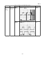
Environmental
10 to 35 degrees C (50 to 95 degrees F) – operating
Temperature
–30 to 60 degrees C (–22 to 140 degrees F) -in shipment
conditions
container
Humidity
20 to 80 % RH - operating
5 to 85 % RH - storage
NOTE: Figure 1-5 shows the operating environment.
I
Temperature (“c)
Figure
1-7. Printer Operating Environment
Resistance to
1 G, within 1 ms - operating
shock
2 G, within 1 ms - storage
Resistance to
0.25 G, 55 Hz, max - operating
vibration
0.50 G, 55 Hz, max - storage
Physical specifications Weight
9.5 Kg, approx. (2 1.0 pounds, approx.) (SQ-870)
12.2 Kg, approx. (27.0 pounds, approx.) (SQ-1 170)
Dimensions
462 mm (width) X 325 mm (depth) X 205 mm (height)
1 8 . 2 in(width)
X 12.8 in(depth) X 8.1 in(height) (SQ-870)
657 mm (width) X 325 mm (depth) X 205 mm (height)
2 5 . 9 in(width) X 12.8 in(depth) X 8.1 in(height) (SQ-1 1 7 0 )
1-8
.,.-:. ,
., ”’-,,,
o
REV.-A
1.2.2 Firmware Specifications
Control code
ES C/PTM
level 2 (EPSON standard code for printers)
Printing direction
Bi-directional with logic seeking (text printing)
Uni-directional (bit-image printing)
Input data buffer
16KB (Standard)
128KB (factory option)
Character code
Character tables
8 bits
Italic character table, PC 437, PC 850, PC 860, PC 863, PC 865 (PC indicates
character table for personal computer)
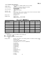
Fonts and pitches
Bit-map fonts
See table 1-7
Scalable fonts
EPSON Roman
8 pt to 32 pt
EPSON Saris-serif
8 pt to 32 pt
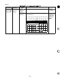
Table 1-7. Built in Bit-ma~ Fonts
I Family
I
No.
I
10
CPI I
12
CPI I
15
CPI I
Proportional
I
EPSON Roman
o
0
0
0
0
EPSON Saris-serif
1
0
0
0
0
EPSON Courier
2
0
0
0
●
EPSON Prestige
3
0
0
0
●
EPSON Script
4
0
0
0
●
EPSON Script-C
9
0
0
0
.
EPSON Orator
7
0
.
x
.
EPSON Orator-S
8
0
“
x
●
EPSON DRAFT
..-
0
0
0
xx
0-- R e s i d e n t
, -Desired pitch is made by software using selected font
x --
print Roman 15 CPI
xx -- Print LQ proportional font selected by ESC k
Printing modes
Selection and mixture of the following modes are allowed, excluding 15 cpi
condensed mode:
O Print quality (draft/letter quality)
O Character pitch (1 O, 12, 15, or proportional)
O Condensed
O Double-width
O Double-height
O Emphasized
O Double-strike
O Italic
O Underlined
O Double-underlined
O Overscore
O Strike-through
O Outline
O Shadow
1-9
REV.-A
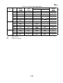
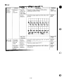
Printing speed
See Tables 1-8 and 1-9.
Printing columns
See Table 1-8.
Character matrix
See Table 1-10.
Character size
See Table 1-10.
Table 1-8. Printing (Text Mode)
Print
Con-
Empha-
Pitch
densed
sized
Printable
Columns
Double
width
80
10
12
15
COi.
136
Col.
Charactar
Pitch
(cpi)
Printing Speed
(Cps)
Draft
LQ
0
0
0
80
136
10
550
200
0
0
1
40
68
5
275
100
0
1
0
80
136
10
400
200
,
0
1
1
40
68
5
200
100
1
x
o
137
233
17.1
684
342
1
x
1
68
116
8.5
342
171
0
0
0
96
163
12
660
240
0
0
1
48
81
6
330
120
0
1
0
96
163
12
480
240
0
1
1
48
81
6
240
120
1
x
o
160
272
20
800
400
1
x
1
80
136
10
400
200
0
0
0
120
204
15
825
300
0
0
1
60
102
7.5
412
150
0
1
0
120
204
15
600
300
0
1
1
60
102
7.5
300
150
1
x
x
CPI:
characters per inch
CPS:
characters per second
LQ:
letter quality
e;,?
Cannot be condensed
,<..
(’J
1-1o
~
REV.-A
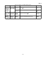
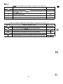
Table 1-9. Printing (Bit Image Mode)
Pins
m
Density
(DPI)
Adjacent
Dot
Printing
80 Columns
136 Columns
Printing
Speed
(IPS)
8
0
60
Yes
480
816
55
1
120
Yes
960
1632
20
2
120
No
960
1632
20
3
240
No
1920
3264
20
4
80
Yes
640
1088
20
6
90
Yes
720
1224
55
32
6 0
Yes
480
816
55
33
120
Yes
960
1632
20
38
90
Yes
720
1224
55
39
180
Yes
1440
2448
20
40
360
No
2880
4896
20
71
180
Yes
1440
2448
20
72
360
No
2880
4896
20
73
360
Yes
2880
4896
20
Dot
24
48
DPI:
dots per inch
IPS:
inches per second
256 X n2 + nl
1-11
REV.-A
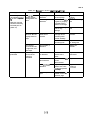
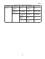
Table 1-10. Character Matrix and Character Size
Printing Mode
,
Face Matrix
HOD
Character Size
Unit ESC sp
;Draft, 10 pitch
15 x 44
180
2.1 x 3.1
120
Draft, 12 pitch
13 x 44
180
1.s
3.1
120
Draft, 15 pitch
11 X 32
180
1.6 X 2.3
120
Draft, 17 pitch
15 x 44
360
1.1 x 3.1
120
Draft, 20 pitch
13 x 44
360
0.9 x 3.1
120
LQ, 10 pitch
31 x 22
360
2.2 x 3.1
180
LQ, 12 pitch
27 X 22
360
1.9 x 3.1
180
LQ, 15 pitch
22 X 16
360
1.6 X 2.3
180
LQ, 17 pitch
16 X 44
360
1.1 x 3.1
180
LQ, 20 pitch
14 x 44
360
1.0 x 3.1
180
LQ, proportional
Max. 37 X 44
Min. 18 X 44
360
360
2.6 X 3.1
1.() x 3.1
180
LQ, proportional,
super/subscript
Max. 28 X 32
Min. 12 X 32
360
360
1.8 X 2.3
0.7 X 2.3
180
NOTES:
●
●
X
*
@
HDD is horizontal dot density in dots per inch.
Face matrix and character size indicate the maximum size of a character. This value is
dependent on paper, etc.
●
Unit ESC sp (which also can be sent as unit, followed by the character string CHR$(&h20)),
indicates the minimum length to be added to the right of the character specified in the ESC
SP
control code.
..; ,
@
1-12
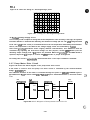
REV.-A
(Normal character)
1~
2
Ascender area
3
17
18
4
5
1:
.
.
.
6
7
R
k
F
.
k
/y/
//
s
/ T /
/s/
.
.
:
c
E
39
.
.
.
45
46
47
48
:
c
E
40
41
.
.
(a2)
(aO)
46
Descender area
(Super-script character)
From dot No. 33 to 48 are not
used while superscript printing.
—
47
L
48
L
(Sub-script character)
From dot No. 1 to 16 are not
I while subscri~t
,.txinting.
—
;
3
4
.
.
L
Character width (CW)
4
.
.
29
30
31
32
Figure 1-8. Character Matrix
1-13
REV.-A
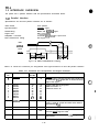
1.3 INTERFACE OVERVIEW
The printer has a parallel interface with the specifications described below.
1.3.1 Parallel Interface
Specifications for the 8-bit parallel interface are as follows:
Data format
8-bit parallel
Synchronization
STROBE signal
Handshaking
BUSY and ACKNLG signal
Signal level
ITL-compatible
Adaptable
57-30360 (Amphenol)
connector
Data transmission timing
or equivalent
See Figure 1-9.
BUSY
It
,/
4
[
//
ACKNLG
DATA
STROBE
o.5#s
o.5/.ls
o.5/ls
511s
5ps
min.
min.
min.
WP
typ. ‘
Figure
1-9. Data Transmission Timing
Table 1-11 shows the connector pin assignments and signal functions of the 8-bit parallel interface.
Table 1-11. Connector Pin Assignments and Signal Functions
Pin
No.
1
Signal Name
STROBE
Return
Pin No.
Dir.
Functional Description
19
IN
STROBE pulse to read the input data. Pulse width must
be more than 0.5Ks. Input data is latched at falling
edge of this signal.
2
3
4
5
6
7
8
9
DATA 1
DATA 2
DATA 3
DATA 4
DATA 5
DATA 6
DATA 7
DATA 8
20
21
22
23
24
25
26
27
IN
IN
IN
IN
IN
IN
IN
IN
10
ACKNLG
28
OUT
This pulse indicates data has been received and the
printer is ready to accept more data. Pulse width is
approximately 1 Ips.
11
BUSY
29
OUT
HIGH indicates the printer cannot accept more data.
12
PE
30
OUT
HIGH indicates paper out. This signal is effective only
when the ERROR signal is LOW,
13
SLCT
OUT
Always HIGH output (Pulled up to +5V through a 3.3K
ohm resistor.)
0
,-.’ ,
. .
Parallel input data to the printer.
HIGH level means “ 1“.
LOW level means “O”.
1
1-14
Table 1-11. Connector Pin Assignments and Signal Functions (Cont.)
Pin
No.
Signal Name
14
AUTOFEED-XT
Return
Pin No.
Dir.
--
IN
Functional Description
If LOW when the printer is initialized, the printer
automatically performs a line feed upon input of the
CR code (Auto LF).
Not used.
15
16
GND
17
Chassis GND
..
.-
Ground for twisted-pair grounding.
--
Chassis ground level of printer.
Not used.
18
19 to 30
GND
31
I NIT
Ground for twisted-pair grounding.
16
IN
Pulse (width: 50ws, min., active LOW) input for printer
initialization.
32
ERROR
33
GND
OUT
--
..
Ground for twisted-pair grounding.
Not used.
34
35
36
LOW indicates an error has occurred in the printer.
OUT
SLCT-IN
--
Always HIGH. (Pulled up to +5V through 3.3K ohm
resistor.)
If LOW when the printer is initialized, DC l/DC3
control is disabled.
IN
NOTES: 1. “Dir.” indicates the direction of the signal flow as viewed from the printer.
2. “Return Pin No.” denotes a twisted-pair return line.
3. The cable used must be shielded to prevent noise.
4. All interface conditions are based on TTL levels. Both the rise and fall times of all signals
must be less than 0.2Ks.
5. The AUTOFEED-XT
signal can be set to LOW by DIP switch 2-4.
6. The SELECT-IN signal can be set to LOW by jumper 1.
7. Printing tests, including those of the interface circuits, can be performed without using
external equipment by setting DATA 1 -DATA 8 pins to the STROBE signal.
1-15
REV.-A
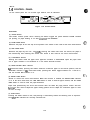
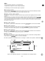
1.4
CONTROL PANEL
On the control panel are: 10 non-lock type buttons, and 24 indicators.
k
——
I
Lom I -!. I
0 111—
Figure 1-10. Control Panel
BUTTONS
(1) PAUSE Button
This button controls printer action. Pressing the button toggles the printer between PAUSE condition
(no printing, no paper feeding, or no data acception)
and RUNNING.
(2) FORM FEED Button
Advances the paper to the next top of from position. This switch is also used for the micro feed function.
(3) LINE FEED Button
Advances the paper by one line ( 1/6 inch)By pressing this switch more than 0.5 second, the paper is
fed continuously until releasing this switch. This switch is also used for the micro feed function.
(4) LOAD/EJECT Button
Pushing this switch loads the paper when paper-out condition is detectedAnd ejects the paper when
out of paper condition is not detected as in the Forms Override function.
(5) TEAR-OFF/BIN l/BIN 2 Button
In tractor-feed mode, pressing this button advances continuous paper to the tear-off position, and the
TEAR-OFF indicator is Iitln friction-feed mode, pressing this button toggles between bin 1 and bin 2,
.c“~.
and the selected BIN indicator is lit.
.’)
(6) MICRO FEED Button
Selects or cancels the micro feed function. When this function is enabled, the MICRO FEED indicator
is lit. In the micro feed mode, the LINE FEED button is used to feed the paper forward, and the FORM
FEED button is used to feed the paper backward.
Paper feed performed by this micro feed function does not affect the page position control. And this
func!ion
is also used to adjust the paper loading position and to adjust the continuous paper to meet
the tear off edge.
(7) FONT Button
Pressing this button selects a font, and pressing it continuously selects the following ones in sequence.
The ‘ONT LED indicates the currently selected font.
1-16
REV.-A
(8) PITCH Button
Pushing this switch once selects the character pitch. And holding this button down selects the following
ones in sequence. PITCH indicators indicate the currently selected character pitch.
(9) RESET Button
Holding this button down more than 0.45 second, the input data buffer is cleared and the printer
initialized by software as ESC Cl?.
(10) CLEANING Button
Holding this button down more than 0.5 second, the print head cleaning is performed. This button is
only effective in the PAUSE condition. The CLEANING button is located inside the DIP switch cover.
INDICATORS
(1) POWER (green)
Lit when the printer’s power switch is on, and AC power is supplied.
(2) PAUSE (orange)
Lit when the printer is in PAUSE mode (no printing, no paper feed, or no data accepting).
(3) DATA (orange)
Lit when the printer has received data from the host machine.
(4) PAPER-OUT (red)
Lit when the paper-out detector detects no paper. Refer to Section 1.6.3, Paper-out Detection and Forms
Override Function.
(5) INK END (red)
Lit when the printer detects the ink empty condition.
(6) MICRO FEED (orange)
Lit when the micro feed function is enabled.
(7) TEAR-OFF (orange)
Lit when the sheet is advanced to the tear-off position.
(8) BIN 1 (green)
Lit when bin 1 is selected.
(9) BIN 2 (green)
Lit when bin 2 is selected.
(1 O) FONT (green) --Draft, Courier, Roman, Saris Serif, Prestige, Script, Script C, Orator, Orator-S
These indicators show the currently selected font.
(1 1) PITCH (green) --10 CPI, 12 CPI, 15 CPI, 17 CPI, 20 CPI, PS
These indicators show the currently selected pitch.
1-17
REV.-A
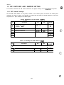
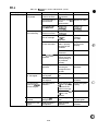
1.5 DIP SWITCHES AND JUMPER SETTING
This section describes the DIP switch selections and jumper setting for the SQ-870/l 170 printer.
1.5.1 DIP Switch Settings
The two DIP switch banks for the printer, located on the control panel, are used to set various print
conditions as shown in tables 1-12 through 1-15. (Note that the status of the DIP switches is read only
at power on or upon receipt of the INIT signal.)
Table 1.12. Settings for DIP Switch 1 (SW1)
Description
No.
ON
Factory
OFF
Setting
1
2
3
International
character set and PC
selection
ON
ON
ON
4
Character table selection
Graphic
Italic
OFF
5
Graphic print direction
Unidir.
Bidir.
OFF
6
Not Used
See
Table 1-14
OFF
7
OFF
8
OFF
Table 1-13. Settings for DIP Switch 2 (SW2)
No.
1
2
Description
I
ON
Page length of continuous paper
3
I
1 inch skip for continuous paper
[
OFF
ON
!
4
I
See Table 1-15
I
1
~ Auto LF
Factory
Setting
OFF
I
ON
OFF
OFF
I
OFF
I
OFF
I
,
OFF
=.
@
1-18
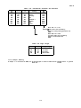
REV.-A
Table 1-14. international Character Set Selection
1-1
1-2
1-3
Pc
ON
ON
ON
ON
OFF
OFF
OFF
OFF
ON
ON
OFF
OFF
ON
ON
OFF
ON
OFF
ON
OFF
ON
OFF
ON
Us.
France
Germany
U.K.
Denmark 1
Sweden
Italy
437
850
860
863
865
(437)
(437)
OFF
OFF
Spain 1
(437)
Country
L
When SW 1-4 is ON,
~ If italic table was selected by
ESC t O, country setting becomes U.S.
When SW 1-4 is OFF,
if graphic table was selected by
ESC t 1, PC becomes 437.
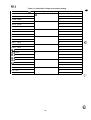
Table 1-15. Page Length
2-1
2-2
OFF
ON
OFF
ON
OFF
OFF
ON
ON
Page Length
11 inches
12 inches
8.5 inches
70/6 inches
1.5.2 Jumper Setting
If Jumper 1 is connected to GND, the SLCT-IN signal is fixed to LOW and DC l/DC3 control is ignored.
1-19
REV.-A
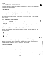
1.6 OPERATING INSTRUCTIONS
*
This section describes the self-test and hexadecimal dump functions as well as the error states, printer
initialization, and buzzer operation.
1.6.1 Self-Test
To run the self-test using draft mode, turn the printer on while pressing the LINE FEED button. To run
the self-test using the letter quality (LO) mode, turn the printer on while pressing the FORM FEED button.
You can stop or start self-test printing by pressing the PAUSE button. When you are satisfied with the
self-test, stop the printing by pressing the PAUSE button and turn the printer off.
The firmware revision number is printed on the first line of the self-test, followed by the current DIP
switch settings.
1.6.2 Hexadecimal Dump Function
To put the printer in hexdump mode, power it on while pressing both the LINE FEED and FORM FEED
buttons.
o
“i” ,,
In hexdump mode, the printer prints out the hexadecimal representation of the input data, along with
the corresponding ASCII characters. This function is useful for checking the data the printer has received
from the host.
If input data is a control code rather than a character code, a period (.) is printed in the ASCII column.
1.6.3 Paper-out Detection and Forms Override Function
When the paper-out detector detects a paper-out condition, the printer enters the PAUSE mode with
the following status.
PAPER OUT indicator lit
BUSY signal becomes HIGH
I
ERROR signal becomes LOW
PE signal becomes HIGH
c..
.,
.“..
In the PAUSE mode, you can perform the “Forms Override” function by pressing the PAUSE button,
or continue the printing operation by pressing the PAUSE button after loading new paper.
In the forms override function, the printer ignores the paper-out condition temporarily and prints
additional lines beyond the bottom line specified for the page. Once the “Forms Override” function is
performed, the paper-out detection will not be enabled until paper is loaded.
1.6.4 Error Conditions
If the following conditions are detected, the printer recognizes them as errors and enters the error mode.
● Paper-out
Paper-out is detected after performing paper loading operation.
. Ink end
Ink end condition is detected. Perform 200 lines of printing or remove the ink cartridge.
1-20
‘) :
REV.-A
● Cover open
The printer lid is opened.
● Fatal errors
In the following cases, the printer recognizes them as fatal errors and enters the fatal error mode. The
fatal error condition cannot be recovered until turning the power off.
● Carriage does not move correctly
● Control circuit cannot work correctly
When the error condition is detected, the printer automatically enters ‘PAUSE’ mode and outputs
appropriate interface signal.
When parallel interface is selected, the following interface signals are outputted to indicate the error
and to stop data transmission.
● BUSY signal becomes HIGH
● ERROR signal becomes LOW
● Output no ACKNLG pulse
● PE signal becomes HIGH (only paper out error)
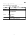
1.6.5 Buzzer Operation
The buzzer sounds under the following conditions:
● A paper-out error is detected (beeps 3 times for 0.1 second respectively, with 0.1 second intervals).
● Ink end error is detected (beeps 5 times for 0.1 second respectively, with 0.1 second intervals).
● Cover open error is detected (beeps 5 times for 0.1 second respectively, with 0.1 second intervals).
● Fatal error is detected (beeps 5 times for 0.5 second respectively, with 0.5 second intervals).
● When panel setting is accepted (beeps 1 time for 0.1 second).
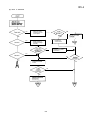
1.6.6 Printer Initialization
There are three initialization methods: hardware initialization, software initialization, and panel
initialization.
(1) Hardware initialization
This type of initialization takes place when the printer power button is turned on with the AC power
cord plugged in or when the INIT signal is received.
When the printer is initialized, it performs the following actions:
(a) Initialize printer mechanism.
(b) Clears input data buffer.
(c) Clears downloaded character set.
(d) Clears print buffer.
(e) Returns printer settings to their default values.
1-21
REV.-A
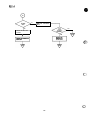
(2) Software initialization
Input of the ESC C2 command also initialize the printer. Printer initialization by ESC C? code does not
perform functions (d) or(e) above. The settings changed by the last SelecType
operation are maintained.
(3) Panel initialization
This printer can be initialized by pressing the RESET button on the front panel. When the printer is
initialized in this method, the functions (b), (d) and (e) above are not performed. The settings changed
by the last SelecType operation are maintained.
1.6.7 Default Values
When the printer is initialized, the following default values are set:
Page position
The current paper position becomes the top-of-form position
Left and right margins
Released
Line spacing
1/6 inch
Vertical tabs
Cleared
Horizontal tabs
Every 8 characters (relative)
Q
,F
. ,.
Family number of type style
Last font selected from the panel
Download
Kept - software initialization
characters
Cleared - hardware initialization
Character spacing
Last pitch selected from the panel
Printing effects
Cleared
Printer condition
Not PAUSE
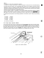
1.6.8 Sheet Loading and Sheet Ejection
The release lever has a disengage capability of tractor unit drive mechanism. Therefore, this printer
provides some improved paper handling in combination with the release lever.
. . ,-~.
G
Change the release lever to friction feed position and put’a cut sheet with the paper guide (rear or front ‘“’
(a) Automatic cut sheet loading without cut sheet feeder
insertion).
A few seconds laster, the cut sheet is automatically loaded to the top-of-form position.
(b) Automatic cut sheet loading & ejection with cut sheet feeder
Change the release lever to the friction feed position and the put cut sheets into the hopper of the cut
sheet feeder.
Pushing LOAD/EJECT button loads a sheet to the top-of-form positionlf
paper out is detected before
printing starts, a sheet is automatically loaded to the top-of-form position.
(c) Continuous paper loading & ejection (back-out)
Change the release lever to the rear push position or front push position, and set the continuous paper
into the tractor unit. Pushing LOAD/EJECT button loads the paper automatically to the top-of-form
position. If paper out is detected before printing statis, the paper is automatically loaded to the
top-of-form position.
F.<
if LOAD/EJECT button is pushed when continuous paper is loaded, the paper is ejected backward too
““
the push tractor unit.
1-22
REV.-A
When the paper is at the top-of-form position, the loading position is adjustable by using the ‘MICRO
FEED’ function. In the ‘MICRO FEED’ function, pushing the LINE FEED button pushes the paper forward,
and pushing the FORM FEED button pulls the paper backward.
The adjusted loading position is stored into the memory and remains to be effective until the power
is turned off. But the adjusted loading position of the continuous paper is memorized into nonvolatile
RAM, so it remains effective even if the power is turned off.
1.6.9 Tear-off Function
By pressing the TEAR OFF button when the tractor feed is selected, the paper is advanced to the tear
off position and ‘TEAR OFF’ indicator is lit.
In this condition (tear off condition), the tear off position is adjustable by using the ‘MICRO FEED’
functionln the ‘MICRO FEED’ function, pushing the LINE FEED button pushes the paper forward, and
pushing the FORM FEED button pulls the paper backward.
The adjusted position is memorized into the nonvolatile RAM and remains effective even if the power
is turned off.
If necessary to cancel this function, press the TEAR OFF button again or press the PAUSE button or
send subsequent data to the printer. Then the paper is fed back to the top-of-form position.
1.6.10 Adjust Lever Operation
The adjust lever must be set to the proper position according to the type of paper used.
Table 1-16. Lever Positions
Lever Position
Front side
I
Envelope
I Label
Rear side
I
Paper Type
I
Cut sheet
I Continuous paper I
Figure 1-11 Lever Positions
1-23
REV.-A
1.6.11
Printhead Protection
To keep the print quality, several kinds of printhead cleaning functions are performed automatically.
(1) Power on cleaning
Performed at power on when ‘(4) Cleaning’ as defined below is not required. It takes about several
seconds.
(2) Capping
In the following cases the printhead is capped. It takes about a second.
● Printing is stopped about 3 seconds.
● Entering the PAUSE condition.
(3) Refresh nozzles
Performed about every 15 seconds during printing. It takes less than a second.
(4) Cleaning
In the following cases the printhead cleaning is performed and it takes about 20 seconds.
● Turning the power on when the printhead has not been capped.
● Turning the power on more than 7 days after the last cleaning.
. Pressing the CLEANING button.
1.6.12 Ink Charge
Install the ink cartridge to the printer and turn the printer power on while pressing the CLEANING switch
down. The ‘Ink Charge’ function is started. It takes about 3 minutes to complete this functionlt is needed
only at the first time the new printer is used.
1.6.13 Ink End Detection
If ink end sensor detects ink end condition, ‘INK END’ indicator blinks performing 200 lines of printing,
and the printer enters the ink end condition. (’INK END’ indicator is lit.)
If ink cartridge is removed, ‘INK END’ indicator is lit and the printer enters the ink end condition
immediately.
1.6.14
Cover Open Detection
Cover open detector is installed to stop the printing whenever the printer cover is opened. If cover open
is detected, the printer enters the cover open error condition.
CAUTION:
Don’t open the printer cover while printing.
1-24
REV.-A
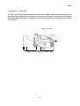
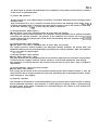
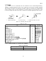
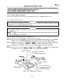
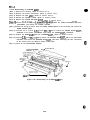
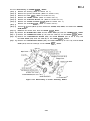
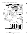
1.7 MAIN COMPONENTS
The main components of the SQ-870/l 170 printer are designed for easy removal and replacement
to facilitate maintenance and repair of the printer. The main components are:
1) C076 MAIN board:
the main control board; the CPU on this board controls all main functions.
2) Control panel unit
3) C076 PSB/PSE
4) M-47 10/4760:
board:
the power supply board.
the printer mechanism.
C076 PSB/PSE Board
C076 MAIN Board
\
- Printer Mechanism
M-4760
[
n
)4
1 ,
Figure 1-12. SQ-1 170 Component Layout
1-25
REV.-A
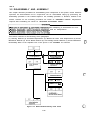
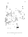
1.7.1 C076 MAIN Board (Main Control Circuit Board)
The C076 MAIN board is the main board in the printer, and contains a logic circuit and printer
mechanism driver circuit.
The KPD70325 (location: IC5) is used, and the following memories and gate arrays are assigned in the
1 M byte memory space.
Memories
5 12K\l M bits program ROM
:Ic14
1 M bits PS-RAM
:IC 1 9 / 2 2 / 2 3
8M\4M\2M/l M bits mask ROM (C.G)
:lC3/4/24
Gate Arrays
Memory management unit (E05A65)
:Ic12
Motor control unit (E05A48)
:Iclo
.,; ,... \
c’
Driver
CR motor (DC motor) driver (SLA4391)
:Ic17
PM motor (DC motor) driver (SDH03)
:IC16
PF motor (Stepping motor) driver (STK67 12B)
:Ic 11
Printhead driver (MPD 16322)
:lC8/9
Others
EEPROM
:IC2
Reset IC (MB3771)
:IC21
Reset IC (PST529C)
:IC7
Switching Regulator (TL494)
:IC20
Lithium battew
:BAT 1
A lithium battery in the battery circuit backs up the head cleaning timer while the printer power is off.
GA E05A48
(Iclo)
\
CPU PPD70325 P-ROM 5 12K
(IC14)
(IC5)
I
00 ❑ n =
o’
~o
II ~11
II
IJOQ
000
I
‘
n ‘N ‘L
Mu
1--1
b
I
BAT1/
1 M PS-RAM
(IC19)
0
u “p-RAM
,~i
GA L05A65 (1C12)
Figure 1-13. C076 MAIN Board
1-26
4-
(IC22))
REV.-A
1.7.2 Control Panel
The Control Panel is, which includes the indicator LEDs, switches, and DIP switches.
Figure 1-14. Control Panal
1.7.3 C076 PSB/PSE Board (Power Supply Circuit Board)
The power supply unit consists of a switching regulator circuit, which converts the AC line voltage to
the DC voltages (for example, + 35V and + 5V) used by the printer. The C076 PSB board is 120V input
type, and the C076 PSE board is 220/240V input type.
❑
o
PI
0
Figure 1-15. C076 PSB/PSE Board
1-27
REV.-A
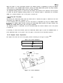
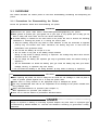
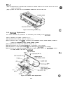
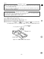
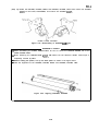
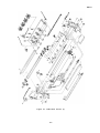
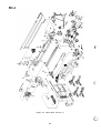
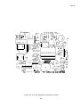
1.7.4 Printer Mechanism (M-4710/4760)
The M-47 10/4760 printer mechanism was developed specifically for SQ-870/l 170 printer. Included
the components are a carriage motor, carriage mechanism, paper-feed motor, paper-feed mechanism,
TE motor, top edge holding mechanism, pump motor, pump mechanism, printhead, and sensors. This
printer mechanism allows three ways of paper insertion.
o+:., . -.
,’
Figure 1-16. Model-4710/4760 Printer Mechanism
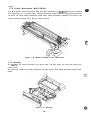
1.7.5 Housing
The LQ-870/l 170 housing consists of the upper, lower, and front cases. The front case houses the
control panel.
The lower case contains the printer mechanism, the main control circuit board, and power supply circuit
board.
Figure 1-17. Housing
1-28
REV.-A
CHAPTER 2
OPERATION PRINCIPLES
2.1
OPERATING PRINCIPLES OF PRINTER MECHANISM..............2-1
2.1.1.
Printhead Mechanism .............................................................2.2
2.1.2. Carriage Mechanism ...............................................................2.4
2.1.3.
Paper Feed Mechanism ..........................................................2.6
2.1.3.1 Paper Feeding Mechanism.....................................2-6
2.1.3.2 Release Lever Operation.........................................2.8
2.1.3.3 Paper Insertion entrance ........................................2.l O
2.1.3.4 Top Edge Holder Mechanism Operation ...........2 -13
2.1.4 Ink Mechanism . . . . . . . . . . . . . . . . . . . . . . . . . . . . . . . . . . . . . . . . . . . . . . . . . . . . . . . . . . . .. ..............2 -14
2.1.4.1 Pump Motor ................................................................2.l 5
2.1.4.2 Pump Mechanism .....................................................2.l 6
2.1.4.3 Cap Mechanism .........................................................2.l 7
2.1.4.4 Cleaning Mechanism and Carriage Lock
Mechanism . . . . . . . . . . . . . . . . . . . . . . . . . . . . . . . . . . . . . . . . . . . . . . . . . . . . . . . . . . . . . . . ..2-18
.
2.1.4.5 Ink Cartridge and Ink End Sensor
Mechanism . . . . . . . . . . . . . . . . . . . . . . . . . . . . . . . . . . . . . . . . . . . . . . . . . . . . . . . . . . . . . . . . .2-20
.
2.1.4.6 Wasted Ink Drain Tank...........................................2.2l
2.1.4.7 Operational Sequence of Ink Mechanism ........2 -22
2.1.5 Case Open Interlock Switch..................................................2.26
2.2 OPERATING PRINCIPLES OF POWER SUPPLY CIRCUITRY..2-27
2.2.1 Voltage Allocation . . . . . . . . . . . . . . . . . . . . . . . . . . . . . . . . . . . . . . . . . . . . . . . . . . . . . . . . . . . . . . .. ...2-27
..
2.2.2 Operating Principles of Power Supply Circuitry ............2 -27
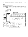
2.3 OPERATING PRINCIPLES OF CONTROL CIRCUITRY ...............2 -29
2.3.1
Control Circuitry Overview ...................................m.........mm.mmm.2.29
2.3.2
Reset Circuit ...............................................................................2-31
2.3.3
Detection Circuit .......................................................................2.31
2.3.4
Paper Feed Motor Drive Circuit ...........................................2-32
2.3.5
Carriage Motor Drive Circuit.................................................2.33
2.3.6
Printhead Drive Circuit ...........................................................2.34
2.3.7
Pump Motor Drive Circuit ......................................................2.36
2.3.8
TE Motor Drive Circuit ............................................................2.37
2.3.9
Timer Circuit and Backup Circuit ........................................2.37
2.3.10 EEPROM Control Circuit.........................................................2.38
z-i
REV.-A
LIST OF FIGURES
Figure 2-1.
Block Diagram of Printer Mechanism -Model
....
-47 10/4760 . . . . . . . . . . . . . . . . . . . . . . . . . . . . . . . . . . . . . . . . . . . . . . . . . . . . . . . . . . . . . . . . . . . . . . . . . . . .2-1
Figure 2-2.
Internal Structure of Printhead ..........................................2-2
Figure 2-3.
...
Structure of a Nozzle . . . . . . . . . . . . . . . . . . . . . . . . . . . . . . . . . . . . . . . . . . . . . . . . . . . . . . . . . . .2-2
Figure 2-4.
...
Printing Principle (1) . . . . . . . . . . . . . . . . . . . . . . . . . . . . . . . . . . . . . . . . . . . . . . . . . . . . . . . . . . . .2-3
Figure 2-5.
...
Printing Principles (2) . . . . . . . . . . . . . . . . . . . . . . . . . . . . . . . . . . . . . . . . . . . . . . . . . . . . . . . . . .2-3
Figure 2-6.
...
Printing Principles (3) . . . . . . . . . . . . . . . . . . . . . . . . . . . . . . . . . . . . . . . . . . . . . . . . . . . . . . . . . .2-3
...
Figure 2-7. Carriage Mechanism . . . . . . . . . . . . . . . . . . . . . . . . . . . . . . . . . . . . . . . . . . . . . . . . . . . . . . . . . . . .24
Figure 2-8.
...
Adjustment of Platen Gap . . . . . . . . . . . . . . . . . . . . . . . . . . . . . . . . . . . . . . . . . . . . . . . . . 2-5
Figure 2-9.
Friction Feed Method .............................................................2.6
...
Figure 2-10. Push Tractor Operation . . . . . . . . . . . . . . . . . . . . . . . . . . . . . . . . . . . . . . . . . . . . . . . . . . . . . .2-7
...
Figure 2-11. Push-Pull Tractor Method . . . . . . . . . . . . . . . . . . . . . . . . . . . . . . . . . . . . . . . . . . . . . . . . . . 2-8
Figure 2-12. Moving the Release Lever ....................................................2.8
Figure 2-13. Arrangement of Gears in Friction Feed
(or Full Release) ........................................................................2.9
Figure 2-14. Arrangement of Gears in Front Push Tractor Feed.....2-9
Figure 2-15. Arrangement of Gears in Rear Push Tractor Feed ......2-9
Figure 2-16. Top Entrance - Friction Feed Method .............................2-10
Figure 2-17. Rear Entrance - Push Tractor Method............................2-l O
Figure 2-18. Rear Entrance - Push-Pull Tractor Method ...................2-l 1
.
Figure 2-19. Front Entrance - Friction Feed Method . . . . . . . . . . . . . . . . . . . . . . . . .2-11
.
Figure 2-20. Front Entrance - Push Tractor Method . . . . . . . . . . . . . . . . . . . . . . . . .2-12
Figure 2-21. Front Entrance - Push-Pull Tractor Method..................2-l 2
Figure 2-22. Top Edge Holder Mechanism ...............................................2-l 3
Figure 2-23. Outline Ink Mechanism System .........................................2-14
....
Figure 2-24. Pump Motor . . . . . . . . . . . . . . . . . . . . . . . . . . . . . . . . . . . . . . . . . . . . . . . . . . . . . . . . . . . . . . . . . . . . . . . . . . .2-15
...
Figure 2-25. Pump Movement . . . . . . . . . . . . . . . . . . . . . . . . . . . . . . . . . . . . . . . . . . . . . . . . . . . . . . . . . . . . . . . . . . .2-16
....
Figure 2-26. Cap Movement . . . . . . . . . . . . . . . . . . . . . . . . . . . . . . . . . . . . . . . . . . . . . . . . . . . . . . . . . . . . . . . . . . . . . . 2-17
...
Figure 2-27. Air Inlet Operation . . . . . . . . . . . . . . . . . . . . . . . . . . . . . . . . . . . . . . . . . . . . . . . . . . . . . . . . . . . . . . .2-17
...
Figure 2-28. Cleaner Blade Operation . . . . . . . . . . . . . . . . . . . . . . . . . . . . . . . . . . . . . . . . . . . . . . . . . . . . 2-18
...
Figure 2-29. Rubbing Block Operation . . . . . . . . . . . . . . . . . . . . . . . . . . . . . . . . . . . . . . . . . . . . . . . . . . . 2-18
...
Figure 2-30. Set/Reset of Cleaner Lever . . . . . . . . . . . . . . . . . . . . . . . . . . . . . . . . . . . . . . . . . . . . . . . 2-19
Figure 2-31. Carriage Lock............................................................................2- 19
..
Figure 2-32. internal Structure of Ink Cartridge . . . . . . . . . . . . . . . . . . . . . . . . . . . . . . . . . 2-20
Figure 2-33. Structure of Ink Cartridge Holder......................................2-2l
..
Figure 2-34. Structure of Wasted Ink Drain Tank . . . . . . . . . . . . . . . . . . . . . . . . . . . . . . 2-21
z-ii
.....
L
REV.-A
Figure 2-35. Operational Sequence of Ink Mechanism and
Carriage Position .....................................................................2.22
Figure 2-36. Interlock Switch . . . . . . . . . . . . . . . . . . . . . . . . . . . . . . . . . . . . . . . . . . . . . . . . . . . . . . . . . . . . . . . . . . . .. ..2-26
Figure 2-37. Power Supply Circuit Block Diagram .................,.............2-28
Figure 2-38. Control Circuitry Block Diagram ........................................2.29
Figure 2-39. Reset Circuit Block Diagram ...............................................2-3 1
..
Figure 3-40. Detection Circuit Block Diagram . . . . . . . . . . . . . . . . . . . . . . . . . . . . . . . . . . . . . 2-31
Figure 2-41. Paper Feed Motor Drive Circuit..........................................2.32
Figure 2-42. Carriage Motor Drive Circuit ...............................................2.33
Figure 2-43. Printhead Drive Circuit..........................................................2.34
Figure 2-44. Charge/Discharge Circuit .....................................................2.35
Figure 2-45. Head Charge Condition..........................................................2.35
Figure 2-46. Head Discharge Condition ....................................................2.35
Figure 2-47. Timing for Discharge/Charge Pulse..................................2-36
Figure 2-48. Block Diagram of Pump Motor Drive Circuit.................2-36
Figure 2-49. Block Diagram of TE Motor Drive Circuit.......................2-37
Figure 2-50. Block Diagram of Timer Circuit/Backup Circuit ..........2-37
Figure 2-51. EEPROM Control Circuit .......................................................2.38
LIST OF TABLES
Table 2-1. Paper Feeding Method and Paper Entrance.......................2-6
Table 2-2. Rotational Direction and Operation of Each Part ............2 -15
Table 2-3. Ink End/Ink Cartridge Signal ...................................................2.2O
Table 2-4. Ratings of Power Supply Board..............................................2.27
..
Table 2-5. Voltage Allocation . . . . . . . . . . . . . . . . . . . . . . . . . . . . . . . . . . . . . . . . . . . . . . . . . . . . . . . . . . . . . . . . . . . . 2-27
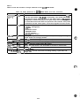
Table 2-6. Major Elements on C076 MAIN Board and
Their Functions . . . . . . . . . . . . . . . . . . . . . . . . . . . . . . . . . . . . . . . . . . . . . . . . . . . . . .....................2
...
-30
Table 2-7. Carriage Motor Drive Modes ...................................................2.33
Z.iii
REV.-A
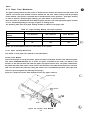
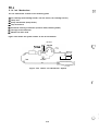
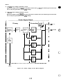
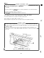
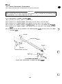
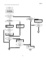
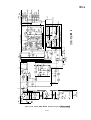
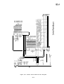
2.1 OPERATING PRINCIPLES OF PRINTER MECHANISM
This section describes functions and operations of the printer mechanism - Model-47 10/4760.
Modei-47 10/4760 is a serial type printer mechanism with a 48-nozzle printhead.
This printer mechanism consists of the printhead unit, paper feed unit, ink mechanism, and sensors.
Figure 2-1 shows the block diagram of the printer mechanism – Model-47 10/4760.
LOCK
s
Cover
Open
i
PF PE/FPE/R F/T
TE EDGE
B1
M S S
Paper Feed
S
M
IE IE2
CM EN TH DG HEAD
PM
S
TE Holder
G=-
I t-nnmeau
.......1
1
I
Ink
Cartridge
I I Punp Unit
I . &:y:e:aln[
I (Cap, Cleaner)~i
Figure 2-1. Block Diagram of Printer Mechanism - Model-471 0/4760
2-1
1
REV.-A
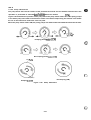
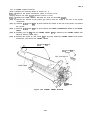
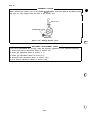
2.1.1 Printhead
Mechanism
The printhead of this printer employs the on-demand method, where part of the ink stored in the reservoir
within the printhead is supplied into the nozzle each time ink in the nozzle chamber is injected.
Figure 2-2 shows the internal structure of the printhead. The functions of the major components are
explained below.
● Head damper
When the carriage moves, the ink tube also moves, which results in the change of pressure within the
tube. The head damper is used to absorb this change of pressure and prevent the ink from rushing into
the reservoir.
● Reservoir
The ink supplied into the printhead is once stored in the reservoir.
O Nozzle
,,
‘~~~
The ink stored in the reservoir is injected through nozzles. The structure of a nozzle is shown in Figure&
2-3.
Reserver
Piezoelectric Element
Ink Inflow Gate
/<”,’/
- - - - - - ’ . \
,’
I
I
I
I
/;
I
II
1 \-,/’
I
—
\
\
\
—
1
\
——
—.-
/
;
/
\
\
‘ Filter
Nozzle
Figure 2-2. Internal Structure of Printhead
Diaphragm
!3\
‘ozzem
/
Piezoelectric
Element
T
\ Pressure
Chamber
Figure 2-3. Structure of a Nozzle
2-2
-Damper
REV.-A
< Printing >
This section describes how ink is injected through the nozzles.
(1) Normal condition ---Piezoelectric Element is electrically charged and bent inward.
Piezoelectric Element
/
(
)
Figure 2-4. Printing Principle (1)
(2) Charging operation --When the electric charge of the piezoelectric element is gradually discharged,
the element is bent outward to let ink into the pressure chamber.
Pressure Chamber
I
1
Figure 2-5. Printing Principles (2)
(3) Injecting operation --The ink in the pressure chamber is injected when the piezoelectric element
is quickly charged and bent inward.
1
1
Figure 2-6. Printing Principles (3)
When charging ink or cleaning the printhead, the ink in the pressure chamber is vacuumed out by the
pump. When printing, on the other hand, the ink is simultaneously injected and supplied according to
the change of volume of the pressure chamber.
This printer is provided with the function to change the printhead drive voltage corresponding to the
ink temperature, because the viscosity of the ink is subject to change depending on the ink temperature.
A thermistor is attached on the carriage to detect the ink temperature. When the ink temperature is
low (i.e. the viscosity is high), the printhead drive voltage is increased, or vice versa.
The temperature signal is fed back to the printhead drive voltage control circuit to adjust the voltage
to a proper level.
2-3
REV.-A
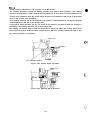
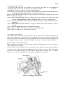
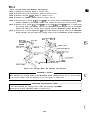
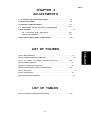
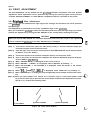
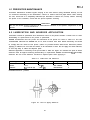
2.1.2 Carriage Mechanism
The timing belt attached to the base of the carriage is driven by the carriage motor and the pulley. This
makes the carriage (printhead) move along the guide shafts.
A scale made of polyester (DETECTION, PLATE, PTS) is provided along the motion range of the carriage.
The optical linear encoders mounted on the carriage scan this scale and output one pulse of signal each
time the carriage moves 1/1 20 inch. The signal consists of Phase-A and Phase-B, which are 90 degrees
different from each other. Therefore, the controller can recognize the moving direction of the carriage
by detecting this difference. The controller can also recognize the carriage speed from the signals sent
from the encoders.These signals are also used to adjust print timing.
This printer is not provided with a home position sensor. Instead, the carriage is designed to hit the
left stroke end each time the printer is initialized. At this time, the controller resets the carriage position
counter to “O” and then counts up/down pulse signals sent from the encoder to determine the carriage
position.
c’
-.
$s2
.
Carriage
k
>:”
/
/
SHAFT, CR, GUIDE, MAIN
A
/Timing Belt
Carriage
Motor
m
Figure 2-7. Carriage Mechanism
2-4
REV.-A
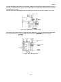
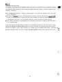
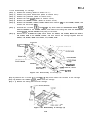
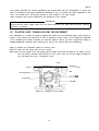
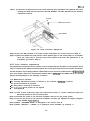
< Adjustment of Platen Gap >
The platen gap must be adjusted with the head adjust lever (LEVER, GAP, ADJUST) depending on the
thickness of paper. When the head adjust lever is operated, it turns the carriage guide shaft (SHAFT,
CR, GUIDE, MAIN) and makes the carriage closer/farther to/from the platen. (The shaft has an eccentric
cross section.)
LEVER, GAP, ADJUST
r
\
\
L—.
o
Figure 2-8. Adjustment of Platen Gap
2-5
REV.-A
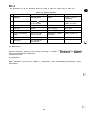
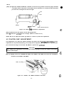
2.1.3 Paper Feed Mechanism
The paper feeding method for this printer is divided into the friction feed method and the tractor feed
method. The tractor feed method is further divided into the push tractor method and the push/pull
tractor method. (This printer is provided with a standard tractor which performs “’push-type” feeding.
In order to perform “push/pull-type” feeding, you must attach an optional tractor.)
Also, this printer is provided with three different paper insertion. The most appropriate paper insertion
is to be selected depending on the type of paper or feeding mode.
The following table lists each paper feeding method in relation to the paper path.
Table 2-1. Paper Feeding Method and Paper Entrance
Paper Insertion (Paper Path)
Paper Advance
Method
Rear Entrance
Front Entrance
OK
No
OK
Push tractor Feed
No
OK
OK
Push-pull Tractor
Feed
No
OK
OK
Top Entrance
Friction Feed
A
NOTE: Pull Tractor Method cannot be used alone on this printer.
2.1.3.1 Paper Feeding Mechanism
The details of each paper feed method is described below.
Friction Feed Method
The cut sheet paper is held by the platen, paper feed rollers, and paper tension roller. When the paper
feed motor (STEPPING MOTOR, PF) is driven, the gears connected to the motor are rotated in the
direction of the black arrows and rotate the platen and paper tension roller. The paper held between
the platen and paper feed rollers is thus driven in the direction of the white arrows by means of friction
feed. You can release the paper by setting the release lever to Full Release position. (The paper feed
rollers are pressed against the platen by the springs.)
Figure 2-9. shows the friction feed method from the top paper entrance.
/“- . .
k
/7\Q
.
Cut-Sheet Paper
.
\
.’
r F?ed
r
w
Figure 2-9. Friction Feed Method
2-6
REV.-A
Push Tractor Method
In this method, continuous paper is engaged to the tractor by mating the holes of paper to the pins
of tractor. When the paper feed motor (STEPPING MOTOR, PF) is driven, the gears connected to the
motor are rotated in the direction of the black arrows and rotate the platen, paper tension roller, and
push tractor. The paper is thus driven in the direction of the white arrow as pushed by the push tractor
pins and pulled by the paper tension roller.
In this method, the release lever must be set to Push Tractor position, where the paper feed rollers are
set free from the platen.
Figure 2-10 shows the push tractor method from the rear entrance and the front entrance.
/-’--=..
.’
/
Platen
/“
c>’’””””’ “P”
Rear Entrance
/
\
./
%.
> AZ=/’
‘(u
\
Front
\
Entrance
Uz
–’
Front Push
Tractor
Figure 2-10. Push Tractor Operation
2-7
--Rear
Push
Pajer
Feed
Motor
REV.-A
Push-Pull Tractor Method
This method is a combination of the above-mentioned push tractor method and the pull tractor method.
The push tractor pushes the paper toward the printhead, while the pull tractor pulls the paper from
the printhead. This provides more accuracy in paper feeding operation.
Figure 2-11 shows the push-pull tractor method from the rear feeding slot.
w
,’
/
Pull Tractor
,,fi
.“ /
\\
\~
Rear Push Tractor
/,/
/
t}
Paper Feed
~
“?or
w
Figure 2-11. Push-Pull Tractor Method
2.1.3.2 Release Lever Operation
The friction feed method and the tractor feed method can be switched to each other with the release
lever (LEVER, RELEASE, MAIN). When the release lever is set to the Friction Feed position, the paper
feed rollers are made to contact the platen. When the lever is set to the Tractor position, on the other
hand, the paper feed rollers are set free from the platen. The position of the release lever is detected
by the Release Sensor (CONNECTOR SWITCH).
dF
~
Release Lever
H’aper’uide
8
hY?o
\ Release Sensor
Pa~er “Feed Roller
Fiaure 2-12. Movina the Release Lever
2-8
REV.-A
When the release lever is shifted as described above, the arrangement of the gears is changed
accordingly to enable various types of paper feeding operation (such as front push tractor feeding or
rear push tractor feeding) or to disable either.
Therefore, you can set continuous paper to each push tractor (front and rear) and switch between the
two only by shifting the lever.
Platen Gear (Platen Drive)
Roller
Pinion Gear
o
Front
GEAR, 34.5
Figure 2-13. Arrangement of Gears in Friction Feed (or Full Release)
o
Front
Tractor Gear
Figure 2-14. Arrangement of Gears in Front Push Tractor Feed
Tractor Gear
Right Frame
Figure 2-15. Arrangement of Gears in Rear Push Tractor Feed
2-9
REV.-A
2.1.3.3 Paper Insertion entrance
The foIlowing few pages describe the paper feeding method in relation to the paper feeding insertion.
Top Entrance
The top entrance is used in the friction feed method. The paper inserted through this entrance is
detected by the rear PE sensor (DETECTOR ASSY., REAR).
ear PE Sensor
Rollers
u
“
Figure 2-16. Top Entrance - Friction Feed Method
Rear Entrance
The rear entrance is used in the tractor feed method (Push tractor method or Push-pull tractor method).
The paper inserted through this entrance is detected by the rear PE sensor (DETECTOR ASSY., REAR).
Paper
Paper
Roller
Tension\
.
~ y’ ‘“’de
‘“p’at&
7
I y Rear Entrance
PR
.- , “Jilr
1
Figure 2-17. Rear Entrance - Push Tractor Method
2-10
REV.-A
Paper
Paper Tension Roller
Printhead
Rear PE Sensor
Figure 2-18. Rear Entrance - Push-Pull Tractor Method
Front Entrance
The front entrance is used in the friction feed method or the tractor feed method (Push tractor method
or Push-pull tractor method). The paper inserted through this entrance is detected by the front PE sensor
(DETECTOR, PE, FRONT).
Paper
Paper Tension Roller
Printhead
Roller
Paper Feed Roller
Figure 2-19. Front Entrance - Friction Feed Method
2-11
REV.-A
Paper
Paper Tension Roller \
/-
Printhead
Front PE Sensor
Figure 2-20. Front Entrance - Push Tractor Method
Paper,
Pull Tractor
Paper Tesion Roller
\
A
x - i /
1
‘7
I
Pnnthead
4
Front PE Sensor
/
~Front Push Tractor
Figure 2-21. Front Entrance - Push-Pull Tractor Method
2-12
c
.,. .‘ ~
L
REV.-A
2.1.3.4 Top Edge Holder Mechanism Operation
This mechanism is provided to minimize unprintable area at the top edge of paper. The top edge of
paper fed around the platen is held by the top edge holder plate until the top edge is delivered to the
position where the paper tension roller comes down to hold the paper.
In detail, the top edge holder plate catches the top edge of the paper when the paper is initially fed
around the platen, and then rotates along with the platen while holding the paper. When the top edge
of paper reaches the position where the paper tension roller comes down to hold the paper, the top
edge holder plate is enclosed behind the eject guide plate.
The TE (Top Edge) sensor is used to detect whether or not the top edge of paper is at the position to
be held by the holder plate. It consists of a photo sensor which emits light toward the paper and detects
the reflected light.
The top edge holder plate is driven by the TE motor (a stepping motor) (STEPPING MOTOR, TOP EDGE
HOLDER).
:\l’-
T OD Edae Holder Plate
,,
Lett
Frame
(
Platen
\
c ’
/ “
,/’--
,C------l -— —
/
r!,r‘: 1 (Printhead)
I F, - - 1,0
~--+ 1;
/
\
?&
0
(
TE Sensor
\’;y------
j \ \ \ “=’r-”’L--\
‘-— \ o j )
\
\
\
“-’ >TE M o t o r
“=..-/”
Figure 2-22. Top Edge Holder Mechanism
2-13
REV.-A
c~. :.
2.1.4 Ink Mechanism
,’.,, ,...,
The ink mechanism consists of the following parts.
Ink cartridge (Ink cartridge holder, Ink end sensor, Ink cartridge sensor)
Pump unit
Pump mechanism (Pump motor)
Cap mechanism
Printhead cleaning mechanism (Cleaner blade, Rubbing blade)
Carriage lock mechanism
Wasted ink drain tank
Figure 2-23 shows the system outline of the ink mechanism.
, CR Valve
(--)
-. .,
Pnnthead
(iiP
u
Wasted Ink
Drain Tank
I
/
1
Pump Motor
/ Ink Tank
Figure 2-23. Outline Ink Mechanism System
(’
2-14
REV.-A
2.1.4.1 Pump Motor
The pump motor drives the pump, cleaner blade, rubbing blade, and carriage lock lever (set/reset)
through several gears.
Pump Motor
r
Cleaning Blade
Drive Gear
1
.
Gear
I
Cleaner Lever
Rubbing Cleaner
Blade
CR Stopper
Figure
2-24. Pump Motor
Table 2-2. Rotational Direction and Operation of Each Part
Rotational
Direction
Ccw
Operation of Each Part
Resets the carriage lock.
Pumps ink into the wasted ink drain tank.
Reset the cleaner blade.
Resets the rubbing blade.
Sets the carriage lock.
Resets the pump.
Sets the cleaner blade.
Cw
2-15
REV.-A
2.1.4.2 Pump Mechanism
The pump draws ink from the nozzles of the printhead and sends it to the wasted ink drain tank. This
operation is performed to eliminate dust./bubbles within the nozzles.
Figure 2-25 illustrates the operation of the pump. When the pump motor rotates CCW, the pulley pumps
in the wheel pump unit rotate in the direction of the arrow while compressing the ink tube. This makes
the ink in the tube move toward the used ink pack.
When the pump motor rotates CW, the pulley pumps are shifted inward and detached from the ink tube.
Pumping (Pump motor:CCW)
@.@+@
No Pumping (Pump motor:CW)
Wheel Pumo
c
‘+
“/’
Pulley Pump
No Pumping (CW)
Pumping (CCW)
Figure 2-25. Pump Movement
2-16
REV.-A
2.1.4.3 Cap Mechanism
This mechanism is provided to prevent the nozzles from drying or forming bubbles while they are not
used. In this mode, when the pump is driven with the cap closely contacted to the nozzles, the internal
pressure of the capped section becomes lower than that of the printhead section. This causes the ink
in the printhead to flow toward the pump through the cap.
The capping is automatically performed when the carriage hits the left stroke end. At this time, the cap
covers the printhead nozzles while the slider valve closes the air inlet.
When the carriage moves right ward in this condition, the slider valve is released from the air inlet and
allows the air to enter the capped section, so that the cap can be easily separated from the printhead.
Carriage Movement
-
Carriage
Inl
Negative Pressure
--w17%
Air and
Wasted Ink
4
/
To Wasted
$
Ink Drain Tank
Figure 2-26. Cap Movement
Carriage Movement
Slider
Valve
Q
/
popen
—Air
Inlet
‘ Close
Air
Figure
2-27. Air Inlet Operation
2-17
REV.-A
2.1.4.4 Cleaning Mechanism and Carriage Lock Mechanism
The cleaning operation consists of rubbing operation and cleaner blade operation. (The rubbing
operation is performed to remove head preserving liquid, ink, or dust which is heavily adhered to the
surface of the printhead, while the cleaner blade operation is performed to remove ink or dust lightly
stuck to the surface of the printhead.)
In the rubbing operation, the ink, etc. adhered to the nozzles is rubbed off when the carriage is repeatedly
rubbed against the pad set in the carriage path.
In the cleaner blade operation, the ink, etc. stuck to the nozzles is scraped off when the carriage is
repeatedly passed along the blade set in the carriage path.
The rubbing pad and the cleaner blade are united into a single part. When the carriage moves from
left to right, the cleaner blade operation is performed. Or when the carriage moves from right to left,
the rubbing operation is performed.
Cleaner Lever
o..
Movement
Prin;head
/
Cleaner Blade Side (Rubber)
Figure 2-28. Cleaner Blade Operation
/
L%
Cleaner Lever
/
2arriage
?ent
m
Rubbing Blade
Side [Pad)
-Printhead
Figure 2-29. Rubbing Block Operation
2-18
c.’
REV.-A
The pad and blade is attached to the cleaner lever. When the pump motor rotates clockwise, the spur
gear (20) is rotated and thus sets the lever forward. When the pump motor rotates counter-clockwise,
the cleaner lever is reset.
The spur gear will be disengaged from the cleaner lever as soon as the lever is either set or reset.
Cleaner Lever
Printhead
Figure 2-30. Set/Reset of Cleaner Lever
The cleaner lever is also used as a carriage lock lever. When the printhead is locked in the capped state,
this lever functions as a printhead holder and prevents the cap from coming off in a shock.
ner Lever
riage Stopper
Print
riage
Figure 2-31. Carriage Lock
2-19
REV.-A
2.1.4.5 ink Cartridge and Ink End Sensor Mechanism
The structure of the ink cartridge is shown in Figure 2-32.
The ink cartridge contains an ink pack and an ink end detection plate. The detection pIate gradually
sticks out as the ink inside the cartridge runs short. The ink end sensor (DETECTOR ASSY., INK) is
designed to detect this plate.
Ink End Detection Plate
\
c
Ink Pack
/
/
[:
Figure 2-32. Internal Structure of Ink Cartridge
Figure 2-33 shows the structure of the ink cartridge holder.
When the ink cartridge is installed, the ink supply needle breaks the ink pack so that the ink inside the
pack is supplied. There are two micro switches within the ink cartridge holder - Ink End Sensor
(DETECTOR ASSY., INK) and Ink Cartridge Sensor (HOLDER ASSY., INK CARTRIDGE). The ink end sensor
detects the ink end detection plate, while the ink cartridge sensor detects the ink cartridge.
When an ink end condition is detected, the status will not be recognized until another 200 lines are
printed. When absence of ink cartridge is detected, however, the ink end signal will be immediately
activated with the cartridge signal.
Table 2-3. Ink End/Ink Cartridge Signal
I
Status
Ink Cartridge Exist/Ink Exist
IE Sensor
IC Sensor
IE Signal
IC Signal
Close
Close
LOW
LOW
Ink Cartridge Exist/Ink Not Exist
Open
Close
HIGH
LOW
Ink Cartridge Not Exist
Open
Open
HIGH
HIGH
Ink Cartridge Sensor
/
II
J
/
To
Printhead
Ink Supply
- ~Needle
#
!1 I
Ink End Sensor
Figure 2-33. Structure of Ink Cartridge Holder
2-20
I
. *:.,,. .,
(!2
REV.-A
2.1.4.6 Wasted Ink Drain Tank
Used ink is collected into the wasted ink drain tank. The wasted ink drain tank has the absorber to collect
used ink through the tube, and the opening which lets out the vapor from ink. This tank is provided
with a sufficient capacity to collect the waste ink that is used during the whole printer life.
From Pump
Wasted Ink
II
I
1
11
1
Absorber
J
Figure 2-34. Structure of Wasted Ink Drain Tank
2-21
REV.-A
2.1.4.7 Operational Sequence of Ink Mechanism
Ink Mechanism comprises of various steps of operation.
The following are some of the basic steps of operation.
● Ink flushing operation
In this operation, the printhead is moved to the position where the cap covers the nozzles (the refresh
position) and then ink is injected from all the nozzles toward the cap.
● Negative pressure release operation
This operation is performed to change of inside the cap air pressure from negative pressure to normal
pressure.
In this operation, the carriage is moved to the negative pressure release position, where the printhead
is closely contacted against the cap with the air valve opened. (The negative pressure inside the cap
is thus released.) Then the pump operates for 5 seconds to make the ink inside the cap flow toward
the wasted ink drain tank.
● Cleaner blade operation-1
This operation is performed to remove dust, etc. from the printhead. Refer to 2.1.4.4 for the details.
● Cleaner blade operation-2
This operation is performed to remove dust, etc. from the printhead following the ink charge operation.
It consists of the cleaner blade operation- and 3000-pulse ink flushing operation that follows.
● Cleaner blade operation-3
This operation is petformed to remove ink mist from the printhead. It consists of the l-second ink
discharge operation and the cleaning blade operation- that follows.
● Rubbing operation
This operation is performed to remove head preserving liquid, ink, or dust which is heavily adhered
to the surface of the printhead. Refer to 2.1.4.4 for the details.
‘.;;
The above operations are performed when the carriage is located at the position indicated below. o
Cap
Cleaner
Platen
Carriage
/
/
/
~-. *~-,i-,
,
l+ t
‘
/
/
;_. ~-->, :-J
h’
‘---x’
Printing Area
Left Side
I
Right Side
I
I
Negative Pressure
Release Area
-1
Bottom Side
I
I
I
I
=1
I
I
Flushing Area
Figure 2-35. Operational Sequence of ink Mechanism and Carriage Position
2-22
a..,
.=4
REV.-A
The basic steps of operation described above are combined in many ways to meet various conditions
of the printer as described below.
(1) Power ON operation
At time of power on, four different ways of operation are possible depending on the carriage position
and timer value.
They are described in a), b), c), d) below. The timer will be reset in the following cases; the CL1 or CL2
operation (described below) is performed, the initial charge operation (refer to this section) is performed,
or the timer indicates “7’’days or more when the power is turned on.
a) Carriage Position: Home position
● Timer Value: Less than 7/days/Less than 24 hours after last printing
The negative pressure release operation and 100-pulse flushing operation will be performed without
performing the cleaning operation. The purpose of this operation is to prevent ink in the printhead
nozzles from drying up by keeping the inside of the cap moistened. After this operation, the printhead
will be capped again.
b) Carriage Position: Home position
● Timer Value: Less than 7 days/More than 24 hours after last printing
The negative pressure release operation, and 2600-pulse flushing operation, 0.5 second waite, and
2600-pulse flushing will be performed without performing the cleaning operation. After this operation,
the printhead will be capped again.
c) Carriage Position: Home position
● Timer Value: More than 7 days
The pump performs the ink charge operation for 4 seconds to replace the ink in the tube. This operation
is followed by the negative pressure release operation, cleaner blade operation-2, and capping.
This operation is necessary because the ink kept inside the tube for more than 7 days is subject to
deterioration.
d) Carriage Position: Other than Home position
● Timer Value: Not relevant
The carriage will be moved to the home position followed by the cleaner blade operation-1. Then the
pump performs the ink charge operation for 2 seconds, followed by the ink discharge operation, cleaner
blade operation-2, and capping.
(2) Cleaning operation
This operation is performed to correct abnormalities such as injection failure (which results in missing
dots or deformed characters). This operation is enabled when the cleaning switch is pressed during
the pause mode. Three modes of operation are used depending on the number of lines printed since
the last cleaning operation.
2-23
REV.-A
a) CL1 (Normal cleaning)
This operation consists of the cleaner blade operation-1, negative pressure release operation, and
cleaner blade operation-2.
b) CL2 (Intensive cleaning)
This operation is performed when the cleaning switch is pressed before 200 lines are printed after the
last cleaning operation. In other words, the intensive cleaning is performed when the normal cleaning
fails to correct abnormalities.
This operation consists of the rubbing operation, ink charge operation for 7 seconds, negative pressure
release operation, and cleaner blade operation-2.
c) CL3 (False cleaning)
The false cleaning will be performed when the user presses the cleaning switch 6 times or more before
500 lines are printed after power on. This prevents the user from consuming an excessive a mount
of ink in performing the cleaning operation for too many times.
This operation consists of the cleaner blade operation-1, ink charge operation for 2 seconds with the . .
o
slider valve released, negative pressure release operation, and cleaner blade operation-2.
(3) Refreshing operation
This operation is performed to prevent the ink in the nozzles from getting sticky.
Two modes of operation are provided as follows.
a) Refreshing operation-1
This operation is performed every 15 seconds in the continuous printing mode. The carriage is moved
to the flushing position and then 10-pulse ink flushing operation will be performed.
b) Refreshing operation-2
This operation is performed after every 100 times of refreshing operation-1. It is followed by the cleaner
blade operation-3.
( ‘
(4) Waiting operation
This operation is performed when more than 3 seconds has passed after the last character is printed.
This operation consists of 2800-pulse ink flushing operation (or less, depending on the number of
cleaning operations performed so far), cleaner blade operation-3 (performed in some cases, also
depending on the number of cleaning operations performed so far), and capping.
(5) Initial charge operation
This operation is performed to replace the head preserving liquid with ink. It is performed when the
user operates the initial charge operation.
Three different modes of operation are used depending on the printer conditions.
+-:.i
,.
cl
2-24
REV.-A
a) Initial charge operation-1
This operation is performed when the printhead is not capped at the time the user operates the initial
charge operation. It consists of the cleaner blade operation-1, ink charge operation for 60 seconds,
negative pressure release operation, rubbing operation for 5 times, ink charge operation for 5
seconds, and negative pressure release operation. Then a series of rubbing operation (5 times), ink
charge operation (5 seconds), and negative pressure release operation will be repeated 3 times,
followed by the ink charge operation for 5 seconds, negative pressure release operation, and cleaner
blade operation-2.
b) Initial charge operation-2
This operation is performed when the printhead is capped at the time the user operates the initial
charge operation.
It consists of the ink charge operation for 60 seconds, negative pressure release operation, rubbing
operation for 5 times, ink charge operation for 5 seconds, and negative pressure release operation.
Then a series of rubbing operation (5 times), ink charge operation (5 seconds), and negative pressure
release operation will be repeated 3 times, followed by the ink charge operation for 5 seconds,
negative pressure release operation, and cleaner blade operation-2.
c) False initial charge operation
This operation is performed if one of the following conditions occurs when the user operates the
initial charge operation.
● The initial charge operation has been performed 6 times or more.
● The initial charge operation has been performed immediately after the previous one.
● The initial charge operation has been performed 4 times or more in one day.
This operation prevents the user from consuming an excessive amount of ink in performing the initial
charge operation for too many times.
This operation consists of the ink charge operation for 60 seconds with the slider valve released, pause
for 10 seconds, ink charge operation for 5 seconds with the slider valve released, and the negative
pressure release operation. A series of the above operations are repeated 3 times, followed by the ink
charge operation for 5 seconds with the slider valve released, negative pressure release operation, and
cleaner blade operation-2.
2-25
REV.-A
(6) Wasted ink drain tank replacement operation
In normal use condition, this tank has a sufficient capacity to collect all the ink to be wasted during
the whole printer life. However, if an unexpectedly large amount of ink is wasted in excessive cleaning
operations or power on operations, the tank may be fulfilled. In this case, the wasted ink drain tank
replacement message will be displayed to urge the user to replace the tank. (The tank will be actually
replaced by a service personnel as required by the user.)
The tank overflow condition is estimated in the following method; The total time spent for negative
pressure release operation is stored in terms of “points”in the non-volatile memory (EEPROM) on the
Main Board. If the time exceeds the predetermined value (4 1000 points), the replacement message
is displayed. The time spent for ink discharge operation is converted to “point’ ’values at the following
ratio.
2 seconds:
10 points
4 seconds:
23 points
5 seconds:
30 points
7 seconds:
40 points
60 seconds: 400 points
2.1.5 Case Open Interlock Switch
The carriage of this printer moves at a high speed, and the printhead is supplied with a high DC voltage.
To protect the user from the fast moving carriage and high voltage, the interlock switch is installed on
this printer. When the printer cover is opened during the printing operation, the interlock switch is
activated and mechanically cuts off the printhead drive voltage to reduce the torque of the carriage
motor by inserting the interlock resistor in series into the carriage motor drive circuit.
,1
Figure 2-36. Interlock Switch
.>
0
‘.4,”.
2-26
REV.-A
2.2 OPERATING PRINCIPLES OF POWER SUPPLY CIRCUITRY
The power supply circuitry of this printer is provided with either
C076PSB board (120V) or C076PSE
board (220/240 V). Both boards operate in the same way although the elements in the primary circuit
are partly different.
The power supply unit supplies DC voltage which is used for controlling the printer of driving the printer
mechanism.
Table 2-4 shows the ratings of the power supply board.
Table 2-4. Ratings of Power Supply Board
Board Name
Input Voltage (ACV)
Fuse (F I ) Rating
C076PSB
103.5-132
2.5 A/ 125 V
C076PSE
198-264
1.25 A/ 250 V
2.2.1 Voltage Allocation
The DC voltage generated by the power supply circuitry is allocated to each circuit or mechanism
depending on their voltage level. The details are described in Table 2-5.
Table 2-5. Voltage Allocation
Application
Voltage
+ 3 5 VDC
+ 5 VDC
Carriage motor drive
Paper feed motor drive
Top edge motor drive
Pump motor drive
Printhead drive voltage (VH) generation
C076 MAIN board logic circuit
Sensors
Control panel LED
Top edge motor holding
2.2.2 Operating Principles of Power Supply Circuitry
Figure 2-37 shows the block diagram of the power supply circuitry.
The AC power supplied from the external source is first sent to the filter circuit, where higher harmonic
is cut. The AC voltage is then rectified and smoothed into the DC voltage. This DC voltage is sent to
the switching circuit and then to the smoothing circuit of the secondary circuitry, and thus dropped
to +35 VDC voltage. This +35 VDC voltage is fed back to the switching circuit by the + 35V line voltage
detection circuit and thus stabilized.
The +35VDC voltage is also sent to the +5VDC power supply circuit and thus dropped to stable +5
VDC voltage.
This circuitry is provided with four types of protection circuits as described below.
1 ) + 5 VDC line over voltage/current protection circuit
When the current flowing on the + 5 VDC line increases, the over current protection circuit cuts
the current. When the voltage of the + 5VDC line exceeds a certain value (+ 7V), the switching circuit
is turned off to stop the generation of +35 VDC voltage. The over current protection circuit is
included in the over voltage protection circuit.
2-27
REV.-A
2) +35 VDC over voltage protection circuit
When the voltage of the +35 VDC line exceeds a certain value (+36V), the switching circuit is turned
off to stop the generation of +35 VDC voltage.
3) + 35VDC under voltage protection circuit
When the voltage of the +35VDC line goes lower than a certain value, the switching circuit is turned
off to stop the generation of +35 VDC voltage.
~
Power Supply Board
- - - - - - - - - - - - - - - - - - - - - - - - - - - - - - - - - - - - - - - - - - - - - - - - - - -I
I
I
1
!
I
I
I
I
I
I
I
I
I
I
I
I
I
I
I
I
I
1
❑
Smoothing
~ Circurt
I
I
I
1
I
I
I
I
I
1
1
I
I
I
11-
; Secondary ~WT
I
Circuil
I
Primary
I
t
I
I
I
1
I
I
A
t
h
Filter
Clrcult
I
I
I
I
I
I
I
I
I
I
I
~ —e +5 Voc
I
1
I
t
I
I
-1
-+- +
I
I
I
I
+35 line
Detector
Circuit
I
I
i
I
I
I
1
f
1
I
+5 line
Voltage
Overload
Protection
Cirwit
I
I
I
I
I
i
I
I
I
I
I
I
i
I
1
I
1
I
#
I
1
I
I
I
I
I
I
I
I
I
I
I
I
I ----
+35 line
Voltage
Overload
Protection
Circuit
+35 line
Voltage
Drop
Protection
Circuit
------- ------------------------
------- -------
+
AC Input
Figure 2-37. Power Supply Circuit Block Diagram
-
-
I
I
I
I
I
I
I
I
I
i
I
I
I
1
I
I
I
I
I
I
I
I
I
I
I
f
I
1
I
I
I
I
I
!
I
1
-
+35VOC
REV.-A
2.3 OPERATING PRINCIPLES OF CONTROL CIRCUITRY
This section describes the operating principles of the control circuitry of this printer - C076 MAIN
board.
2.3.1 Control Circuitry Overview
The C076 MAIN board is provided with wPD70325 (V25 +) (9.5 MHz) – a 16-bit one-chip microprocessor, E05A65 - a gate array with memory management function, and E05A48 – a gate array
to control DC motors. Figure 2-38 shows the control circuitry block diagram.
—--—-——7
I – – - – – -1
I
{ C o n t r o l ~ Case Open ~
I
,
Panel
~
j Sensor
- - - - - - - -I
l–- - - C076 MAIN Board
,
- - - - - - - - - - - - - - - - - - - - - - - - - - –---------–,?
- - – - - – - - - - – -
I
I
I
I
I
I
I
I
I
I
I
I
I
1
I
I
I
I
I
I
I
I
I
Parallel
l/F
;D
GA
E05A65
IC12
I , – - - - - –,
1
1“
Option
~
I ~
I
I , l/F
I I - – - - – J
I
n
E
EEPROM
IC2
SLA4391
IC17
I
I
I
I
I
I
I
I
I
I
I
I
I
I
I
I
I
I
1
I
r
I
I
I
I
I
I
L3
uPD1 6322
IC8,9
PU1501
IC18
SOH03
IC16
l --------- -------
STK
6712B
Icll
El 3
Battery
t
- - - - - - - - I
I
Reset
Circuit
I
I
I
I
I
I
I
I
I
— - _ --- _--—---— -— —--- —- —— -- . _ _ - — - _ - — — - - - — - — - —I
Figure 2-38. Control Circuitry Block Diagram
2-29
REV.-A
Table 2-6 lists the functions of major elements on the C076 MAIN board.
Table 2-6. Major Elements on C076 MAIN Board and Their Functions
Element
r
Location ~
wPD70325
(V25 +)
IC5
E05A65
Ic12
Function
The CPU of this board. It receives data from the host and stores (V25 +)
‘ it in the input buffer in PS-RAM by interrupting. The stored data is then
converted to image data and stored in the image buffer in PS-RAM. The
image data is then transmitted to the gate array, where the image data
is converted to the serial data. This processor also controls each printer
mechanism and the control panel, and receives signals from each sensor.
This gate array executes the following functions.
. Memory management
1/0 Port
Printhead control
. EEPROM control
. Parallel interface
.Control panel control
●
●
i05A48
Ic 10
This gate array controls the carriage motor (DC motor) by detecting the
motor speed and carriage position.
SLA4391
Ic17
This IC drives the carriage motor (DC motor).
>TK67 12B
Ic 11
This IC drives the PF motor (Stepping motor).
50H03
~PD 16322
ICI 6
This IC drives the pump motor (DC motor).
IC8,9
These are head drivers. The head data is received in serial mode.
t140B03
IC4
I M
PS-RAM I C19
(IC22)
I These ICS (Mask-ROM) are character generators. The font data is stored
! in these ROMs.
1 This RAM is used to store CPU’s working memory, input data, and
~ image data.
.,-.. .. .
0
2-30
REV.-A
2.3.2 Reset Circuit
When the power in turned on, the reset IC(MB3771 ), which monitors the + 5 VDC line, keeps outputting
RESET signals until +5 VDC is stable. This controller can also reset itself by setting RSTRG signal(160
pin of E05A65 gate array) to LOW. The block diagram of this circuit is shown in Figure 2-39.
GA
E05A65
IC12
RSTRG
+5V
A
160
MB3771
IC21
6
8
RESET
Figure 2-39. Reset Circuit Block Diagram
2.3.3 Detection Circuit
This printer is provided with 1 sensors, but only 7 sensors are described in this section. They are Ink
Cartridge Sensor, Ink End Sensor, Platen Gap Sensor, Friction/Tractor Select Sensor, Top Edge Sensor,
Paper End Sensor (Front), and Paper End Sensor (Rear). The signals from these sensors are directly
inputted to the CPU port.
For the other sensors, refer to each circuit as follows.
●
●
●
●
Ink temperature detector (Thermistor)
---Head drive circuit
+ 35VDC under voltage detection circuit---EEPROM control circuit
Case open sensor (interlock switch)
---Head drive circuit /Carriage motor drive circuit
Encoder
---Carriage motor drive circuit
IE2
PT7
E
PT6
PT5
GAP
Ffi
CPU
V25+
IC5
PT4
PT3
EDGE
PE
PT2
PT1
PE(Rear)
“3
Figure 3-40. Detection Circuit Block Diagram
2-31
REV.-A
2.3.4 Paper Feed Motor Drive Circuit
A stepping motor is used in the paper feed motor drive circuit of this printer.
The motor is driven by 2-2 phase excitation and constant-current arrangement. For a single pulse, paper
is fed 1/360 inch (minimum value). The acceleration/deceleration control is not applied to the paper
feed rate less than 3 steps.
The feeding speed is varied depending on the type of paper, etc.
The constant-current drive circuit is made by STK67 126, which detects the current flowing in the coil
of the stepping ~otor, and keeps the current constant by cutting the current that exceeds a certain
value. This value can be set at user’s option through the external circuit. The value set by the external
circuit is inputted through the port on E05A65 and outputted to STK67 126 in 4 steps. (The motor
retaining mode is also included.)
The phase of the paper feed motor is also switched through E05A65.
+3SV
E05A65
(IC12)
CPU
(IC5)
PAO
Bus
PA1
PA2
PA3
STK6712B
(Icll)
PFCOM
~i
k
INA
I--H
—
IN/~
A
INB
A
PF~
IN/6
B
PFB
VREF E
PFB
PFA
PD2-O ~.
I
I
Figure 2-41. Paper Feed Motor Drive Circuit
2-32
REV.-A
2.3.5 Carriage Motor Drive Circuit
This printer uses a DC motor for the carriage drive. To drive the
DC motor at a constant speed, the gate
array E05A48 monitors the encoder signals and then supplies proper voltage to the motor by turning
the motor power on/off. The gate array can recognize rotational direction of the motor (i.e. moving
direction of the carriage) because there are two encoders attached on the carriage with 90-degree phase
difference. The gate array can thus recognize current position of the carriage with reference to the home
position. In detail, the position counter in the gate array is reset every time the carriage hits the left
frame, and the counter counts up as the carriage moves rightward. (Home position sensor is not used.)
The IC 17 (SLA4391 ) is a DC motor driver. This printer is provided with a case open sensor (interlock
switch). When the printer cover is opened during printing operation, the printer immediately stops
printing and moves the carriage to the capping position to cap the printhead. Also, when the interlock
switch is activated, the interlock resistor is inserted in series into the carriage motor drive circuit to
decrease the motor torque. The purpose of this function is to protect users from possible injury they
may suffer when they open the case and touches the carriage as the carriage is moving toward the
capping position.
!W
Interlock
Register
E05A48
(Iclo)
I
CPU
(IC5)
PNP1
PNP2
Bus
NPN1
NPN2
%4
4391
(IC17)
ENCA
INTPO
S T O P ENCB
CYvl+
I
I
I
I
I
I
I
I
I
I
I
I
I
I
I
I
Figure 2-42. Carriage Motor Drive Circuit
This printer has four different carriage speeds as listed below.
Table 2-7. Carriage Motor Drive Modes
Mode No.
o
II
2
Carriage
Speed
6.60 KHz
I 4.80 KHz
2.40 Khz
0 . 4 8 KHz
Dot Density
180 DPI
I 360 DPI
360 DPI
●I
‘1: This speed is used only in Home Position Seek operation.
2-33
CMCR MOTOR
, ENA
ENB
ENCODER
REV.-A
2.3.6 Printhead Drive Circuit
Figure 2-43 shows the printhead drive circuit.
The print data developed by CPU is transferred to the head control gate array - E05A65 (ICI 2) via data
bus. The data for 48 nozzles stored in E05A65 is serially transmitted from HDDAT port to the head
driver - ~PD 1632 (IC8,9). HDCLK is a clock for this serial transmission. The E05A65 transmits HDSTB
signal as soon as the data transmission for 48 nozzles is completed.
The head is controlled by CHG and DSCHG pulses.
uPDI 6322
(IC6,9)
E05A65
(IC12)
r
CPU
ALDCHG
HDSTB
Bus
(IC5)
DSCHG
HDCLK
1
1I
STB
BLK
CLK
—
---
CHG
STB
BLK
—
-=1
CLK
A
+B
D
circuit
Thermistor
I
+ VH
1-
+ VH
I
L~
+35V
VH supply
I-J
PTS
Charge
Circuit
E05A48 (IC1O)
Figure 2-43. Printhead
I
I
CHG
B
- - -
E
I
I
I
Print
head
++
I
I
I
i
I
I
I
I
I
++
I
I
I
I
I
I
I
I
I
I
I
I
I
I
I
I
i
I
Drive Circuit
““,
The printhead drive circuit can be divided into two circuits: Charge/discharge circuit and Printhead(
voltage supply circuit.
. .-..
c1
2-34
REV.-A
(1) Charge/discharge circuit
Figure 2-44 shows the chargeidischarge circuit,
VH
A
CHG
o
R35
AAA
~Mnchage
DCH
Q3
yPDl 6322 (IC8, 9)
Rs
G
ALDCHG o
HI-48
o-
DSCHG
0 -
-
1
GH
Figure 2-44. Charge/Discharge Circuit
< Charge pulse >
When the gate array (E05A65) outputs HIGH pulse from CHG port, the transistors (Q3,9) go ON and
thus the Vh voltage charges the piezoelectric elements (PZD) through the diode (DCH) and resistor (RCH).
Figure 2-45 shows the head condition at this time.
Piezoelectric Element
/
=
Figure 2-45. Head Charge Condition
< Discharge pulse >
The data for 48 nozzles stored in the gate array (E05A65) is serially transmitted from HDDAT port to
the printhead drive IC (pPD 16322). Following this, the discharge pulse is transmitted from E05A65
to KPD 16322. The KPD 16322 then discharges PZD according to the print data to cause the nozzles
to inject ink. (PZD is always charged by Vh.)
For cleaning operation, the E05A65 sends ALDSCHG signal to pPD 16322, which automatically
discharges ail the piezoelectric elements to cause all the nozzles to inject ink.
Figure 2-46 shows the nozzle in discharge condition.
Figure 2-46. Head Discharge Condition
2-35
REV.-A
Figure 2-47 shows the timing for discharge/charge pulse.
Figure 247. Timing for Discharge/Charge Pulse
(2) Printhead Voltage Supply Circuit
The viscosity of ink is subject to change due to the temperature. If the viscosity is too high, ink injection
becomes difficult. To eliminate this difficulty, the head drive voltage (Vh: the +35 VDC voltage boosted
to 83 -123.7 VDC in this circuit) is controlled based on the ink temperature detected by the thermistor.
c’< ., \
.!
That is, the temperature is fed back to the voltage supply circuit and controlled by TL494.
Since each printhead produced shows slightly different characteristics, this difference must be
neutralized by adjusting the head drive voltage. For this purpose, several zener diodes (used for
detecting output voltage) and a DIC jumper are provided. When the printhead or the MAIN board is
replaced, adjust the DIC jumper to connect the zener diodes in proper arrangement.
For safety, this circuit is automatically disconnected when a case open condition is detected.
2.3.7 Pump Motor Drive Circuit
Figure 2-48 shows the block diagram of the pump motor drive circuit.
A DC motor is used to drive the pump. The drive circuit is controlled by the collector-follower
bridge - SOH03 (IC 16).
The rotational direction of the motor is controlled through the ports on E05A65. If PMCW signal is
transmitted from PCO, the motor rotates CW. If PMCCW signal is transmitted from PC 1, the motor rotates
Ccw.
CPU
GA
uPD70325 (IC5)
E05A65 (IC12)
SOH03 (IC16)
t
I
/
I
PM+
Bus
Pcl
NPN2B
PM-
Pco
PNPIB
[
1
1
I
I
1
I
I
1
I
I
I
Figure 248. Block Diagram of Pump Motor Drive Circuit
2-36
Pump
MOTOR
.
c)
...”5
.’. -
,
/’
REV.-A
2.3.8 TE Motor Drive Circuit
A stepping motor is used to drive the TE motor. The phase data for the stepping motor is transmitted
from the port on E05A65 to the driver - PU 1501, and controls the stepping motor by constant-voltage
method. The TE motor is supplied with + 5 VDC in hold mode, and +35 VDC in drive mode. This
switching is controlled through the port PD3 on E05A65.
PU1501 (IC18)
E05A65
CPU
(IC5)
PAO
Bus
Phase
DATA
DRIVE
VOLTAGE
CHANGE
PD3
I
-L-I T:OTOR
DRIVER
CIRCUIT
-PA3
I
I
I
I
I
I
I
I
I
1
I
I
I
I
Figure 2-49. Block Diagram of TE Motor Drive Circuit
2.3.9 Timer Circuit and Backup Circuit
Figure 2-50 shows the block diagram of the timer circuit and the backup circuit.
The timer circuit (TC8521 AM on CPU bus) outputs the time data used for the pump unit sequence
control. The operation of this circuit is independent of the main power ON/OFF state. The backup circuit
is used to back up the timer circuit in the main power OFF state. Since this circuit monitors the + 5
VDC line, it supplies + 5 VDC as soon as the main power is turned on. When the + 5 VDC line indicates
+ 3.3 VDC or less, the power is supplied from the lithium battery.
TIMER
CIRCUIT
BUS
CPU
(IC5)
J
TC8521AM
(6E)
n
BAITERY
Figure 2-50. Block Diagram of Timer Circuit/Backup Circuit
2-37
REV.-A
2.3.10 EEPROM Control Circuit
This printer is provided with an EEPROM to store the data such as panel settings, paper position data
(Paper cut position/Current printed line), wasted ink drain tank replacement counter, etc. when the main
power is OFF. When the main power is ON, the data is stored in the RAM. But the data in the RAM will
be erased as soon as the main power is turned off. To maintain the data, this printer monitors +35
VDC line through PST529C (IC7) and, as soon as the voltage goes lower than +25 VDC (approx.),
transfers the data from the RAM to the EEPROM.
The data in EEPROM is read/written by/to E05A65 in serial mode.
+35VDC
+
PST529C
CPU
BUS
(IC7)
GA
E05A65
Serial
EEPROM
(IC2)
NMI
(IC5)
(IC12)
RAM
. , ., . ;
c)
Figure 2-51. EEPROM Control Circuit
(-‘..
2-38
REV.-A
CHAPTER 3
DISASSEMBLY AND ASSEMBLY
.....
3 . 1 O V E R V I E W . . . . . . . . . . . . . . . . . . . . . . . . . . . . . . . . . . . . . . . . . . . . . . . . . . . . . . . . . . . . . . . . . . . . . . . . . . . . . . . . . . . . . . . . . . . 3-1
3.1.1 Precautions for Disassembling the Printer . . . . . . . . . . . . . . . . . . . . . . 3-1
.
3 . 1 . 2 T o o l s . . . . . . . . . . . . . . . . . . . . . . . . . . . . . . . . . . . . . . . . . . . . . . . . . . . . . . . . . . . . . . . . . . . . . . . . . . . . . . . . . . . . . . . . . . . . .3-7
...
3.1.3 Service Check List . . . . . . . . . . . . . . . . . . . . . . . . . . . . . . . . . . . . . . . . . . . . . . . . . . . . . . . . . . . . . . . . .3-9
3.2 DISASSEMBLY AND ASSEMBLY . . . . . . . . . . . . . . . . . . . . . . . . . . . . . . . . . . . . . . . . . . . . . . . . . .. 3-10
..
...
3 . 2 . 1 H o u s i n g R e m o v a l . . . . . . . . . . . . . . . . . . . . . . . . . . . . . . . . . . . . . . . . . . . . . . . . . . . . . . . . . . . . . . . . . . . .3-11
3.2.2 Printhead Replacement.... . . . . . . . . . . . . . . . . . . . . . . . . . . . . . . . . . . . . . . . . . . . . . . . . . . . . . . . 3-12
3.2.3 Wasted Ink Drain Tank Replacement
(TANK, INK EJECT) . . . . . . . . . . . . . . . . . . . . . . . . . . . . . . . . . . . . . . . . . . . . . . . . . . . . . . . . . . . . . . . . . . . 3-14
3.2.4 Printer Mechanism Removal . . . . . . . . . . . . . . . . . . . . . . . . . . . . . . . . . . . . . . . . . . . . . . .3-15
.
..
3.2.5 Circuit Board Removal . . . . . . . . . . . . . . . . . . . . . . . . . . . . . . . . . . . . . . . . . . . . . . . . . . . . . . . . . .3-17
3 . 2 . 5 . 1 M A I N B o a r d R e m o v a l . . . . . . . . . . . . . . . . . . . . . . . . . . . . . . . . . . . . . . . . . . .3. - 1 7
3.2.5.2 POWER SUPPLY Board Removal . . . . . . . . . . . . . . . . . . . . . 3-18
3.2.6 HOLDER ASSY., INK CARTRIDGE Removal ................... 3-1 9
3.2.7 Printer Mechanism Disassembly . . . . . . . . . . . . . . . . . . . . . . . . . . . . . . . . . . . . . . . . . 3-20
3.2.7.1 Disassembly of PAPER HOLDING ASSY. ...... 3-20
3.2.7.2 Disassembly of CAP ASSY. . . . . . . . . . . . . . . . . . . . . . . . . . . . . . . . . 3-21
3 . 2 . 7 . 3 D i s a s s e m b l y o f P U M P ASSY. and
CLEANER ASHY........... . . . . . . . . . . . . . . . . . . . . . . . . . . . . . . . . . . . . . . . . .. .3-22
3.2.7.4 FRAME, FRONT Removal . . . . . . . . . . . . . . . . . . . . . . . . . . . . . . . . . . . . . 3-23
3.2.7.5 Carriage Motor (DC MOTOR, CR) Removal... 3-24
.
3 . 2 . 7 . 6 D i s a s s e m b l y o f C a r r i a g e . . . . . . . . . . . . . . . . . . . . . . . . . . . . . . . . . . . . . 3-25
3.2.7.7 STEPPING MOTOR, PF Removal . . . . . . . . . . . . . . . . . . . . . . 3-27
3.2.7.8 STEPPING MOTOR, TOP EDGE HOLDER
Removal . . . . . . . . . . . . . . . . . . . . . . . . . . . . . . . . . . . . . . . . . . . . . . . . . . . . . . . . . . . . . . ...... .3-27
.
3 . 2 . 7 . 9 D i s a s s e m b l y o f PLATEN ASHY. . . . . . . . . . . . . . . . . . . . . . . . . . 3-28
3.2.7.10 Disassembly of PAPER GUIDE . . . . . . . . . . . . . . . . . . . . . . . . . .3-31
3.2.7.11 Disassembly of FRAME ASSY., RIGHT . . . . . . . . . . . 3-33
3.2.7.12 Disassembly of TRACTOR ASHY. . . . . . . . . . . . . . . . . . . . . . 3-35
S.i
REV.-A
LIST OF FIGURES
Figure 3-1.
How to Make a False Ink Cartridge . . . . . . . . . . . . . . . . . . . . . . . . . . . . . . . .3-2
Figure 3-2.
..
Releasing Carriage Lock . . . . . . . . . . . . . . . . . . . . . . . . . . . . . . . . . . . . . . . . . . . . . . . . . . . . 3-3
Figure 3-3.
. -5
Setting Shockproof Attachments . . . . . . . . . . . . . . . . . . . . . . . . . . . . . . . . . . . 3
Figure 3-4.
Fastening Tube Set Screw . . . . . . . . . . . . . . . . . . . . . . . . . . . . . . . . . . . . . . . . . . . . . . 3-7
Figure 3-5.
. -10
Removal/Disassembly Flow Chart . . . . . . . . . . . . . . . . . . . . . . . . . . . . . . . . . . 3
Figure 3-6.
. -11
Housing Removal (1) . . . . . . . . . . . . . . . . . . . . . . . . . . . . . . . . . . . . ..... . . . . . . . . . . . . . . . . . . . . 3
Figure 3-7.
..
Housing Removal (2) . . . . . . . . . . . . . . . . . . . . . . . . . . . . . . . . . . . . . . . . . . . . . . . . . . . . . . . . . . .3-11
Figure 3-8.
..
Housing Removal (3) . . . . . . . . . . . . . . . . . . . . . . . . . . . . . . . . . . . . . . . . . . . . . . . . . . . . . . . . . . .3-12
Figure 3-9.
.
Printer Head Replacement . . . . . . . . . . . . . . . . . . . . . . . . . . . . . . . . . . . . . . . . . . . . . . . . .3-12
Figure 3-10. Setting PIN, ADJUST Direction . . . . . . . . . . . . . . . . . . . . . . . . . . . . . . . . . . . . . . . 3. -13
Figure 3-11. Setting PRESSING PLATE, COVER SPRING,
....
UPPER . . . . . . . . . . . . . . . . . . . . . . . . . . . . . . . . . . . . . . . . . . . . . . . . . . . . . . . . . . . . . . . . . . . . . . . . . . . . . . . . . . . .3-13
Figure 3-12. Attaching Wasted Ink Drain Tank . . . . . . . . . . . . . . . . . . . . . . . . . . . . . . . . . . .3 -14
Figure 3-13. Removing SHIELD PLATE, I/F.. . . . . . . . . . . . . . . . . . . . . . . . . . . . . . . . . . . . . . . . . .3-15
Figure 3-14. TUBE, SUPPLY, INK Removal . . . . . . . . . . . . . . . . . . . . . . . . . . . . . . . . . . . . . . . . . ..3-15
.
Figure 3-15. Printer Mechanism Removal . . . . . . . . . . . . . . . . . . . . . . . . . . . . . . . . . . . . . . . . . . . . .. 3-16
..
Figure 3-16. MAIN Board Removal . . . . . . . . . . . . . . . . . . . . . . . . . . . . . . . . . . . . . . . . . . . . . . . . . . . . . . . . .3-17
Figure 3-17. POWER SUPPLY Board Removal . . . . . . . . . . . . . . . . . . . . . . . . . . . . . . . . . . . . . 3-18
Figure 3-18. HOLDER ASSY., INK CARTRIDGE Removal ................ 3-19
Figure 3-19. Assembling TORSION SPRING, 3490 and
COVER, HOLDER, INK CARTRIDGE . . . . . . . . . . . . . . . . . . . . . . . . . . . . . . . .3-19
Figure 3-20. Disassembly of PAPER HOLDING ASHY........... . . . . . . . . . . . . 3-20
Figure 3-21. Disassembly of CAP ASHY........... . . . . . . . . . . . . . . . . . . . . . . . . . . . . . . . . . . . . . . 3-21
Figure 3-22. Disassembly of PUMP ASSY. and CLEANER ASSY. 3-22
.
Figure 3-23. FRAME, FRONT Removal . . . . . . . . . . . . . . . . . . . . . . . . . . . . . . . . . . . . . . . . . . . . . . . . . . .3-23
Figure 3-24. Carriage Motor (DC MOTOR, CR) Removal . . . . . . . . . . . . . . . . . . 3-24
c’ \
“.,
‘,,.-.
,j
.
Figure 3-25. Disassembly of Carriage (1) . . . . . . . . . . . . . . . . . . . . . . . . . . . . . . . . . . . . . . . . . . . . . .3-25
.
Figure 3-26. Disassembly of Carriage (2) . . . . . . . . . . . . . . . . . . . . . . . . . . . . . . . . . . . . . . . . . . . . . .3-25
..
Figure 3-27. Engaging Timing Belt . . . . . . . . . . . . . . . . . . . . . . . . . . . . . . . . . . . . . . . . . . . . . . . . . . . . . . . . .3-26
Figure 3-28. STEPPING MOTOR, PF Removal . . . . . . . . . . . . . . . . . . . . . . . . . . . . . . . . . . . . . 3. -27
Figure 3-29. STEPPING MOTOR, TOP EDGE HOLDER Removal . . . 3-27
Figure 3-30. Disassembly of PLATEN ASSY. (1) . . . . . . . . . . . . . . . . . . . . . . . . . . . . . . . . . .3-28
Figure 3-31. Disassembly of PLATEN ASSY. (2) . . . . . . . . . . . . . . . . . . . . . . . . . . . . . . . . . .3-29
.
Figure 3-32. Aligning HOLDER, PLATEN . . . . . . . . . . . . . . . . . . . . . . . . . . . . . . . . . . . . . . . . . . . . . . .3-29
. -31
Figure 3-33. Disassembly of PAPER GUIDE (1) . . . . . . . . . . . . . . . . . . . . . . . . . . . . . . . . . . . 3
Figure 3-34. Disassembly of PAPER GUIDE (2) . . . . . . . . . . . . . . . . . . . . . . . . . . . . . . . . . . . .3-31
.
Figure 3-35. Direction of SHAFT, RELEASE . . . . . . . . . . . . . . . . . . . . . . . . . . . . . . . . . . . . . . . . . 3-32
s-ii
,
REV.-A
Figure 3-36. Disassembly of Frame Assembly, RIGHT . . . . . . . . . . . . . . . . . . . . . . 3-33
...
Figure 3-37. Setting Release Lever . . . . . . . . . . . . . . . . . . . . . . . . . . . . . . . . . . . . . . . . . . . . . . . . . . . . . . . .3-34
Figure 3-38. Disassembly of Tractor Assembly . . . . . . . . . . . . . . . . . . . . . . . . . . . . . . . . . . . . 3-35
.....
Figure 3-39. Tractor Set Position . . . . . . . . . . . . . . . . . . . . . . . . . . . . . . . . . . . . . . . . . . . . . . . . . . . . . . . . 3-35
LIST OF TABLES
Table 3-1. Ink Handling Steps . . . . . . . . . . . . . . . . . . . . . . . . . . . . . . . . . . . . . . . . . . . . . . . . . . . . . . . . . . . . . . . . . . . . 3-2
Table 3-2. Service process . . . . . . . . . . . . . . . . . . . . . . . . . . . . . . . . . . . . . . . . . . . . . . . . . . . . . . . . . . . . . . . . . . .. ....... 3-6
Table 3-3. Tools . . . . . . . . . . . . . . . . . . . . . . . . . . . . . . . . . . . . . . . . . . . . . . . . . . . . . . . . . . . . . . . . . . . . . . . . . . . . . . . . . . . . . . . . . . . . . . .3-7
Table 3-4. instruments . . . . . . . . . . . . . . . . . . . . . . . . . . . . . . . . . . . . . . . . . . . . . . . . . . . . .. . . . . . . . . . . . . . . . . . . . . . . .. .3-7
Table 3-5. Abbreviations List of Small Parts . . . . . . . . . . . . . . . . . . . . . . . . . . . . . . . . . . . . . . . . 3-8
Table 3-6. Form and Abbreviated Part Name of Screw . . . . . . . . . . . . . . . . . . . . 3-8
Table 3-7. Service Check List . . . . . . . . . . . . . . . . . . . . . . . . . . . . . . . . . . . . . . . . . . . . . . . . . . . . . . . . . . . . . . . . . . . .. 3-9
....
Table 3-8. Connector Connection . . . . . . . . . . . . . . . . . . . . . . . . . . . . . . . . . . . . . . . . . . . . . . . . . . . . . . . .. .3-16
S.iii
REV.-A
3.1 OVERVIEW
This section describes the various points to note when disassembling, assembling and transporting the
printer.
3.1.1 Precautions for Disassembling the Printer
Follow the precautions below when disassembling the printer.
WARNING
● Disconnect the power cable before disassembling/assembling/adjusting the printer.
● Wear glasses to protect your eyes against ink. If your eyes or any injured part of body get ink,
wash it away with fresh water and see the doctor immediately.
● A lithium battery is installed on the main board of the printer. Be sure to observe the following
instructions in servicing the printer or in storing the service parts.
a. Keep the battery away from any metal or other batteries so that the electrodes of opposite
polarity may not contact each other. Otherwise, the battery may burn or lode from the
tremendous heat generated inside.
b. Do not heat the battery. Do not put it in fire.
c. Do not solder on any part of the battery except terminals.
(Doing so may result in leakage, burning, or explosion. The leakage may affect other devices
mounted close to the battery.)
d. Do not charge the battery. (An explosive gas may be generated inside, and causes burning or
explosion.)
e. Do not disassemble nor distort the battery. (The gas inside the battery may hurt your throat.
Leakage, burning, or explosion may also result.)
f. Do not mount the battery in the wrong direction. (It may result in burning or explosion.)
CAUTION
When repairing the printer, be sure to empty the ink inside the ink cartridge or used ink pack in
order to protect yourself against ink or to keep the printer clean.
Inform users on every occasion of the appropriate ways to transport the printer.
Use only recommended tools. We do not compensate for the damage of the printer resulted from
using improper tools.
Apply lubricants\adhesives as specified. (See Chapter 6.)
Make adjustments as specified. (See Chapter 4.)
● Never fail to read the details of precautions described below.
‘ANGER ~
Danger of explosion if battery is incorrectly replaced. Replace only with same or equivalent type
recommended by SEIKO EPSON Co.. Discard used batteries according to government’s safety
instruction.
3-1
REV.-A
Since this printer employs the ink mechanism, it requires special handling as follows.
(1) Ink handling before/after repair
The ink path of the ink-jet printer is filled with ink for the whole operating period.
Because of this, it is necessary to take the following steps before/after repair.
Table 3-1. Ink Handling Steps
Trouble expected
Condition
Countermeasures
When replacing printer
mechanism, head, or pump.
Ink leakage
Cap the printhead.
Discharge all the ink.
When returning the printer to
the user.
Ink leakage
(caused by shock or vibration)
Cap the printhead.
Clogging of nozzles
(caused by long left ink)
Fill preservation liquid.
Cap the printhead.
NOTE: The “long left ink’” refers to any ink expected to be left unused for more than a week due to
=.,)
c
transportation or storage. If you are sure the user is going to use the printer within a week, you ‘“
can deliver the printer with ink charged.
< Ink discharge operation>
You can discharge all the ink in the mechanism by performing the cleaning operation for about 10 times
with the false ink cartridge set in the ink cartridge holder. (In this operation, you have to turn off the
printer power after every 2nd cleaning step, because pressing the cleaning button for the 2nd time
only results in a false cleaning step if the power remains on. This mechanism is provided to prevent
excessive ink consumption.)
Note that excessively frequent ink discharge operation shortens the life of wasted ink drain tank.
NOTE: You must prepare the “false ink cartridge” for yourself. You can easily change over an ink
cartridge as shown below.
@
(1) Open the ink cartridge case.
(2) Take out the ink pack.
(3) Close the case.
Figure 3-1. How to Make a False Ink Cartridge
---,,y
c.)
.?!
3-2
REV.-A
< Filling preservation liquid>
If it seems to take more than a week before the user receives the printer, fill the printhead
with
preservation liquid. You can fill the liquid in the following procedure:
[Step 1] Set the false ink cartridge on the ink cartridge holder.
[Step 2] Insert the preservation liquid charge identity ROM module (TRANSPORTATION LIQUID FILL
UP PROGRAM CARTRIDGE #F588) into the ROM cartridge slot.
ISteo 3] Power ON. The BIN 1 LED on control panel brink, and printer discharge ink for printer
mechanism ink path.
[Step 4] When the MICRO FEED LED blink, change the false ink cartridge to the preservation liquid
cartridge (TRANSPORTATION LIQUID CARTRIDGE #F587) on the ink cartridge holder.
[Step 5] Push the FORM FEED switch. The BIN 2 LED brink, and printer charge preservation liquid to
printhead.
[Step 6] When the MICRO FEED LED blink, change the preservation liquid cartridge to false ink
cartridge.
[Step 7] Push the FORM FEED switch. The TEAR OFF LED blink.
[Step 8] When the MICRO FEED LED blink, push the FORM FEED switch.
[Step 9] When all LEDs on the control panel, power off.
< Ink charge (initial charge)>
“Ink charge” refers to filling the ink path with ink. You can execute the ink charge by turning on the
power while holding down the cleaning switch. The PAUSE button blinks during the operation, which
takes 3 or 4 minutes. This operation can only be performed up to 6 times so that ink consumption may
be minimized. Any “ink charge” operations that follow will result in “false ink charge” operation.
< Head capping and carriage moving>
When returning the printer to the user, make sure the head is capped. Failing to do so may result in
nozzle clogging or ink leakage.
Also, you must lock the carriage with the cleaning lever after capping the head. When moving the
carriage with your hands, turn the SPUR GEAR (20) with your fingers to make the lever draw back. If
you want to cap the head manually, you must lock the carriage with the cleaning lever in a different
manner. That is, turn the spur gear with your fingers to make the lever stick out.
RIAGE LOCK
Figure 3-2. Releasing Carriage Lock
3-3
REV.-A
(2) Wasted Ink Drain Tank
This printer is provided with the wasted ink drain tank, which is designed to have a sufficient capacity
@
to collect the waste ink that is used during the whole printer life. However, it must be replaced in the
following
conditions.
● The “OVERFLOW” message is displayed. (All the LEDs on the panel turn blinking and no print data
will be accepted.)
● The value of ‘“Wasted Ink Drain Tank Replacement Counter” exceeds the following value;[5,000 X
number of years the printer is used]. The value will be printed out under the name of ROM version,
if you perform “Self test”. (e.g. The printer used for 2 years indicates the value “10,000”.)
● If the counter value cannot be printed out due to malfunction of the printer, weigh the tank and replace
it if it exceeds 240g.
If you have replaced the tank, reset the counter in the following procedure: (1) Turn the power on while
holding down RESET and MICRO FEED switches. (2) Press LF switch. (3) Press FF switch. (4) The printer
sounds the buzzer 3 times after resetting the counter. (4) The PAUSE lamp blinks. Following the .,
‘;/
procedure described above, be sure to adjust PRINTING POSITION setting which has also been reset.
c
3-4
REV.-A
(3) Transportation
Make sure the following preparations are properly made before delivering the printer.
● Capping
● Removing ink cartridge
● Setting shockproof attachments
● Packaging
St
b
Packing Material
Protective Sheet
Packing Material
Figure 3-3. Setting Shockproof Attachments
3-5
REV.-A
The procedures (1) (2) (3) described above are listed in Table 3-2. (Also refer to Table 3-7)
Table 3-2. Service Process
●
Procedure
Description
Cartridge used
Remarks
1
Capping
Cap the head
None
Power on/off or
manually
2
Ink discharge
Remove all the ink
in the ink path
False ink cartridge
Perform cleaning
about 10 times
3
Repair
4
Self test
Check
Ink cartridge
Test Print
5
On-line test
Check
Ink cartridge
On-line Print
6
Filling preservation
liquid
Fill the ink path
with the liquid
Preservation liquid
cartridge
Refer to Page 3-3
7
Capping
Cap the head
8
Packaging
Set shockproof
attachments
Power on/off
,.
,c’. .
(4) Maintenance
Perform lubricating, adhering, and cleaning according to Chapter 6 ‘“Maintenance”
after disassem-
bling/assembling and/or adjustment.
(5) Adjustment
Make adjustment according to Chapter 4 “Adjustment” after disassembling/assembling
and/or
replacement.
c-.,
g-:;
3-6
REV.-A
3.1.2
TOOIS
Table 3-3 and 3-4 list the recommended tools and instruments used for disassembling/assembling,
adjusting, or measuring purposes. Be sure to use a proper tool for each step or operation, especially
when servicing the ink tube in the pump unit. As shown in Figure 3-4, you must use a specified torque
wrench to tighten the tube set screw. If tightened to an excessive degree, the O-ring may break or crack
to cause ink leakage. Also make sure the tube is inserted to the end before tightening the tube set screw.
.,
Tube Set Screw
1.
Insert the tube fully.
2. Set the O-ring.
3. Tighten the tube set screw.
Figure 3-4. Fastening Tube Set Screw
Table 3-3. Tools
Availability
Tool
Part No.
Round-nose pliers
Nippers
Tweezers
Soldering iron
o
o
o
o
B740400 100
B740500 100
B74 1000100
B740200 100
E-ring holder #2.5
E-ring holder #3
E-ring holder #4
E-ring holder #6
Phillips screwdriver No. 2
Normal screwdriver
Box driver (7 mm across)
Tension gauge (3,000 g)
Torque wrench (6mm X 1 Kg) XE589
Transportation liquid cartridge #F587
Transportation liquid fill up program cartridge #F588
Thickness gauge (1 .00 mm) #F590
Dummy register #F591
Dial gauge #F603
Dial gauge base
o
o
o
o
0
o
o
o
E
E
E
E
E
o
E
B740800400
B740800500
B740800600
B740800800
B743800200
B743000 100
B74 1 7 0 0 2 0 0
B747700200
B765 106901
S02001 9
C820 180
1011019
1011020
1011974
1011018
Note: o = market purchase, E = exclusive tool of EPSON
Table 3-4. Instruments
Specification
Designation
20 MHz
Oscilloscope
Multi meter
3-7
REV.-A
< Screw designation>
Ail small parts, such as screws and washers, are indicated by abbreviations.
Table 3-5. Abbreviations List of Small Parts
I
Part Name
Abbreviation
C.P.S. Screw
Cross-recessed Pan-head S-tight screw
C.B. B. Screw
Cross-recessed Bind-head B-tight screw
C.C.U. Screw
Cross-recessed Cup-head Uska screw
C. B. S-tite Screw
Cross-recessed Bind-head S-tight screw
Cross-recessed Bind-head screw
C.B. Screw
C. P. B-tite Screw
Cross-recessed Pan-head B-tight screw
C.B.S. Screw
Cross-recessed Bind-head S-tight screw
C.B.P. Screw
Cross-recessed with Plain washer screw
Cross-recessed Cup-head screw
C.C. Screw
Cross-recessed Pan-head S-tight with plain washer screw
C. P. S. (P) Screw
Table 3-6. Form and Abbreviated Part Name of Screw
Body
Heed
Top
Side
1 .~ormal
1.~ross–recessed head 1.Bind
I
i
0=
@
!.~lotted head
e—.
washer
(~bled)
1t=
.
2.
(with Notch)
1.~lain washer
(Q)@
~-tight
,! , , ~ ~,: , , .,
“ ‘:”:! \
mo
2.@tside toothed
lock washer
‘&;
Q@
2.~an
0=
3.gup
4.~appin9
~ 1
~ --0=
3.~pring washer
~g
4. Iruss
\,,’ ,j,:, ,:,1,
Jf!f!!m
~—
1 .
(1=
3-8
REV.-A
3.1.3 Service Check List
After servicing, be sure to check the printer for any abnormality using the following list.
Table 3-7. Service Check List
Category
Printer
features
Component
Item to Check
Is Check Required?
Printhead
Nozzle clogging
❑ Checked, ❑ Not necessary
Carriage
Mechanism
Does the carriage move smoothly?
❑ IChecked, ❑ Not necessary
❑ Movement noisy, ❑ Mechanism dirty,
13 Mechanism oily
Is the carriage motor running at the
correct temperature and not
overheating?
❑ Checked, ❑ INot necessary
Is the paper advancing smoothly?
❑ Movement noisy, ❑ iMechanism dirty,
❑ IMechanism oily
❑ IChecked, ❑ Not necessary
Is the paper advance motor running
at the correct temperature and not
overheating?
IJChecked,
Is the type of paper in the printer
feeding smoothly?
❑ IChecked, ❑ INot necessary
Is the tractor feeding the paper
correctly?
❑ IChecked, ❑ INot necessary
Is the paper path clear of all
obstructions?
IZChecked,
❑ INot necessary
Wasted Ink
Drain Tank
Is the tank full?
llChecked,
❑ INot necessary
Self-test
Was the self-print test successful?
❑ Checked, ❑ Not necessary
On-line test
Was the on-line test successful?
13 Checked,
❑ INot necessary
Printhead
Are the platen gap and the platen
parallelism adjusted correctly?
IJChecked,
❑ Not necessary
Printing
Are the bi-directional print position
and head slant adjusted correctly?
IJChecked,
❑ iNot necessary
Circuit board
Is the printhead drive voltage adjusted correctly?
EIChecked, 13 Not necessary
ROM version
The ROM version is XXXX.
13 Checked,
Has the ink cartridge been removed?
❑ IChecked, ❑ INot necessary
Has the preservation liquid been
filled?
llChecked,
Have all relevant parts been included
in the shipment?
llChecked, ilNot necessary
paper
advance
mechanism
Paper path
~djustment
System
Jpgrade
shipment
3-9
❑ Not necessary
❑ Not necessary
❑ Not necessary
REV.-A
3.2 DISASSEMBLY AND ASSEMBLY
e
This chapter describes procedures for disassembling main components of this printer. Unless otherwise
specified, the disassembled unit or components can be reassembled simply by performing the
disassembly procedure in the inverted sequence. The assembly procedure is, therefore, omitted in this
manual. Cautions for the assembly procedures are shown as “ASSEMBLY POINTS”. Adjustments
required after assembling are shown as “REQUIRED ADJUSTMENT ITEMS”.
● Be sure to read section 3,1 and follow instructions when attempting to disassemble the unit.
● Before disassembly, remove shockproof attachments used for transportation.
● Before disassembly, remove paper and ink cartridge.
r“’””’”’
This section consists of the following seven paragraphs.
(1) Housing Removal (2) Printhead Replacement (3) Wasted Ink Drain Tank Replacement (4) Printer
Mechanism Removal (5) Circuit Board Removal (6) Ink Cartridge Holder Removal (7) Printer Mechanism
Disassembly Refer to the exploded view of the printer in the APPENDIX for reference.
C7*,.
J
..
Da
3.2.1
]
I
3.2.2
3-11
I
[ I
I-lousingRemoval
I
I
I
I
l%intheacll%placernent
I
I
1
EEEl - , I 323 I
Printer Mechanism
Removal
3-12
3-’4
Wasted Ink Drain Tank
Replacement
I
I
I
..
<.”
3.2.5.2
3-18
POWER SUPPLY Soard
Removal
I
Figure 3-5. Removal/Disassembly Flow Chart
3-1o
I
REV.-A
3.2.1 Housing Removal
This paragraph describes the procedures for removing the HOUSINGS, FRONT and UPPER.
[Step 1] Remove the SHEET GUIDE ASSY., REAR, the COVER, PRINTER, the COVER, FRONT, the SHEET
GUIDE ASSY., FRONT, the tractor, and the knob.
[Step 2] Unscrew C.B. B. screw (M3 X 12) attaching COVER, GEAR to the HOUSING, UPPER, to remove
the COVER, GEAR.
[Step 3] Unscrew C.B. screw (M4 X 16) attaching the HOUSING, UPPER and C.B.B. screw (M3 X 12)
attaching the HOUSING, FRONT to the HOUSING, UPPER.
C.B.B. Screw (M3 X 12)
I
C.B. Screw (M4 X 16)
\
/
C.B.B. Screw (M3 x 12)
UPPER
Figure 3-6. Housing Removal (1)
[Step 4] Remove 3 pawls attaching the HOUSING, FRONT to the HOUSING, UPPER.
(~80-column printer: 2 pawls)
[Step 5] Pull the HOUSING, FRONT toward you, and disconnect 2 connectors on the control panel to
remove the HOUSING, FRONT.
HOUS
Figure 3-7. Housing Removal (2)
3-11
REV.-A
[Step 6] Disconnect the connector that connects the interlock switch to the resistor at the rear of the
printer mechanism.
[Step 7] Raise the front side of the HOUSING, UPPER with the rear side held.
Figure 3-8. Housing Removal (3)
3.2.2 Printhead
Replacement
This section describes the procedures for disassembly and assembly of the printhead.
[Step 1] Discharge ink. (Refer to section 3.1. 1.)
[Step 2 ] Remove the housing. (Refer to section 3.2. 1.)
[Step 3] Remove C.B.S. screw (M3 X 8) fastening the PRESSING PLATE, COVER SPRING, LOWER to
remove the PRESSING PLATE, COVER SPRING, LOWER.
[Step 4] Release the carriage lock. (Refer to section 3.1. 1.)
[Step 5] Disconnect FPC of the printhead from 2 connectors on the carriage.
[Step 6] Remove 2 screws (CUP screw (M3 X 8)) attaching the printhead to the carriage.
[Step 7] Loosen the TUBE SET SCREW attaching the TUBE, SUPPLY, INK to the printhead to remove
the TUBE, SUPPLY, INK from the printhead.
TUBE SET SCREW
n.,
;,.
,.. ‘,
f!s’
X 8)
OWER
Corm
Figure 3-9. Printer Head Replacement
3-12
REV.-A
ASSEMBLY POINTS
When assemble the printhead, follow the procedures shown below.
[Step 1] Verify that the PIN, ADJUST on the carriage is set in the direction as shown in the Figurt
below.
r,
II
PIN, ADJUST
I
nn
l-l I I I I
\
Mark
Mark
~.arriw
Figure 3-10. Setting PIN, ADJUST Direction
[Step 2] Engage the tube set screw and O-ring onto the TUBE, SUPPLY, INK.
[Step 3] Connect the TUBE, SUPPLY, INK to the printhead and tighten the TUBE SET SCREW with
a tightening torque of 1 kg (Refer to section 3. 1.2.).
[Step 4] Mount the printhead on the carriage and fasten the printhead with 2 screws (CP (P) (M3X 8))
(See Figure 3-9.)
[Step 5] Attach the cover, TUBE to the frame, FRONT with the screw (CUP screw (M3 X 8)) and the
PRESSING PLATE, COVER SPRING, UPPER.
[Step 6] Loosen the screw (CUP screw (M3 X 8)) which fasten the printhead along with the PRESSING
PLATE, COVER SPRING, UPPER and then adjust the PRESSING PLATE, COVER SPRING
UPPER until it is parallel to the COVER, TUBE.
[Step 7] Verify that the COVER, TUBE does not interfere with the FPC by manually moving the carriage
left and right.
Id FPC
Figure 3-11. Setting PRESSING PLATE, COVER SPRING, UPPER
3-13
REV.-A
REQUIRED ADJUSTMENT ITEMS
If you have disassembled/assembled the printhead,
make the following adjustment after repair.
● Printhead slant adjustment (Refer to section 4.5. 1.)
If you have replaced the printhead,
make the following adjustment in the specified sequence,
(1) Platen gap adjustment (Refer to section 4.2.)
(2) Printhead
drive voltage adjustment (Refer to section 4.4.)
3.2.3 Wasted Ink Drain Tank Replacement (TANK, INK EJECT)
This section describes how to replace the wasted ink drain tank.
[Step 1] Remove the housing. (Refer to section 3.2. 1.)
[Step 2] Separate the pump tube from the wasted ink drain tank (TANK INK, EJECT).
c.,
“’\
4,
;)
ASSEMBLY POINTS
Be sure to apply the pump tube through the retaining hole before attaching the pump tube.
Be sure to set the wasted ink drain tank (TANK, INK EJECT) in the correct direction onto th
HOUSING, LOWER.
If you have replaced the tank, reset the ink tank replacement counter according to 3.1.1.
Following this, be sure to adjust PRINT POSITION setting (Refer to section 4.5.2.) which has als
been reset.
c.. .
Ie
Figure 3-12. Attaching Wasted Ink Drain Tank
3-14
REV.-A
3.2.4 Printer Mechanism Removal
This section describes how to remove the printer mechanism.
WARNING
When working with the printer mechanism, take sufficient care in handling the ink.
Carefully read the precautions in 3.1.1 before beginning the work.
CAUTION
Discharge ink from the printer before removing the printer mechanism.
[Step 1] Remove the housing. (Refer to section 3.2. 1.)
[Step 2 ] Discharge the ink in the ink path of the printer mechanism. (Refer to section 3.1. 1.)
[Step 3] Unscrew 3 C.C.U. screws (M3 X 8) and 1 C.B.B. screw (M3 X 12) to remove the SHIELD PLATE,
I/F.
Printer Mechanism
C.C.U. Screws (M3 X 8)
MAIN Board
SHIELD PLATE, l/F
C.C.U Screw (M3 X 8)
C.B.B. Screw (M3 X 12)
Figure 3-13. Removing SHIELD PLATE, l/F
[Step 4] Separate the pump tube from the wasted ink drain tank.
[Step 5] Remove the TUBE, SUPPLY, INK from the ink cartridge holder by removing the TUBE SET
SCREW that fastens the TUBE, SUPPLY, INK to the cartridge holder.
[Step 6] Remove the cords (connected to the DETECTOR ASSY., INK CARTRIDGE and the DETECTOR
ASSY., INK) from the rear side of the printer mechanism.
z’
tridge Holder
Figure 3-14. TUBE, SUPPLY, INK Removal
3-15
REV.-A
[Step7] Disconnect the following connectors, which connect the printer mechanism to the MAIN board;
CN 13 (Blue/6 pins), CN 14 (White/6 pins), CN 12 (White/2 pins), CN15 (White/2 pins), CN 18
(FPC/26 pins), CN 17 (FPC/36 pins), CN 11 (White/3 pins), CN 10 (Blue/3 pins), CN9 (Yellow/2
pins), CN8 (White/2 pins).
[ S t e p 8 ] Remove the 4 screws (PRINTER MECHANISM MOUNTING SCREW) fastening the printer
mechanism to the HOUSING, LOWER.
CAUTION
When loosening the screws that fasten the printer mechanism, take sufficient care not to damage
the FPC.
[Step 9] Remove the printer mechanism.
M.
,c. .
,
R
Figure 3-15. Printer Mechanism Removal
ASSEMBLY POINTS
.
<’
Be sure to mate the connectors with each correct partner referring to the Table below.
Table 3-8. Connector Connection
Printer Mechanism Side
I MAIN Board Side
CN8 (White)
CN9 (Yellow)
CN 10 (Blue)
CN 11 (White)
CN 12 (White)
CN 13 (Blue)
CN 14 (White)
CN 15 (White)
Release detector (White: 2 Pin)
PE sensor (Front; (Yellow: 2 Pin)
TE sensor (Blue: 3 Pin)
PE sensor (Rear) (White: 3 Pin)
Pump motor (White: 2 Pin)
TE motor (Blue: 6 Pin)
PF motor (White: 6 Pin)
CR motor (White: 2 Pin)
● Refer to “ASSEMBLY POINTS” in 3.2.3 when inserting the pump tube into the wasted ink drain
tank.
“>.
u
3-16
.’
REV.-A
REQUIRED ADJUSTMENT ITEMS
If you have replaced the printer mechanism, make the following adjustment in the specified sequence.
(1) Prlnthead drive voltage adjustment (Refer to section 4.4.)
(2) Print position adjustment (Refer to section 4.5.2.)
F-
3.2.5 Circuit Board Removal
This section describes how to remove the MAIN board and the POWER SUPPLY board.
3.2.5.1 MAIN Board Removal
WARNING
When working with the MAIN board, take sufficient care in handling the battery. Carefully read the
precautions in 3.1.1 before beginning the work.
CAUTION
● To minimize damage to connectors, pull the female connector slowly while holding down the
MAIN board.
● CN 17 and CN 18 are connected to FPC, which are different from ordinary connectors. Take special
care in handling these connectors.
[Step 1] Remove the housing. (Refer to section 3.2. 1.)
[Step 2 ] Remove the printer mechanism. (Refer to section 3.2.4.)
[Step 3] Unscrew CCU Screw (M3 X 8) which fastens the GROUNDING PLATE, RIGHT to the HOUSING,
LOWER, and remove the GROUNDING PLATE, RIGHT and the COVER, MAIN BOARD.
[Step 4] Unscrew the 2 screws (C. B. S-TITE screw (M3 X 12)) which fasten the COVER, CONNECTOR,
UPPER to the HOUSING, LOWER, and remove the COVER, CONNECTOR, UPPER.
[Step 5] Disconnect the following connectors on the MAIN board: CN 19, CN5, CN6, CN4
[Step 6] Unscrew the 4 screws (C. B.B. screw (M3 X 12) X 3 and C.C. U. screw (M3 X 8) X 1)) which fasten
the MAIN board to the HOUSING, LOWER, and remove the MAIN board.
C.B. B
.C. U. Screw (M3x 8)
GROUNDING PLATE, l/F
,
a!!!lh-d
MAIN B( lard
C.B. B. Screw (M3 X 12)
y’”
~
-
,,
‘
JR, i... Ihl
~yl-/y.yj
.,
~
C. B. S.-TITE Screws (M3 X 12)
4“,
k
.
COVER CONNECTOR,
UPPER
~c”c”u” SGreW (M3xq
HOU
GROUNDING PLATE, RIGHT
““”“ *CO’ERMAIN’OARD
+
Figure 3-16. MAIN Board Removal
3-17
REV.-A
ASSEMBLY POINTS
● If you have replaced the MAIN board, take the weight of the wasted ink drain ink tank and replace
a
it if the weight exceeds 240g.
● If you have replaced the MAIN board, reset the wasted ink tank replacement counter before
making the following adjustments.
REQUIRED ADJUSTMENT ITEMS
If you have replaced the printer mechanism, make the following adjustment in the specified sequence.
(1) Printhead drive voltage adjustment (Refer to section 4.4.)
(2) Print position adjustment (Refer to section 4.5.2.)
3.2.5.2 POWER SUPPLY Board Removal
[Step 1] Remove the housing. (Refer to section 3.2. 1.)
[Step 2 ] Remove the printer mechanism. (Refer to section 3.2.4.)
C2
,,
[Step 3] Disconnect the connector CN4 on MAIN board.
[Step 4] Unscrew the 3 screws (C.B. B. screw (M3X 12) X 2 and C.C.U. screw (M3 X 8) X 1)) which fasten
the POWER SUPPLY board to the HOUSING, LOWER, and remove the POWER SUPPLY board.
WS (M3 X 12)
PPLY Board
Figure 3-17. POWER SUPPLY Board Removal
3-18
-’. ,.:
,.
REV.-A
3.2.6 HOLDER ASSY., INK CARTRIDGE Removal
[Step 1] Remove the housing. (Refer to section 3.2.1.)
[Step2] Remove the printer mechanism. (Refer to section 3.2.4)
[Step 3] Unscrew C.B.B. screw (M3X 12) which fastens the HOLDER ASSY., INK CARTRIDGE to the
HOUSING, LOWER to remove the HOLDER ASSY., INK CARTRIDGE together with the TORSION
SPRING, 3490 and the COVER, HOLDER, INK CARTRIDGE.
A$’”-o 1
.+,
HOLDER ASSY.,
INK CARTRIDGE
@ ‘“
f
-/
—
ING, LOWER
Figure 3-18. HOLDER ASSY., INK CARTRIDGE Removal
ASSEMBLY POINTS
Before attaching the HOLDER ASSY., INK CARTRIDGE to the HOUSING, LOWER, assemble the
TORSION SPRING, 3490 and the COVER, HOLDER, INK CARTRIDGE onto the HOLDER ASSY., INK
CARTRIDGE.
Figure 3-19. Assembling TORSION SPRING, 3490 and COVER, HOLDER, INK CARTRIDGE
3-19
REV.-A
3.2.7 Printer Mechanism Disassembly
This section describes how to disassemble the printer mechanism.
WARNING
When working with the printer mechanism, take sufficient care in handling the ink. Carefully read
the precautions in 3.1.1 before beginning the work.
3.2.7.1 Disassembly of PAPER HOLDING ASSY.
[Step 1] Remove the housing. (Refer to section 3.2.1.)
[Step 2] Remove the TORSION SPRING, 6750 (LEFT) from the hook on the left frame.
[Step 3] Remove the TORSION SPRING, 6750 (RIGHT) from the hook on the right frame.
[Step 4] Remove the TORSION SPRING, 6750 (LEFT)from
the left hook of the PAPER HOLDING ASSY..
[Step 5] Remove the TORSION SPRING, 6750 (RIGHT) from the right hook of the PAPER HOLDING
ASSY..
[Step 6] Remove the two E-rings (4)thatfasten the PAPER HOLDING ASSY., and then remove the PAPER
HOLDING ASSY..
.,,,.,,.,.:+ ,!
,/
c
PAPER HOLDING ASSY.
TORSION SPRING, 6750 (LEFT)
‘igh’Frame*$;:
c’
!
,,,.~
TORSION SPRING, 6750 (RIGHT)
Figure 3-20. Disassembly of PAPER HOLDING ASSY.
G’
3-20
REV.-A
3.2.7.2 Disassembly of CAP ASSY.
[Step 1] Remove the housing. (Refer to section 3.2. 1.)
[Step2] Remove the printer mechanism. (Refer to section 3.2.4.)
[Step 3] Unscrew the 3 screws (C.B.S. screw (M3x8)) which fasten the FRAME, STRENGTHEN LEFT,
and remove the FRAME, STRENGTHEN RIGHT.
[Step 4] Unscrew C.B.B. screw (M3x8)which fastens the CAP ASSY. to the FRAME, FRONT, and remove
the CAP ASSY..
[Step 5] Separate the tube of the PUMP ASSY. from the CAP ASSY..
CAP ASSY.
FRAME, STRENG THEN RIGHT I
C.B.S. Screws (M3 X 8)
C,B.B, Screw (M3 X
Figure 3-21. Disassembly of CAP ASSY.
3-21
REV.-A
3.2.7.3 Disassembly of PUMP ASSY. and CLEANER ASSY.
[Step 1] Remove the housing. (Refer to section 3.2. 1.)
[Step 2] Remove the printer mechanism. (Refer to section 3.2.4.)
[Step 3] Remove the CAP ASSY.. (Refer to section 3.2.7.2.)
[Step 4] Remove the TUBE, SUPPLY, INK, from the PUMP ASSY..
[Step 5] Unscrew two screws (C.B.S. screw (M3X 8)) which fasten the PUMP ASSY. to the frame, and
remove the PUMP ASSY..
[Step 6] Separate the CLEANER ASSY. from the frame.
/-
CAUT’*N ~
Never touch the rubber section of the CLEANER ASSY..
Screws (M3x8)
Figure 3-22. Disassembly of PUMP ASSY. and CLEANER ASSY.
3-22
REV.-A
3.2.7.4 FRAME, FRONT Removal
[Step 1] Remove the housing. (Refer to section 3.2. 1.)
[Step2] Remove the printer mechanism. (Refer to section 3.2.4)
[Step3] Remove the CAP ASSY.. (Referto section 3.2.7.2.)
[Step4] Remove the TUBE, SUPPLY, INK from the hook on the PUMP ASSY..
[Step 5] Remove the harness of the platen gap sensor from the clamp in the rear of the printer
mechanism.
[Step 6] Unscrew C.B.S. screw (M3 X 8) which fastens the resistor to the rear of the printer, and remove
the resistor.
[Step 7] Unscrew C.B.S. screw (M3 X 8) which fastens the FRAME, STRENGTHEN, RIGHT to the FRAME,
FRONT.
[Step 8] Carefully peel off FPC from the FRAME, FRONT. (FPC is adhered to the FRAME, FRONT with
adhesive double coated tape.)
[Step 9] Unscrew two screws (C. B.S. screw (M3 X 8)) which fastens the FRAME, FRONT to the printer
mechanism, and remove the FRAME, FRONT.
CBS. Screws (M3 X 8)
C.B.S. Screw (M3 X 8)
F’RAME,
STRENGTHEN,
RIGHT
Figure 3-23. FRAME, FRONT Removal
3-23
REV.-A
3.2.7.5 Carriage Motor (DC MOTOR, CR) Removal
[Step 1] Remove the housing. (Refer to section 3.2.1.)
[Step 2] Remove the printer mechanism. (Refer to section 3.2.4.)
[Step 3] Remove the CAP ASSY.. (Refer to section 3.2.7.2.)
[Step 4] Remove the FRAME, FRONT. (Refer to section 3.2.7.4.)
[Step 5] Unscrew the 3 screws (C.B.S. screw (M3 X 8)) which fasten the MOUNTING PLATE ASSY.,
PULLEY, DRIVEN to the FRAME, FRONT, and remove the timing belt from the pulley.
[Step 6] Unscrew the 4 screws (C.C. screw (M3 X 12) X 3 and C.B.S. screw (M3 X 8) X 1 ) which fasten
the carriage motor (DC MOTOR, CR) and the MOUNTING PLATE, MOTOR, CR, to the FRAME,
FRONT and remove the carriage motor together with the MOUNTING PLATE, MOTOR, CR.
[Step 7] Unscrew the 2 screws (CUP screw (M3 X 5)) which fasten the carriage motor to the MOUNTING,
PLATE, MOTOR, CR and remove the carriage motor from the MOUNTING, PLATE, MOTOR,C R .
C.C. Screws (M3x8)
MOUNTING
PLATE ASSY.,
PULLEY,
DRIVEN
, ,.
C7,.
Timiny Belt
FRAME, FRONT
CR.
CARRIAGE MOTOR DAMPER
-- MOUNTING PLATE, MOTOR, CR
Figure 3-24. Carriage Motor (DC MOTOR, CR) Removal
ASSEMBLY POINTS
. . ..
When attaching the carriage motor to the MOUNTING PLATE, MOTOR CR be sure to set the motor
c- ‘
in the correct attitude. Note the direction of the cord shown in Figure 3-24.
REQUIRED ADJUSTMENT ITEMS
If you have replaced the carriage motor, make the following adjustment
● Timing belt tension adjustment (Refer to section 4.3.)
3-24
-
REV.-A
3.2.7.6 Disassembly of Carriage
[Step 1]
Remove the housing. (Refer to section 3.2. 1.)
[Step 2]
Remove the printer mechanism. (Refer to section 3.2.4.)
[Step 3]
Remove the printhead. (Refer to section 3.2.2.)
[Step 4]
Remove the CAP ASSY.. (Refer to section 3.2.7.2.)
[Step 5]
Remove the FRAME, FRONT. (Refer to section 3.2.7.4.)
[Step 6]
Remove the HOLDER, CABLE, PRINT HEAD which fastens FPC to the FRAME, FRONT, and
release one end of the FPC.
[Step 7]
Unscrew the 3 screws (C.B.S. screw (M3 X 8)) which fasten the MOUNTING PLATE ASSY.,
PULLEY DRIVEN to the FRAME, FRONT, and remove the timing belt from the MOUNTING
PLATE ASSY., PULLEY DRIVEN and pulley of CR motor.
[Step 8]
Remove the 3 FLANGE NUT (M4) which fasten the SHAFT, CR, GUIDE, MAIN and SHAFT,
CR, GUIDE, SUB to the FRAME, FRONT, and then remove the carriage together with the
SHAFT, CR, GUIDE, MAIN and SHAFT, CR, GUIDE, SUB.
Timing Belt
C.B. S Screws (M3 X B)
+
FLANG NUT (M4) w
‘p
-
i/
FPC
\\
‘)= PLAIN WASHER
‘Wk:::\spR’NG
\
\
FRAMEFR
-?
~c
HOLDER, CABLE,
PRINT HEAD
e
, . ,’
SPACER,
CR,
GUIDE, SUB
LEVER, PARALLEL, ADJUST
~<+ FLANGE NIJT (M4)
Figure 3-25. Disassembly of Carriage (1)
[Step 9] Remove the 2 screws (C.C. screw (M2.5 X6)) which fasten the encoder to the carriage.
[Step 10] Remove the CABLE ASSY., HEAD from the carriage.
[Step 1 1] Remove the timing belt from the carriage.
E
AD
Figure 3-26. Disassembly of Carriage (2)
3-25
REV.-A
‘ss’”6” ‘“’N’s
~
When engaging the timing belt to the carriage, make sure that 3 grooves can be seen at the end
of the belt as shown in Figure 3-27.
,H
I
1
1
Timing Belt
:
t
...
e’”
.’,
3 grooves
Figure 3-27. Engaging Timing Belt
REQUIRED ADJUSTMENT ITEMS
If you have reassembled the carriage, make the following adjustment in the specified sequence.
(1) Timing belt tension adjustment (Refer to section 4.3.)
(2) Platen gap adjustment (Refer to section 4. 1.)
(3) Platen gap adjustment (Refer to section 4.2.)
(4) Printhead slant adjustment (Refer to section 4.5.1)
(5) Print position adjustment (Refer to section 4.5.2)
c.,
,.,.
L
“;’ /j
3-26
REV.-A
3.2.7.7 STEPPING MOTOR, PF Removal
[Step 1] Remove the housing. (Refer to section 3.2. 1.)
[Step2] Remove the printer mechanism. (Refer to section 3.2.3)
[Step 3] Unscrew the CUP screw (M3X8) and the C.B.S. screw (M3X8) which fasten the STEPPING
MOTOR, PF to the FRAME, SUB, RIGHT, and remove the STEPPING MOTOR, PF.
STEPPING MOTOR, PF
\
CUP Screw (M3x8)
A., ‘~ , ~ ,
d
>.;
‘d
GHT
“
\
f
P
C.B.S. Screw (M3 X 8)
Figure 3-28. STEPPING MOTOR, PF Removal
3.2.7.8 STEPPING MOTOR, TOP EDGE HOLDER Removal
[Step 1] Remove the housing. (Refer to section 3.2.1.)
[Step 2] Remove the printer mechanism. (Refer to section 3.2.4.)
[Step 3] Unscrew the 2 screws (C.B.S. screw (M3X8)) which fasten the STEPPING MOTOR, TOP EDGE
to the right frame and remove the STEPPING MOTOR, TOP EDGE HOLDER.
TOP EDGE
C.B.S. Screws (M3x8)
Figure 3-29. STEPPING MOTOR, TOP EDGE HOLDER Removal
3-27
REV.-A
3.2.7.9 Disassembly of PLATEN ASSY.
[Step 1] Remove the housing. (Refer to section 3.2.1.)
[Step 2] Remove the printer mechanism. (Refer to section 3.2.4.)
[Step 3] Remove the CAP ASSY.. (Refer to section 3.2.7.2.)
[Step 4] Remove the FRAME, FRONT. (Refer to section 3.2.7.4.)
[Step 5] Remove the PAPER HOLDING ASSY.. (Refer to section 3.2.7.1.)
[Step6] Unscrew the2screws (C. B. S.screw(M3X 8))which fasten the COVER, PLATEN tothe frame,
LEFT/RIGHT, and remove the COVER, PLATEN.
[Step 7] Remove the E-ring (3) which fixes the GUIDE, PAPER EJECT to the left frame and remove the
GUIDE, PAPER EJECT.
[Step 8] Unscrew the 2 screws (C.B.B. screw (M3X6)) which fasten the PAPER GUIDE ASSY.,
SUPPORT to the frame, LEFT/RIGHT, and remove the PAPER ASSY., SUPPORT.
[Step 9] Remove the PUMP ASSY. and the CLEANER ASSY.. (Refer to section 3.2.7.3.)
[Step 10] Unscrew C.B. screw (M2X4) which fastens the SENSOR SUB ASSY., PW to the TOP EDGE
HOLDER., and remove the SENSOR SUB ASSY., PW while separating the FPC (connected
to the sensor) from the adhesive double coated tape.
: +
@
[Step 11] Hook off the GROUNDING SPRING.
C.B.B Screws (M3 x 6)
PAPER GUIDE ASSY.,
SUPPORT
\~
TOP
HOL
ASS
ing (3)
1
,-
\
C.B.S. Screws
(M3x 8)
w
Figure 3-30. Disassembly of PLATEN ASSY. (1)
3-28
REV.-A
[Step 12] Rotate the HOLDER, PLATEN, RIGHT and HOLDER, PLATEN, LEFT which fasten the PLATEN
ASSY. to the frame, LEFT/RIGHT, and remove the PLATEN ASSY..
HOLDER, PLATEN, LEFT/RIGHT
Figure 3-31. Disassembly of PLATEN ASSY. (2)
ASSEMBLY POINTS
When assembling the GUIDE, PAPER EJECT be sure to hook the TORSION SPRING 700 to the
GUIDE PAPER EJECT.
When attaching the SENSOR SUB ASSY., PW make sure the adhesive double coated tape is
completely covered by FPC.
Before setting the platen, set up the other parts as shown in the figure below.
Take the alignment of the HOLDER, PLATEN, RIGHT and HOLDER, PLATEN, LEFT.
Figure 3-32. Aligning HOLDER, PLATEN
3-29
REV.-A
I
REQUIRED ADJUSTMENT ITEMS
If you have reassembled the carriage, make the following adjustment in the specified sequence.
(1) Timing belt tension adjustment (Refer to section 4.3.)
(2) Platen gap adjustment (Refer to section 4. 1.)
(3) Platen gap adjustment (Refer to section 4.2.)
(4) Printhead slant adjustment (Refer to section 4.5.1)
(5) Print position adjustment (Refer to section 4.5.2)
C2
.!.
‘.;
,.
c..,.-\
.“
3-30
!
REV.-A
3.2.7.10 Disassembly of PAPER GUIDE
IStepl] Remove thehousing. (Refer to section 3.2.1.)
[Step2] Remove the printer mechanism. (Refer to section 3.2.4)
[Step3] Remove the CAP ASSY.. (Refer to section 3.2.7.2)
[Step4] Remove the FRAME, FRONT. (Refer to section 3.2.7.4)
[Step5] Remove the PAPER HOLDING ASSY.. (Refer to section 3.2.7.l)
[Step6] Remove the PLATEN ASSY.. (Refer to section 3.2,7.9)
[Step7] Remove the STEPPING MOTOR, TOP EDGE HOLDER. (Referto section 3.2.7.8)
[Step8] Unscrew the 3screws(C.B.S. screw (M3X8)X2and C.B.S. screw (M2.5X6)Xl)) which
fasten the FRAME ASSY., LEFT, and remove the FRAME ASSY., LEFT.
[Step 9] Remove the ROLLER, ASSY., DRIVE.
ROLLER ASSY., DRIVE
X 6)
Figure 3-33. Disassembly of PAPER GUIDE (1)
[Step 10] Unscrew the 3 screws (C. B.S. screw (M3X8) X2 and C.B.S. screw (M2.5X6) X 1)) which
fasten the FRAME ASSY., RIGHT, and remove the FRAME ASSY., RIGHT.
[Step 1 1] Slide the PAPER GUIDE toward the left and remove the PAPER GUIDE.
Figure 3-34. Disassembly of PAPER GUIDE (2)
3-31
REV.-A
ASSEMBLY
POINTS
@
When attaching the FRAME ASSY., RIGHT to the PAPER GUIDE, make sure the SHAFT, RELEASE of
the PAPER GUIDE, RIGHT is set in the proper direction as shown below.
PAPER GUIDE
Figure 3-35. Direction of SHAFT, RELEASE
I
REQUIRED ADJUSTMENT ITEMS
If you have reassembled the carriage, make the following adjustment in the specified sequence.
(1) Timing belt tension adjustment (Refer to section 4.3.)
(2) Platen gap adjustment (Refer to section 4.1.)
(3) Platen gap adjustment (Refer to section 4.2.)
(4) Printhead slant adjustment (Refer to section 4.5.1)
(5) Print position adjustment (Refer to section 4.5.2)
c.
.“ , ,
,./”
.-. ,
(J
3-32
REV.-A
3.2.7.11 Disassembly of FRAME ASSY., RIGHT
[Step 1]
Remove the housing. (Refer to section 3.2. 1.)
[Step 2]
Remove the printer mechanism. (Refer to section 3.2.4.)
[Step 3]
Remove the CAP ASSY.. (Refer to section 3.2.7.2.)
[Step 4]
Remove the FRAME, FRONT. (Refer to section 3.2.7.4.)
[Step 5]
Remove the STEPPING MOTOR, PF. (Refer to section 3.2.7.7.)
[Step 6]
Remove the PAPER HOLDING ASSY.. (Refer to section 3.2.7. 1.)
[Step 7]
Remove the PLATEN ASSY.. (Refer to section 3.2.7.9.)
[Step 8]
Unscrew C.C. screw (M3 X 8) which fastens the FRAME, SUB, RIGHT, and remove the FRAME,
[Step 9]
SUB, RIGHT.
Remove the release lever from the FRAME ASSY., RIGHT.
[Step 10] Remove the INTERMITTENT GEAR and the SPUR GEAR (27) from the FRAME ASSY., RIGHT.
[Step 1 1] Remove the COMBINATION GEAR (8, 30) from the shaft (C) on the FRAME ASSY., RIGHT.
[Step 12] Remove the COMPRESSION SPRING (200), the PLAIN WASHER (10.3 X 0.5 X 18.7), and
the SPUR GEAR (34.5) from the shaft (B) on the FRAME ASSY., RIGHT.
[Step 13] Remove the COMPRESSION SPRING (200), the PLAIN WASHER (8 X 0.5 X 15), and the SPUR
GEAR (34.5) from the shaft (A) on the FRAME ASSY., RIGHT.
Shaft (C)
)
B, RIGHT
c
B)
Figure 3-36. Disassembly of Frame Assembly, RIGHT
3-33
REV.-A
ASSEMBLY POINTS
@
When attaching the release lever to the FRAME ASSY., RIGHT, make sure that all the teeth of the
gap gear are fully engaged with the teeth of the release lever.
H-
I
I
Release Lever
INTERMITTED
Gear Posifien
I
Figure 3-37. Setting Release Lever
,: Z.,.
c
REQUIRED ADJUSTMENT ITEMS
If you have reassembled the carriage, make the following adjustment in the specified sequence.
(1) Timing belt tension adjustment (Refer to section 4.3.)
(2) Platen gap adjustment (Refer to section 4. 1.)
(3) Platen gap adjustment (Refer to section 4.2.)
(4) Printhead slant adjustment (Refer to section 4.5.1)
(5) Print position adjustment (Refer to section 4.5.2)
c.,..\
’
3-34
3.2.7.12 Disassembly of TRACTOR ASSY.
[Step 1] Remove the TRACTOR GEARS (left/right) attached on the SHAFT, TR, DRIVE, and remove the
FRAME, TR, (left/right).
[Step 2] Remove the E-rings (6) attached on the SHAFT, TR, DRIVE, and remove the tractors (left/right).
TRACTOR GEAR
FRAME, TR, LEFT
\
,,../”
/
<..,
....,,
.,.
LEVER, Th, RIGHT
Figure 3-38. Disassembly of Tractor Assembly
r_--AssEMBLypO’NTs
When attaching the tractor to the SHAFT, TR, DRIVE, make sure that the reference marks meet each
other as shown [n the figure below.
I
Figure 3-39. Tractor Set Position
I
3-35
REV.-A
CHAPTER 4
ADJUSTMENTS
4.1 PLATEN GAP PARALLELISM ADJUSTMENT . . . . . . . . . . . . . . . . . . . . . . . . . . . . . . 4-1
4.2 PLATEN GAP ADJUSTMENT . . . . . . . . . . . . . . . . . . . . . . . . . . . . . . . . . . . . . . . . . . . . . . . . . . . . . . . . . . . . . 4-2
4.3 TIMING BELT TENSION ADJUSTMENT . . . . . . . . . . . . . . . . . . . . . . . . . . . . . . . . . . . . . . . . . 4-4
4 . 4 P R I N T H E A D D R I V E V O L T A G E A D J U S T M E N T . . . . . . . . . . . . . . . . . . . . . . . . . . . .4 -5
4.5 PRINT ADJUSTMENT . . . . . . . . . . . . . . . . . . . . . . . . . . . . . . . . . . . . . . . . . . . . . . . . . . . . . . . . . . . . . . . . . . . . . . . . . . . 4-8
4.5.1 Printhead Slant Adjustment . . . . . . . . . . . . . . . . . . . . . . . . . . . . . . . . . . . . . . . . . . . . . . . . . 4-8
..
4.5.2 Print Position Adjustment . . . . . . . . . . . . . . . . . . . . . . . . . . . . . . . . . . . . . . . . . . . . . . . . . . . . . . . 4-9
4.6 VOLUME VR1 ADJUSTMENT ON MAIN BOARD . . . . . . . . . . . . . . . . . . . . . . . 4-10
LIST OF FIGURES
Figure 4-1. Setting of Dial Gauge . . . . . . . . . . . . . . . . . . . . . . . . . . . . . . . . . . . . . . . . . . . . . . . . . . . . . . . . . . . . . . . . . 4-1
Figure 4-2. Platen Gap Parallelism Adjustment . . . . . . . . . . . . . . . . . . . . . . . . . . . . . . . . . . . . . . 4-2
Figure 4-3. SHAFT, CR, MAIN Installation Direction . . . . . . . . . . . . . . . . . . . . . . . . . . . . .4-2
Figure 4-4. Platen Gap Adjustment . . . . . . . . . . . . . . . . . . . . . . . . . . . . . . . . . . . . . . . . . . . . . . . . . . . . . . . . . . . . . . 4-3
Figure 4-5. Timing Belt Tension Adjustment . . . . . . . . . . . . . . . . . . . . . . . . . . . . . . . . . . . . . . . . . . . . 4-4
Figure 4-6. Notice Sheet on Spare Printer Mechanism . . . . . . . . . . . . . . . . . . . . . . . . . 4-5
Figure 4-7. Jumper Setting . . . . . . . . . . . . . . . . . . . . . . . . . . . . . . . . . . . . . . . . . . . . . . . . . . . . . . . . . . . . . . . . . . . . . . . . . . . . . 4-7
Figure 4-8. Print Check Pattern . . . . . . . . . . . . . . . . . . . . . . . . . . . . . . . . . . . . . . . . . . . . . . . . . . . . . . . . . . . . . . . . . . . . 4-8
Figure 4-9. Head Inclination Adjustment . . . . . . . . . . . . . . . . . . . . . . . . . . . . . . . . . . . . . . . . . . . . . . . . . . . 4-9
LIST OF TABLES
Table 4-1. Head Drive Voltage and Jumper Setting . . . . . . . . . . . . . . . . . . . . . . . . . . . . . 4-6
4-i
REV.-A
This chapter describes the various adjustments you should make after you disassemble or replace any
parts or components that require adjustment. Needless to say, you should also make adjustment in any
case if the printer does not function properly or print quality is not good enough.
Other conditions that require adjustment are described in this chapter.
WARNING
Disconnect the power supply cable from the printer whenever you work with the printer. (Unless
otherwise specified)
4.1 PLATEN GAP PARALLELISM ADJUSTMENT
This adjustment is to make the distance between the platen and the printhead (platen gap) uniform at
column 1 and column 136 (column 80 in case of 80-column printer). Since it has already been adjusted
in the assembling line before shipment, you need not adjust it. But if you have changed the setting of
LEVER, PARALLEL, ADJUST when repairing this printer, you should make this adjustment.
[Step 1] Remove the printhead. (Refer to section 3.2.2.)
[Step 2] Install the dial gauge base to the carriage.
[Step 3] Set the dial gauge to the dial gauge base (# F590), and touch the probe to the platen so that
the long needle indicates 15-20 divisions on the scale. Then fix the dial gauge (# E603) to
the dial gauge base with a hexagonal screw.
Platen
/
Screw
Probe
Dial Gauge Base
dle
Long Needle
Figure 4-1. Setting of Dial Gauge
4-1
REV.-A
[Step 4] Adjust the LEVER, PARALLEL, ADJUST so that the long needle of the dial gauge indicates
a constant value at any point on the platen with an allowance of 3 divisions (0.03 mm) when
you move the carriage to the left and right.
/’-
Carriage
SHAH, CR, MAIN
LEVER, PARALLEL,ADJUST
Figure 4-2. Platen Gap Parallelism Adjustment
[Step 5] Remove the dial gauge and the dial gauge base.
[Step 6] Install the printhead to the carriage. (Refer to section 3.2.2.)
NOTE: Be sure to adjust the platen gap (Refer to section 4.2) after this adjustment.
4.2 PLATEN GAP ADJUSTMENT
This adjustment is to make the distance between the platen and the printhead 1.00&0.05mm. If this
adjustment is not performed properly, print quality will be degraded. This adjustment is required when
you loosened the flange of the shaft, CR, MAIN or replaced the printhead.
I
CAUTION
I
When making this adjustment, do not allow the clearance gauge to touch the nozzles of the head.
They are quite fragile.
L
; “,
\
.,
.
c
[Step 1] Slightly loosen the FLANGE NUT (M4) of the SHAFT, CR, MAIN, and check the installation
direction of the SHAFT, CR, MAIN.
SHAFT, CR, MAIN
Figure 4-3. SHAFT, CR, MAIN Installation Direction
4-2
0
*..& ,
REV.-A
[Step2] Insert the thickness gauge (exclusively made by EPSON) between the platen and the
printhead, and rotate the SHAFT, CR, MAIN so that the head is pressed lightly against the
head. When rotating the SHAFT, CR, MAIN, you can make use of the notch at the right side
of the shaft.
T
1.00 mm &O.05 mm
(x ~
Prmthead and Carriage
o
Platen
\
SHAFT, CR, MAIN
Figure 4-4. Platen Gap Adjustment
[Step 3] Set the adjust lever to the normal paper printing position and tighten the FLANGE NUT(M4).
[Step 4] Pull out the thickness gauge. If the thickness gauge does not come off easily, loosen the
FLANGE NUT (M4) again and go back to Step 2.
[Step 5] Apply Neji-lock to the FLANGE NUT (M4).
NOTE: Be sure to perform printhead slant adjustment (Refer to section 4.5.1) after the platen gap
adjustment.
4-3
REV.-A
4.3 TIMING BELT TENSION ADJUSTMENT
This adjustment is to change the tension of the timing belt to a proper level. If this adjustment is not
performed properly, bi-directional printing settings will be interfered.
This adjustment is required when you loosened the timing belt for disassembling or assembling the
printer or when the bi-directional print position cannot be aligned.
[Step 1] Center the carriage.
[Step 2] Loosen the 3 screws (C.B.S. screw (M3X8))attachin9 the MOUNTING PLATE ASSY., PULLEY,
DRIVEN to the frame.
[Step 3] Engage the tensiOn gauge to the hook of the MOUNTING PLATE ASSY., PULLEY, DRIVEN and
adjust the belt tension. Tension value: 1,500 * 1009
c+
W&
.,
PULLEY, DRIVEN
Figure 4-5. Timing Belt Tension Adjustment
c,:... .
.“, ,:, .-
!d
.. . .
0
4-4
REV.-A
4.4 PRINTHEAD DRIVE VOLTAGE ADJUSTMENT
Printhead drive voltage of each printhead should be adjusted individually, because all printheads are
not exactly of the same characteristics.
If it is not adjusted properly, print quality will be degraded. This adjustment is required when the
printhead or the printer mechanism is replaced. It is also required when the MAIN board is replaced.
The voltage for each printhead is determined by measuring the characteristics of each printhead during
the production line. You can realize this voltage by setting the jumper located on the MAIN board.
[Step 1] Remove the printer mechanism. (Refer to section 3.2.4.)
[Step 2] Check the printhead drive voltage in one of the following ways.
(1) When only the MAIN board is replaced:
Remove the printhead from the carriage and check the head drive voltage printed at the
bottom, and then put it back onto the carriage.
(2) When the printhead is replaced:
Check the head drive voltage printed at the bottom of the printhead.
(3) When the printer mechanism is replaced:
Check the head drive voltage printed on the notice sheet on the spare printer mechanism.
(See Figure below.)
Notice Sheet
I
/
I
\
Printer Mechanism Unit
Figure 4-6. Notice Sheet on Spare Printer Mechanism
[Step 3] Confirm the jumper settings (Jumper 5 and 6) referring to Table 4-1.
4-5
Table 4-1. Head Drive Voltage and Jumper Setting
Head Drive Voltage (V)
122.2- 123.7
Jumper 5 Setting
Jumper 6 Setting
A
x
120.7- 122.1
Y
118.8- 120.6
z
117.1 - 118.7
B
x
115.5- 1 1 7 . 0
Y
113.8- 115.4
z
112.4- 113.7
c
x
110.8- 112.3
Y
108.8- 110.7
z
106.8- 108.7
D
x
105.3- 106.7
Y
103.7- 105.2
z
102.0- 103.6
E
x
100.4- 101.9
Y
)8.5 - 100.3
z
)7.0 - 9 8 . 4
F
x
)5.2 - 9 6 . 9
Y
)3.6 - 95.1
z
)2.0 - 93.5
G
x
10.4 - 91.9
Y
18.5 -90.3
z
6.8- 88.4
H
x
5.0- 86.7
Y
3.0 -84.9
z
4-6
A
REV.-A
[Step4]
When only the MAIN board is replaced:
Set the jumpers (5 and 6) on the MAIN board according to the settings confirmed in Step
3, and install the main board to HOUSING, LOWER.
When either the printhead or the printer mechanism is replaced:
Set the jumpers (5 and 6) on the MAIN board according to the settings confirmed in Step
3.
MAIN Board
Jumper
Figure 4-7. Jumper Setting
[Step5]
Connect a dummy resistor (20. OKohm~ 1 %) (#F59 1) to connector CN 16 on the MAIN board.
[Step6]
Set the digital multi-meter to the test terminal TP3(+) and TP4(–) on the MAIN board.
[Step7]
Connect the control panel to CN 19 and short-circuit the pin no. 1 and no.3 of the connector
CN2 on the control panel. (Refer to section 5.1 for the details.)
[Step8]
Turn on the power.
[Step9]
Adjust the volume VR2 on the MAIN board until the digital multi-meter indicates the specified
voltage with an allowance of &O.5V.
[Step 10] Turn off the power.
[Step 11] Stop short-circuiting CN2 on the control panel, and remove the control panel from the MAIN
board.
[Step 12] Remove the dummy resistor and the multi-meter from the MAIN board.
[Step 13] Install the printer mechanism.
4-7
REV.-A
4.5 PRINT ADJUSTMENT
—
The print adjustment can be divided into the printhead inclination adjustment and print position
adjustment. These adjustments can be performed by running the special program on the personal
computer (EPSON PC/EQUITY or 100% IBM PC compatible machine) connected to the printer.
4.5.1 Printhead
Slant Adjustment
If the printhead is not installed at the right angle to the carriage, the characters will not be printed at
the right angle.
This adjustment is performed to correct the installation angle of the printhead.
When you reinstall the printhead or when the characters printed are not at the right angle, you should
perform this adjustment by turning the PIN, ADJUST on the carriage while checking the output.
CAUTION
I
1
When you turn the PIN, ADJUST for inclination adjustment, first loosen the screw on the righthand
side to unfasten the printhead, or the PIN, ADJUST may be damaged.
C5’
,.$.
[Step 1]
Load 15-inch continuous paper (for 136-column printer) or 10-inch continuous paper (for
[Step 2]
Open the upper case and set the control panel so that CASE OPEN will not be detected. (Refer
‘;.
80-column printer) to the front push tractor.
to Section 5.1 for the details.)
[Step 3]
Connect the printer to the personal computer and turn on the printer power.
[Step 4]
Turn on the power for the personal computer and start the adjustment program (Program
name: F30B01 A (GW-BASIC)).
[Step 5]
When “CHANGE DATE?” is displayed on the screen, enter N.
[Step 6]
When “ADJUST... 1, RESET...2° is displayed, select “ADJUST” by entering “ 1“.
[Step 7]
When “80 COLUMN... 1, 136 COLUMN...2° is displayed, select 80 column or 136 column
for your machine.
[Step 8]
When “BI-D...1, HEAD TILT...2, END...E” is displayed, select “HEAD TILT” by entering “2”.
[Step 9]
When “PRINTER No.?” is displayed, enter the applicable printer number and press the return
key.
“.,
[Step 10] When the check pattern of a vertical line is printed, verify it. If the check pattern looks likec“;’
(a), press the return key to print the final check pattern and finish the adjustment. If it looks
like (b) or (c), continue the following steps.
(a) Acceptable
/
\
/
\
(b) Not acceptable
(c) Not acceptable
Figure 4-8. Print Check Pattern
c
.“.
,.,
-!
4-8
REV.-A
[Step 1 1] Center the carriage and loosen the screw (fastening the printhead)on the righthand side. Then,
holding the head with the hand, turn the PIN, ADJUST. The PIN, ADJUST can be turned to
5 different positions.
Printhead
.
inthead Fixed Screw
PIN, ADJUST
Figure 4-9. Head Inclination Adjustment
[Step 12] Turn the PIN, ADJUST to a proper position and tighten the screw loosened in Step 10.
[Step 13] Press the SPACE key and print the check pattern again. If the check pattern is acceptable,
press the return key to print the final check pattern and finish the adjustment. If not
acceptable, go back to Step 12.
4.5.2 Print Position Adjustment
This adjustment is performed on the control circuit to compensate the deviation of print position, which
may be caused by the different printing speeds due to the parts tolerance of the printer mechanism,
and the deviation of print timing between odd-numbered lines and even-numbered lines in bi-directional
print. This printer stores the compensation-related data in EEPROM on the MAIN board. You should
perform this adjustment in the following conditions.
●
The MAIN board is replaced.
“ The cartridge replacement counter is cleared, i.e. the contents of EEPROM is cleared.
. The printer mechanism is replaced.
“ The timing belt is removed or loosened.
“ The bi-directional print position is not aligned.
[Step 1] Load 15-inch continuous paper (for 136-column printer) or 10-inch continuous paper (for
80-column printer) to the rear push tractor.
[Step 2] Connect the printer to the personal computer and turn on the printer power.
[Step 3] Turn on the power for the personal computer and start the adjustment program (Program
name: F30B01 A (GW-BASIC)).
[Step 4] When “ACHANGE DATE?” is displayed on the screen, enter N.
[Step 5] When “ADJUST... 1, RESET...2° is displayed, select “ADJUST” by entering “1”.
4-9
REV.-A
[Step 6] When “’80 COLUMN...1, 136 COLUMN...2° is displayed, select 80 column or 136 column
for your machine.
●
[Step 7] When “BI-D...1, HEAD TILT...2, END...E” is displayed, select ‘“BI-D” by entering “l’”.
[Step 8] When “PRINTER No.?” is displayed, enter the applicable printer number and press the return
key.
[Step 9] Print the odd-numbered lines at SPEEDO and even-numbered lines at SPEED1 both in
uni-directional print mode. In SPEED 1 mode, the compensation value of ‘“-4” is automatically
selected.
NOTE: The compensation value “-4” is a specific value judged from our experience. The plus value
means that the print position will be shifted to the right, while the minus value to the left.
[Step 10] If the vertical elements in even-numbered lines and odd-numbered lines are aligned, press
the return key and go to Step 11. If they are not aligned, enter another value and press the
return key to check the output. Continue this procedure until they are aligned.
[Step 1 1] When the return key is pressed in Step IO, vertical lines are printed at SPEEDl in bi-directional
print mode. The compensation value of “5” is automatically selected.
NOTE: The compensation value “5” is a specific value judged from our experience. The plus value
means that the print position will be shifted to the right, while the minus value to the left.
[Step 12] If the vertical elements in even-numbered lines and odd-numbered lines are aligned, press
the return key and go to Step 13. If they are not aligned, enter another value and press the
return key to check the output. Continue this procedure until they are aligned.
[Step 13] When the return key is pressed in Step 12,vertical Iines are printed at SPEED2 in bi-directional
print mode. The compensation value of “7” is automatically selected.
NOTE: The compensation value “7” is a specific value judged from our experience. The plus value
means that the print position will be shifted to the right, while the minus value to the left.
[Step 14] If the vertical elements in even-numbered lines and odd-numbered lines are aligned, press
the return key and go to Step 15. If they are not aligned, enter another value and press the
return key to check the output. Continue this procedure until they are aligned.
[Step 15] When the return key is pressed in Step 14, the printing will be performed at each SPEED
and the adjustment is finished.
4.6 VOLUME VRI ADJUSTMENT ON MAIN BOARD
c)
f.$
The volume, VR1 on the MAIN board is used to adjust the reference pulse of the gate array, E05A48,
which controls the carriage motor. Since VR 1 has already been adjusted before shipment, additional
adjustment is not required.
However, when the gate alley, E05A48 is replaced, adjust VR 1 in the following steps.
[Step 1] Connect the oscilloscope to the 7th pin of the gate array, E05A48.
[Step 2] Turn on the printer power.
[Step 3] Verify that the printhead is capped and that the carriage motor is not rotating.
[Step 4] Turn VR1 until 1 cycle of the continuous waveform in the oscilloscope shows 10* O. O5PS.
4-10
REV.-A
CHAPTER 5
TROUBLESHOOTING
.....
5 . 1 O V E R V I E W . . . . . . . . . . . . . . . . . . . . . . . . . . . . . . . . . . . . . . . . . . . . . . . . . . . . . . . . . . . . . . . . . . . . . . . . . . . . . . . . . . . . . . . . . . . 5-1
5.2 REPAIR BY UNIT REPLACEMENT . . . . . . . . . . . . . . . . . . . . . . . . . . . . . . . . . . . . . . . . . . . . . . . .. .5-3
..
5.3 REPAIR OF POWER SUPPLY BOARD . . . . . . . . . . . . . . . . . . . . . . . . . . . . . . . . . . . . . . . . . . . . 5-11
5.4 REPAIR OF MAIN BOARD . . . . . . . . . . . . . . . . . . . . . . . . . . . . . . . . . . . . . . . . . . . . . . . . . . . . . . . . . . . . . . .. 5-13
..
5.5 REPAIR OF THE PRINTER MECHANISM . . . . . . . . . . . . . . . . . . . . . . . . . . . . . . . . . . . . . . . 5-18
LIST OF FIGURES
Figure 5-1.
Troubleshooting Procedure . . . . . . . . . . . . . . . . . . . . . . . . . . . . . . . . . . . . . . . . . . . . . .. .5-1
.
LIST OF TABLES
Table 5-1.
Resistance of Motor Coil . . . . . . . . . . . . . . . . . . . . . . . . . . . . . . . . . . . . . . . . . . . . . . . . . . . . ..5-1
..
Table 5-2. Error Display . . . . . . . . . . . . . . . . . . . . . . . . . . . . . . . . . . . . . . . . . . . . . . . . . . . . . . . . . . . . . . . . . .. ..s....
. . . .5-1
.
Table 5-3. Extension Cables . . . . . . . . . . . . . . . . . . . . . . . . . . . . . . . . . . . . . . . . . . . . . . . . . . . . . . . . . . . . . . . . . .. .5-2
...
Table 5-4. Symptoms and Reference Pages . . . . . . . . . . . . . . . . . . . . . . . . . . . . . . . . . . . . . . . . . 5-3
Table 5-5. Repair of Power Supply Board . . . . . . . . . . . . . . . . . . . . . . . . . . . . . . . . . . . . . . . . . . . . . 5-11
Table 5-6. Repair of Main Board . . . . . . . . . . . . . . . . . . . . . . . . . . . . . . . . . . . . . . . . . . . . . . . . . . . . . . . . . . . . .. 5-13
.
.. -18
Table 5-7. Repair of Printer Mechanism . . . . . . . . . . . . . . . . . . . . . . . . . . . . . . . . . . . . . . . . . . . . . . 5
S.i
REV.-A
5.1 OVERVIEW
even a single trouble may exhibit a variety of
The task of troubleshooting is not an easy job,
symptoms.
Figure 5-1 show a flowchart, by which you can easily determine the cause of trouble.
I
UnitRepla@rnent
I
Service Check List
I
I
I-=7-l
Figure 5-1. Troubleshooting Procedure
Table 5-1 and 5-2 lists the information related to the troubleshooting operation.
Table 5-1. Resistance of Motor Coil
Specifications
Unit Name
Carriage motor
Coil Resistance 7.8ohms f 10% at 20 degrees C
pauer-feed motor
Coil Resistance 19.5ohms * 7% at 25 degrees C
Top edge holder motor
I Coil Resistance 790hms & 10% at 25 degrees C
I
Coil Resistance 1 17ohms
Pump motor
Table 5-2. Error Display
Buzzer
LED Status
Error Description
Weasted ink drain tank overflow
All LEDs blink
5 times of O. l-second beep with
O. l-second intervals
Cover open
5 times of 0.5-second beep with
0.5 second intervals
Carriage malfunction
3 times of O. l-second beep with
0.1 -second intervals
PAPER OUT LED lights up
paper empty
3 times of O. l-second beep with
O. l-second intervals
INK END LED lights up
Ink end or ink cartridge empty
5-1
I
REV.-A
In order to check the waveforms of the MAIN board, you can use the extension cable provided for this
printer. You can remove the MAIN board from the lowercase and still check its waveforms by connecting
the board to the printer mechanism with these cables.
The following table shows extension cables and connecting points.
Table 5-3. Extension Cables
Connector on MAIN
Board
Connecting Point on
Printer Mechanism
Extension Cable
Part No.
CN5
Ink cartridge sensor
#F578
1011025
CN6
Ink-and sensor
#F578
1011025
CN7
PG sensor
#F578
1011025
I #F578
\ 1011025
I
CN8
/ IWeaseflractorsensor
CN 10
I Top edge sensor
I #F579
I 1011024
I
CN9
I Paper-end sensor (front) I #F578
I 1011025
I
CN 11
Paper-end sensor (rear)
#F579
1011024
CN 18
Printhead
#F574, and #F575
1011027
CN 17
I Printheaci
I ## R5i16, and #F577
] 1011026
CN 13
TE motor
#F580
1011023
CN 15
, CR motor
#F594
B765 1054101
CN 12
Pump motor
#F578
1011025
CN 14
Paper-feed motor
#F580
1011023
I
in order to make the printer operate with the case-open sensor removed, you can cut out the male
connector from the extension cable #F579 and short-circuit Line 1 and 3, and then insert it to the 3-pin
connector on the control panel.
At the same time, cut out the female connector from the extension cable #E594 and short-circuit Line
1 and 2, and then connect it to the connector connected to the resistor coming form the printer
mechanism.
. . .{
c“
5-2
REV.-A
5.2 REPAIR BY UNIT REPLACEMENT
When a problem occurs, you can separate a particular unit that is responsible for the particular problem
by referring to the symptoms listed below. Refer to Table 5-4, identify what the problem is, and then
perform the checks according to the corresponding flowchart.
Table 5-4. Symptoms and Reference Pages
Contents
Symptom
Reference Page
Printer fails to operate at time
of power on.
“ Control panel LEDs do not light up.
. Carriage and pump do not operate.
5-4
Error is detected.
o Error is indicated by LED or buzzer.
5-5
Print failure occurs during self
test.
o Printing is not performed.
“ Faulty printing - some of the dots are not printed.
“ Bad print quality (density, etc.)
5-7
Paper is not fed normally.
o No paper is fed.
“ Feeding is irregular.
“ Paper jam occurs.
5-8
Control panel does not function normally.
“ When “LF” or “FF” switch is pressed in PAUSE
mode, no paper is fed.
. Each function cannot be controlled through control
panel.
“ PAUSE mode cannnot be selected.
o DIP SW cannot be set.
5-9
The printer does not function
normally in on-line mode.
. Self-test is executed correctly, however print data
from the host computer is not printed correctly.
o When printer is operated, an error occurs to the
host computer.
5-3
5-10
REV.-A
(1) Printer fails to operate at time of power on.
Use the correct input
voltage.
Yes
Replace the fuse and
pull out CN4 on the
MAIN board.
No
Check the outpui
volta e of the power
boar1.
“Yes
No
●
7
Replace the power
board.
Replace the MAIN
board.
ND
No
1
Replace the printer
mechanism.
I
T7
ND
5-4
(2) Error is detected.
Read the error
message displayed
(Refer to table 5-2)
~
Yes
Check the cable
connection on the
control panel.
Connect the cable
Replace the
control Panel.
Turn off the power
supply and try to
move the carriage
manually.
Yes
No
Replace the printer
mechanism.
+
Yes
Yes
No
4
A
I
I
I
Replace the MAIN
board.
I
Yes
A
Yes
v
●
END
END
*
5-5
‘r’es
Replace the HOLDER
ASSY., INK CARTRIDGE.
Yes
Wasted ink drain tank
overflow.
I
Y
57
Replace the
MAIN board.
Replace the wasted ink
drain tank
N
ND
5-6
(3) Print failure occurs during self test.
Set the adjust lever
in the correct position
and execute self-test.
~
No
I
No
I
connected correctly ?
. .
Yes
dot is missing or
<
print density
is incorrct. )
v
Yes
Connect each connector
correctly.
I
No
●
Excute the adjustment
for printhead slant
and Bi-d print.
Press the CLEANING
SW
Yes
Yes
v
ND
Replace the
printhead,
I
No
Yes
Replace the printer
mechanism.
b
*
4
v
END
END
+
5-7
REV.-A
(4) Paper is not fed normally.
anfirm that there are no
stray pieces of paper or
anything else nothing
abnormal within the paper
the paper path. Remove
any stray pieces or
other foreign objects
L
I
Turn of+
the power
No
(!)
I
<
turn smoothly ?
A
Replace the printer
mechanism.
Yes
Replace the MAIN
board.
<
No
b
Was the paper feed No
motor coil damaged
by overheating ?
*
Yes
Replace the printer
mechanism.
Replace the MAIN
board.
‘
r
6
.-
AI
/
v
I ID
ND
*
63
:’..
,,
5-8
REV.-A
(5) Control panel does not function normally.
No
Yes
Connect the control
panel cable correctly,
No
4
Replace the
control panel.
F7
ND
No
Yes
Replace the MAIN
board.
Yes
4
v
ND
ND
*
REV.-A
(6) The printer does not function normally in on-line mode.
T
Execute self-test.
Refer to other sedon
for troubleshooting.
Check the setup values
between printer and
host computer.
.. .. .
(7
.)
Yes
Parallel
Replace option
interface board.
>
No
No
<
Adjust the setup vakIe$$.
Replace the interface
cable between printer
and host computer.
4
No
I
Yes
END
*
c,. ,.,>
:,’
Replace the MAIN
board.
ND
*
@
5-1o
REV.-A
5.3 REPAIR OF POWER SUPPLY BOARD
This section describes the problems related to the power supply board. The table below provides various
symptoms, likely causes, and checkpoints. The checkpoints refer to waveforms, resistance, and other
values to be checked to evaluate the operation of each component. Check these values and take the
appropriate action.
Table 5-5. Repair of Power Supply Board
5-11
REV.-A
Table 5-5. Repair of Power Supply Board (Cont.)
Symptom
Conditon
The printer
does not opcrate at all.
+5V line is
dead.
Cause
Checkpoint
Solution
+35V line
is dead.
Check the +35V line.
IC51 is
dead.
Check the oscillation waveform and switching
waveform of IC51.
Replace
IC51 .
+
T/
1f
/
./
A
/–
{
P
+t+t
4ttt-
3
2V
20 $s
*
Oscillation Waveform (IC51, pin 5)
I
\
I
-
“d-
!’-
*++H-1-P-tttl!
i+l+
$
1
1
I
mk’
*
Switching Waveform (IC51, pin 8)
Replace
Q51 or
Q52.
Q51 or Q52
is dead.
-,
Q
5-12
REV.-A
5.4 REPAIR OF MAIN BOARD
This section describes the problems related to the MAIN board. The table below provides various
symptoms, likely causes, and checkpoints. The checkpoints refer to waveforms, resistance, and other
values to be checked to evaluate the operation of each component. Check these values and take the
appropriate action.
Table 5-6. Repair of Main Board
5-13
REV.-A
Tmhln
Rcmair
nf-.M. a
n.
. .i .
..-~-..
. ““. ” K-G
- -.
S y m p t o m I Conditon
The printer
does not oPcrate at ail.
The CPU
does not
operate.
B o a r d (Cont.)
. . —-—-
—
. —
——.
-—.
Solution
Checkpoint
Cause
Replace CG
or RAM.
Either CG or
RAM is
defective.
CPU is
defective.
Check the oscillator signal at either pin 53 or
54 of the CPU.
If signal is
detected, replace CPU.
Otherwise
replace
CR2.
ii-i-t -l-t-i+ -m-t -l-H+
-tttt+tu-l-l-l+-Hi+
*
-t
&
I
t
20ms I
c:.,.,’)
*“
5-14
Table 5-6. Repair of the Main Board (Cont.)
Symptom
Conditon
The carriage
does not operate
normally.
The carriage
does not operate at all.
Checkpoint
Cause
Solution
IC 10 is
defective.
Check the oscillator waveform at pins 27, 25,
32 and 31 of ICIO.
Replace
ICI 7 is
defective.
At IC 17, compare the waveform at pin 2 with
that at pin 4.
Replace
5-15
Ic 10.
Ic17.
REV.-A
T=hlta
Ransir nf the M..a ----i n B—o--a r d- (Cont.)
, -— ....,
, ““. RR
w w. .. -~.-.. -. . . . .
”
5-16
Table 5-6. Repair of the Main Board (Cont.)
Symptom
The top
edge holding mechanism does
not operate
normally.
Conditon
Checkpoint
Cause
Solution
Replace
Ic12.
TE motor
ICI 2 is
Check the output signal at pin 21, 22, 23 and
does not rotate at all.
defective.
24 of IC 12.
ICI 8 is
defective.
Check the output signal of IC 18.
Replace
IC 18.
The pump
does not opcrate
normally
The pump
motor does
not rotate at
all.
IC12 or
IC16 is
defective.
Check the waveform at pin 1 and 2 of ICI 2
and pin 15 and 9 of IC 16.
Replace
IC12 or 16.
Abnormal
print in unline mode.
Data is not
received
normally.
ICI 2 is
defective.
Check the input/output signal of IC 12.
Replace
Ic12.
5-17
REV.-A
5.5 REPAIR OF THE PRINTER MECHANISM
Troubles related to the printer mechanism should be repaired according to the troubleshooting
procedures in Table 5-7.
Table 5-7. Repair of Printer Mechanism
Symptom
The pump motor
does not rotate.
Ink is not absorbed
or poorly absorbed.
rhe carriage motor
Aoes not rotate.
Condition
The pump motor
fails to rotate at
time of power on.
Used ink does not
go through the
used ink tube during the cleaning
operation.
The carriage motor
fails to rotate at
time of power on.
Cause
Checkpoint
Solution
Foreign substances
are lodged in the
gear in the
mechanism.
Manually drive the
gear train connected to the pump
motor to check if
the motor rotates.
Remove any for.
eign substance.
The pump motor is
defective.
Check the coil resistance of the
motor.
Replace the pump
motor.
The tube is not
properly connected
to the cap.
Check that the
tube is properly
connected to the
cap.
Set the tube
properly.
The ink tube is
damaged.
Check the ink tube
visually.
Replace the tube.
The cap is
defective.
Check for any defective part.
Replace the head
cap.
The pump is
defective.
Replace the pump
to see if this causes the ink to be absorbed normally.
Replace the pump
unit.
The printhead is
defective.
Replace the printhead to see if this
causes the ink to
be absorbed
normally.
Replace the
printhead.
Foreign substances
are lodged in the
gear in the
mechanism.
Manually drive the
timing belt to see
if the carriage motor rotates.
Remove any foreign substance.
The carriage motor
is defective.
Measure the coil
resistance of the
CR motor.
Replace the carriage motor.
e.,*. ,
c
?.-.
c)
5-18
1
REV.-A
Table 5-7. ReDair
.–
Symptom
The carriage does
not operate normalIy at time of power
on.
(after the carriage
has been manually
centered prior to
power on).
Condition
The carrige motor
rotates, but the
carriage does not
move.
The carriage
moves to the left
slightly and then
stops.
Printing is not
performed.
of Printer ––Mechanism
— —– –-–-- .— --- . —[Cont.}
—.....
Cause
Checkpoint
Solution
The pulley is
defective.
Check for broken
or worn pulley.
Replace the driven
pullely.
The timing belt is
defective.
Check that the timing belt is properly
inserted into the
bottom of carriage.
Reinsert the timing
belt.
Check the timing
belt for any
damage.
Replace the timing
belt.
Check whether the
carriage moves
smoothly when
moved manually.
Clean and
lubricate.
Check tension of
the timing belt.
Adjust tension of
the timing belt.
Carriage movement is not
smooth.
Replace the
encoder.
The carriage
moves to the left
or right end, and
then stops.
The encoder is
defective.
The carriage
moves, but no
printing is
performed.
The ink end sensor
is defective.
Check the ink-end
sensor with a
tester.
Replace the ink
end sensor.
The head cable is
disconnected.
Check the head cable for
disconnection.
Replace the cable.
The printhead is
defective.
Replace the printhead to see if the
printhead operates
normally.
Replace the
printhead.
Ink absorption is
poor.
See “Ink is not absorbed” on the
previous page.
REV.-A
Table 5-7. Re~air of Printer Mechanism (Cont.)
Symptom
Abnormal printing.
Condition
A particular dot is
not printed.
A dot is not printed occasionally.
Printed characters
are not aligned.
Cause
Checkpoint
Front of the printhead is not clean.
Perform the cleaning operation.
Clean.
The head cable is
disconnected.
Check the head cable for
disconnection.
Replace the cable.
The printhead is
defective.
Replace the
printhead.
Replace the
printhead.
Front of the printhead is not clean.
Check front of the
printhead.
Clean.
The expiration of
the ink cartridge.
Check the ink cartridge for
expiration.
Replace the ink
canriege.
Insufficient contact
of the head cable.
Check whether the
cable is properly
plugged into the
connector.
Plug the cale into
the connector
properly.
Check the
cleanliness.
Clean.
The printhead is
defective.
Replace the printhead to see if this
causes printing to
be performed
normally.
Replace.
Ink is poorly
absorbed.
Check whether the
used ink goes
through the used
ink tube.
See “Ink is not
Absorbed”.
The platen gap is
not adjusted.
Check the platen
gap.
Adjust the gap.
Adjust the head
inclination.
Head inclination is
not adjusted.
The intervals between the characters are irregular.
Solution
The timing belt is
defective.
Check that the timing belt is properly
inserted into the
bottom of carriage.
Set the timing belt
properly.
Tension of the timing belt is not
adjusted.
Adjust the tension.
Print at the sides is
abnormal.
The paper gu de is
damaged.
Check the paper
guide.
Replace or reset
the paper guide.
Vertical line is not
aligned.
Head inclination is
not adjusted.
Adjust the head
inclination.
Adjust the head
inclination.
62
‘.$?
5-20
Table 5-7. Repair of Printer Mechanism (Cont.)
Symptom
Paper is not fed
normally.
Condition
Cause
Checkpoint
Solution
Top edge holding
mechanism does
not function
properly.
The TE motor is
defective.
Measure the coil
resistance of the
TE motor.
Replace the TE
motor.
Paper-feeding
method cannot be
changed.
Release mechanism is defective.
Check the release
mechanism.
Replace the defective parts.
Paper is not fed.
Foreign substance
are lodged in the
paper path.
Visually check the
paper path.
Remove any foreign substance.
Paper feeding
gears are
defective.
Visually check the
gears.
Replace defective
gears.
The paper-feed motor is defective.
Measure the coil
resistance of the
PF motor.
Replace the PF
motor.
5-21
c
“)
REV.-A
CHAPTER 6
MAINTENANCE
6.1 PREVENTIVE MAINTENANCE . . . . . . . . . . . . . . . . . . . . . . . . . . . . . . . . . . . . . . . . . . . . . . . . . . . . . . . . . . . 6-1
6.2 LUBRICATION AND ADHESIVE APPLICATION . . . . . . . . . . . . . . . . . . . . . . . . . . 6-1
LIST OF FIGURES
Figure 6-1.
How to Apply Adhesive . . . . . . . . . . . . . . . . . . . . . . . . . . . . . . . . . . . . . . . . . . . . . . . . . . . ..6-1
..
Figure 6-2.
Lubrication Points (l).. . . . . . . . . . . . . . . . . . . . . . . . . . . . . . . . . . . . . . . . . . . . . . . . . . . . . . 6-3
....
Figure 6-3.
Lubrication Points (2).. . . . . . . . . . . . . . . . . . . . . . . . . . . . . . . . . . . . . . . . . . . . . . . . . . . . . ..6-4
....
LIST OF TABLES
..
Table 6-1. Lubricants and Adhesive . . . . . . . . . . . . . . . . . . . . . . . . . . . . . . . . . . . . . . . . . . . . . . . . . . . . . .6-1
Table 6-2. Lubrication Points
(Refer to Figure 6-2 to Figure 6-3). . . . . . . . . . . . . . . . . . . . . . . . . . . . . . . . . . . . . . . 6-2
Table 6-3. Adhesive Application Points
(Refer to Figure 6-2 to Figure 6-3.) . . . . . . . . . . . . . . . . . . . . . . . . . . . . . . . . . . . . . . 6-2
&i
REV.-A
6.1 PREVENTIVE MAINTENANCE
Preventive maintenance includes regular cleaning of the case exterior (using denatured alcohol), as well
as occasional vacuuming of the mechanism’s interior to remove dust and paper debris. After cleaning
the unit, check that it is adequately lubricated (as described in Section 6.2, below). Before returning
the printer to the customer, check that the printer operates normally.
WARNING
Do not use thinner, trichloroethylene, or ketone-based solvents on the plastic components of the
printer.
6.2 LUBRICATION AND ADHESIVE APPLICATION
Lubrication should be performed when mechanical noise of the printer exceeds a certain level or when
disassembly or replacement of the printer is performed.
EPSON recommends that the printer be lubricated at the points as listed in Table 6-2. The two
recommended lubricants are EPSON O-5, G-1 4, both of which have been tested extensively and found
to comply with the needs of this printer. (Table 6-1 provides details about these lubricants.) Before
applying a lubricant, be sure that the surface to be lubricated is clean. Do not apply too much lubricant,
as this may dirty or affect the adjacent parts.
Adhesive application is necessary at the point listed in Table 6-3. Figure 6-1 indicates the point at which
adhesive must be applied following disassembly or replacement. EPSON recommends Neji lock #2(G)
adhesive. Do not let the adhesive overflow to adjacent parts when applying it.
Table 6-1. Lubricants and Adhesive
Type
Oil
Grease
Adhesive
Name
o-5
G-1 4
Neji lock #2 (G)
Quantity
I
40 c c
40 gm.
1000 gm.
Part No.
1010513
B70 1400001
B730200200
E: EPSON-exclusive product
Figure 6-1. How to Apply Adhesive
6-1
Availability
E
E
E
REV.-A
Table 6-2. Lubrication Points (Refer to Figure 6-2 to Figure 6-3)
Ref. No.
r
I
Lubrication Points
Lubricant
(1)
Sliding surface of the LEVER, RELEASE, SUB.
G-1 4
(2)
The left shaft of the ROLLER ASSY., DRIVER and the inner side of the
FRAME ASSY., LEFT.
G-14
(3)
HOLDER, PLATEN, RIGHT
G-1 4
(4)
HOLDER, PLATEN, LEFT
G-1 4
(5)
Carriage pad and CARRIAGE, SUB
o-5
Table 6-3. Adhesive Application Points (Refer to Figure 6-2 to Figure 6-3.)
Ref. No.
Adhesive Application Point
I
No. of Points
o
Screw fastening top edge assembly (1/4 of the perimeter)
2
@
Screw fastening SENSOR ASSY., PW (1/4 of the perimeter)
3
@
Timing belt (2 teeth)
1
@
Head fastening screw (right-side only) (1/4 of the perimeter)
1
@
LEVER, PARALLEL, ADJUST (1/4 of the perimeter)
1
@
FLANGE NUT (M4) of the lever G, ADJUST holder (1/4 of the perimeter)
1
e,.t> .:, ,
6-2
REV.-A
Figure 6-2. Lubrication Points (1)
6-3
REV.-A
(-,
.
“L..]
Figure 6-3. Lubrication Points (2)
6-4
REV.-A
APPENDIX
A.1
A-1
C O N N E C T O R SUMMARY.................................................................,
A.2 CIRCUIT DIAGRAMS . . . . . . . . . . . . . . . . . . . . . . . . . . . . . . . . . . . . . . . . . . . . . . . . . . . . . . . . . . . . . . . . . . . . . . . .. . A-7
A.3 CIRCUIT BOARD COMPONENT LAYOUT . . . . . . . . . . . . . . . . . . . . . . . . . . . . . . . . . . . A-1 4
A-1 8
A.4 EXPLODED DlAGRAM.......................................................................,
A.5 CASE OUTLINE DRAWING . . . . . . . . . . . . . . . . . . . . . . . . . . . . . . . . . . . . . . . . . . . . . . . . . . . . . . . . .. . . A-26
...
LIST OF FIGURES
Figure A-1.
Cable Connections . . . . . . . . . . . . . . . . . . . . . . . . . . . . . . . . . . . . . . . . . . . . . . . . . . . . . . . . . . .. .. . A-1
F i g u r e A - 2 . C076 MAIN Board Circuit Diagram (Annotated) . . . . . . A-7
F i g u r e A - 3 . C076 MAIN Board Circuit Diagram . . . . . . . . . . . . . . . . . . . . . . . . . . . . . . A-8
F i g u r e A - 4 . C076 PSB Board Circuit Diagram (Annotated) . . . . . . . . . A-9
F i g u r e A - 5 . C076 PSB Board Circuit Diagram . . . . . . . . . . . . . . . . . . . . . . . . . . . . . . . . . . A-1 O
F i g u r e A - 6 . C076 PSE Board Circuit Diagram (Annotated) . . . . . . . . . . A-1 1
F i g u r e A - 7 . C076 PSE Board Circuit Diagram . . . . . . . . . . . . . . . . . . . . . . . . . . . . . . . . . . A-1 2
Figure A-8.
Control Panel Board Circuit Diagram . . . . . . . . . . . . . . . . . . . . . . . . . . . A-1 3
Figure A-9.
C076 MAIN Board Component Layout (Surface) . . . . . A-1 4
Figure A-10. C076 MAIN Board Component Layout (Back Side). A-1 5
Figure A-1 1. C076 PSB Board Component Layout . . . . . . . . . . . . . . . . . . . . . . . . . . . .A-1 6
Figure A-1 2. C076 PSE Board Component Layout . . . . . . . . . . . . . . . . . . . . . . . . . . . .A-1 7
8
Figure A-1 3. SQ-870 Exploded Diagram -1 . . . . . . . . . . . . . . . . . . . . . . . . . . . . . . . . . . . . . . . . . A-1
.
9
Figure A-1 4. SQ-870 Exploded Diagram -2 . . . . . . . . . . . . . . . . . . . . . . . . . . . . . . . . . . . . . . . . . A-1
.
Figure A-1 5. SQ-870 Exploded Diagram -3 . . . . . . . . . . . . . . . . . . . . . . . . . . . . . . . . . . . . . . . . . A
. -20
Figure A-1 6. SQ-1 170 Exploded Diagram -1 . . . . . . . . . . . . . . . . . . . . . . . . . . . . . . . . . . . . . . . . A-21
Figure A-1 7. SQ-1 170 Exploded Diagram -2... . . . . . . . . . . . . . . . . . . . . . . . . . . . . . . . . . . . . . A-22
Figure A-18. SQ-1 170 Exploded Diagram -3... . . . . . . . . . . . . . . . . . . . . . . . . . . . . . . . . . . . . . A - 2 3
Figure A-1 9. SQ-870 Case Outline Drawing . . . . . . . . . . . . . . . . . . . . . . . . . . . . . . . . . . . . . . . . A-26
Figure A-20. SQ-1 170 Case Outline Drawing . . . . . . . . . . . . . . . . . . . . . . . . . . . . . . . . . . . . . A-27
A-i
REV.-A
LIST OF TABLES
Table A-1.
CNBoard Connector Summary . . . . . . . . . . . . . . . . . . . . . . . . . . . . . . . . . . . . . . . . A-2
Table A-2.
CN2 {C076 Main).......... . . . . . . . . . . . . . . . . . . . . . . . . . . . . . . . . . . . . . . . . . . . . . . . . . . . . . . A-3
Table A-3.
CN3 (C076 Main).......... . . . . . . . . . . . . . . . . . . . . . . . . . . . . . . . . . . . . . . . . . . . . . . . . . . . . . . A-3
Table A-4.
..
CN4 (C076 MAIN) . . . . . . . . . . . . . . . . . . . . . . . . . . . . . . . . . . . . . . . . . . . . . . . . . . . . . . . . . . . . . . A-4
Table A-5.
.
CN5 (C076 MAIN) . . . . . . . . . . . . . . . . . . . . . . . . . . . . . . . . . . . . . . . . . . . . . . . . . . . . . . . . . . . . . . .A-4
Table A-6.
..
CN6 (C076 MAIN) . . . . . . . . . . . . . . . . . . . . . . . . . . . . . . . . . . . . . . . . . . . . . . . . . . . . . . . . . . . . . . A-4
Table A-7.
.
CN7 (C076 MAIN) . . . . . . . . . . . . . . . . . . . . . . . . . . . . . . . . . . . . . . . . . . . . . . . . . . . . . . . . . . . . . . .A-4
Table A-8.
.
CN8 (C076 MAIN) . . . . . . . . . . . . . . . . . . . . . . . . . . . . . . . . . . . . . . . . . . . . . . . . . . . . . . . . . . . . . . .A-4
Table A-9.
.
CN9 (C076 MAIN) . . . . . . . . . . . . . . . . . . . . . . . . . . . . . . . . . . . . . . . . . . . . . . . . . . . . . . . . . . . . . . .A-4
Table A-10.
.
CN1O (C076 MAIN) . . . . . . . . . . . . . . . . . . . . . . . . . . . . . . . . . . . . . . . . . . . . . . . . . . . . . . . . . . . .A-4
Table A-1 1.
.
CN11 (C076 MAIN) . . . . . . . . . . . . . . . . . . . . . . . . . . . . . . . . . . . . . . . . . . . . . . . . . . . . . . . . . . . .A-4
Table A-12.
CN12 (C076 MAIN) . . . . . . . . . . . . . . . . . . . . . . . . . . . . . . . . . . . . . . . . . . . . . . . . . . . . . . . . . . . .A-4
Table A-1 3.
.
CN13 (C076 MAIN) . . . . . . . . . . . . . . . . . . . . . . . . . . . . . . . . . . . . . . . . . . . . . . . . . . . . . . . . . . . .A-4
Table A-14.
CN14 (C076 Maid).......... . . . . . . . . . . . . . . . . . . . . . . . . . . . . . . . . . . . . . . . . . . . . . . . . .A-4
.
Table A-1 5.
CN15 (C076 Main).......... . . . . . . . . . . . . . . . . . . . . . . . . . . . . . . . . . . . . . . . . . . . . . . . . .A-4
.
Table A-16.
CN16 (C076 Main).......... . . . . . . . . . . . . . . . . . . . . . . . . . . . . . . . . . . . . . . . . . . . . . . .. . .A-4
.
Table A-1 7.
CN17 (C076 Main).......... . . . . . . . . . . . . . . . . . . . . . . . . . . . . . . . . . . . . . . . . . . . . . . . . .A-5
.
Table A-18.
CN18 (C076 MAIN) . . . . . . . . . . . . . . . . . . . . . . . . . . . . . . . . . . . . . . . . . . . . . . . . . . . . . . . . . . . .A-5
.
Table A-19.
CN19 (C076 MAIN) . . . . . . . . . . . . . . . . . . . . . . . . . . . . . . . . . . . . . . . . . . . . . . . . . . . . . . . . . . . .A-5
.
Table A-20.
CN20 (C076 MAIN) . . . . . . . . . . . . . . . . . . . . . . . . . . . . . . . . . . . . . . . . . . . . . . . . . . . . . . . . . . . .A-5
.
Table A-21.
Part No. Reference Table . . . . . . . . . . . . . . . . . . . . . . . . . . . . . . . . . . . . . . . . . . . . . . . . . .A-24
A.ii
REV.-A
A.1 CONNECTOR SUMMARY
Figure A-1 illustrates the interconnection of the primary components. Table A-1 summarizes the
functions and sizes of the connectors.
P
P
Case Open Sensor
Printer Mechanism Model-47” 0/4760
Control Panel
IE2
~ GAP F/T EDGE PEF PER HEAD HEAD TE
PM
CR
PF
I
CN5 CN6 CN7 CN8 CN1O CN9 CNI1 CN18 CN17 CN13 CN15
2P
2P
2P
2P
3P
2P
3P
26P
36P
6P
2P
w
2P CN1
r - - - - - - - - - I
I
I
I
CN3 6 0 P
C
A
R
T
R
I
D
G
E
:—
I
I
I
1 ---------A
1
6P CN1
MAIN BOARD
ml
Power Supply Board
11P CN4
36P
I
I
r--’---l
I
, OPTION I/F:
, BOARD I
I
I
- - - - 1
- - - - - - - - - - - - [ - - I
Parallel
Specific
I
I
- - - I
~
I
II
I
I
-
l/F
- - - - - - - - J - - - - - - - - - I
I
HOST COMPUTER
-
-
-
-
-
-
-
-
-
-
-
-
-
-
I
-
-
-
-
I
IE2:
Ink Cartridge Sensor
Platen Gap
GAP:
EDGE: Top Edge Sensor
PER:
PE Sensor (Rear)
TE:
TE Motor
PM:
Pump Motor
Ink End Sensor
IE:
Friction/Tractor Sensor
F/T:
PE Sensor (Front)
PEF:
HEAD: Printhead
Carriage Motor
CR:
PF Motor
PF:
Figure A-1. Cable Connections
A-1
1
REV.-A
Table A-1. Board Connector Summarv
Board
Function
Connactor
Pins
CN 1
CN2
CN3
CN4
CN5
CN6
CN7
CN8
CN9
CN1O
CN 11
CN 12
CN 13
CN14
CN 15
CN 16
CN 17
CN 18
CN 19
CN20
Parallel interface
Optional interface card
Identity or font module
DC power input (C076 PSB/PSE board)
Ink cartridge sensor
Ink end sensor
PG sensor
Release sensor
Paper-end sensor (front)
Top edge sensor
Paper-end sensor (rear)
Pump motor
Top edge motor
Paper feed motor
Carriage motor
For adjustment
Printhead
Printhead
Control Panel
—
36
36
60
11
2
2
2
2
2
3
3
2
6
6
2
2
36
26
16
2
C076 PSB/PSE
board
CN 1
CN3
AC power input
DC power output (C076 MAIN board)
2
11
Control Panel
~oard
CN 1
CN2
C076 MAIN board
Cover open sensor
16
3
C076 MAIN board
c?
*{4, .,
.....
..
, .,
@
A-2
REV.-A
Table A-3. CN3(C076 MAIN) (Cont.)
Table A-2. CN2 (C076 M A I N )
No.
1/0
1
2
3
-
+5
+5
+5
4
-
+ 5
5
6
7
0
0
I
0
0
I
I
i
0
0
0
0
0
0
0
1/0
1/0
+5
+5
+ 5 VDC
+ 5 VDC
+ 5 VDC
+ 5 VDC
+5 VDC
+5 VDC
TXD
Transmit data
READY
RXD
NC
RST
INH
CMREQ
WRRDY
RDREQ
WR
RD
Cs
GND
GND
GND
GND
GND
GND
A3
A2
Al
AO
D7
D6
D5
D4
D3
D2
D1
DO
Ready to receive data
8
9
10
11
12
13
14
15
16
17
18
19
20
21
22
23
24
25
26
27
28
29
30
31
32
33
34
35
36
1/0
1/0
1/0
1/0
1/0
1/0
Signal Name
Function
Receive data
No connection
Reset
Inhibit
Command request
Write ready
Read request
Write
Read
chip select
Signal ground
Signal ground
Signal ground
Signal ground
Signal ground
Signal ground
Address bus bit 3
Address bus bit 2
Address bus bit 1
Address bus bit O
Data bus bit 7
Data bus bit 6
Data bus bit 5
Data bus bit 4
Data bus bit 3
Data bus bit 2
Data bus bit 1
Data bus bit O
Table A-3. CN3 (C076 M A I N )
No.
1/0
1
2
3
4
5
6
7
8
9
10
11
12
13
14
15
I
0
0
0
0
0
0
0
0
0
0
0
Signal Name
+5
+5
+5
ARE(3
CNT
PROG
RAM
CG
WR
CGA I 8
RD
CGA13
CGA I 4
RAM 14
CGA I 5
Function
+5 VDC
+ 5 VDC
+ 5 VDC
Address request
MMI02
P-ROM chip select
RAM chip select
CG ROM chip select
Write strobe
CG address bit 17
Read strobe
CG address bit 13
CG address bit 14
RAM address bit 14
CG address bit 15
A-3
No.
1/0
Signal Name
16
17
18
19
20
21
22
23
24
25
26
27
28
29
30
31
32
33
34
35
36
37
38
39
40
41
42
43
44
45
46
47
48
49
50
51
52
53
54
55
56
57
58
59
60
0
0
0
0
0
0
0
0
0
0
0
0
0
0
0
0
0
0
0
0
0
0
0
0
0
0
0
vo
1/0
1/0
1/0
1/0
1/0
1/0
1/0
-
RAM 15
CGA16
RAM 16
CGA17
AO
Al
A2
A3
A4
A5
A6
A7
A8
+5
+5
GND
GND
GND
PROGAl 6
MREQ
PROGAl 5
PROGAl 4
CGA22
CGA21
CGA20
CGA I 9
PROGAl 3
RAMAl 3
A9
A lO
NC
Al 1
NC
Al 2
D7
D6
D5
D4
D3
D2
D1
DO
GND
GND
GND
Function
RAM address bit 15
CG address bit 16
RAM address bit 16
CG address bit 17
Address bit O
Address bit 1
Address bit 2
Address bit 3
Address bit 4
Address bit 5
Address bit 6
Address bit 7
Address bit 8
+ 5 VDC
+ 5 VDC
Signal ground
Signal ground
Signal ground
Program address bit
Memory request
Program address bit
Program address bit
CG address bit 22
CG address bit 21
CG address bit 20
CG address bit 19
Program address bit
RAM address bit 13
Address bit 9
Address bit 10
Not connect
Address bit 11
Not connect
Address bit 12
Data bus bit 7
Data bus bit 6
Data bus bit 5
Data bus bit 4
Data bus bit 3
Data bus bit 2
Data bus bit 1
Data bus bit O
Signal ground
Signal ground
Signal ground
16
15
14
13
REV.-A
Table A-1 1. CN11 (C076 MAIN)
Table A-4. CN4(C076 MAIN)
Signal Name
No.
+5
+5
GND
GND
GND
GP
GP
GP
+35
+35
NC
1
2
3
4
5
6
7
8
9
10
11
Function
+5 VDC
+5 VDC
Signal ground
Signal ground
Signal ground
Power ground
Power ground
Power ground
+35 VDC
+35 VDC
Not connect
No.
1/0
1
-
2
3
I
-
Signal Name
LED
PE
GND
Function
I
@
+5 VDC
Paper-end sensor (R)
Signal ground
Table A-12. CN12 (C076 MAIN)
I
No.
!/0
1
2
0
0
Signal Name
PM+
PM-
Function
Pump motor +
Pump motor -
Table A-13. CN13 (C076 MAIN)
No.
Table A-5. CN5 (C076 M A I N )
No. I 1/0 \ Signal Name I
IE2
GND
I
-
1
2
Function
1
I
Ink cartridge sensor
Signal ground
Table A-6. CN6 (C076 MAIN)
No.
1/0
1
I
E
2
-
GND
Signal Name
1/0
1
2
I
-
Signal Nama
m
GND
I
I
1/0
1
Signal Name
Ffi
GND
i
2-
T
No.
1/0
1
I
2
-
Signal Nama
PE
GND
1/0
1
0
2
0
3
0
4
0
56-
Function
Platen gap sensor
Signal ground
Signal Name
PFA
PF-A
PFB
PF-B
PFCOM
PFCOM
Function
PF motor phase A
PF motor phase /A
PF motor phase B
PF motor phase /B
PF motor common
PF motor common
Table A-15. CN15 (C076 MAIN)
No. I 1/0 I Signal Name \
Function
1
Release sensor
Signal !wound
2
0
0
CM+
CM-
Function
CR motor
CR motor
c.. .>,
s-
Function
Paper-end sensor (F)
Signal ground
No.
1/0
1
2
I
Signal Name
GND
THER
Function
GND
Dummy register
Table A-10. CN1O (C076 MAIN)
No.
1/0
1
2
3
I
-
Signal Name
EDGE
GND
LED
Function
Top edge sensor
Signal ground
+5 VDC
~
43.-.
A-4
*
.$ -
Table A-16. CN16 (C076 MAIN)
Table A-9. CN9 (C076 MAIN)
No.
TEA
TE-A
TEB
TE-B
TECOM
TECOM
Function
I –TE motor phase A
TE motor phase /A
TE motor phase B
TE motor phase /B
TE motor common
TE motor common
Table A-14. CN14 (C076 MAIN)
Ink end sensor
Signal ground
Table A-8. CN8 (C076 MAIN)
No.
0
0
0
0
Signal Nama
I
Function
Table A-7. CN7 (C076 M A I N )
No.
1
2
3
4
5
6
1/0
I
REV.-A
Table A-18. CN18 (C076 M A I N )
Table A-17. CN17 (C076 M A I N )
No.
1/0
1
0
2
3
4
5
6
7
8
9
10
11
12
13
14
15
16
17
18
19
20
21
22
23
24
25
26
27
28
29
30
31
32
33
34
35
36
0
0
0
0
0
0
0
0
0
0
0
0
0
0
0
0
0
0
0
0
0
0
0
I
I
I
-
Signal Name
HD2
HD4
HD6
HD8
HD 10
HD 12
HD 14
HD 16
HD 18
HD20
HD22
HD24
HD26
HD28
HD30
HD32
HD34
HD36
HD38
HD40
HD42
HD44
HD46
HD48
COM
COM
GND/T
THER
SHLD
ENB
SHLD
+5
SHLD
ENA
SHLD
GND
Function
Head data 2
Head data 4
Head data 6
Head data 8
Head data 10
Head data 12
Head data 14
Head data 16
Head data 18
Head data 20
Head data 22
Head data 24
Head data 26
Head data 28
Head data 30
Head data 32
Head data 34
Head data 36
Head data 38
Head data 40
Head data 42
Head data 44
Head data 46
Head data 48
Common
Common
GND for thermistor
Thermistor
Shield
Encoder phase B
Shield
+5 VDC
Shield
Encoder A
Shield
GND
No.
1/0
1
2
3
4
-
5
6
7
8
9
10
11
12
13
14
15
16
17
18
19
20
21
22
23
24
25
26
0
0
0
0
0
0
0
0
0
0
0
0
0
0
0
0
0
0
0
0
0
0
0
0
Function
Signal Name
COM
COM
HD 1
HD3
HD5
HD7
HD9
HD 11
HD 13
HD 15
HD 17
HD 19
HD21
HD23
HD25
HD27
HD29
HD31
HD33
HD35
HD37
HD39
HD41
HD43
HD45
HD47
Common
Common
Head data 1
Head data 3
Head
Head
Head
Head
Head
Head
Head
Head
Head
Head
Head
Head
Head
Head
Head
Head
Head
Head
Head
Head
Head
Head
data 5
data 7
data 9
data 11
data 13
data 15
data 17
data 19
data 21
data 23
data 25
data 27
data 29
data 31
data 33
data 35
data 37
data 39
data 41
data 43
data 45
data 47
Table A-1 9. CN19 (C076 MAIN)
\o.
1/0
1
2
3
4
5
6
7
8
9
10
11
12
13
14
15
16
I
0
I
0
I
I
I
-
Signal Name
PAUSE
TXS
LDLED
CKS
LDSW
RXS
+5
+5
GND
GND
FG
LOCKB
FG
FG
FG
LOCKA
Function
PAUSE switch
Transmit data
LED condition load
Serial clock
Switch condition load
Relived data
+ 5 VDC
+ 5 VDC
GND
GND
Frame GND
Case open sensor
Frame GND
Frame GND
Frame GND
+35 VDC
Table A-20. CN20 (C076 M A I N )
A-5
No.
1/0
1
2
-
Signal Name
RA
RB
Function
Not used
Not used
53
co
-—
Re~tifier
Figure A-4. C076 PSB Board Circuit
A-9
4
4
.4
IJ
1
I
4
+
v
5
(s
w
-
0
v
+
b
+
b
.
4
4
*
!s”
——
:
Figure A-5. C076 PSB Board Circuit
A-10
1
1
L
u
I
I
I
7
=r-J’
1
>
.1 z
44
—-
Filter
u
~!
R e c t i f i e r
I
u
L
Ill,
Figure A-6. C076 PSE Board Circuit D i a g r a m
A-1 1
1
1
1
,
*
N
1.
a
r,
. . ,.
c1
I
I
L
k.
+
Figure A-7. C076 PSE Boerd Circuit Diagram
A-1 2
(-’J
.
—-----+11I L
1
—
1
II
\
Figure A-8. Control Panel Board Circuit Diagram
A-1 3
REV.-A
A.3 CIRCUIT BOARD COMPONENT LAYOUT
la
..
-— .,
‘–
.-J
,
—...
.,”,
m
u
?
:
s
la
1
u
—J
Ei
.
:.
Kx
Figure A-9. C076 MAIN Board Component Layout (Surface)
A-1 4
~c’.
. . ,’
REV.-A
C301-J
n
CIW
c1
clo3
Rl
a
R70
n
.
.
C7
am
E
u
d“
Figure A-10. C076 MAIN Board Component Layout (Back Side)
A-1 5
REV.-A
II II +- – - L-J
w
(n
CM +,
I ‘1 .s2.- Nil
1==-r’:=’os’ II l’%
L2
*:
“ ‘ lu~
JSI
*
.P5ZI /
c
A
ii
Lu
*n
*–
I
I
. m. .“. .?.. * .,.
A.’iu bmn-wa I
8“;
, , , , ● , , , , ,
Figure A-1 1. C076 PSB Board Component Layout
A-1 6
10 I I
m-
1
.?
@
REV.-A
II I
I
- -
L
R16
w
CN I
I
I
I
CN3
21
r!
II
I
++
I
Assy.
2004225
E
“
0 0 #CHK-S4Xl
k-’&-,,E ich
Figure A-1 2. C076 PSE Board Component Layout
A-1 7
,S.
REV.-A
Table A-21. Part No. Reference Table
Ref. No.
Ref. No.
Description
100
101
102
103
104
105
106
107
108
109
110
111
112
113
114
115
116
117
118
119
120
121
122
123
124
125
126
127
128
129
130
HOUSING ASSY., LOWER
SHIELD PLATE
HOUSING, UPPER
HOUSING, FRONT
COVER, FRONT
COVER ASSY., PRINTER
SHEET GUIDE ASSY., REAR
SHEET GUIDE, FRONT
EDGE GUIDE, FRONT
KNOB
HOLDER, POWER SWITCH
COVER, MAIN BOARD
COVER, INTER LOCK
COVER, GEAR
COVER, CONNECTOR, UPPER
SHIELD PLATE, l/F
GROUNDING PLATE, l/F
GUIDE, l/F BOARD
GROUNDING PLATE, LEFT
GROUNDING PLATE, CENTER
GROUNDING PLATE, RIGHT
LOGO PLATE
C.P.S. SCREW (M3X8)
C.B.B. SCREW (M3XI 2)
P. MECHANISM MOUNTING SCREW
C.C.U. SCREW (M3X8)
C. B. S-TITE SCREW (M3XI 2)
C.B. SCREW (M4X16)
FOOT
C. P. S.(P.S.) SCREW (M3X8)
MINI CLAMP
200
BOARD ASSY., MAIN
300
330
331
350
B. ASSY., POWER SUPPLY (120V)
HARNESS
HARNESS
B. ASSY., POWER SUPPLY (220/240V)
400
401
402
403
410
411
412
450
POWER CABLE VD3 1303SA-1 OA
POWER CABLE (BSO030303SA-SR-1 OA)
POWER CABLE VDO0303SA-IOA
POWER CABLE (AS3 1303S1)
POWER CABLE ASSY.
POWER CABLE ASSY.
HARNESS
CONTROL PANEL
500
501
502
503
504
505
506
PRINTER MECHANISM M-47 10/4760
PULLEY, DRIVEN
FRAME, FRONT
FRAME, SUB, RIGHT
FRAME, STRENGTHEN, RIGHT
FRAME, STRENGTHEN, LEFT
FRAME ASSY., LEFT
507
508
509
510
511
512
513
514
515
516
517
518
519
520
521
522
524
525
526
527
528
529
530
531
532
533
534
535
536
538
539
540
541
542
543
545
553
554
555
556
557
558
559
560
561
562
563
564
565
566
567
568
569
570
571
A-24
Description
FRAME ASSY., RIGHT
MOUNTING PLATE, MOTOR, CR
DC MOTOR, CR
RESISTOR
HARNESS, TOP EDGE DETECT
CARRIAGE ASSY.
TIMING BELT
CABLE ASSY., HEAD
HOLDER, CABLE, PRINT HEAD
PRINT HEAD
PLATEN ASSY.
TOP EDGE HOLDER ASSY.
S., TRANSMISSION, T. E. HOLDING
ROLLER ASSY., PF
HARNESS, PE, FRONT
HARNESS, PE, REAR
CONNECTOR SWITCH
HARNESS, PF
DETECTOR ASSY., REAR
ROLLER, PF, DRIVEN, LOWER
COMPRESSION SPRING, 1000
EXTENSION SPRING, 70
DETECTOR, PE, FRONT
SHAFT, RELEASE
PAPER HOLDING, ASSY.
PUMP ASSY.
MOTOR ASSY., PUMP
C.B. SCREW (M2.6X5)
PLAIN WASHER (8X0.5X1 5)
CLEANER ASSY.
CAP ASSY.
PAPER GUIDE
POROUS PAD, CR, OIL TANK
SHEET, HOLDER, PLATEN
GROUND SPRING
CRAMP CORE
TUBE, SUPPLY, INK
COVER, TUBE
HOLDER ASSY., INK CARTRIDGE
HOLDER ASSY., NEEDLE
DETECTOR ASSY., INK CARTRIDGE
DETECTOR ASSY., INK
TUBE SET SCREW
O RING
FRAME, HOLDER, INK CARTRIDGE
HOLDING PLATE, HOLDER, INK CAR.
SENSOR SUB ASSY., PW
COVER, TOP EDGE DETECT
PWS COVER
T. E. HOLDING TRANSMISSION GEAR
TOP EDGE HOLDER GEAR
HOLDER, TOP EDGE HOLDER, LEFT
COVER, TOP EDGE DETECT, REAR
TANK, INK EJECT
PAPER GUIDE ASSY., SUPPORT
REV.-A
Table A-21. Part No. Reference Table (Cent)
Description
Ref. No.
572
573
574
575
576
577
581
582
585
586
587
588
589
590
591
592
593
594
595
596
597
599
600
601
602
603
604
605
606
607
608
609
610
611
612
613
614
615
616
617
618
619
620
621
622
623
624
625
626
627
628
629
630
631
632
Ref. No.
HOLDER, P. GUIDE, SUPPORT, LEFT
HOLDER, P. GUIDE, SUPPORT, RIGHT
ROLLER ASSY., DRIVE
633
634
635
636
637
638
639
640
641
642
643
644
645
646
648
649
650
651
652
653
654
655
656
657
658
659
660
661
662
663
664
665
666
700
701
702
703
704
705
706
707
708
709
710
711
M. PLATE ASSY., PULLEY, DRIVEN
PLAIN WASHER (3.2X0.5X7)
BALL BEARING
STEPPING MOTOR, PF
S. MOTOR, TOP EDGE HOLDER
SHEET, CABLE, HEAD, PROTECTION
SHEET, INK, STOPPER
CARRIAGE MOTOR DAMPER
TUBE SET SCREW
O RING
SHEET, ADJUST, CAP
CAP, LEVER ADJUST
LEVER, PARALLEL, ADJUST
SHEET, ADJUST, CAP
LEVER, GAP, ADJUST
LEVER, RELEASE, MAIN
LEVER, RELEASE, SUB
LEVER, RELEASE, TRANSMISSION
HOLDER, PLATEN, LEFT
FRAME, REAR
SHAFT, CR, GUIDE, SUB
SHAFT, CR, GUIDE, MAIN
POROUS PAD, CR, OIL
PRESSING PLATE, COVER SPRING,V
COVER, HOLDER, INK CAR.
POROUS PAD, INK HOLDER
PIN, ADJUST
GUIDE, PAPER EJECT
;ROUNDING PLATE, MOTOR, CR
‘R ESSING PLATE, COVER SPRING, L.
;OVER, PLATEN
5UIDE, PAPER LOAD
)ETECTION, PLATE, PTS
;TOPPER, CR, LEFT
STOPPER, CR, RIGHT
;PACER, CR, GUIDE, SUB
NTERMITTENT GEAR
COMBINATION GEAR 8,30
;PUR GEAR, 27
SPUR GEAR, 34.5
;PUR, GEAR 34
;PUR GEAR, 34.5
‘APER FEEDING REDUCTION GEAR
IASE RUBBER
‘ORSION SPRING, 3490
COMPRESSION SPRING, 200
EXTENSION SPRING, 328
‘ORSION SPRING, 6750
‘ORSION SPRING, 6750
‘ORSION SPRING, 700
COMPRESSION SPRING
.OCKING WIRE SADDLE
A-25
Description
EDGE SADDLE
CLAMP
PLASTIC RIVET
U-TYPE SPRING WASHER
C.B. SCREW (M2.5X3)
CUP SCREW (M2X4)
CUP SCREW (M3X5)
CUP SCREW (M3X8)
C.C. SCREW (M3X12)
FLANGE NUT (M4)
PLAIN WASHER (6 X0.7X I 2)
PLAIN WASHER ( 10.3X0.5X 18.7)
PLAIN WASHER (8. 1 XO.5X22.2
PLAIN WASHER (3. 1 XO.5X6. 1 )
LEAF SPRING
LEAF SPRING
RETAINING RING (3)
RETAINING RING (4)
C.B.S. SCREW (M3X8)
C.B.B. SCREW (M3X6)
C.B. B. SCREW (M3X8)
C.B.B: SCREW (M3XI 2)
C.B.S. SCREW (M2.5X8)
C.B.S. SCREW (M2.5X8)
C. T2.P. SCREW
RETAINING RING (2.3)
C.P.B. SCREW (M2X1 O)
S. C. P.(P4) SCREW (M3X8)
C. P.S.(P) SCREW (M3X8)
C. B. S-TITE SCREW (M2.5X6)
C. B. S-TITE SCREW (3X12)
MIRE BAND
;HEET, NOTICE
‘RACTOR ASSY.
‘RACTOR, LEFT
‘RACTOR, RIGHT
;HAFT, TR, DRIVE
;HAFT, TR, GUIDE
‘RAME, TR, LEFT
‘RAME, TR, RIGHT
.EVER, TR, LEFT
.EVER, TR, RIGHT
‘APER SUPPORT
‘RACTOR GEAR
IETAINING RING (6)
REV.-A
A.5 CASE OUTLINE DRAWING
—
—
,
II
h
r-=
1
I
r
H
I
I
w
I
!
J
325 mm
I
Figure A-19. SQ-870 Case Outline Drawing
A-26
T
,..
$?3
REV.-A
&
1(
1,
1
I
1“ I -----1
I
1----1
II ! ,
(yK$
I
(
,-
1
1
1
1
“.
..
J
/
’
325 mm
Figure A-20. SQ-1 170 Case Outline Drawing
A-27
EPSON
SEIKO EPSON CORPORATION
PRINTER DIVISION
EPSON OVERSEAS MARKETING LOCATIONS
EPSON AMERICA, INC.
20770 Madrona Avenue
Torrance CA 90503, U . S . A .
Phone: (2 13) 782-0770
Fax: (21 3) 782-5248
EPSON DEUTSCHLAND GmbH
Zulpicher Stra13e 6, 4000 Dusseldorf 11
F.R. Germany
Phone: (02 1 1) 56030
Fax: (21 1) 504-7787
EPSON UK LTD.
Campus 100, Maylands Ave,
Hemel Hempstead, Hertfordshire,
HP2 7EZ, U.K.
Phone: 0422-61144
Fax: 0422-227227
EPSON FRANCE S. A.
68 bis, rue Marjolin 92300,
Levallois-Perret, France
Phone: (1) 47-373333
Fax: (1) 47-371510
EPSON AUSTRALIA PTY. LTD.
17 Rodborough Road,
Frenchs Forest, NSW 2086, Australia
Phone: (02) 452-0666
Fax: (02) 975-1409
EPSON SINGAPORE PTE. LTD.
No. 1 Raffles Place #26-00
Oub Centre, Singapore 0104
Phone: 5330477
Fax: 5338119
EPSON HONG KONG LTD.
25/F, Harbour Centre,
25 Harbour Road, Wanchai,
EPSON ELECTRONICS TRADING LTD.
(TAIWAN BRANCH)
10F, No. 287 Nanking E. Road Sec. 3,
Hong Kong
Phone: 5-8314600
Fax: 5-725792
Taipei, Taiwan, R.O.C.
Phone: (02) 717-7360
Fax: 02-7129164
EPSON ITALIA S.p.A.
EPSON IBERICA S.A.
V. Ie F. Ili Casiraghi, 427
20099 SESTO S. GIOVANNI Ml, ITALY
Phone: 2-26233.1
Fax: 2-2440750
Avda. De Roma, 18-26
08290 -Cerdanyola del Vanes
Barcelona, Spain
Phone: (3) 582.15.00
Fax: (3) 582.15.55
SEIKO EPSON CORPORATION
(Hirooka Office)
80 Harashinden, Hirooka
Shiojiri-shi, Nagano-ken
399-07 Japan
Phone: (0263) 52-2552
Telex: 3342-214 (SEPSON J)
1991 Sept.
EPSON
Printed in Japan
92.02 -.7-G