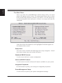
1
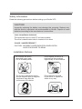
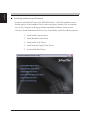
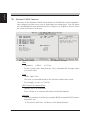
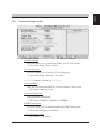
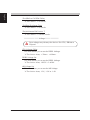
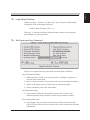
XPC User Guide For the : SA76 Shuttle® XPC Installation Guide Copyright ©2009 by Shuttle® Inc. All Rights Reserved. No part of this publication may be reproduced, transcribed, stored in a retrieval system, translated into any language, or transmitted in any form or by any means such as electronic, mechanical, magnetic, optical, chemical, photocopy, manual, or otherwise, without prior written permission from Shuttle® Inc. Other brands and product names used herein are for identification purposes only and may be trademarks of their respective owners. Disclaimer Shuttle® Inc. shall not be liable for any incidental or consequential damages resulting from the performance or use of this product. Shuttle® Inc. makes no representation or warranty regarding the contents of this manual. Information in this manual had been carefully checked for accuracy;however, no guarantee is given as to the correctness of the contents. For continuing product improvement, Shuttle® Inc. reserves the right to revise the manual or make changes to the specifications of this product at any time without notice and obligation to any person or entity regarding such change. The information contained in this manual is provided for general use by customers. This device complies to Part 15 of the FCC Rules. Operation is subject to the following two conditions: 1.This device may not cause harmful interference. 2.This device must withstand any background interference including those that may cause undesired operation. Trademarks Shuttle is a registered trademark of Shuttle Inc. Intel and Pentium are registered trademarks of Intel Corporation. PS/2 is a registered trademark of IBM Corporation. AWARD is a registered trademark of Award Software Inc. Microsoft and Windows are registered trademarks of Microsoft Corporation. General Notice Other brand and product names used herein are for identification purposes only and may be trademarks of their respective owners. Safety Information Read the following precautions before setting up a Shuttle XPC. CAUTION Incorrectly replacing the battery may damage this computer. Replace only with the same or equivalent as recommended by Shuttle. Dispose of used batteries according to the manufacturer's instructions. Laser compliance statement The optical disc drive in this PC is a laser product. The drive's classification label is located on the drive. CLASS 1 LASER PRODUCT CAUTION:INVISIBLE LASER RADIATION WHEN OPEN. AVOID EXPOSURE TO BEAM. Installation Notices Do not place this device underneath heavy loads or in an unstable position. Do not use or expose this device around magnetic fields as magnetic interference may affect the performance of the device. Do not expose this device to high levels of direct sunlight, high-humidity or wet conditions. Do not block the air vents to this device or impede the airflow in any way. TABLE OF CONTENTS Driver and Software Installation...................................................................................1 Mainboard Driver CD ..............................................................................................1 Install Mainboard Software ..............................................................................2 Appendix......................................................................................................................3 Enter the BIOS.........................................................................................................3 The Main Menu........................................................................................................4 Standard CMOS Features ...............................................................................4 Advanced BIOS Features . ..............................................................................6 Advanced Chipset Features.............................................................................9 Integrated Peripherals ..................................................................................12 Power Management Setup ............................................................................15 PnP/PCI Configurations ............................................................................... 17 PC Health Status ...........................................................................................18 Frequency/Voltage Control ............................................................................19 Load Default Settings.....................................................................................21 Set Supervisor/User Password .....................................................................21 Save & Exit Setup .........................................................................................22 Exit Without Saving .......................................................................................22 English Driver and Software Installation Motherboard Driver DVD Note : The DVD contents attached in SA76 motherboard are subject to change without notice. The product's specifications will depend upon the actually shipping product. The Motherboard Driver DVD contains all the motherboard drivers necessary to optimize the performance of this XPC in a Windows® OS. Install these drivers after installing Microsoft® Windows®. Navigation Bar Description : Install Motherboard Drivers - Install AMD Chipset Driver, Install Realtek Audio Driver, Install AMD VGA Driver, Install Marvell Gigabit LAN Driver, Install AMD Raid Driver. Install Utilities - Install Adobe Reader, Install Norton Internet Security software. User Manuals -SA76 Manual/SA76 Quick Guide in PDF format. Link to Shuttle Website - Link to shuttle website homepage. Browse this DVD - Allows you to see contents of this DVD. English Installing Motherboard Software Insert the attached DVD into your DVD-ROM drive. The DVD AutoRun screen should appear. If the AutoRun screen does not appear, double click on Autorun icon in My Computer to bring up Shuttle Mainboard Software Setup screen. Click the “Install Motherboard Drivers“ bar. Individually install the following drivers. Install AMD Chipset Driver Install Realtek Audio Driver Install AMD VGA Driver Install Marvell Gigabit LAN Driver Install AMD Raid Driver English Appendix BIOS Settings The SA76 BIOS ROM has a built-in Setup program that allows users to modify basic system configuration. This information is stored in battery-backed RAM so that it retains Setup information even if the system power is turned off. The system BIOS manages and executes variety of hardware related functions including: System date and time Hardware execution sequence Power management functions Allocation of system resources Enter the BIOS To enter the BIOS (Basic Input / Output System) utility, follow these steps: Step1. Power on the computer. The system will perform its POST (Power-On Self Test) routine checks. Step2. Press the <Del> key immediately, or at the following message: Press DEL to enter SETUP, or simultaneously press <Ctrl>,<Alt>, <Esc> keys 1. If you miss wordings mentioned in step2 (the message disappears before you can respond) and you still wish to enter BIOS Setup, restart the system and try again by turning the computer OFF and ON again or by pressing the <RESET> switch located at the computer’s front-panel. You may also reboot by simultaneously pressing the <Ctrl>,<Alt>, <Del> keys simultaneously. 2. If you do not press the keys in time and system does not boot, the screen will prompt an error message, and you will be given the following options: Step3. "Press F1 to Continue, DEL to Enter Setup” When you enter the BIOS program, the CMOS Setup Utility will display the Main Menu, as shown in the next section. English The Main Menu Once you enter the AwardBIOS(tm) CMOS Setup Utility, the Main Menu will appear on the screen. The Main Menu allows you to select from several setup functions and two exit choices. Use the arrow keys to select among the items and press <Enter> to accept and enter the sub-menu. Note that a brief description of each highlighted selection appears at the bottom of the screen. Setup Items The main menu includes the following main setup categories. Recall that some systems may not include all entries. Standard CMOS Features Use this menu for basic system configuration. Advanced BIOS Features Use this menu to set the Advanced Features available on your system. Integrated Peripherals Use this menu to specify your settings for integrated peripherals. Power Management Setup Use this menu to specify your power management settings. English PnP / PCI Configurations This entry appears if your system supports PnP / PCI. PC Health Status This entry displays the current system temperature, Voltage, and FAN settings. Frequency/Voltage Control Use this menu to specify your settings for frequency/voltage control. Load Default Settings Use this menu to load the BIOS default values that are factory-set for optimal system operation. While Award has designed the custom BIOS to maximize performance, the factory has the right to change these defaults to meet users' needs. Set Supervisor / User Password Use this menu to change, set, or disable password protection. This allows you to limit access to the system and Setup, or only to Setup. Save & Exit Setup Save CMOS value changes in CMOS and exit from setup. Exit Without Saving Abandon all CMOS value changes and exit from setup. English Standard CMOS Features The items in the Standard CMOS Setup Menu are divided into several categories. Each category includes none, one or more than one setup items. Use the arrow keys to highlight the item and then use the <PgUp> or <PgDn> keys to select the value you want in each item. Date <Month> <DD> <YYYY> Set the system date. Note that the 'Day' automatically changes when you set the date. Time <HH : MM : SS> The time is converted based on the 24-hour military-time clock. For example, 5 p.m. is 17:00:00. IDE Channel 0/1 Master/Slave Options are in its sub-menu. Press <Enter> to enter the sub-menu of detailed options. Halt On Select the situation in which you want the BIOS to stop the POST process and notify you. The choice:All Errors, No Errors or All, But Keyboard. English Base/Extended/Total Memory Theseitems are automatically detected by the system at start up time. These are display-only fields. You can't make change to these fields. ****************************************************** IDE Adapters The IDE adapters control the hard disk drive. Use a separate sub-menu to configure each hard disk drive. IDE HDD Auto-Detection Press <Enter> to auto-detect HDD on this channel. If detection is successful, it fills the remaining fields on this menu. Press Enter IDE Channel 0/1 Master/Slave Selecting 'manual' lets you set the remaining fields on this screen and select the type of fixed disk. "User Type" will let you select the number of cylinders, heads, etc., Note: PRECOMP=65535 means NONE ! The choice: None, Auto, or Manual. Access Mode Choose the access mode for this hard disk. The choice: CHS, LBA, Large, or Auto. Capacity Disk drive capacity (Approximated). Note that this size is usually slightly greater than the size of a formatted disk given by a disk checking program. Auto-Display your disk drive size. The following options are selectable only if the 'IDE Primary Master' item is set to 'Manual', and Access mode set to CHS. English Cylinder Set the number of cylinders for this hard disk. Min = 0, Max = 65535 Head Set the number of read/write heads. Min = 0, Max = 255 Precomp Warning: Setting a value of 65535 means no hard disk. Min = 0, Max = 65535 Landing zone Set the Landing zone size. Min = 0, Max = 65535 Sector Number of sector per track. Min = 0, Max = 255 ****************************************************** English Advanced BIOS Features This section allows you to configure your system for basic operation. You have the opportunity to select the system's default speed, boot-up sequence, keyboard operation, shadowing, and security. CPU Feature Options are in its sub-menu. Press <Enter> to enter the sub-menu of detailed options. AMD Cool&Quiet control This item allows you to set the AMD Cool&Quiet control. The choice: Auto or Disabled. Hard Disk Boot Priority This item allows you to select Hard Disk Book Device Priority. Bios Write Protect This item allows you to enable or disable the Bios Write Protect. If you want to flash BIOS, you must set it [Disabled]. The choice: Enabled or Disabled. Virus Warning Allows you to choose the VIRUS Warning feature for IDE Hard Disk boot sector protection. If this function is enables and someone attempts to write data into this area, BIOS will show a warning message on screen, and an alarm beep. English Enabled Activates automatically when the system boots up,causing a warning message to appear when anything attempts to access the boot sector or hard disk partition table. Disabled No warning message will appear when anything attempts to access the boot sector or hard disk partition table. The choice: Enabled or Disabled. Quick Power On Self Test This item speeds up Power-On Self Test (POST) after you power on the computer. If it is set to enabled, BIOS will shorten or skip some check items during POST. The choice: Enabled or Disabled. First/Second/Third Boot Device The BIOS attempts to load the operating system from the devices in the sequence selected in these items. The Choice:LS120, Hard Disk, CDROM, ZIP100, USB-FDD, USB-ZIP, USB-CDROM or Disabled. Boot Up Floppy Seek Enabled tests floppy drives to determine whether they have 40 or 80 tracks. The choice: Enabled or Disabled. Security Option Select whether the password is required every time the system boots or only when you enter setup. System The system will not boot and access to Setup will be denied if the correct password is not entered promptly. Setup The system will boot, but access to Setup will be denied if the correct password is not entered promptly. The choice: System or Setup. To disabled security, select PASSWORD SETTING at Main Menu, and then you will be asked to enter password. Don't type anything and just press <Enter>; it will disable security. Once the security is disabled, the system will boot, and you can enter Setup freely. 10 English HDD Security Freeze Lock This item allows you to enable/disable the HDD Security Freeze Lock. Enabled - prevents any external application from locking Hard drive except for BIOS. The choice: Enabled or Disabled. Delay For HDD <Secs> This item allows you to set delay for HDD<secs>. The choice: 0~15. Full Screen LOGO Show This item allows you to enable/disable the Full Screen LOGO Show. The choice: Enabled or Disabled. 11 English Integrated Peripherals On-Chip SATA Device Option are in its sub-menu. Press<Enter>to enter the sub-menu of detailed options. OnChip SATA Channel This item allows you to enable or disable the SATA Controller. The Choice: Enabled or Disabled. OnChip SATA Type This item allows you to set the OnChip SATA Type. The choice: RAID, AHCI, Legacy IDE or Native IDE. Not support RAID 10 function in RAID mode. Onboard Devices Option are in its sub-menu. Press<Enter>to enter the sub-menu of detailed options. IGX Configuration Option are in its sub-menu. Press<Enter>to enter the sub-menu of detailed options. Internal Graphics Mode This item allows you to set the Internal Graphics Mode. The Choice: UMA or Disabled. 12 English UMA Frame Buffer Size This item allows you to set the UMA Frame Buffer Size. The Choice: 32MB, 64MB, 128MB, 256MB or 512MB. Surround View This item allows you to set the Surround View. The Choice: Auto, Disabled or Enabled. High Definition Audio This item allows you to set the High Definition Audio. The choice: Enabled or Disabled. Onboard LAN Function Decide whether to invoke the onboard LAN chip. The choice: Enabled or Disabled. Onboard Lan Boot ROM Decide whether to invoke the boot ROM of the onboard LAN chip. The choice: Disabled or Enabled. SuperIO Device Option are in its sub-menu. Press<Enter>to enter the sub-menu of detailed options. Onboard Serial Port 1/2 This option is used to assign the I/O address and interrupt request ( IRQ ) for the onboard serial port 1/2. The choice:Disabled, 3F8/IRQ4, 2F8/IRQ3, 3E8/IRQ4, 2E8/IRQ3. Onboard Parallel Port This item allows you to determine onboard parallel port controller I/O address and interrupt request ( IRQ ). The choice: 378/IRQ7, 278/IRQ5, 3BC/IRQ7, or Disabled. Parallel Port Mode Select an operating mode for the onboard parallel (printer) port. Select Normal, Compatible, or SPP unless you are certain your hardware and software both support one of the other available modes. The choice: SPP, EPP, ECP, or ECP+EPP. 13 English CIR Function This item allows you to set the CIR Function. The choice: Enabled, or Disabled. USB Device Setting Option are in its sub-menu. Press<Enter>to enter the sub-menu of detailed options. USB 2.0 Controller Enable or Disable Universal Host Controller Interfacefor Universal Serial Bus. The choice: Enabled or Disabled. USB Operation Mode Auto decide USB device operation mode. High speed:If USB device was high speed device, then it operated on high speed mode.If USB device was full/low speed device, then it operated on full/low speed mode. Full/Low Speed:All of USB device operated on full/low speed mode. The choice: High speed or Full/Low Speed. USB Storage Function Enable or Disable Legacy support of USB USB Mass Storage. The choice: Enabled or Disabled. *** USB Mass Storage Device Boot Setting *** UFDDA USB Floppy UFDDB USB Floppy No Device Auto: According to contents of USB MSD decide boot up type. FDD Mode: The USB MSD always boot up as floppy disk. HDD Mode: The USB MSD always boot up as hard disk. The choice: Auto mode, FDD mode or HDD mode. 14 English Power Management Setup The Power Management Setup allows you to configure your system to most effectively saving energy while operating in a manner consistent with your own style of computer use. ACPI Function This item allows you to enable/disable the Advanced Configuration and Power Management (ACPI). Always "Enabled". ACPI Suspend Type This item allows you to select sleep state when suspend. The choice: S1(POS) or S3(STR). Wake-Up by PCI card This item allows you to set the Wake-Up by PCI card. The choice: Disabled or Enabled. Wake-Up by Ring This item determine the system will resume by activating of modem ring. The choice: Disabled or Enabled. Resume by Alarm When this item enabled, your can set the date (day of the month) and time to turn on your system. The choice: Disabled or Enabled. 15 English Date(of Month) Alarm This item selects the alarm Date (day of the month). Key in a DEC number: Min=0, Max=31. Time(hh : mm : ss) Alarm This item selects the alarm Time. [hh] Key in a DEC number: Min=0, Max=23. [mm/ss]Key in a DEC number: Min=0, Max=59. Power on By PS2 Keyboard This item allows you to set the Keyboard Power On function. Only supports S4/S5. The choice: Disabled, password, Hot KEY, Any KEY. KB Power ON Password This item allows you to set the KB Power On Password. Press" Enter" to set Password. Hot Key Power On This item allows you to set the Hot Key Power On. The choice: Ctrl-F1~Ctrl-F12. PWR-On After PWR-Fail This item defines if the system will be rebooted after the power fails. The choice: Off, On. 16 English PnP/PCI Configurations This section describes the configuration of PCI bus system. PCI or Personal Computer Interconnection is a system which allows I/O devices to operate at the speed CPU itself keeps when CPU communicating with its own special components. This section covers some very technical items, and it is strongly recom-mended that only experienced users should make any changes to the default settings. Init Display First This item is used to determine initial device when system power on. The choice: PCI Slot, Onboard or PCI Ex. Resource Controlled By The Award Plug-and-Play BIOS has the capacity to automatically configure all of the boot and Plug-and-Play compatible devices. However, this capability means absolutely nothing unless you are using a Plug-and-Play operating system such as Windows 95. The choice: Auto(ESCD) or Manual. IRQ3/4/5/7/10/11/12/14/15 assigned This item allows you to determine the IRQ assigned to the ISA bus and is not available to any PCI slot. Legacy ISA for devices is compliant with the original PC AT bus specification; PCI/ISA PnP for devices is compliant with the Plug-and-Play standard whether designed for PCI or ISA bus architecture. The choice: PCI Device or Reserved. PCI/VGA Palette Snoop It determines whether the MPEG ISA/VESA VGA Cards can work with PCI/VGA or not. If you have MPEG ISA/VESA VGA Cards and PCI/VGA Card worked, Enable this field. Otherwise, please Disable it. The choice: Enabled or Disabled. 17 English PC Health Status CPU Fan Speed Control Here you can set the CPU Fan Speed. The choice:Smart Fan Mode, Ultra-Low Speed, Low Speed, Mid Speed, or Full Speed. CPU Voltage +5V +3.3V +12V DDR2 Voltage ChipSet Voltage +5VSB Voltage Battery System Temperature CPU Temperature Fan 2 - Chipset Fan Fan 1 - CPU Fan 18 Before manually modifying the CPU fan setting, please make sure fan connectors are plug ged into the correct fan conne ctor on the motherboard. Warning:It is strongly recommended to disable 'Smart Fan' if you use an alternative fan to the default. English Frequency/Voltage Control HT Link Width This item allows you to enable or disable the HT Link Width. The choice: Auto, 8 bit or 16 bit. HT Link Frequency This item allows you to set the HT Link Frequency. The choice: Auto, 200 MHz~2.6 GHz. ******** Memory Timing Set ********* Timing Mode Auto, no user limit MaxMemClk, limit by Memory Clock value. The Choice: Manual or Auto. Memory Clock Value Setting platform Memclock. The Choice: DDR533, DDR667 or DDR800. DDRII Timing Item This item allows you to enable/disable the DDRII Timing Item. The choice: Enabled or Disabled. (Tcl)CAS Latency Time The Choice: 3~6 clocks. 19 English (Trcd)RAS to CAS R/W Delay The Choice: 3~6 clocks. (Trp)Row Precharge Time The Choice: 3~6 clocks. (Tras)Minimum RAS Active T The Choice: 5~18 bus clocks. ************** Voltage ************* Over voltage may destroy the devices like CPU, DRAM or Chipset!! CPU Voltage Offset This item allows you to set the DDR2 Voltage. The choice: Auto, +50mv~+400mv. DDR2 Voltage Set This item allows you to set the DDR2 Voltage. The choice: Auto, 1.825V~2.400V. NB Voltage Set This item allows you to set the NB Voltage. The choice: Auto, 1.2V, 1.3V or 1.4V. 20 English Load Default Settings When you press <Enter> on this item, you will get a confirmation dialog box with a message similar to: Load Default Settings (Y/N) ? N Pressing 'Y' loads the default values that are factory-set for optimal performance system operation. Set Supervisor/User Password Steps to set supervisor/user password are described as follows: New Password Setting: 1. While pressing <Enter> to set a password, a dialog box appears to ask you enter a password. 2. Key in a new password. The password can not exceed eight characters. 3. System will request you to confirm the new password again. 4. When completed, new code takes effect. No Password Setting: 5. If you want to delete the password, just press the <Enter> key instead of typinga new password. Follow the procedure as ablve. If You Forget Password: 6. If you forget your password, you must turn off the system and clear CMOS. Please refer to the tech notes at the end of section two for more information. 21 English Save & Exit Setup Pressing <Enter> on this item asks for confirmation: SAVE to CMOS and EXIT (Y/N)? Y Pressing "Y" stores the selections made in the menus of CMOS - a special section of memory that stays on after you turn your system off. The next time you boot your computer, the BIOS configures your system according to the Setup selections stored in CMOS. After saving the values the system is restarted again. Exit Without Saving Pressing <Enter> on this item asks for confirmation: Quit Without Saving (Y/N)? N This allows you to exit from Setup without storing in CMOS any change. The previous selections remain in effect. This exits from the Setup utility and restarts your computer. 22