1
User's Manual
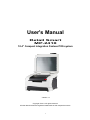
Retail Smart
MP-2410
10.4” Compact Integration Fanless POS system
Version 1.0
Copyright © 2011. All rights reserved.
All other brand names are registered trademarks of their respective owners.
1
Copyright Notice
This document is copyrighted, © 2011. All rights are reserved. FIRICH ENTERPRISES
CO., LTD. has the right to make improvements of the product described in this manual at
any time without notice.
No part of this manual may be reproduced, copied, translated, or transmitted in any form
or by any means without the prior written permission from FIRICH ENTERPRISES CO.,
LTD.. Information provided in this manual is intended to be accurate and reliable. However,
FIRICH ENTERPRISES CO., LTD. assumes no responsibility for its use, nor for any
infringements upon the rights of third parties, which may result from its use.
The material in this document is for product information only and is subject to change
without notice. While reasonable efforts have been made in the preparation of this
document to assure its accuracy, FIRICH ENTERPRISES CO., LTD., assumes no
liabilities resulting from errors or omissions in this document, or from the use of the
information contained herein.
The software described in this guide is furnished under a license agreement or
nondisclosure agreement. The software may be used or copied only in accordance with
the terms of the agreement.
Product names mentioned herein may be trademarks and/or registered trademarks of
their respective companies.
First Edition Nov. 2011
2
Safety and Warranty
1.
Read these safety instructions carefully.
2.
Keep this user's manual for later reference.
3.
Disconnect this equipment from any AC outlet before cleaning. Do not use liquid or spray
detergents for cleaning. Use a damp cloth.
4.
For pluggable equipment, the power outlet must be installed near the equipment and must be
easily accessible.
5.
Keep this equipment away from humidity.
6.
Put this equipment on a reliable surface during installation. Dropping it or letting it fall could
cause damage.
7.
The openings on the enclosure are for air convection. Protect the equipment from
overheating. DO NOT COVER THE OPENINGS.
8.
Retail Smart (MP2410) applies 24V 120W/180W DC Power Adaptor. Make sure the voltage
of the power source is correct before connecting the equipment to the power outlet.
9.
Position the power cord so that people cannot step on it. Do not place anything over the
power cord.
10. All cautions and warnings on the equipment should be noted.
11. If the equipment is not used for a long time, disconnect it from the power source to avoid
damage by transient over-voltage.
12. Never pour any liquid into an opening. This could cause fire or electrical shock.
13. Never open the equipment. For safety reasons, only qualified service personnel should open
the equipment.
14. If any of the following situations arises, get the equipment checked by service personnel :
a.
b.
c.
d.
e.
f.
The power cord or plug is damaged.
Liquid has penetrated into the equipment.
The equipment has been exposed to moisture.
The equipment does not work well, or you cannot get it to work according to the user
manual.
The equipment has been dropped and damaged.
The equipment has obvious signs of breakage.
15. DO NOT LEAVE THIS EQUIPMENT IN AN UNCONTROLLED ENVIRONMENT WHERE
THE STORAGE TEMPERATURE IS BELOW -20° C (-4°F) OR ABOVE 60° C (140° F). IT
MAY DAMAGE THE EQUIPME
3
Table of Content
About this Manual
9
Chapter1
10
Introduction
10
Retail Smart Characteristics…………………………………………………………………………...
10
A Quick Tour of Retail Smart…………………………………………………………………………12
Chapter2
16
Hardware Setup
16
Retail Smart Power On………………………………………………………………………………..16
2.5” Hard Disk Drive (SSD) Installation…………………………………………………………….. 17
Memory (DDRII) , DOM Installation. ……………………………………………………………….. 19
Compact Flash Installation & COM port Jumper Selection………………………………………. 20
Magnetic Card Reader Installation………………………………………………………………….. 21
Integrated LCM Installation…………………………………………………………………………...23
Second Display Installation………………………………………………………………………….. 24
Cash Drawer Installation……………………………………………………………………………... 25
Chapter3
27
Software Installation
27
Driver Download from FEC Website………………………………………………………………... 27
Please follow this installation sequence accordingly……………………………………………… 27
Intel Chipset Driver Installation for Windows XP…………………………………………………...28
VGA Driver Installation……………………………………………………………………………….. 30
Audio Driver Installation……………………………………………………………………………… 32
Lan Driver Installation………………………………………………………………………………… 34
EETI Touch Tools Installation……………………………………………………………………….. 36
Chapter 4
40
Specifications
40
Retail Smart Specifications...…………………………………………………………………………40
Thermal Printer Specifications………………………………………………………………………. 41
Retail Smart Block Diagram Definition……………………………………………………………… 42
Chapter5
43
Troubleshooting
43
Touch Panel does not Work…………………………………………………………………………. 43
Touch Panel Cannot Calibrate Correctly…………………………………………………………… 43
LCD Panel is Not Functioning Properly…………………………………………………………….. 43
MCR is not functioning properly……………………………………………………………………...43
VFD/LCM Pole Display is not functioning properly………………………………………………... 44
LAN is not functioning properly……………………………………………………………………… 44
4
Printer functionality…………………………………………………………………………………….44
Chapter6
45
Appendix Thermal Printer RS-T80
45
User Manual
45
1 Introduction
50
1.1 Outline
1.2 Main Features
50
50
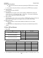
2 Main Specification
51
2.1 Technical Specification
51
2.2 Cutter Specification
52
2.3 Paper Specification
52
2.3.1 Continuous paper ....................................................................................................... 52
2.3.2 Marked paper ............................................................................................................. 52
2.4 Print and cut position
53
2.4.1 Print position ............................................................................................................... 53
2.4.2 Cut position ................................................................................................................. 54
3 Outline and Parts
55
3.1 Outline and Parts
3.2 Error LED and Buzzers
55
56
4 Installation
57
4.1 Unpacking
57
4.2 Printer installation
57
4.3 Connecting the Power Adapter
57
4.4 Connecting interface cable
58
4.5 Connecting the Cash Drawer
58
4.6 Paper roll loading
59
4.6.1 Confirm the paper type ............................................................................................... 59
4.6.2 Load/replace a paper roll ............................................................................................ 59
4.7 Paper near end position adjustment
60
4.8 Switching on the printer and printing of self-test
60
4.8.1 Switching on the printer .............................................................................................. 60
4.8.2 Printing a self-test page .............................................................................................. 60
4.9 Setting of printer parameters and configuration
61
5 Printer routine maintenance
62
5.1 Cleaning the platen
5.2 Cleaning the mark sensors
5.3 Clearing of a paper jam
62
62
62
6 Interface signal
63
6.1 Parallel interface
6.2 Serial interface
6.3 USB interface
6.4 Ethernet interface
63
64
64
65
5
6.5 WLAN interface
6.6 Signal definition of power connector
6.7 Signal definition of cash drawer interface
7 Troubleshooting
68
7.1 Printer doesn’t work
7.2 Alarm LED and buzzer sound
7.3 Problems with printing
7.4 Cutter resetting
Chapter
65
67
67
68
68
68
68
1
69
Appendix (B) – Thermal Printer RS-T80
69
Programming Manual
69
1 Overview
74
1.1 Commands classification
1.2 Key terms
1.3 Command format
74
74
75
2 Command Description
76
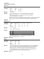
2.1 Print command
76
LF ........................................................................................................................................ 76
FF ........................................................................................................................................ 76
CR ....................................................................................................................................... 76
ESC FF ................................................................................................................................ 76
ESC J n ............................................................................................................................... 77
ESC d n ............................................................................................................................... 77
2.2 Location command
78
HT ........................................................................................................................................ 78
ESC $ nL nH ........................................................................................................................ 79
ESC D n1...nk NUL .............................................................................................................. 80
ESC T n ............................................................................................................................... 80
ESC W xL xH yL yH dxL dxH dyL dyH ................................................................................ 82
ESC \ nL nH ......................................................................................................................... 84
ESC a n ............................................................................................................................... 85
GS $ nL nH .......................................................................................................................... 86
GS L nL nH .......................................................................................................................... 86
GS P x y .............................................................................................................................. 87
GS W nL nH ........................................................................................................................ 88
GS \ nL nH ........................................................................................................................... 89
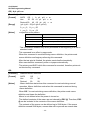
2.3 Character command
89
CAN ..................................................................................................................................... 89
ESC SP n ............................................................................................................................ 90
ESC ! n ................................................................................................................................ 91
ESC % n .............................................................................................................................. 94
ESC & y c1 c2 [x1 d1...d(y × x1)]...[xk d1...d(y × xk)] .......................................................... 94
ESC – n ............................................................................................................................... 96
ESC ? n ............................................................................................................................... 97
6
ESC E n ............................................................................................................................... 97
ESC G n .............................................................................................................................. 98
ESC M n .............................................................................................................................. 98
ESC R n ............................................................................................................................... 99
ESC V n ............................................................................................................................... 99
ESC t n .............................................................................................................................. 100
ESC { n .............................................................................................................................. 100
GS ! n ................................................................................................................................ 101
GS B n ............................................................................................................................... 102
FS ! n ................................................................................................................................. 103
FS & ................................................................................................................................... 104
FS - n ................................................................................................................................. 104
FS . .................................................................................................................................... 105
FS 2 c1 c2 d1...dk .............................................................................................................. 105
FS S n1 n2 ......................................................................................................................... 106
FS W n ............................................................................................................................... 107
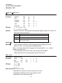
2.4 Bitmap Command
107
ESC * m nL nH d1... dk ..................................................................................................... 107
ESC # n ............................................................................................................................. 109
GS * x y d1...d(x × y × 8) ................................................................................................... 109
GS / m ............................................................................................................................... 110
GS v 0 m xL xH yL yH d1....dk .......................................................................................... 111
FS p n m ............................................................................................................................ 112
FS q n [xL xH yL yH d1...dk]1...[xL xH yL yH d1...dk]n ...................................................... 112
DLE EOT n ........................................................................................................................ 115
GS a n ............................................................................................................................... 116
GS r n ................................................................................................................................ 118
2.6 Barcode command
119
GS H n ............................................................................................................................... 119
GS f n ................................................................................................................................ 119
GS h n ............................................................................................................................... 120
①GS k m d1...dk NUL②GS k m n d1...dn......................................................................... 120
GS p n ............................................................................................................................... 124
GS q n ............................................................................................................................... 124
GS w n ............................................................................................................................... 125
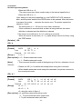
2.7 Other commands
125
DLE ENQ n ........................................................................................................................ 125
DLE DC4 n m t .................................................................................................................. 126
ESC 2 ................................................................................................................................ 126
ESC 3 n ............................................................................................................................. 127
ESC = n ............................................................................................................................. 127
ESC @............................................................................................................................... 129
ESC L ................................................................................................................................ 129
ESC S ................................................................................................................................ 129
ESC c 0 n .......................................................................................................................... 131
ESC c 3 n .......................................................................................................................... 131
ESC c 4 n .......................................................................................................................... 133
7
ESC c 5 n .......................................................................................................................... 134
ESC p m t1 t2 .................................................................................................................... 134
GS FF ................................................................................................................................ 134
GS ( A pL pH n m .............................................................................................................. 135
GS : ................................................................................................................................... 135
①GS V m ②GS V m n ..................................................................................................... 136
GS ^ r t m........................................................................................................................... 136
GS { w ................................................................................................................................ 137
GS { w f .............................................................................................................................. 137
3 Programming Process Guide
140
Appendix
141
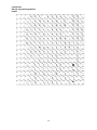
Appendix A: Code128 Bar Code
141
Appendix B: Print mode and its change
144
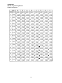
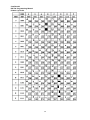
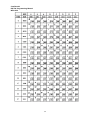
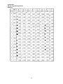
Appendix C: Control Sequences & Code Page Fonts
149
PC437: USA ...................................................................................................................... 151
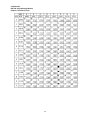
PC850: Multilingual ......................................................................................................... 152
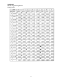
PC852 Latin2 .................................................................................................................... 153
PC858 ................................................................................................................................ 154
PC860: Portuguese .......................................................................................................... 155
PC863: Canadian-French ................................................................................................ 156
PC865: Nordic .................................................................................................................. 157
PC866: Cyrillic #2 ............................................................................................................ 158
Katakana ........................................................................................................................... 160
International Fonts .......................................................................................................... 161
8
About this Manual
This manual contains all the information you need to set up and use Retail Smart.
Chapter 1
Provides an introduction to Retail Smart and this manual.
Chapter 2
Provides all necessary information for all hardware setup.
Chapter 3
Provides the necessary information for installing for chipset and its accessories.
Chapter 4
Lists all Retail Smart specifications include optional second I/O.
Chapter 5
Troubleshooting of Retail Smart
9
CHAPTER1
Introduction
Retail Smart Characteristics
Retail Smart is a dual core mobile POS and all-in-one fan-less POS system
of FIRICH ENTERPRISES CO., LTD. The extensible, robust and fan-less
design makes it a perfect solution for retail and hospitality market.
System: A high speed fan-less processor enables to process a high capacity of data
efficiently.
Housing: The solid aluminum housing dissipates the heat inside the system and makes
it a perfect fan-less solution; additionally it also assures the compliance to EMI radiation
testing.
Compact: Integrated with different peripherals
Display: The LCD display can be tilted at multiple angles for operator ease of use.
Extensibility: There are five optional second I/O that customer can choose by their
requirement. In addition to, the VESA mount can be others transforming of this system.
10
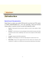
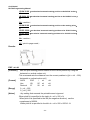
Retail Smart With
Thermal Printer
Retail Smart with LCM
11
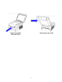
A Quick Tour of Retail Smart
10.4” Touch
IC Card
3.5” Thermal
Printer
MSR Reader
2.5” HDD Tray
System LED
Status
Receipt
Paper Out
Printer Cover
Opening Lifter
12
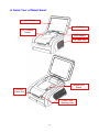
LCM
Customer Display
Printer Power
Hidden USB Ports
Rear I/O
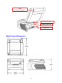
Retail Smart Dimension
13
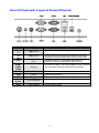
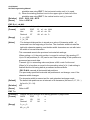
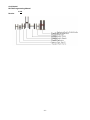
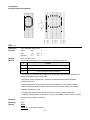
Rear I/O Panel (with 5 types of Second IO board)
I/O Port
Connector Type
24V DC-In
12V DC-Out
PS/2
COM 1
COM 2
COM 4
VGA
LAN
USB
Cash
Drawer
Power
PS/2
D-sub 9
D-Sub15
RJ-45
USB type A
RJ11 connector
Power Switch
Description
Connect the 24V power adaptor to this port
This DC-out port can power the monitor or any other
peripheral or device which need 12V DC power input.
Supports general Programmable Key Board, PC
KeyBoard, Mouse or standalone MSR devices
The RS-232 COM 1, 2 & 4 can support RI / 5V / 12V and
also be used to connect peripherals and devices.
The VGA port is used for connecting the 2nd monitors
GigaLAN to Ethernet
Standard USB connector for external device
Cash Drawer Connector, 12 V actuation support
System power switch
14
Packaging List
Retail Smart Main System and pedestal integrated with 24V-120w Power adaptor
AC power cord
24V DC 12W Power Adaptor
15
CHAPTER2
Hardware Setup
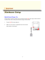
Retail Smart Power On
Please make sure that the system power is turned off and the 24V power supply is disconnected to
the Retail Smart when making any hardware changes to Retail Smart.
1.
Plug the 24V DC power adaptor in
2.
Make sure every device or peripherals are well connected
before switch on the System.
16
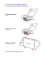
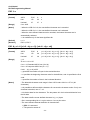
2.5” Hard Disk Drive (SSD) Installation
1. Turn off power and remove power cord from the system
2. Unscrew the maintenance
door at the rear side of the
unit
3. Remove the HDD Tray and
take it off
4. Remove the screws from
the both sides of HDD
2.5” HDD
5. Restore the HDD Tray to back to the system.
17
6. Fix the HDD Tray with the screw.
18
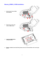
Memory (DDRII) , DOM Installation
1.
Unscrew and remove Main
Board Module
2.
lift two bars at the both
sides of MB module
3.
Install the DDRII RAM or
CPU you require
4.
Restore the Main board Unit Back (please ensure the Thermal Pad is still on the right
place)
19
Compact Flash Installation & COM port Jumper Selection
1.
Unscrew and remove the
maintenance bracket
2.
Slot the CF in
3.
Select jumper setting for
RS-232 powered options;
please follow the
instruction on the back
side of bracket
4.
According to the COM
port setting, please refer
to the M/B manual
5.
Install the CF you require or selected the proper RS-232 jumper settings
6.
Restore the maintenance bracket
20
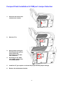
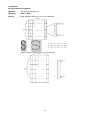
Magnetic Card Reader Installation
1. Turn off power and remove power cord from the system
2. Unscrew the 2 screws of
front panel
3. Make Sure the LCM Cover
is removed
4. Remove Back Cover of
Display
5. Prepare a MCR Module
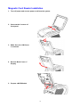
21
6. Fasten 2 Screws and
connect one MSR Cable
(USB interface) with MSR
Module
7. Cover the Back cover back and Fasten 2 screws, and re-install the LCM Cover
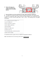
8. This option is for users who need to customize the MCR configurations for a particular task.
To enter the Configuration Mode, please execute text editor program (such as Microsoft Word,
Notepad…etc.) first, and then press [Ctrl] + [Alt] + [F10]. The following menu will appear
accordingly.
For detailed instruction, please refer to the MSR212 Programmer’s Manual
Note: If the MCR does not work normally, please refer to troubleshooting.
22
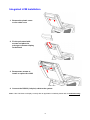
Integrated LCM Installation
1. Remove the plastic cover
on the cable cover
2. Fix the pole stand with
screws and place the
pole-type customer display
to the stand
3. Remove two screws to
install or replace the LCM
4. Connect the RS-232 (1x4 pins) cable to the system.
Note: If the LCM does not display correctly after an application is loaded, please refer to troubleshooting.
23
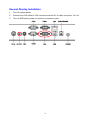
Second Display Installation
1.
Turn off system power.
2.
Connect the VGA cable to VGA connector and the DC in cable connect to 12V out.
3.
Turn on OSD switch power on and turn on system power.
24
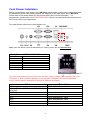
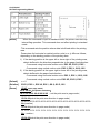
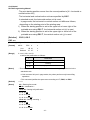
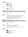
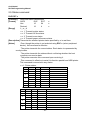
Cash Drawer Installation
Before connecting the cash drawer to the MP-2410, please make sure the drive voltage and cable
pin assignment of the cash drawer matches the definition of the cash drawer port of MP-2410.
Please refer to the mother board (BT-05) manual GPIO part for more information. For
programmers, please refer to the Cash Drawer Driver, where you may find the test programs and
DLL Library files for your application.
Plug cash drawer cable into the cash drawer port.
Note: If the cash drawer cannot be detected by the system, please refer to troubleshooting.
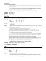
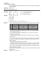
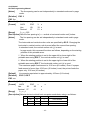
Cash_Drawer1: DIO with RJ-11 Connector
PIN No.
1
2
3
4
5
6
Signal Description
Ground
DIO Out 1
+12V
DIO IN 0
DIO Out 0
Ground
Up to two cash drawers may be driven from this port. Driving voltage of the solenoid is DC+12V.
I/O port 2F is used for drawer operation. A test program is supplied, for Linux and Windows,
source code of which is available on request by software developers.
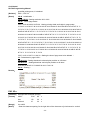
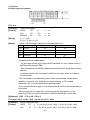
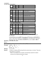
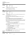
Value
Description
0x01
0x2e,0x87,0x2e,0x87,0x2e,0x07,0x2f,0x09,
0x2e,0xf1
0x2f,0x00
0x2f,0x00
0x53
0x33
0x60
0x80
GPIO:1, DIO:0
Entry commands.
Output address.
Input address.
Open cashdrawer1 value.
Open cashdrawer2 value.
Close cash-drawer value.
Cash-drawer status mask.
25
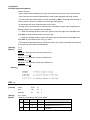
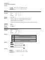
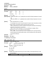
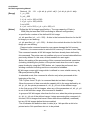
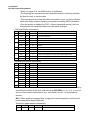
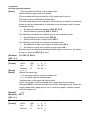
CMOS definition for cash drawer
Test Example:
IO space 0x70 (bank 1).
Reserve IO space in bank2 A0.
0x37 : 0x72
0x38 : 0xA0
Reserve
space.
A0
A1 – B4
B5 – B6
B7 – B8
B9
BA
BB
BC
Value.
Explain.
0x01
0x2e,0x01,0x87,0x01,0x2e,0x01,0x87,0x01,
0x2e,0x01,0x07,0x01,0x2f,0x01,0x09,0x01,
0x2e,0x01,0xf1
0x2f,0x00
0x2f,0x00
0x53
0x33
0x60
0x80
GPIO:1, DIO:0
Entry commands.
Output address.
Input address.
Open cashdrawer1 value.
Open cashdrawer2 value.
Close cash-drawer value.
Cash-drawer status mask.
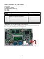
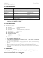
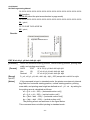
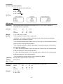
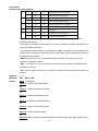
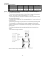
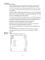
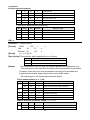
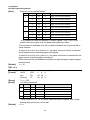
12V / 24V Power Select for cash drawer
Please adjust the jumper setting of MianBoard top side, JP7(as following picture blocked in red)
from (1,2) to (2,3); (1,2) is support 12V; (2,3) is support 24V
3
2
1
26
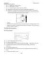
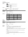
CHAPTER3
Software Installation
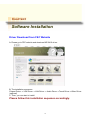
Driver Download from FEC Website
A: Please go to FEC website and download MP-2410 driver.
B: The installation sequence:
Chipset Driver -> VGA Driver -> LAN Driver -> Audio Driver ->Touch Driver ->Other Driver
(optional)
C: Then, you can start to install.
Please follow this installation sequence accordingly.
27
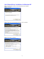
Intel Chipset Driver Installation for Windows XP
Step 1. Please double confirm the Intel chipset driver from website.
Step 2. Click Next
Step 3. Read the License Agreement and click “Yes” to continue
Step 4. Click “Next” to continue
28
Step 5. Click “Next” to continue
Step 6. Click “Finish” to complete setup
29
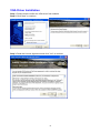
VGA Driver Installation
Step 1. Please double confirm the VGA driver from website
Step 2. Click “Next” to continue
Step 3. Read the License Agreement and click “Yes” to continue
30
Step 4. Click “Next” to continue
Step 5. Click “Next” to continue
Step 6. Click “Finish” to complete setup
31
Audio Driver Installation
Step 1. Please double confirm the Audio driver from website.
Step 2. Click “Next” to continue
Step 3. Double click Setup.exe.
Step 4. Click Next to continue.
32
Step 5. Click Continue to process the installation.
Step 6. Choose YES, click OK to finishing the installation and restart the system.
33
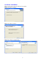
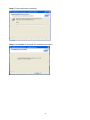
Lan Driver Installation
Step 1. Please double confirm the LAN driver from website.
Step 2. Click “Next” to continue
Step 3. Click “Next” to continue
Step 4. Click “Finish” to complete setup
34
Step 5. Please wait while processing.
Step 6. Click Finish to complete the installation procedure.
35
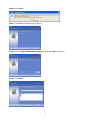
EETI Touch Tools Installation
EETI Touch Tools Installation for Windows XP/ Windows Vista/
Windows 7
Step 1. Locate D:\Utility\TouchScreen\TouchKit\Windows 2000 XP\
Step 2. Select the relevant folder for the operating system that you are using.
Step 3. Open Setup.exe
Step 4. Click Next
Step 5. Click Next
36
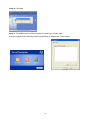
Step 6. Click Next
Step 7. Click OK to close the pop-up dialog.
Step 8. Click “Support Multi-Monitor System” and then Next to continue.
Step 9. Click Next
37
Step 10. Click Yes
Step 11. Click OK and turn off the computer to restart your system again.
After the system finish rebooting follow the directions to calibrate the Touch screen.
38
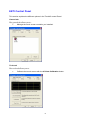
EETI Control Panel
This section explains the different options in the TouchKit control Panel.
General tab
The general tab allows you to:
Manage the touch screen controller you installed.
Tools tab
The tools tab allows you to:
Calibrate the touch screen with the 4 Points Calibration button.
39
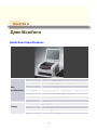
CHAPTER 4
Specifications
Retail Smart Specifications
Main
Specifications
Display
Chipset
Intel 945GSE
/
ICH7M
Processor
Intel®
System Memory
Up to 2GB DDR2 SDRAM on 1 x SODIMM
Power Supply
24V – 120W / 180W Power Adapter
Storage Device
1 x 2.5” SATA
Construction
Aluminum Metal Housing + Plastic Cover
Housing Color
Greece White / Black
LCD Size
10.4” (4:3)
Input Interface
TTL / LVDS
Max Resolution
VGA 800 x 600 / XVGA 1024 x 768
Brightness
300 cd/m² LED Backlight
Atom N270 1.6Ghz
40
Storage (HDD / SDD) / 1 x CFII
Viewing Angle
H160 / V140
Backlight MTBF
10K / 30K hours
Touch Screen
5-Wire Resistive Touch
Speakers
2W x 2
Built-in
MSR
MCR Single / Dual / Triple Track
Components
IC Card Reader
Available USB Interface
LCM
LCM Module (192 x 32 / 20 x 2)
HDD Bay
1 x 2.5” HDD / SSD swappable
Storage Device CF II Slot
1 x CF II Available
SATA DOM
1 x SATA DOM (Optional)
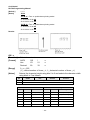
Thermal Printer Specifications
Thermal Printer RS-T80
Thermal head size
Paper Roll capacity
3.5” / 2.5” Thermal Head available
General φ 80mm diameter paper roll
Maximum φ 100mm diameter paper roll
Printer Head Lifetime
>150KM
Optical Sensor
Near End; Paper End; Black Mark
Interface
RS-232
Printing Speed
Maximum 230mm/s
Paper Cut
Tear off, Full cut, Partial cut
Cutter LifeTime
2 million times
Paper load
Easy loading design
Power Consumption
24V DC / Maximum 2.3A
Thermal head size
3.5” / 2.5” Thermal Head available
41
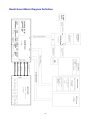
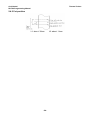
Retail Smart Block Diagram Definition
42
CHAPTER5
Troubleshooting
Please note that the following troubleshooting guide is designed for people with strong computer
hardware knowledge such as System Administrators and Engineers.
Touch Panel does not Work
A)
Check if the touch driver has been properly installed. Or try to reinstall again (Please refer
to the touch driver installation).
B)
Move back cover, check all relative cables for touch controller.
C)
If touch controller does not appear green light, it could be defective.
Touch Panel Cannot Calibrate Correctly
A)
Please try to re-install touch driver and re-calibrate again. If not, the touch controller and
touch panel could be defective.
LCD Panel is Not Functioning Properly
A)
Check that the LCD driver is installed properly (Please refer to the LCD driver installation
section).
B)
Connect a LCD or CRT monitor to the VGA connector, if there is a display, then the LCD
panel could be defective or is not installed properly.
C)
Move back cover, check all the LCD relative cables. (For example: check LVDS, inverter
whether they are properly.)
MCR is not functioning properly
A)
Check if the MCR is properly connected to the MCR connector board on main system.
B)
Make sure the MCR 12PIN cable is properly connected to the right side wafer (which is
USB hub board) of LCD.
C)
The USB hub board could be defective.
D)
The MCR module could be defective.
43
VFD/LCM Pole Display is not functioning properly
A)
Ensure that COM4 is enabled in the CMOS setup, and data is written to COM4 in the
application.
B)
Ensure the jump setting of COM4 ,please refer the M/B manual.
C)
Check if there is any display when system power is ON, if the screen is blank, please
follow the steps below.
B-1)
Make sure the power switch on the VFD display is on before powering the main
system.
D)
Check RJ-45 cable is properly connected to I/O
E)
Check the cable is properly connected to main board
F)
The on-board COM4 I/O chips could be defective.
LAN is not functioning properly
A)
Check if the LAN driver is installed properly. (Please refer to the LAN driver installation)
B)
Check if there are any IRQ conflicts.
C)
Check if the RJ45 cable is properly connected.
D)
The on board LAN chip could be defective.
Printer functionality
A)
Make sure the Printer Power Switch is on before operation
B)
Verify the Connection Cable are well connected
C)
All the command and Code Page, please refer to the Appendix “Printer Manual”
44
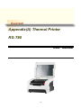
CHAPTER6
Appendix(A) Thermal Printer
RS-T80
User Manual
45
46
Content
General Saf ety Instruct ion
49
1 Int roduct ion
50
1.1 Outline
50
1.2 Main Features
50
2 Main Specif icat ion
51
2.1 Technical Specification
51
2.2 Cutter Specification
52
2.3 Paper Specification
52
2.3.1 Continuous paper ...................................................................................................... 52
2.3.2 Marked paper ............................................................................................................ 52
2.4 Print and cut position
53
2.4.1 Print position ............................................................................................................. 53
2.4.2 Cut position ............................................................................................................... 54
3 Outline and Parts
55
3.1 Outline and Parts
55
3.2 Error LED and Buzzers
56
4 Inst allat ion
57
4.1 Unpacking
57
4.2 Printer installation
57
4.3 Connecting the Power Adapter
57
4.4 Connecting interface cable
58
4.5 Connecting the Cash Drawer
58
4.6 Paper roll loading
59
4.6.1 Confirm the paper type .............................................................................................. 59
4.6.2 Load/replace a paper roll ........................................................................................... 59
4.7 Paper near end position adjustment
60
4.8 Switching on the printer and printing of self-test
60
4.8.1 Switching on the printer ............................................................................................. 60
4.8.2 Printing a self-test page ............................................................................................ 60
4.9 Setting of printer parameters and configuration
61
5 Printe r routine ma int enance
62
5.1 Cleaning the platen
62
5.2 Cleaning the mark sensors
62
5.3 Clearing of a paper jam
62
6 Interface signal
63
6.1 Parallel interface
63
6.2 Serial interface
64
6.3 USB interface
64
6.4 Ethernet interface
65
6.5 WLAN interface
65
6.6 Signal definition of power connector
67
6.7 Signal definition of cash drawer interface
67
7 Troubleshooting
68
7.1 Printer doesn’t work
68
7.2 Alarm LED and buzzer sound
68
7.3 Problems with printing
68
7.4 Cutter resetting
68
47
Declarations
Information in this document is subject to change without notice. SHANDONG NEW
BEIYANG INFORMATION TECHNOLOGY CO., LTD. (hereinafter referred to as “SNBC”)
reserves the right to improve products as new technology, components, software, and
firmware become available. If users need further data about this product or have any doubt
about safety issues that might arise from using it, please feel free to contact SNBC or your
local agents.
Copyright
No part of this document may be reproduced or transmitted in any form or by any means,
electronic or mechanical, for any purpose without the express written permission of SNBC.
Copyright © 2007 by SNBC
Printed in China
Version 2.2
Trademarks
Our registered trademarks are
Warnings and Cautions in this manual
Warning: Items shall be strictly followed to avoid damages to body and
equipment.
Caution: Items with important information and prompts for operating the printer.
Certifications
The quality control system of SNBC has been approved of the following certification.
(DNV)ISO9001:2000
The environmental control system of SNBC has been approved of the following
certification.
(DNV)ISO14001:2004
48
Confidential
RS-T80 Programming Manual
Thermal Printer
General Safety Instruction
Before installing and using the printer, please read the following items carefully:
1. Safety Instructions
Caution: Do not touch the cutter of the printer.
Heating: The print head is at a high temperature during
printing or just after
operation. Do not touch it and its peripherals for reasons of safety.
Warning: The print head is an ESD-sensitive device. To avoid damage, do not
touch either its printing parts or connecting parts.
2. Caution
1) Install the printer on a flat and stable surface.
2) Reserve adequate space around the printer so that convenient operation and
maintenance can be performed.
3) Keep the printer away from water source, direct sunlight, strong light and heat.
4) Do not use or store the printer in a place exposed to heat or fire, moisture or other
pollution.
5) Do not place the printer in a place exposed to vibration or impact.
6) No dew condensation is allowed to the printer. In case of such condensation, do not turn
on the power until it has completely gone away.
7) Connect the power cord to an appropriate grounding outlet. Avoid sharing a single
electrical outlet with large power motors and other devices that may cause the
fluctuation in voltage.
8) Disconnect the power cord if the printer is idle for a long time.
9) Do not spill water or other electric substances (like metal) on the printer. If this happens,
turn off the power immediately.
10) Do not allow the printer to start printing when there is no recording paper installed,
otherwise the print head and platen roller will be damaged.
11) To ensure quality print and normal lifetime, use recommended or good quality paper.
12) Shut down the printer when connecting or disconnecting interface connectors to avoid
damage to the control board.
13) Set the print darkness to a lower grade as long as the print quality is acceptable. This
will help to keep the Printhead durable.
14) The printer should only be disassembled or repaired by a technician, who is certified by
SNBC.
15) Keep this manual safe and at hand for reference purpose.
- 49 -
Confidential
RS-T80 Programming Manual
Thermal Printer
1 Introduction
1.1 Outline
The BTP-R580 is a high performance, high speed thermal printer. It can be widely used for real-time
receipt printing applications, such as for POS systems, restaurant, bars, ATM etc.
The BTP-R580 can be connected to host computers via a parallel interface, serial interface, USB
interface, Ethernet interface or WLAN interface. The printer can also be connected with cash-drawers
and the Herald kitchen alarm system.
The BTP-R580 offers drivers under WINDOWS98/NT4.0/2000/XP/VISTA and special utility software to
handle amongst others downloading of logos and fonts.
1.2 Main Features
◇
◇
◇
◇
◇
◇
◇
◇
◇
◇
◇
◇
◇
Full spill proof design (meets IPX1 standard)
Low noise, high printing speed up to 230mm/s
Easy paper loading
Paper front exit and straight paper path for reliable printing
Internal power supply
Easy operation and maintenance
Simple paper jam clearing
Continuous paper or marked paper can be used
Three different paper width
Auto paper cutting
Cash drawer control connector
Choice from several interfaces (“daughter boards”)
Optional HERALD kitchen alarm system
◇ Support Watermark printing
- 50 -
Confidential
RS-T80 Programming Manual
Thermal Printer
2 Main Specification
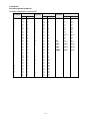
2.1 Technical Specification
Item
Parameter
Print Method
Direct Thermal
Resolution
203DPI (H) ×203DPI (V)
Print Width
80mm (Max.)
Print Speed
230mm/s (Max.)
Memory
RAM: 2MB
Drivers
Windows drivers (WIN98/NT/2000/XP/Vista)
Interface
Optional Parallel(IEEE1248), Serial (RS232C/RS485), USB, Ethernet, WLAN
Cash drawer
1~2 drives
Barcode Supported
UPC-A, UPC-E, EAN8, EAN13, CODABAR, CODE39, ITF, CODE128,CODE93, PDF417
Fonts
Font A: 12×24; Font B:9×17; GB2312; GB18030, Korean, Japanese, Traditional Chinese
Character Modification
Rotate (0°, 90°, 180°, 270°), enlarges(1-6X), emphasize, underline, white/black reverse
FLASH: 2MB/4MB
RAM bitmap download: buffer size is 12KB
Image process
FLASH bitmap download: buffer size is 256KB
Direct bitmap print: support bitmap and execute quick print
Paper near end
Optical sensor
Paper end
Optical sensor
Label
Optical sensor
Top cover position
Microswitch
Print head temperature
Thermistor
Paper type
Continuous paper, marked paper
Paper width
82.5 ± 0.5mm, 80 ± 0.5mm, 57.5 ± 0.5mm
Paper roll OD
Ø100 mm (Max.)
Paper cut
Tear off, Full cut, Partial cut
Input
100~240VAC, 50~60HZ
Output
24V±5% DC, 2.3A
Printer head lifetime
≥150Km(with reference paper)
Cutter lifetime
2,000,000 cuts (Paper type:F240AC/F220-VP)
Operation condition
5℃~45℃, 20%~90% RH (40℃)
Storage condition
-40℃~60℃, 20%~93%RH (40℃)
Dimensions
147 (W) × 205 (D) × 147 (H) mm
- 51 -
Confidential
RS-T80 Programming Manual
Thermal Printer
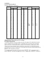
2.2 Cutter Specification
Item
parameter
Note
Cutter type
Slide cutter (Guillotine type)
Cutting time
600ms
The time that one cut takes
Cutting interval
2s
30 times/min. (Max.)
Paper type
0.06~0.1mm
Operation voltage
24VDC
Max. static curren
1.2A
Thermal paper or paper with the same
thickness
24VDC
2,000,000 cuts (reference paper
Cutter lifetime
with
thickness of 0.06 mm)
Full cut:
Partial cut: 2 mm paper left in middle
Full or partial cuts
Cut off the paper completely;
2.3 Paper Specification
2.3.1 Continuous paper
Paper type:
Continuous thermal paper
Paper supply method:
Paper roll
Paper width:
82.5±0.5mm,80±0.5mm, 57.5±0.5 mm
Paper thickness:
0.06mm-0.1mm
Thermal senstive layer: Outside
Paper roll specifications
OD(MAX):
ф100 mm
ID(Min):
ф15mm
Caution:
Do not paste the paper to the core.
If the paper is contaminated by a chemical or oil, it may discolor or lose heat
sensitivity at the polluted spot.
Do not rub the paper surface strongly against hard objects, otherwise it may
discolor.
When the temperature goes up to 70 degrees centigrade, paper will discolor.
Don’t use or store paper under high temperature, high humidity and strong light
conditions.
2.3.2 Marked paper
In marked paper mode, BTP-R580 determines the cut position and the initial printing
position by referencing the position of the black mark. Black marked paper should meet the
following requirement besides that of standard paper.
- 52 -
Confidential
RS-T80 Programming Manual
Thermal Printer
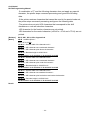
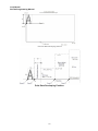
L1 Mark length: 3mm≤L1≤10mm.
L2 Mark length: L2≥12mm.
L3 Distance between marks: 20mm≤L3<500mm.
Mark position: Right, middle or left side on paper(80mm paper only)
Reflectivity: The reflectivity of the black mark must be less than 15% while the
reflectivity of the paper itself exceeds 85%. There shall be no printed objects like
text and images in the area between the black marks.
Caution:
The printer will measure the marks during the printing or feeding process. If the
lengths of the mark (L1) is larger than the default value (default: 13mm), the printer
will give a paper-end alarm.
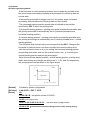
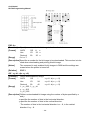
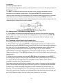
2.4 Print and cut position
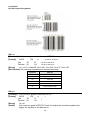
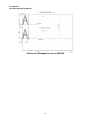
2.4.1 Print position
L1
Paper holder width: 83.5+0/-0.5mm
L2
Max Print width: 80mm
L3: Distance between left end of printhead and left side of paper
L4: Distance between right end of printhead and right side of paper holder(Fixed)
holder(Fixed) 1.8±0.3mm
1.8±0.3mm
L5: Left margin (default:7mm)
L6: Print area width. Can set by command (See Programming manual), default is
64mm.
L7: Right margin (default: 9mm)
- 53 -
Confidential
RS-T80 Programming Manual
Thermal Printer
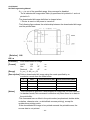
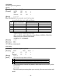
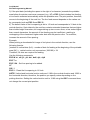
2.4.2 Cut position
L1: about: 30mm
- 54 -
L2: about: 11mm
Confidential
RS-T80 Programming Manual
Thermal Printer
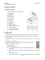
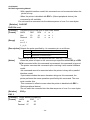
3 Outline and Parts
3.1 Outline and Parts
1—Paper near end sensor adjusting lever
2 —Paper holder
3 —Platen roller
4—Middle cover
5—Bottom cover
6 — Power switch
7—Paper guide
8—Top cover
9 — Cover spanner
10—Printhead
11—Paper roll shaft
12—Printhead support plate
13 —Power connector
14 —Communicate interface
15 —Cash drawer connector
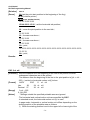
Functions of parts:
a) Paper guide
Removing the paper guide or putting it in a different slot will allow the printer to use
different paper widths listed as follows: 82.5±0.5 mm, 80.5±0.5 mm, 57.5±0.5 mm.
b) Power switch
Switching the power of the printer on or off. “O” power is turned off. “—” power is turned
on.
c) Feed button (See Fig 3.1-3)
Switching on the printer while pressing the FEED button will start the
printing of the configuration table。
In normal status:
Continuous paper mode:
The printer will feed one line when pressing the FEED button for
a short time.
The printer will feed continuously when pressing the FEED button for a longer
time
Marked paper mode:
The printer will feed one line when pressing the FEED button for a short time.
- 55 -
Confidential
RS-T80 Programming Manual
Thermal Printer
The printer will locate the marks when pressing the FEED button for a longer
time.
In error status, the printer will have no activity when the FEED button is pressed.
d) Power Indicator
Indicating power status (ON/OFF).
e) Error indicator
Indicating some error status. Under normal conditions, ERROR LED is always off.
Under some error conditions(Cover Open、Cutter Error、Print head is overheating、
Input voltage is abnormal), ERROR LED will flash.
f) Paper indicator
Indicating paper status. Under normal conditions, PAPER LED is always off. When the
paper status changes (paper end or paper near end), PAPER LED will flash.
g) Paper end sensor
The paper-end sensor is used to detect whether the paper roll is out of paper.
Notices:
The paper guide is an indispensable part of the printer and should be kept with the
printer.
3.2 Error LED and Buzzers
1) Error LED
Led
Status
Description
On
Printer is powered on
Off
Printer is powered off
Off
Printer is in normal status
Flash
Printer is in error status
On
Paper end or near end
Power Indicator (Green) (POWER)
Error Indicator (Red) (ERROR)
Paper Indicator (Red) (PAPER)
Flash
Off
Macro definition is running
Printer is in normal status
2) Description of LED and Error Status
Error information
ERROR LED
PAPER LED
Buzzer
Print head is overheating
Six times
Off
Long-Short-Long
Input voltage is abnormal
Five times
Off
Short-Short-Long
Cutter Error
Four times
Off
Long-Short-Long
Cover Is Open
Three times
Off
Short-Long-Short
Paper End
Twice
On
Short-Short-Short
Paper near end
Off
On
Finding mark error or verify failed
Flashing continuously
Off
Caution:
The temperature of the print-head is detected by means of a thermistor sensor. If the
- 56 -
Confidential
RS-T80 Programming Manual
Thermal Printer
temperature of the printhead becomes higher than 650 C, the protection circuit of the
printer will force the printer to stop printing.
4 Installation
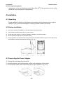
4.1 Unpacking
Check whether all items, that are listed on the packing list are present and in a good
condition. If any items are damaged or missing, please contact your dealer.
4.2 Printer installation
1)
The printer should be installed on a flat and stable horizontal surface.
2)
The printers should be away from any water source.
3)
Do not place the printer on a surface exposed to vibration or risk from impact.
4)
Ensure that the printers can be grounded safely.
5)
During operation and maintenance of the printer there should be sufficient space around the printer
in accordance with the dimensions as shown in fig. 4.2-1.
4.3 Connecting the Power Adapter
1) Ensure the printer power is turned off.
2)Insert the power cord into the power socket on the backside of the printer.
3)Fix the power cable cord in the printer with a clip as shown in Fig. 4.3-1.
- 57 -
Confidential
RS-T80 Programming Manual
Thermal Printer
Caution:
When connecting or disconnecting the power cord, always hold the plug and avoid
dragging it by force.
Do not pull on the power cord, otherwise the cord may be damaged or broken, causing
a risk of fire or electric shock.
Do not place the power cord near a heating device, otherwise, the cover of the cord
may melt, causing a risk of fire or electric shock.
If the printer is not in use for a long period, disconnect the power cord from the wall
outlet for safety.
4.4 Connecting interface cable
1) Ensure the printer power is turned off.
2) Connect the suitable interface cable with the correct connector to the connector of the
interface board of the printer plug screws (Serial interface) or clip springs (Parallel
interface).
3) Connect the other end of the interface cable to the host.
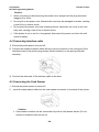
4.5 Connecting the Cash Drawer
1)Ensure the printer power is turned off.
2) Insert the cash drawer cable into the cash drawer connector on the back of the printer.
Caution:
Cash drawer interface can be connected only with a cash drawer device (Do not
connect a telephone line and so on).
- 58 -
8
Confidential
RS-T80 Programming Manual
Thermal Printer
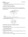
4.6 Paper roll loading
4.6.1 Confirm the paper type
After connecting of the printer to the mains voltage, with the host and, if applicable, to
the cash drawer, the paper can be loaded and printed.
4.6.2 Load/replace a paper roll
1) Press the latch of the top cover and open it.
2) Place a paper roll in the paper holder.
3) Close the printer top cover.
Caution:
If needed remove the paper guide. Choose the suitable paper guide position according
to the width of the paper roll and mount the paper guide. When inserting the paper roll
pay attention to the paper path direction.
Note: Without paper guide:
Paper guide in the slot A:
Paper guide in the slot B:
82.5±0.5mm.
80±0.5mm
57.5±0.5mm
Ensure that the paper is rolled tightly onto the paper roll, otherwise a paper jam or other
- 59 -
Confidential
RS-T80 Programming Manual
Thermal Printer
fault could happen.
The paper roll should be placed straight in the paper holder and not at an angle. The
paper roll should be able to move freely.
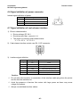
4.7 Paper near end position adjustment
Through adjustment of the latch of the paper near end sensor to a corresponding level,
different paper roll cores can be accommodated and also the remaining paper-end length
can be approximated.
Caution:
The factory setting of the paper near end sensor is level 1.
1) When using different Diameter core shaft, C diameter may be different with the length of
the remaining paper at the same level.
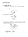
4.8 Switching on the printer and printing of self-test
4.8.1 Switching on the printer
1) Ensure that the printer is connected to the mains voltage and, if applicable, that the
mains voltage is switched on.
2) Switch on the power of the printer.
4.8.2 Printing a self-test page
1) Confirm that the printer is connected to the mains voltage and that a paper roll is in the
printer.
2) Confirm that the printer is switched off.
3) Press down the FEED button while switching on the printer, the printer will start printing
- 60 -
Confidential
RS-T80 Programming Manual
Thermal Printer
the configuration sheet. At the end of the configuration sheet the followings text will
appear: “Press feed key to continue” The printer is holding and waiting for the input
while the PAPER LED is flashing.
4) Press down the FEED button shortly, the printer will print a character test page which is
part of the self-test.
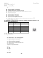
4.9 Setting of printer parameters and configuration
The parameters of the printer can be set (configuring) in a detailed way by means of
the utility software that is available from the reseller or from SNBC by special request.
- 61 -
Confidential
RS-T80 Programming Manual
Thermal Printer
5 Printer routine maintenance
Caution:
Before starting routine maintenance, ensure that the printer is switched off.
Do not use solvents like gasoline or acetone.
When cleaning sensors, the printer should not be switched on until the pure alcohol has
totally evaporated.
It is recommended that the maintenance cycle should not be longer than one month.
5.1 Cleaning the platen
The steps for cleaning the platen are as given below:
1) Switch off the printer.
2) Open the top cover of the printer.
3) When the top cover is opened, wipe off stain such as dust on the platen by using a soft
cotton cloth with neutral cleaning agent.
4) Close the top cover after the alcohol has evaporated completely.
5.2 Cleaning the mark sensors
The black mark sensors need to be cleaned if the printer has trouble identifying the black
marks.
The steps for cleaning sensors are as below:
1) Switch off the printer.
2) Open the top cover of the printer.
3) Wipe off stain or dust from the surface of sensors by using a soft cotton swipe
impregnated with pure alcohol.
4) Close the top cover of the printer after the alcohol has evaporated completely.
5.3 Clearing of a paper jam
Remove the paper, if one of the following phenomena occurs:
The printer fails to feed out paper normally.
Paper is feeding with load noise.
The steps for removing paper are as below:
1) Switch off the printer.
2) Open the top cover of the printer.
3) If the paper is jammed in the paper path, remove the wrinkled or wasted part of the
paper roll.
4) Close the printer top cover.
- 62 -
Confidential
RS-T80 Programming Manual
Thermal Printer
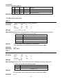
6 Interface signal
6.1 Parallel interface
Parallel interface can work in IEEE 1284 compatible mode or half-byte mode, which is
a 36 pin socket.
The Interface is defined as below:
Pin#
Signal source
Signal definition
1
H
NStrobe
2
H
Data 0 (Least Significant Bit)
3
H
Data 1
4
H
Data 2
5
H
Data 3
6
H
Data 4
7
H
Data 5
8
H
Data 6
9
H
Data 7 (Most Significant Bit)
10
P
NAck
11
P
Busy
12
P
Perror
13
P
Select
14
H
nAutoFd
15
Not defined
16
Logic Gnd
17
Chassis Gnd
18
P
Peripheral Logic High
19
Signal Ground (nStrobe)
20
Signal Ground (Data 1)
21
Signal Ground (Data 2)
22
Signal Ground (Data 3)
23
Signal Ground (Data 4)
24
Signal Ground (Data 5)
25
Signal Ground (Data 6)
26
Signal Ground (Data 7)
27
Signal Ground (Data 8)
28
Signal Ground (PError, Select, and nAck)
29
Signal Ground
30
(Busy and nFault)
Signal Ground (nAutoFd, nSelctIn, and nInit)
31
H
NInit
32
P
NFault
33
Not defined
34
Not defined
35
36
Not defined
H
nSelectIn
- 63 -
Confidential
RS-T80 Programming Manual
Thermal Printer
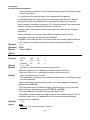
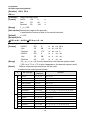
6.2 Serial interface
The serial interface of the printer is compatible with RS-232 and is equipped with a 25-pin
female D type connector.
PIN No.
Signal definition
PIN1
Frame Ground
PIN2
TXD
PIN 3
RXD
PIN 4
DTR
PIN 5
Not connected
PIN6
DSR
PIN 7
Signal Ground
PIN 8~19
Not connected
PIN 20
DTR
PIN 21~25
Not connected
The user may check the current setting status of the interface by printing a configuration
table. The default setting is as follows:
Baud rate: 19200bps, 8 data bit, none Parity, 1 stop bit
Handshake: DTR/DSR
6.3 USB interface
Parameters
Data transmission: Support USB1.1 protocol
Connector (Printer side): USB B type socket. Support and pass USB HUB
Interface signal definition and functions
Pin No.
Signal
Description
1
VBUS
+5V
2
DATA-
Printer data transmit line minus
3
DATA+
Printer data transmit line plus
4
GND
Ground
Interface connector
- 64 -
Confidential
RS-T80 Programming Manual
Thermal Printer
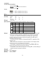
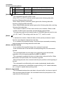
6.4 Ethernet interface
Feature
Supports 10BASE-T communication
Compatible with Ethernet II standard frame type
LEDs indicate network connecting status and data transmission status.
Supports 9100 port print
Supports ASB(Auto status back)
Supports parameter configuration
Supports firmware program updated online
Supports printer status query and interface module maintenance based on HTTP.
Interface signal definition
The parameters of Ethernet interface socket match 10BASE-T standard of IEEE802.3. The
interface signal is defined as below:
Pin
Signal name
Description
1
TX+
Data sending+
2
TX-
Data sending-
3
RX+
Data reception+
4
NC
Reserve
5
NC
Reserve
6
RX-
Data reception-
7
NC
Reserve
8
NC
Reserve
6.5 WLAN interface
Features
Supports 802.11b、802.11g communication
Supports 9100 port print and LPR print
Supports ASB (Auto Status Back)
Supports parameter configuration
Supports firmware program upgraded online
Supports HTTP
Protocols are supported as below
IP
ARP
ICMP
TCP
UDP
DHCP
- 65 -
Confidential
RS-T80 Programming Manual
TFTP
HTTP
Thermal Printer
WLAN interface uses wireless USB network card of which the main specification should be
requested from the local distributor or manufacture.
- 66 -
Confidential
RS-T80 Programming Manual
Thermal Printer
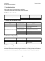
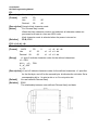
6.6 Signal definition of power connector
Internal signal definition of power
Pin
Signal name
1
E
2
L
3
N
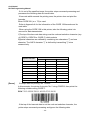
6.7 Signal definition of cash drawer interface
1) Electric characteristics
Driving voltage: DC 24 V
Driving current: Max. current is 1 A
The signal for checking cash drawer status:
“L” = 0~0.5 V “H” = 3.3 V
2) Cash drawer interface socket uses RJ-11 6P connector.
3) Interface signal definition
No.
Signal
Functions
1
FG
Frame
2
DRAWER 1
Driving signal of cash drawer1
3
DRSW
Check signal for cash drawer status
4
VDR
Cash drawer driving power
5
-
NC
6
GND
Common port with circuit
Caution:
Do not allow disconnection or connection of the interface cable plug when the printer
and the host are switched on.
Avoid the presence of devices like motors with large power as these may cause
voltage fluctuations.
Always use shielded interface cables.
- 67 -
Confidential
RS-T80 Programming Manual
Thermal Printer
7 Troubleshooting
Refer to this section if the printer has any problems.
If the problem cannot be solved, please contact your dealer.
7.1 Printer doesn’t work
Faults
Possible reasons
Power LED is off and the printer doesn’t work
Solution
Printer is off
Connect the printer power
Printer is off
Turn on the printer
Circuit board is damaged
Contact your dealer
7.2 Alarm LED and buzzer sound
Faults
Paper LED on
and buzzer sounds
Paper LED on
Possible reasons
Paper end
Replace with new paper roll
Paper near end
Replace with new paper roll
Input voltage is abnormal
Alarm LED flashes and buzzer sounds
Solution
Print head is overheated
Turn off the printer power and check
The input voltage
Turn off the printer power and wait for the print
head temperature recovered normally
Cutter Error
Cutter resetting(reference 7.4)
Cover is Open
Close the cover again
Serious fault occurs
Contact your dealer
7.3 Problems with printing
Faults
Possible reasons
Solution
Printout is light
Print head is damaged
Replace print head
Printout is not clear or has dirt
Print head or platen is dirty
Clean print head or platen
Paper cannot be fed out properly
Paper jam
Open top cover and check paper path to
remove paper jam
7.4 Cutter resetting
If the moving blade of the cutter does not return to its home-position, then the top cover
should be opened and the printer should be switched on. This will force the moving blade to
reset and return to its home-position. Please contact your dealer if the problem persists.
- 68 -
CHAPTER7
Appendix (B) – Thermal Printer
RS-T80
Programming Manual
Shandong New Beiyang Information Technology Co., Ltd.
69
Confidential
RS-T80 Programming Manual
Thermal Printer
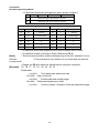
REVISION HISTORY
Date
Version
July 30, 2007
1.00
Jan 14, 2008
1.01
Description
Primary version
Change the format of command list
Add Water Mark Commands
- 70 -
Drafted by
Ms Weiwei Xu
Mr. Peng Geng
Ms Weiwei Xu
Confidential
RS-T80 Programming Manual
Thermal Printer
Declaration
If you need this manual, please comply with the Clause as below.
If you disagree with it, please return this manual immediately.
This manual contains the private confidential information belonging to Shandong New
Beiyang Info-Tech Co., Ltd. (hereinafter referred to as SNBC) or its distributors. You must
keep its relative content as the confidential information. If the users are commercial
customers or entities, you should be aware to disclose it to those people with the
confidential responsibility including your employees, agencies and partners. When you
terminate the cooperation with SNBC or bring about your request, you have to stop using
this manual and return it to SNBC or its distributor, or destroy the confidential information.
If any relative organ such as court, arbitrator or government authority requests you to
disclose any confidential information of this manual, you must inform SNBC quickly and
also agree that you shall cooperate or assist with SNBC reasonably during the negotiation.
SNBC has the right to disclose its confidential information and does not be responsible for
the loss or damages caused from the wrong usage or reference of this manual by users.
Information in this document is subject to change without notice, which is only used for
product maintenance or service relative to this manual. SNBC reserves the right to improve
products as new technology, components, software, and firmware become available. If
users need further data about the products, please feel free to contact SNBC or your local
distributor.
No part of this document may be reproduced or transmitted in any form or by any means,
electronic or mechanical, for any purpose without the express written permission of SNBC.
Copyright
Copyright© 2007 by SNBC
Printed in China
Version 1.01
Trademarks
Our registered trademarks are
- 71 -
Confidential
RS-T80 Programming Manual
Thermal Printer
Contents
1 Overview
74
1.1 Commands classification
74
1.2 Key terms
74
1.3 Command format
75
2 Command Description
76
2.1 Print command
76
LF .............................................................................................................................................. 76
FF .............................................................................................................................................. 76
CR ............................................................................................................................................. 76
ESC FF ...................................................................................................................................... 76
ESC J n ..................................................................................................................................... 77
ESC d n ..................................................................................................................................... 77
2.2 Location command
78
HT .............................................................................................................................................. 78
ESC $ nL nH.............................................................................................................................. 79
ESC D n1...nk NUL .................................................................................................................... 80
ESC T n ..................................................................................................................................... 80
ESC W xL xH yL yH dxL dxH dyL dyH ...................................................................................... 82
ESC \ nL nH............................................................................................................................... 84
ESC a n ..................................................................................................................................... 85
GS $ nL nH ................................................................................................................................ 86
GS L nL nH ................................................................................................................................ 86
GS P x y .................................................................................................................................... 87
GS W nL nH .............................................................................................................................. 88
GS \ nL nH ................................................................................................................................. 89
2.3 Character command
89
CAN ........................................................................................................................................... 89
ESC SP n .................................................................................................................................. 90
ESC ! n ...................................................................................................................................... 91
ESC % n .................................................................................................................................... 94
ESC & y c1 c2 [x1 d1...d(y × x1)]...[xk d1...d(y × xk)] ................................................................ 94
ESC – n ..................................................................................................................................... 96
ESC ? n ..................................................................................................................................... 97
ESC E n ..................................................................................................................................... 97
ESC G n .................................................................................................................................... 98
ESC M n .................................................................................................................................... 98
ESC R n..................................................................................................................................... 99
ESC V n ..................................................................................................................................... 99
ESC t n .................................................................................................................................... 100
ESC { n .................................................................................................................................... 100
GS ! n ...................................................................................................................................... 101
GS B n ..................................................................................................................................... 102
FS ! n ....................................................................................................................................... 103
FS & ........................................................................................................................................ 104
FS - n ....................................................................................................................................... 104
FS . .......................................................................................................................................... 105
FS 2 c1 c2 d1...dk .................................................................................................................... 105
- 72 -
Confidential
RS-T80 Programming Manual
Thermal Printer
FS S n1 n2............................................................................................................................... 106
FS W n..................................................................................................................................... 107
2.4 Bitmap Command
107
ESC * m nL nH d1... dk............................................................................................................ 107
ESC # n ................................................................................................................................... 109
GS * x y d1...d(x × y × 8) ......................................................................................................... 109
GS / m ..................................................................................................................................... 110
GS v 0 m xL xH yL yH d1....dk................................................................................................. 111
FS p n m .................................................................................................................................. 112
FS q n [xL xH yL yH d1...dk]1...[xL xH yL yH d1...dk]n ............................................................ 112
DLE EOT n .............................................................................................................................. 115
GS a n ..................................................................................................................................... 116
GS r n ...................................................................................................................................... 118
2.6 Barcode command
119
GS H n ..................................................................................................................................... 119
GS f n ...................................................................................................................................... 119
GS h n ..................................................................................................................................... 120
①GS k m d1...dk NUL②GS k m n d1...dn ............................................................................... 120
GS p n ..................................................................................................................................... 124
GS q n ..................................................................................................................................... 124
GS w n ..................................................................................................................................... 125
2.7 Other commands
125
DLE ENQ n .............................................................................................................................. 125
DLE DC4 n m t ........................................................................................................................ 126
ESC 2 ...................................................................................................................................... 126
ESC 3 n ................................................................................................................................... 127
ESC = n ................................................................................................................................... 127
ESC @ .................................................................................................................................... 129
ESC L ...................................................................................................................................... 129
ESC S ...................................................................................................................................... 129
ESC c 0 n ................................................................................................................................ 131
ESC c 3 n ................................................................................................................................ 131
ESC c 4 n ................................................................................................................................ 133
ESC c 5 n ................................................................................................................................ 134
ESC p m t1 t2 .......................................................................................................................... 134
GS FF ...................................................................................................................................... 134
GS ( A pL pH n m .................................................................................................................... 135
GS : ......................................................................................................................................... 135
①GS V m ②GS V m n ............................................................................................................ 136
GS ^ r t m ................................................................................................................................ 136
GS { w...................................................................................................................................... 137
GS { w f.................................................................................................................................... 137
3 Programming Process Guide
140
Appendix
141
Appendix A: Code128 Bar Code
141
Appendix B: Print mode and its change
144
Appendix C: Control Sequences
149
- 73 -
Confidential
RS-T80 Programming Manual
Thermal Printer
1 Overview
This manual classifies the printer commands into several kinds based on its functions, and
also describes the applications of relative commands in detail depending on its sorts. We
hope that it is helpful for programmers to get known of those commands.
1.1 Commands classification
This receipt printer commands are classified as below:
Print commands: used for printing and feeding paper;
Position commands: to control the print position;
Character commands: to set characters property;
Bitmap commands: to download bitmap and print, including NV and RAM bitmap;
Status commands: used for printer status query;
Barcode commands: barcode print and property settings;
Other commands: used for periphery control, Micro-definition and initialization;
Command instruction refers to the detailed function of relative commands.
1.2 Key terms
Real-time commands – These commands are acted on immediately upon being received
by the printer.
Print buffers – used to store figure data to be printed;
Page mode –Under this mode, the printer possesses all data in specified memory and
thinks of this as a virtual page. The page is printed when the printer receives print
command either FF or ESC FF;
Standard mode – Standard mode is the default mode of printer, namely line mode. Under
this mode, the printer prints data and feeds paper upon print line buffer full (data is enough
for one print line) or receiving print command like LF;
HRI character – Human Readable Interface;
NV – Non-volatile memory in which data stored does not loss when power off.
RAM –Random Access Memory;
DPI – Print dots per inch (one inch equals to 25.4mm). It is used to identify the resolution of
a printer. Example, 203DPI means 203 print dots per inch.
Baseline – The standard position where character data in print buffers are stored. The
figure shows the position of ordinary characters in standard mode and page mode:
- 74 -
Confidential
RS-T80 Programming Manual
1.3 Command format
[Function]
[Format]
[Range]
[Note]
[Default]
[Relative]
[Demo]
The name and function summary of commands;
The command expressed in ASCII, Hex and Decimal separately. If not
specified, the value in “range” part is decimal. For instance, in range” 1 ≤ n≤
4”, ‘1’ is not an ASCII code but a decimal number;
The value range of parameter in the command;
Explain the main features and application notices of commands;
The initial value used after the printer initialized;
Other commands related to current commend;
Example used for current or relative commands.
All command data in programming Demo use HEX. All normal
font/characters are data. There is no explanation for the data of command
such as 42 43 which is data. The font/character underlined and emphasized
is a command such as 1B 40. All the data inside parentheses after all
commands in Demo is used to explain the meanings of this command. The
parentheses and data inside it is not the command to be transmitted to the
printer.
- 75 -
Confidential
RS-T80 Programming Manual
2 Command Description
2.1 Print command
LF
Print and line feed
ASCII
LF
Hex
0A
Decimal
10
[Note]
This command sets the print position to the beginning of the line.
[Reference] ESC 2, ESC 3
[Function]
[Format]
FF
Print all data in the print buffers and return to the standard mode.
ASCII
FF
Hex
0C
Decimal
12
[Notes]
· This command is valid only in page mode.
· The buffer data is deleted after being printed.
· The printer does not execute paper cutting.
· This command sets the print position to the beginning of the line.
[Relative] ESC FF, ESC L, ESC S
[Function]
[Format]
CR
When the command is enabled, it equals to LF; it is ignored when disabled,
ASCII
CR
Hex
0D
Decimal
13
[Notes]
· Sets the print starting position to the beginning of the line.
· This command is set according to the printer configuration.
[Relative] LF
[Function]
[Format]
ESC FF
[Function]
[Format]
[Notes]
Print data in page mode
ASCII
ESC
FF
Hex
1B
0C
Decimal 27
12
· This command is enabled only in page mode.
· After printing, the printer does not clear the buffered data, setting values for
ESC T and ESC W, and the position for buffering character data.
- 76 -
Confidential
RS-T80 Programming Manual
[Relative]
FF, ESC L, ESC S
ESC J n
Print and feed paper
ASCII
ESC
J
n
Hex
1B
4A
n
Decimal
27
74
n
[Range]
0 ≤n ≤ 255
[Notes]
· After printing is completed, this command sets the print starting position to
the beginning of the line.
· The paper feed amount set by this command does not affect the values set by
ESC 2 or ESC 3.
· The horizontal and vertical motion unit are specified by GS P.
· In standard mode, the printer uses the vertical motion unit (y).
· In page mode, this command functions as follows, depending on the starting
position of the printable area:
1) When the starting position is set to the upper left or lower right of the
printable area using ESC T, the vertical motion unit (y) is used.
2) When the starting position is set to the upper right or lower left of the print
able area using ESC T, the horizontal motion unit (x) is used.
· The maximum line spacing is 1016mm (40 inches). When the setting value
exceeds the maximum, it is converted to the maximum automatically.
[Relative] GS P
[Example] 1B 40 (initialize printer)
1D 50 CB CB (set the resolution 203×203)
[Function]
[Format]
41 41 41 41 41 41 41( datas waiting for printing)
1B 4A 50 (print and feed paper 80/203 inches)
42 42 42 42 42 42 42 0A ( datas waiting for printing)
Results:
ESC d n
[Function]
[Format]
[Range]
Print and feed n lines
ASCII
ESC
d
Hex
1B
64
Decimal
27
100
0 ≤n ≤ 255
n
n
n
- 77 -
Confidential
RS-T80 Programming Manual
[Notes]
· This command sets the print starting position to the beginning of the line.
· This command does not affect the line spacing set by ESC 2 or ESC 3.
· The maximum paper feed amount is 1016 mm (40 inches). If the paper feed
amount (n x line spacing) of more than 1016 mm (40 inches) is specified, the
printer feeds the paper only 1016 mm (40 inches).
[Relative]
ESC 2, ESC 3
[Demo]
1B 40(initialize printer)
41 41 41 41 41 41 41(datas waiting for printing)
1B 64 02(print and feed 2 characters line spacing, 2/6 inches)
42 42 42 42 42 42 42 0A(datas waiting for printing)
Results:
2.2 Location command
HT
[Function]
[Format]
[Notes]
Moves the print position to the next horizontal tab position.
ASCII
HT
Hex
09
Decimal
9
• This command is ignored unless the next horizontal tab position has been
set.
• If the next horizontal tab position exceeds the printing area, the printer sets
the printing position to [Printing area width + 1].
• Horizontal tab positions are set with ESC D.
• If this command is received when the printing position is at [printing area
width + 1], the printer executes print buffer-full printing of the current line and
horizontal tab processing from the beginning of the next line.
• The default setting of the horizontal tab position for the paper roll is font A
(12×24) every 8th character.
• When current buffer is full, the printer shall execute the actions as below:
In standard mode, the printer shall print current line and set the print position
to the beginning of next line;
• In page mode, the printer shall shift the line and set the print position to the
beginning of next line.
- 78 -
Confidential
RS-T80 Programming Manual
[Relative]
[Demo]
ESC D
0A (set the print start position to the beginning of the ling)
1B 40 (initialize printer)
1B 53(enter standard mode)
33 33 33 33 33 33
1B 44 08 10 1C 00(set the horizontal tab position)
09(move the print position to the next tab)
33 33 33 33
09(the same as above)
33 33 33 33
09(the same as above)
33 33 33 33
0A(print)
33 33 33 33 33 33 33 33 33 33 33 33 33 33 33 33 33 33 33 33 33 33 33 33 33
33 33 33
0A(print)
Results:
ESC $ nL nH
[Function] Sets the distance from the beginning of the line to the position at which
subsequent characters are to be printed.
· The distance from the beginning of the line to the print position is [(nL + nH ×
256) × (vertical or horizontal motion unit)] inches.
[Format]
ASCII
ESC
$ nL nH
Hex
1B
24 nL nH
Decimal 27
36 nL nH
[Range]
0≤nL ≤ 255
0 ≤nH≤255
[Notes]
· Settings outside the specified printable area are ignored.
· The horizontal and vertical motion units are specified by GS P.
· In standard mode, the horizontal motion unit (x) is used.
· In page mode, horizontal or vertical motion unit differs depending on the
starting position of the printable area as follows:
1) When the starting position is set to the upper left or lower right of the
- 79 -
Confidential
RS-T80 Programming Manual
[Relative]
[Demo]
printable area using ESC T, the horizontal motion unit (x) is used.
2) When the starting position is set to the upper right or lower left of the
printable area using ESC T, the vertical motion unit (y) is used.
ESC \, GS $, GS \, GS P
Refer to ESC W
ESC D n1...nk NUL
[Function]
[Format]
[Range]
[Notes]
Set horizontal tab positions
ASCII
ESC
D n1... nk NUL
Hex
1B
44 n1...nk 00
Decimal
27
68 n1...nk 0
1 ≤ n ≤ 255
1 ≤ k ≤ 32
· The horizontal tab position is stored as a value of [character width × n]
measured from the beginning of the line. The character width includes the
right-side character spacing, and double-width characters are set with twice
the width of normal characters.
· This command cancels the previous horizontal tab settings.
·When setting n = 8, the print position is moved to column 9 by sending HT.
·Up to 32 tab positions (k = 32) can be set. Data exceeding 32 tab positions is
processed as normal data.
·Transmit [n] k in ascending order and place a NUL code 0 at the end.
·When [n] k is less than or equal to the preceding value [n] k-1, tab setting is
finished and the following data is processed as normal data.
· ESC D NUL cancels all horizontal tab positions.
·The previously specified horizontal tab positions do not change, even if the
character width changes.
·The character width is memorized for each standard and page mode.
[Default]
The default tab positions are at intervals of 8 characters (columns 9, 17, 25...)
for font A (12 × 24).
[Relative]
[Demo]
HT
Refer to HT
ESC T n
[Function]
[Format]
[Range]
Selects the print direction and starting position in page mode.
ASCII
ESC
T
n
Hex
1B
54
n
Decimal
27
84
n
0≤n≤3
48 ≤ n ≤ 51
- 80 -
Confidential
RS-T80 Programming Manual
· When the command is input in standard mode, the printer executes only
internal flag operation. This command does not affect printing in standard
mode.
· This command sets the position where data is buffered within the printing
area.
· Parameters for horizontal or vertical motion units (x or y) differ as follows,
depending on the starting position of the printing area:
1) If the starting position is the upper left or lower right of the printing area,
data is buffered in the direction perpendicular to the paper feed direction:
Commands using horizontal motion units: ESC SP, ESC $, ESC \
Commands using vertical motion units: ESC 3, ESC J, GS $, GS \
2) If the starting position is the upper right or lower left of the printing area,
data is buffered in the paper feed direction:
Commands using horizontal motion units: ESC 3, ESC J, GS $, GS \
Commands using vertical motion units: ESC SP, ESC $, ESC \
[Default]
n=0
[Relative] ESC $, ESC L, ESC W, ESC \, GS $, GS P, GS \
[Notes]
[Demo]
1B 4C (enter page mode)
1D 50 CB CB(set printer resolution)
1B 57 20 00 00 00 40 02 90 02 (set the print area in page mode)
1B 54 00(select the print area direction in page mode)
30 30 30 30 30 30 30 30 30 30 30 30 30 30 30 30 30 30 30 30 30 30 30 30 30
0A (newline)
1B 54 01(select the print area direction in page mode)
31 31 31 31 31 31 31 31 31 31 31 31 31 31 31 31 31 31 31 31 31 31 31 31 31
0A(newline)
1B 54 02(select the print area direction in page mode)
- 81 -
Confidential
RS-T80 Programming Manual
32 32 32 32 32 32 32 32 32 32 32 32 32 32 32 32 32 32 32 32 32 32 32 32 32
0A (newline)
1B 54 03 (select the print area direction in page mode)
33 33 33 33 33 33 33 33 33 33 33 33 33 33 33 33 33 33 33 33 33 33 33 33 33
0A(print)
50 72 69 6E 74 20 45 6E 64
0C(print)
Results:
ESC W xL xH yL yH dxL dxH dyL dyH
[Function] · Define the horizontal starting position, vertical starting position, printing area
width, and printing area height.
[Format]
ASCII
ESC
W xL xH yL yH dxL dxH dyL dyH
Hex
1B
57 xL xH yL yH dxL dxH dyL dyH
Decimal
27
87 xL xH yL yH dxL dxH dyL dyH
[Range]
0 ≤ xL, xH, yL, yH, dxL, dxH, dyL, dyH ≤ 255 (except dxL= dxH=0 or dyL=
dyH=0)
[Notes]
· If this command is input in standard mode, the printer executes only internal
flag Each the horizontal starting position, vertical starting position, printing
area width, and printing area height are defined as x0、y0、dx、dy setting for
the printing area is calculated as follows:
x0 = [( xL + xH × 256) × (horizontal motion unit)]
y0 = [( yL + yH × 256) × (vertical motion unit)]
dx = [ dxL + dxH × 256) × (horizontal motion unit)]
dy = [ dyL + dyH × 256) × (vertical motion unit)]
The printing area is set as shown in the figure below.
This command does not affect printing in standard mode.
- 82 -
Confidential
RS-T80 Programming Manual
· If the horizontal or vertical starting position is set outside the printable area,
the printer stops command processing and processes the following data as
normal data.
· If the printing area width or height is set to 0, the printer stops command
processing and processes the following data as normal data.
· This command sets the position where data is buffered to the position
specified by ESC T within the printing area.
· If (horizontal starting position + printing area width) exceeds the printable area,
the printing area width is automatically set to (horizontal printable area
horizontal starting position).
· If (vertical starting position + printing area height) exceeds the printable area,
the printing area height is automatically set to (vertical printable area – vertical
starting position).
· The horizontal and vertical motion unit are specified by GS P. Changing the
horizontal or vertical motion unit does not affect the current printing area.
· Use the horizontal motion unit (x) for setting the horizontal starting position
and printing area width, and use the vertical motion unit ( y) for setting the
vertical starting position and printing area height.
· When the horizontal starting position, vertical starting position, printing area
width, and printing area height are defined as X, Y, Dx, and Dy respectively,
the printing area is set as shown in the figure below.
[Default]
[Relative]
[Demo]
Decided by printer configuration
CAN, ESC L, ESC T, GS P
0A
1D 50 CB CB(set printer solution 203×203)
1B 4C (enter page mode)
1B 57 20 00 00 00 40 01 90 01 (set print area in page mode)
1B 24 00 00(set absolute honzontal starting position to be starting point)
41
- 83 -
Confidential
RS-T80 Programming Manual
1B 24 32 00(set absolute honzontal starting position to be 50/203 inches)
42
1B 24 64 00(set absolute honzontal starting position to be 100/203 inches)
43
0A(newline)
1B 24 00 00(set absolute honzontal starting position to be starting point)
41
1B 5C 32 00(set absolute honzontal starting position to be 50/203 inches)
1B 5C 64 00(set relative honzontal starting position to be 100/203 inches)
43
0A(newline)
0C(print in page mode)
Results:
ESC \ nL nH
[Function]
[Format]
[Range]
[Notes]
Sets the print starting position based on the current position by using the
horizontal or vertical motion unit.
· This command sets the distance from the current position to [(nL + nH × 256)
× horizontal or vertical motion unit]
ASCII
ESC
\
nL
nH
Hex
1B
5C nL
nH
Decimal
27
92 nL
nH
0 ≤ nL ≤ 255
0 ≤ nH ≤ 255
· Any setting that exceeds the printable area is ignored.
· When pitch N is specified to the right: nL+ nH × 256 = N
When pitch N is specified to the left (the negative direction), use the
complement of 65536.
When pitch N is specified to the left: nL+ nH × 256 = 65536 - N
- 84 -
Confidential
RS-T80 Programming Manual
· The print starting position moves from the current position to [N × horizontal or
vertical motion unit]
· The horizontal and vertical motion units are specified by GS P.
· In standard mode, the horizontal motion unit is used.
· In page mode, the horizontal or vertical motion unit differs as follows,
depending on the starting point of the printing area:
1) When the starting position is set to the upper left or lower right of the
printable area using ESC T, the horizontal motion unit (x) is used.
2) When the starting position is set to the upper right or lower left of the
printable area using ESC T, the vertical motion unit (y) is used.
[Relative] ESC $, GS P
ESC a n
[Function]
[Format]
Aligns all the data in one line to the specified position
ASCII
ESC
Hex
Decimal
[Range]
a
n
1B 61
n
27 97
n
0 ≤ n ≤ 2, 48 ≤ n ≤ 50
n selects the justification as follows:
[Notes]
n
Justification
0,48
Left justification
1, 49
Centering
2, 50
Right justification
• This command is enable only when processed at the beginning of the line in the
standard mode.
• If this command is input in page mode, the printer performs only internal flag
operations.
• This command justifies the space area according to HT, ESC $ or ESC\.
[Default]
n=0
[Demo]
0A(Entering line mode)
1B 40(Initialization)
1B 61 00(Setting left justification)
41 42 43 0A
41 42 43 44 0A
41 42 43 44 45 0A
1B 61 01(Setting centering )
41 42 43 0A
41 42 43 44 0A
41 42 43 44 45 0A
- 85 -
Confidential
RS-T80 Programming Manual
1B 61 02(Setting right justification)
41 42 43 0A
41 42 43 44 0A
41 42 43 44 45 0A
Results:
GS $ nL nH
[Function]
This command sets the absolute print position to [( nL + nH × 256) × (vertical or
horizontal motion unit)] inches.
[Format]
ASCII
GS
$
nL nH
Hex
1D
24
nL nH
Decimal
29
36
nL nH
[Range]
0 ≤ nL ≤ 255, 0 ≤ nH ≤ 255
[Notes]
• This command is effective only in page mode.
• If the [( nL + nH × 256) × (vertical or horizontal motion unit)] exceeds the specified
printing area, this command is ignored.
• The horizontal starting buffer position does not move after run this command. Relative
starting position is that specified by ESC T.
• This command operates as follows, depending on the starting position of the printing
area specified by ESC T:
1)
When the starting position is set to the upper left or lower right, this command sets
the absolute position in the horizontal direction.
2)
When the starting position is set to the upper right or lower left, this command sets
the absolute position in the vertical direction.
• The horizontal and vertical motion units are specified by GS P.
[Relative]
ESC $, ESC T, ESC W, ESC \, GS P, GS \
[Demo]
See ESC W
GS L nL nH
[Function]
Set left margin to [( nL + nH × 256) × horizontal motion unit)] inches
[Format]
ASCII
GS
L
nL
nH
Hex
1D
4C
nL
nH
Decimal
29
76
nL
nH
[Range]
0 ≤ nL ≤ 255
0 ≤ nH ≤ 255
- 86 -
Confidential
RS-T80 Programming Manual
[Notes]
• This command is effective only processed at the beginning of the line in standard mode.
• If this command is input in page mode, this command is not effective and the printer
regard this command as normal character to dispose.
• This command does not affect printing in page mode.
• If the setting exceeds the printable area, the maximum value of the printable area is
used.
• The horizontal and vertical motion units are specified by GS P. Changing the horizontal
and vertical motion unit does not affect the current left margin.
[Default]
nL = 0, nH = 0
[Relative]
GS P, GS W
[Exmple]
0A(Sets printing position at the begin of the line)
1B 40(Initialization)
30 31 32 33 34 35 36 37 38 39 30 31 32 33 34 35 36 37 38 39 30 31 32 33 34 35 36 37 38
39 0A
1D 4C 30 00(Sets left margin to 48/203 inch)
30 31 32 33 34 35 36 37 38 39 30 31 32 33 34 35 36 37 38 39 30 31 32 33 34 35 36 37 38
39 0A
1D 57 C8 00(Sets printing width to 200/203 inch)
30 31 32 33 34 35 36 37 38 39 30 31 32 33 34 35 36 37 38 39 30 31 32 33 34 35 36 37 38
39 0A
Results:
GS P x y
[Function]
Sets the horizontal and vertical motion units to approximately 25.4/ x mm { 1/ x inches} and
approximately 25.4/ y mm {1/ y inches}, respectively.
[Format]
[Range]
ASCII
GS
P
x
y
Hex
1D
50
x
y
Decimal
29
80
x
y
0 ≤ x ≤ 255
0 ≤ y ≤255
- 87 -
Confidential
RS-T80 Programming Manual
[Notes]
• When x and y are set to 0, the default setting of each value is used.
• The horizontal direction is perpendicular to the paper feed direction and the vertical
direction is the paper feed direction.
• In standard mode, the following commands use x or y, regardless of character rotation
(upside-down or 90° clockwise rotation):
1) 2)
Commands using x: ESC SP, ESC $, ESC \, FS S, GS L, GS W
Commands using y:ESC 3, ESC J, GS V
• In page mode, the following command use x or y, depending on character orientation:
1)
When the print starting position is set to the upper left (Printing direction from left to
right)or lower right(Printing direction from right to left) of the printing area using ESC T:
Commands using x: ESC SP, ESC $, ESC W, ESC \, FS S
Commands using y: ESC 3, ESC J, ESC W, GS $, GS \, GS V
2)
When the print starting position is set to the upper right(Printing direction from top
to down) or lower left (Printing direction from down to top)of the printing area using ESC
T:
Commands using x: ESC 3, ESC J, ESC W, GS $, GS \
Commands using y: ESC SP, ESC $, ESC W, ESC \,FS S, GS V
• The command does not affect the previously specified values.
• The minimum motion unit is the compositive results of this command and other
command motion.
• 1inch=25.4mm.
[Default]
x = 203, y =203,this time one motion unit is a printing dots . The horizontal distances is
about 1/8mm and the vertical distance is about 1/8mm.
[Relative]
ESC SP, ESC $, ESC 3, ESC J, ESC W, ESC \, GS $, GS L, GS V, GS W, GS \
GS W nL nH
[Function]
Set printing area width
[Format]
ASCII
GS
W
nL
nH
Hex
1D
57
nL
nH
Hecimal
29
87
nL
nH
[Range]
0 ≤ nL ≤ 255
0 ≤ nH ≤ 255
[Notes]
• The printing area width is set to [( nL + nH × 256) × horizontal motion unit)] inches.
• The command is effective only processed at the beginning of the line.
• In page mode, this command is void and command data is disposed as normal character.
• This command does not affect printing in page mode.
- 88 -
Confidential
RS-T80 Programming Manual
• If the [left margin + printing area width] exceeds the printable area, [printable area width left margin) is used.
• The horizontal and vertical motion units are specified by GS P. Changing the horizontal
and vertical motion units does not affect the current left margin.
• The horizontal motion unit ( x) is used for calculating the printing area width.
[ Default ]
nL = 76, nH = 2
[Relative]
GS L, GS P
[Demo]
See GS L
GS \ nL nH
[Function]
Set relative vertical print position in page mode
[Format]
ASCII
GS
\nL
nH
Hex
1D
5C
nL
Hecimal 29
92
nL
nH
[Range]
nH
0 ≤ nL ≤ 255
0 ≤ nH ≤ 255
[Notes]
• This command sets the distance from the current position to [( nL + nH × 256) × vertical or
horizontal motion unit] inches.
• This command is ignored unless page mode is selected.
• When pitch N is specified to the movement downward:nL + nH × 256
When pitch N is specified to the movement upward:nL + nH × 256
=
=
N
65536 - N
• Any setting that exceeds the specified printing area is ignored.
• This command function as follows, depending on the print starting position set by ESC T:
When the starting position is set to the upper left (printing from left to right )or lower right
(printing from left to right )of the printing, the vertical motion unit (y) is used.
When the starting position is set to the upper right (printing from up to down )or lower left
(printing from down to up)of the printing area, the horizontal motion unit (x) is used.
• The horizontal and vertical motion unit are specified by GS P.
• The horizontal and vertical motion unit is changed by GS P.
[Relative]
ESC $, ESC T, ESC W, ESC \, GS $, GS P
2.3 Character command
CAN
[Function]
In page mode, deletes all the print data in current area.
[Format]
ASCII
CAN
Hex
18
Hecimal
24
[Notes]
• This command is enable only in page mode.
• If data that existed in the previously specifited printing data also exists in the currentlly
- 89 -
Confidential
RS-T80 Programming Manual
specified printing area, it is deleted.
[Relative]
ESC L, ESC W
[Demo]
1B 40(Initialization )
1D 50 CB CB(Setting resolution 203×203)
1B 4C (Enter page mode)
1B 57 00 00 00 00 20 02 E8 00(Setting printing width and height in page mode)
31 32 33 34 35 36 37 38 39 30 61 62 63 64 65 64 66 67 68 69 6A 6B 6C 6D 6E 6F 70 71
72 73 74 75 76 77 78 79 7A 31 32 33 34 35 36 37 38 39 30 61 62 63 64 65 64 66 67 68 69
6A 6B 6C 6D 6E 6F 70 71 72 73 74 75 76 77 78 79 7A 31 32 33 34 35 36 37 38 39 30 61
62 63 64 65 64 66 67 68 69 6A 6B 6C 6D 6E 6F 70 71 72 73 74 75 76 77 78 79 7A 31 32
33 34 35 36 37 38 39 30 61 62 63 64 65 64 66 67 68 69 6A 6B 6C 6D 6E 6F 70 71 72 73
74 75 76 77 78 79 7A 31 32 33 34 35 36 37 38 39 30 61 62 63 64 65 64 66 67 68 69 6A 6B
6C 6D 6E 6F 70 71 72 73 74 75 76 77 78 79 7A 31 32 33 34 35 36 37 38 39 30 61 62 63 64
65 64 66 67 68 69 6A 6B 6C 6D 6E 6F 70 71 72 73 74 75 76 77 78 79 7A 31 32 33 34 35
36 37 38 39 30 61 62 63 64 65 64 66 67 68 69 6A 6B 6C 6D 6E 6F 70 71 72 73 74 75 76
77 78 79 31 32 33 34 35 36 37 38 39 30 61 62 63 64 65 64 66 67 68 69 6A 6B 6C 6D 6E
6F 70 71 72 73 74 75 76 77 78 79
1B 57 44 00 10 00 7C 01 AA 00(Setting the size of page need to be deleted )
18(Delete data in page buffer)
1B 24 64 00(Setting abosulute horizontal print position as 100 dots)
1D 24 60 00 (Setting abosulute vertical print position as 96 dots)
43 61 6E 63 65 6C 20 74 68 65 20 64 61 74 61 20
0A 0C(Printing)
Results:
ESC SP n
[Function]
Set right-side character spacing
[Format]
ASCII
ESC
SP
n
Hex
1B
20
n
Hecimal
27
32
n
[Range]
0 ≤ n≤255
[Notes]
• Sets the character spacing for the right side of the character to [n×horizontal or vertical
- 90 -
Confidential
RS-T80 Programming Manual
motion unit] inch.
• When characters are enlarged, the right-side character spacing is n times normal value.
• This command sets values independently in each mode (standard and page modes)
• The horizontal and vertical motion unit are specified by GS P. Changing the horizontal or
vertical motion unit does not affect the current right-side spacing.
• In standard mode, the horizontal motion unit is used.
• In page mode, the horizontal or vertical motion unit differs in page mode, depending on
starting position of the printable area as follows:
1) When the starting position is set to the upper left or lower right of the printable area
using ESC T, the horizontal motion unit (x) is used.
2) When the starting position is set to the upper right or lower left of the printable area
using ESC T, the vertical motion unit (y) is used.
• The maximum right-side spacing is 255/180 inches. Any setting exceeding the maximum
is converted to the maximum automatically.
[Default]
n=0
[Demo]
1B 40
1B 20 00(Set right-side character spacing as 0)
41 41 41 41 41 0A
1B 20 06(Set character spacing as 6/203 inch)
42 42 42 42 42 0A
1B 20 0C(Set character spacing as 12/203 inch)
43 43 43 43 43 0A
Results:
ESC ! n
[Function]
Select print mode(s)
[Format]
ASCII
ESC
!n
Hex
1B
21
n
Hecimal
27
33
n
[Range]
0 ≤ n ≤ 255
[Notes]
• Selects print mode(s) usiing n as follows
Bit
0
1,2
1/0
HEX
Decimal
Function
0
00
0
Standard ASCII Font (12 × 24)
1
01
1
Compress ASCII Font (9 × 17)
Undefined
- 91 -
Confidential
RS-T80 Programming Manual
3
4
5
0
00
0
Emphasized mode not selected
1
08
8
Emphasized mode selected
0
00
0
Double-height mode not selected
1
10
16
Double-height mode selected
0
00
0
Double-width mode not selected
1
20
32
Double-width mode selected
6
7
Undefined
0
00
0
1
80
128
Underline mode not selected
Underline mode selected
• When both double-height and double-width modes are selected, quadruple size
characters are printed.
• The printer can underline all characters, but can not underline the space set by HT or 90°
clockwise rotated characters.
• The thickness of the underline is that selected by ESC -, regardless of the character size.
• When some characters in a line are double or more height, all the characters on the line
are aligned at the baseline.
• ESC E can also turn on or off emphasized mode. However, the setting of the last
received command is effective.
• ESC – can also turn on or off underline mode. However, the setting of the last received
command is effective.
• GS ! can also select character size. However, the setting of the last received command is
effective.
[Default]
n=0
[Relative]
ESC -, ESC E, GS !
[Demo]
1B 40(Initialization)
1B 21 00(Select normal print mode)
48
1B 21 01(Select compress font mode)
48
1B 21 08(Select emphasized mode)
48
1B 21 10(Select double-height mode)
48
1B 21 20(Select double-width mode)
48
1B 21 80(Select underline mode)
48
1B 21 B9(Select compress, emphasized,double-width,double-height and underline mode)
- 92 -
Confidential
RS-T80 Programming Manual
48 0A
Results:
- 93 -
Confidential
RS-T80 Programming Manual
ESC % n
[Function]
Select/cancel user-defined character set
[Format]
ASCII
ESC
%
n
Hex
1B
25
n
Hecimal
27
37
n
[Range]
0 ≤ n ≤255
[Notes]
• When the LSB of n is 0, the user-defined character set is canceled.
• When the LSB of n is 1, the user-defined character set is selected.
• When the user-defined character set is canceled, the internal character set is
automatically selected.
• n is available only for the least significant bit.
[Default]
n=0
[Relative]
ESC &, ESC ?
ESC & y c1 c2 [x1 d1...d(y × x1)]...[xk d1...d(y × xk)]
[Function]
Define user-defined characters
[Format]
ASCII
ESC
&
y c1 c2 [x1 d1...d(y × x1)]...[xk d1...d(y × xk)]
Hex
1B
26
y c1 c2 [x1 d1...d(y × x1)]...[xk d1...d(y × xk)]
Hecimal
27
38
y c1 c2 [x1 d1...d(y × x1)]...[xk d1...d(y × xk)]
[Range]
y=3
32 ≤ c1 ≤ c2 ≤ 127
0 ≤ x ≤ 12 Standard ASCII font (12× 24)
0 ≤ x ≤ 9 Compress ASCII font (9 × 17)
0 ≤ d1 ... d(y × xk) ≤ 255
• y specifies the number of bytes in the vertical direction.
• c1 specifies the beginning character code for the definition, and c2 specifies the final
code.
• x specifies the number of dots in the horizontal direction.
[Notes]
• The allowable character code range is from ASCII code <20>H to <7F>H (96
characters).
• It is possible to define multiple characters for consecutive character codes. If only one
character is desired, use c1 = c2.
• d is the dot data for the characters. The dot pattern is in the horizontal direction from
the left side.
• The data to define a user-defined character is (y × x) bytes.
• Set a corresponding bit to 1 to print a dot or 0 to not print a dot.
• The user-defined character definition is cleared when:
1) ESC ? is executed.
2)The power is turned off.
- 94 -
Confidential
RS-T80 Programming Manual
[Default]
The internal character set
[Relative]
ESC %, ESC ?
[Demo]
• When standard ASCII font (12 × 24) is selected
• When compress ASCII font (9 × 17) is selected
- 95 -
Confidential
RS-T80 Programming Manual
ESC – n
[Function]
Turn underline mode on/off
[Format]
ASCII
ESC
-
n
Hex
1B
2D
n
Hecimal
27
45
n
[Range]
0 ≤ n ≤2, 48 ≤n ≤ 50
[Notes]
Turns underline mode on or off, based on the following values of n:
n
Function
0, 48
Turns off underline mode
1, 49
Turns on underline mode (1-dot thick)
2, 50
Turns on underline mode (2-dots thick)
• The printer can underline all characters (including right-side character spacing), but
cannot underline the space set by HT.
• The printer cannot underline 90° clockwise rotated characters and white/black
inverted characters.
• When underline mode is turned off, the following data is not underlined, and the
underline thickness set before the mode is turned off does not change. The default
underline thickness is 1 dot.
• Changing the character size does not affect the current underline thickness.
• Underline mode can also be turned on or off by using ESC !. Note, however, that the
last received command is effective.
[Default]
n=0
[Relative]
ESC !
[Demo]
1B 40
1B 2D 02(2-dot thick underline)
- 96 -
Confidential
RS-T80 Programming Manual
41 41 41 41 41 41 0A
1B 2D 01(1-dot thick underline)
42 42 42 42 42 42 0A
1B 2D 00(Turn off underline)
43 43 43 43 43 43 0A
Results:
ESC ? n
[Function]
Cancel user-defined characters
[Format]
ASCII
ESC
?
n
Hex
1B
3F
n
Hecimal
27
63
n
[Range]
32 ≤n ≤127
[Notes]
• This command cancels the pattern defined for the character code
specified by n. After the user-defined characters are canceled, the
corresponding pattern for the internal character is printed.
• If a user-defined character has not been defined for the specified
character code, the printer ignores this command.
[Relative]
ESC &, ESC %
ESC E n
[Function]
Turn emphasized mode on/off
[Format]
ASCII
ESC
E
n
Hex
1B
45
n
Hecimal
27
69
n
[Range]
0 ≤ n ≤ 255
[Notes]
• When the LSB of n is 0, emphasized mode is turned off.
• When the LSB of n is 1, emphasized mode is turned on.
• Only the least significant bit of n is enabled.
• This command and ESC ! turn on and off emphasized mode in the same way.
[ Default ]
n=0
[Relative]
ESC !
[Demo]
1B 40
1B 45 01(Emphasized mode is selected)
41 41 41 41 41 0A
1B 45 00(Emphasized mode is not selected)
42 42 42 42 42 0A
- 97 -
Confidential
RS-T80 Programming Manual
Results:
ESC G n
[Function]
Turn on/off double-strike mode
[Format]
ASCII
ESC
G
n
Hex
1B
47
n
Hecimal
27
71
n
[Range]
0 ≤ n ≤ 255
[Notes]
• When the LSB of n is 0, double-strike mode is turned off.
• When the LSB of n is 1, double-strike mode is turned on.
• Only the lowest bit of n is enabled .
• Printer output is the same in double-strike mode and in emphasized mode.
[ Default ]
n=0
[Relative]
ESC E
[Demo]
See ESC E
ESC M n
[Function]
Select character font
[Format]
ASCII
ESC
M
n
Hex
1B
4D
n
Hecimal
27
77
n
[Range]
n = 0, 1, 2,3,48, 49,50,51
n
[Demo]
Function
0,48
Standard ASCII Font (12 × 24) selected
1,49
Compress ASCII font (9 × 17) selected
2,50
User defined character selected
3,51
Chinese font (24 × 24) selected
1B 40
1B 4D 01(Compress font selected)
41 41 41 42 42 42 30 30 30 31 31 31 0A
1B 4D 00(Standard font selected)
41 41 41 42 42 42 30 30 30 31 31 31 0A
Results:
- 98 -
Confidential
RS-T80 Programming Manual
ESC R n
[Function]
[Format]
[Range]
[Notes]
[Default]
Select an international character set
ASCII
ESC
R
n
Hex
1B
52
n
Decimal 27
82
n
0 ≤ n ≤ 12
Selects an international character set n from the following table:
0
Character set
U.S.A
1
France
2
Germany
3
U.K
4
Denmark I
5
Sweden
6
Italy
7
Spain I
8
Japan
9
Norway
10
Denmark II
11
Spain II
12
Latin America
13
Korea
n=0
ESC V n
[Description]
Turn 90° clockwise rotation mode on/off
[Format]
ASCII
ESC
V
n
Hex
1B
56
n
Hecimal
27
86
n
[Range]
0 ≤ n ≤ 1, 48 ≤ n ≤ 49
[Notes]
n is used as follows::
n
Function
0,48
Turns off 90° clockwise rotation mode
1,49
Turns on 90° clockwise rotation mode
• his command effective only in standard mode.
• When underline mode is turned on, the printer does not underline 90°
clockwise-rotated.
• Double-width and double-height commands in 90° rotation mode enlarge characters
in the opposite directions from double-height and double- width commands in normal
mode.
[ Default ]
n=0
[Relative]
ESC !, ESC
- 99 -
Confidential
RS-T80 Programming Manual
[Demo]
1B 40
1B 56 01(Turn 90° clockwise rotation mode on)
41 41 41 42 42 42 0A
1B 56 00(Turn 90° clockwise rotation mode off)
41 41 41 42 42 42 0A
Results:
ESC t n
[Function]
Selects character code table
[Format]
ASCII
ESC
tn
Hex
1B
74
Hecimal
27
116 n
[Range]
n
0≤n≤5, 16≤n≤19
n
Code
n
Code
0
PC437
12
PC857
1
Katakana
16
WPC1252
2
PC850
17
PC866
3
PC860
18
PC852
4
PC863
19
PC858
5
PC865
38
WPC1257
[Notes]
This command is unable in Chinese font
[ Default ]
PC437 code
ESC { n
[Function]
Turns on/off upside-down printing mode
[Format]
ASCII
ESC
{
n
Hex
1B
7B
n
Hecimal
27
123 n
[Range]
0 ≤ n ≤ 255
[Notes]
• When the LSB of n is 0, upside-down printing mode is turned off.
• When the LSB of n is 1, upside-down printing mode is turned on.
• Only the lowest bit of n is valid.
• This command is enabled only when processed at the beginning of a line in standard
mode.
• When this command is input in page mode, the printer performs only internal flag
operations.
• This command does not affect printing in page mode.
• In upside-down printing mode, the printer rotates the line to be printed by 180° and
then prints it.
- 100 -
Confidential
RS-T80 Programming Manual
[Default ]
n=0
[Demo]
1B 40
1B 7B 01(Turn on upside-down printing mode)
41 42 43 44 45 46 0A
30 31 32 33 34 35 0A
1B 7B 00(Turn off upside-down printing mode)
41 42 43 44 45 46 0A
30 31 32 33 34 35 0A
Results:
GS ! n
[Function]
[Format]
[Range]
[Notes]
Select character size
ASCII
GS
!
n
Hex
1D
21
n
Decimal
29
33
n
0 ≤ n ≤ 255
(1 ≤ vertical number of times ≤ 6, 1 ≤ horizontal number of times ≤ 6)
Selects the character height using bits 0 to 2 and selects the character width
using bits 4 to 7 as follows:
Bit
Off/On
Hex
Decimal
0-3
Character height selection. See Table 2.
4-7
Character width selection. See Table 1.
Table 1 Character Width Selection
Function
Table 2 Character Height Selection
Hex
Decimal
Width
Hex
Decimal
Height
00
00
0(Normal)
00
0
1 (Normal)
10
16
2(double Width)
01
1
2(Double height)
20
32
3
02
2
3
30
48
4
03
3
4
40
64
5
04
4
5
50
80
6
05
5
6
- 101 -
Confidential
RS-T80 Programming Manual
This command is effective to all characters (alphanumeric and Kanji) except
for HRI characters.
If n is outside of the defined range, this command will be ignored.
In standard mode, the vertical direction is the paper feed direction, and the
horizontal direction is perpendicular to the paper feed direction. However,
when character orientation changes in 90° clockwise-rotation, the relationship
between vertical and horizontal directions is reversed.
In page mode, vertical and horizontal directions are based on the character
orientation.
When characters are enlarged with different sizes on one line, all the
characters on the line are aligned at the baseline.
The ESC ! command can also turn double-width and double-height modes on
or off. However, the setting of the last received command is effective.
[Default]
n=0
[Relative] ESC !
[Demo]
Refers to ESC !
GS B n
[Function]
[Format]
[Range]
[Notes]
[Notes]
[Default]
[Demo]
Turn white/black reverse printing mode
ASCII
GS
B
n
Hex
1D
42
n
Decimal
29
66
n
0 ≤ n ≤ 255
Turns on or off white/black reverse printing mode.
· When the LSB of n is 0, white/black reverse mode is turned off.
· When the LSB of n is 1, white/black reverse mode is turned on.
· Only the lowest bit of n is valid.
·This command is effective to all characters (alphanumeric and Kanji) except
for HRI characters..
· When white/black reverse printing mode is on, it also applied to character
spacing set by ESC SP.
· This command does not affect bit image, user-defined bit image, bar code,
HRI characters, and spacing set by HT, ESC $, and ESC \.
· This command does not affect the space between lines.
· White/black reverse mode has a higher priority than underline mode. Even if
underline mode is on, it is disabled (but not canceled) when white/black
reverse mode is selected.
n=0
1B 40
1D 42 01(Turn white/black reverse mode on)
- 102 -
Confidential
RS-T80 Programming Manual
41 41 41 42 42 42 0A
1D 42 00(Turn white/black reverse mode off)
41 41 41 42 42 42 0A
Results:
FS ! n
Set print mode(s) for Kanji characters
ASCII
FS
!
n
Hex
1C
21
n
Decimal
28
33
n
[Range]
0 ≤n ≤ 255
[Description] Sets the print mode for Kanji characters, using n as follows:
[Function]
[Format]
Bit
0/1
Hex
Decimal
0, 1
2
3
Undefined
0
00
0
Double-width mode is OFF
1
04
4
Double-width mode is ON
0
00
0
Double-height mode is OFF.
1
08
8
Double-height mode is ON
4-6
7
[Notes]
[Default]
[Relative]
[Demo]
Status for ASB
Undefined
0
00
0
Underline mode is OFF
1
80
128
Underline mode is ON
When both double-width and double-height modes are set (including rightand left-side character spacing), quadruple-size characters are printed.
· The printer can underline all characters (including right- and left-side
character spacing), but cannot underline the space set by HT and 90°
clockwise-rotated characters.
· The thickness of the underline is that specified by FS -, regardless of the
character size.
· When some of the characters in a line are double or more height, all the
characters on the line are aligned at the baseline.
· It is possible to emphasize the Kanji character using FS W or GS !, the
setting of the last received command is effective.
· It is possible to turn under line mode on or off using FS -, and the setting of
the last received command is effective.
n=0
FS-, FS W, GS !
Refers to ESC !
- 103 -
Confidential
RS-T80 Programming Manual
FS &
Select Kanji character mode
ASCII
FS
&
Hex
1C
26
Decimal
28
38
[Description] Selects Kanji character mode.
[Notes]
When the kanji character mode is selected, the printer checks whether the
code is for Kanji or not, then processed the first byte and the second byte if
the code is for Kanji.
· Kanji codes are processed in the order of the first byte and second byte.
· Kanji character mode is not selected when the power is turned on.
[Relative]
FS ., FS C
[Function]
[Format]
FS - n
Turn underline mode on/off for Kanji characters
ASCII
FS
n
Hex
1C
2D
n
Decimal
28
45
n
[Range]
0 ≤ n ≤ 2, 48 ≤ n ≤ 50
[Description] Turns underline mode for Kanji characters on or off, based on the following
values
of n.
[Function]
[Format]
n
Function
0, 48
Turns off underline mode for Kanji characters
1, 49
Turns on underline mode for Kanji characters (1-dot thick)
2, 50
Turns on underline mode for Kanji characters (2-dot thick)
The printer can underline all characters (including right- and left-side
character spacing), but cannot underline the space set by HT and 90°
clockwise-rotated characters.
After the underline mode for Kanji characters is turned off, underline printing is
no longer performed, but the previously specified underline thickness is not
changed. The default underline thickness is 1 dot.
The specified line thickness does not change even when the character size
changes.
It is possible to turn underline mode on or off using FS !, and the last received
command is effective.
[Default]
n=0
[Relative]
FS !
[Demo]
Refers to ESC_
[Notes]
- 104 -
Confidential
RS-T80 Programming Manual
FS .
Cancel Kanji character mode
ASCII
FS
.
Hex
1C
2E
Decimal
28
46
[Description] Cancels Kanji character mode.
[Notes]
For Chinese Kanji model:
When the Kanji character mode is not selected, all character codes are
processed one byte at a time as ASCII code.
Kanji character mode is selected when the power is turned on.
[Relative]
FS &, FS C
[Function]
[Format]
FS 2 c1 c2 d1...dk
Define user-defined Kanji characters
ASCII
FS
2
c1 c2 d1...dk
Hex
1C
32
c1 c2 d1...dk
Decimal 28
50
c1 c2 d1...dk
[Range]
c1 and c2 indicate character codes for the defined characters.
c1 = FEH,
A1H ≤ c2 ≤ FEH
0 ≤ d ≤ 255
k = 72
[Description] c1 and c2 indicate character codes for the defined characters. c1 specifies
for the first byte, and c2 for the second byte. d indicates the dot data. Set a
corresponding bit to 1 to print a dot or to 0 to not print a dot.
[Default]
No user defined Chinese Kanji.
[Relative] FS C
The relationship between user-defined Chinese Kanji and data:
[Function]
[Format]
- 105 -
Confidential
RS-T80 Programming Manual
FS S n1 n2
Set left-side and right-side Kanji character spacing
ASCII
FS
S
n1
n2
Hex
1C
53
n1
n2
Decimal
28
83
n1
n2
[Range]
0 ≤ n1 ≤ 255
0 ≤ n2 ≤ 255
[Description] Sets left-side and right-side Kanji character spacing to n1 and n2
respectively.
When the printer model used supports GS P, the left-side character spacing
is [ n1 × horizontal or vertical motion units], and the right-side character
spacing is [ n2 × horizontal or vertical motion units].
[Notes]
When double-width mode is set, the left-side and right-side character spacing
is twice the normal value.
The horizontal and vertical motion units are set by GS P. The previously
specified character spacing does not change, even if the horizontal or vertical
motion unit is changed using GS P.
· In standard mode, the horizontal motion unit is used.
· In page mode, the horizontal or vertical motion unit differs in page mode,
depending on starting position of the printable area as follows:
1) When the starting position is set to the upper left or lower right of the
printable area, the horizontal motion unit ( x) is used.
2) When the starting position is set to the upper right or lower left of the
printable area, the vertical motion unit ( y) is used.
3) The maximum Chinese Kanji spacing is approximately 36 mm. Any setting
exceeding the maximum is converted to the maximum automatically.
[Default]
n1 = 0, n2 = 0
[Function]
[Format]
- 106 -
Confidential
RS-T80 Programming Manual
[Relative]
[Demo]
GS P
Refers to ESC SP
FS W n
Turn quadruple-size mode on/off for Kanji characters
ASCII
FS
W
n
Hex
1C
57
n
Decimal
28
87
n
[Range]
0 ≤ n ≤ 255
[Description] · When the LSB of n is 0, quadruple-size mode for Kanji characters is turned
off.
· When the LSB of n is 1, quadruple-size mode for Kanji characters is turned
on.
[Notes]
· Only the lowest bit of n is valid.
· In quadruple-size mode, the printer prints the same size characters as when
double-width and double-height modes are both turned on.
· When quadruple-size mode is turned off using this command, the following
characters are printed in normal size.
· When some of the characters on a line are different in height, all the
characters on the line are aligned at the baseline.
· FS ! or GS ! can also select and cancel quadruple-size mode by selecting
double-height and double-width modes, and the setting of the last received
command is effective.
[Default]
n=0
[Relative]
FS !, GS !
[Function]
[Format]
2.4 Bitmap Command
ESC * m nL nH d1... dk
[Function]
[Format]
[Range]
[Notes]
Select bit-image mode
ASCII
ESC * m nL nH d1...dk
Hex
1B 2A m nL nH d1...dk
Decimal 27 42 m nL nH d1...dk
m = 0, 1, 32, 33
0 ≤ nL ≤ 255
0 ≤ nH ≤ 3
0 ≤ d ≤255
Selects a bit-image mode using m for the number of dots specified by nL and
nH, as follows:
m
Mode
Vertical Direction
- 107 -
Horizontal Direction
Confidential
RS-T80 Programming Manual
[Notes]
Number of Dots
Dot Density
Dot density
Number of Data (K)
0
8-dot single-density
8
203/3 DPI
101 DPI
nL + nH × 256
1
8-dot double-density
8
230/3 DPI
203 DPI
nL + nH × 256
32
24-dot single-density
24
203 DPI
101 DPI
( nL + nH × 256) × 3
33
24-dot double-density
24
203 DPI
203 DPI
( nL + nH × 256) × 3
·If the values of m is out of the specified range, nL and data following are
processed as normal data.
· The nL and nH indicate the number of dots of the bit image in the horizontal
direction. The number of dots is calculated by nL + nH × 256.
· If the bit-image data input exceeds the number of dots to be printed on a line,
the excess data is ignored.
· d indicates the bit-image data. Set a corresponding bit to 1 to print a dot or to 0
to not print a dot.
· After printing a bit image, the printer returns to normal data processing mode.
·This command is not affected by print modes (emphasized, double-strike,
underline, character size or white/black reverse printing), except upside-down
printing mode.
· The relationship between the image data and the dots to be printed is as
follows:
· When 8-dot bit image is selected:
When 24-dot bit image is selected:
- 108 -
Confidential
RS-T80 Programming Manual
ESC # n
[Function]
[Format]
Specify a number for the bit-image to be downloaded.
ASCII
GS # n
Hex
1D
23 n
Decimal
29
35 n
[Range]
0≤n≤7
[Description] Specifies a number for the bit-image to be downloaded. This number is to be
used when downloading and printing this bit-image.
[Notes]
The command is only enabled for bit-images in RAM and the settings are
erased when the printer is turned off.
[Relative]
ESC 3
GS * x y d1...d(x × y × 8)
Define downloaded bit image
ASCII
GS
*
x y d1...d(x × y × 8)
Hex
1D
2A
x y d1...d(x × y × 8)
Decimal
29
42
x y d1...d(x × y × 8)
[Range]
1 ≤ x ≤ 255, 1 ≤ y ≤ 48
x × y ≤ 912
0 ≤ d ≤ 255
[Description] Defines a downloaded bit image using the number of bytes specified by x
and y.
· x specifies the number of dots in the horizontal direction.
· y specifies the number of dots in the vertical direction.
· The number of dots in the horizontal direction is x × 8, in the vertical
direction it’s y × 8.
[Function]
[Format]
- 109 -
Confidential
RS-T80 Programming Manual
· If x × y is out of the specified range, this command is disabled.
· The d indicates bit-image data. Data (d) specifies a bit printed to 1 and not
printed to 0.
· The downloaded bit image definition is cleared when:
1)Printer is reset or the power is turned off.
· The following figure shows the relationship between the downloaded bit image
and the printed data.
[Relative]
GS /
GS / m
Print downloaded bit image
ASCII
GS
/
m
Hex
1D
2F
m
Decimal
29
47
m
[Range]
0 ≤ m ≤ 3, 48 ≤ m ≤ 51
[Description] Prints a downloaded bit image using the mode specified by m.
m selects a mode from the table below:
[Function]
[Format]
m
[Notes]
Mode
Vertical Resolution (DPI)
Horizontal Resolution (DPI)
0, 48
Normal
203
203
1, 49
Double-width
203
101
2, 50
Double-height
101
203
3, 51
Quadruple
101
101
· This command is ignored if a downloaded bit image has not been defined.
· In standard mode, this command is effective only when there is no data in
the print buffer.
· This command has no effect in the print modes (emphasized, double-strike,
underline, character size, or white/black reverse printing), except for
upside-down printing mode.
· If the downloaded bit-image to be printed exceeds the printable area, the
excess data is not printed.
- 110 -
Confidential
RS-T80 Programming Manual
·This command print bitmap in RAM but not in FLASH, the number of bitmap is
defined by GS #.
[Relative] GS *, GS #
GS v 0 m xL xH yL yH d1....dk
[Function]
[Format]
[Range]
[Notes]
[Demo]
Print raster bit image
ASCII
GS
v
0 m xL xH yL yH d1...dk
Hex
1D
76
30 m xL xH yL yH d1...dk
Decimal 29
118
48 m xL xH yL yH d1...dk
0 ≤ m ≤ 3, 48 ≤ m ≤ 51
0 ≤ xL ≤ 255
0 ≤ xH ≤ 255
0 ≤ yL ≤ 255
0 ≤ d ≤ 255
k = ( xL + xH × 256) × ( yL + yH × 256) ( k ≠ 0)
Selects Raster bit-image mode. The value of m selects the mode, as follows:
m
Mode
Vertical Resolution (DPI)
Horizontal Resolution (DPI)
0, 48
Normal
203 DPI
203 DPI
1, 49
Double-width
203 DPI
101 DPI
2, 50
Double-height
101 DPI
203 DPI
3, 51
Quadruple
101 DPI
101 DPI
· xL, xH indicate the number of data bytes ( xL+ xH × 256) in the horizontal
direction of the bit image.
· yL, yH indicate the number of data bytes ( yL+ yH × 256) in the vertical
direction of the bit image.
· In standard mode, this command is effective only when there is no data in
the print buffer.
· This command has no effect in all print modes (character size, emphasized,
double-strike, upside-down, underline, white/black reverse printing, etc.) for
raster bit image.
· Data outside the printing area is discarded.
· The ESC a (Select justification) setting is also effective on raster bit images.
· When this command is received during macro definition, the printer ends
macro definition, and begins performing this command. The definition of this
command should be cleared.
· d indicates the bit-image data. Set a bit to 1 prints a dot and setting it to 0 does
not print a dot.
When xL+ xH × 256 = 64
- 111 -
Confidential
RS-T80 Programming Manual
FS p n m
[Function]
[Format]
[Range]
[Notes]
Print NV bit image
ASCII
FS
p
n m
Hex
1C
70
n m
Decimal
28
112
n m
1 ≤ n ≤ 255
0 ≤ m ≤ 3, 48 ≤ m ≤51
Prints a NV bit image n using the mode specified by m.
m
Mode
Vertical Resolution (DPI)
Horizontal Resolution (DPI)
0.48
Normal
203
203
1.49
Double-width
203
101
2.50
Double-height
101
203
3.51
Quadruple
101
101
· n is the number of the NV bit image (defined using the FS q command).
· m specifies the bit image mode.
· NV bit image means a bit image which is defined in a non-volatile memory
by FS q and printed by FS p.
· This command is not effective when the specified NV bit image has not been
defined.
· In standard mode, this command is effective only when there is no data in
the print buffer.
· This command is not affected by print modes (emphasized, double-strike,
underline, character size, white/black reverse printing, or 90° rotated
characters, etc.), except upside-down printing mode.
· If the downloaded bit-image to be printed exceeds one line, the excess data is
not printed.
· After printing the bit image, this command sets the print position to the
beginning of the line and processes the data that follows as normal data.
[Relatives] ESC *, FS q, GS /, GS v 0
FS q n [xL xH yL yH d1...dk]1...[xL xH yL yH d1...dk]n
[Function]
[Format]
Define Flash bit image
ASCII
FS
q n [ xL xH yL yH d1...dk]1...[ xL xH yL yH d1...dk]n
Hex
1C
71 n [xL xH yL yH d1...dk]1...[ xL xH yL yH d1...dk]n
- 112 -
Confidential
RS-T80 Programming Manual
[Range]
[Notes]
Decimal 28 113 n [xL xH yL yH d1...dk]1...[ xL xH yL yH d1...dk]n
1 ≤ n ≤ 255
0 ≤ xL ≤ 255
1 ≤ ( xL + xH × 256) ≤ 1023
1 ≤ ( yL + yH × 256) ≤ 8190
0 ≤ d ≤ 255
k = ( xL + xH × 256) × ( yL + yH × 256) × 8
·Define the NV bit image specified by n. The max capacity of Flash is
256K( May be less than 256K according to different configuration).
· n specifies the number of the defined NV bit image.
· xL, xH specifies ( xL + xH × 256) × 8 dots in the horizontal direction for the NV
bit image you are defining.
· yL, yH specifies ( yL + yH × 256) × 8 dots in the vertical direction for the NV bit
image you are defining.
· Frequent write command execution may cause damage the NV memory.
Therefore, it is recommended to write the NV memory 10 times or less a day.
·This command cancels all NV bit images that have already been defined by
this command. The printer can not redefine only one of several data definitions
previously defined. In this case, all data needs to be sent again.
· Before the ending of the processing of this command mechanical operations
(including initializing the position of the printer head when the cover is open,
paper feeding by using the FEED button, etc.) cannot be performed, also
sending command including real-time command is forbidden.
NV bit image means a bit image which is defined in a non-volatile memory by
FS q and printed by FS p.
· In standard mode, this command is effective only when processed at the
beginning of the line.
· This 7 bytes <from FS~yH> is command data but not data of image.
· When the amount of data exceeds the capacity left in the range defined by xL,
xH, yL, yH, the printer processes xL, xH, yL, yH out of the defined range.
· In the first group of NV bit images, when any of the parameters xL, xH, yL, yH
is out of the definition range, this command is disabled.
· In groups of NV bit images other than the first one, when the printer processes
xL, xH, yL, yH out of the defined range, it stops processing this command. At
this time, NV bit images that haven’t been defined are disabled (undefined),
but any NV bit images before that are enabled.
· The d indicates the definition data. In data (d) a 1 bit specifies a dot to be
printed and a 0 bit specifies a dot not to be printed.
- 113 -
Confidential
RS-T80 Programming Manual
· This command defines n as the number of a NV bit image. Numbers rise in
order from NV bit image 01H. Therefore, the first data group [xL xH yL yH
d1...dk] is NV bit image 01H, and the last data group [xL xH yL yH d1...dk] is
NV bit image n. The total agrees with the number of NV bit images specified by
command FS p.
· A definition data of a NV bit image consists of [xL xH yL yH d1...dk]. Therefore,
when only one NV bit image is defined n=1, the printer processes a data group
[xL xH yL yH d1...dk] once. The printer uses ([data: (xL + xH × 256) × ( yL + yH
× 256) × 8] + [header:4]) bytes of NV memory.
· The download area in Flash of this printer is a maximum of 64K bits (8K bytes).
This command can define several NV bit images, but cannot define a bit image
data whose total capacity [bit image data + header] exceeds 64K bits (The
download area is different according to different configuration).
· The printer is busy immediately before writing into Flash.
· When this command is received during macro definition, the printer ends
macro definition, and begins performing this command.
· Once a NV bit image is defined, it is not erased by performing ESC @, reset,
and power off.
· This command performs only definition of a NV bit image and does not
perform printing. Printing of the NV bit image is performed by the FS p
command.
[Relative] FS p
[Demo]
When xL = 64, xH = 0, yL = 96, yH = 0
- 114 -
Confidential
RS-T80 Programming Manual
2.5 Status command
DLE EOT n
Real-time status transmission
ASCII
DLE
EOT
n
Hex
10
04
n
Decimal
16
4
n
[Range]
1≤n≤4
n = 1: Transmit printer status
n = 2: Transmit off-line status
n = 3: Transmit error status
n = 4: Transmit paper roll sensor status
[Description] Transmits the selected printer status specified by n in real-time.
[Notes]
·Even though the printer is not selected using ESC = (select peripheral
device), this command is effective.
·The printer transmits the current status. Each status is represented by
one-byte data.
·The printer transmits the status without confirming whether the host
computer can receive data.
·The printer executes this command upon receiving it.
·This command is effective to serial, bi-direction parallel and USB printer.
This command is executed in any status.
n = 1: Printer status
[Function]
[Format]
Bit
0/1
Hex
Decimal
0
0
00
0
Not used. Fixed to 0
1
1
02
2
Not used. Fixed to 1
2
3
4
Function
0
00
0
1 or 2 drawer is open
1
04
4
2 drawers are closed
0
00
0
On-line.
1
08
8
Off-line
1
10
16
Not used. Fixed to 1
5,6
Undefined
7
0
00
00
Not used. Fixed to 0.
n = 2: Off-line status
Bit
0/1
Hex
Decimal
0
0
00
0
Not used. Fixed to 0
1
2
3
4
5
Function
1
02
2
Not used. Fixed to 1
0
00
0
Cover is closed.
1
04
4
Cover is open
0
00
0
FEED button is not been pushed
1
08
8
FEED button is been pushed
1
10
16
Not used. Fixed to 1
0
00
0
Paper is not end
1
20
32
Paper is end
- 115 -
Confidential
RS-T80 Programming Manual
6
7
0
00
0
No error.
1
40
64
Error occurs
0
00
0
Not used. Fixed to 0
n = 3: Error status
Bit
0/1
Hex
Decimal
0
0
00
0
Not used. Fixed to 0
1
1
02
2
Not used. Fixed to 1
2
-
-
-
Undefined
0
00
0
No auto-cutter error
1
08
8
Auto-cutter error occurs.
4
1
10
16
Not used. Fixed to 1
5
0
00
00
Not used. Fixed to 0
0
00
0
Temperature of printhead is normal
1
40
64
Temperature of printhead is abnormal
0
00
0
Not used. Fixed to 0
3
6
7
Function
n = 4: Paper feeding status
Bit
0/1
Hex
Decimal
0
0
00
0
Not used. Fixed to 0
1
1
02
2
Not used. Fixed to 1
0
00
0
Non-paper near status
1
0C
12
Paper near end status
1
10
16
Not used. Fixed to 1
0
00
0
Paper present
1
60
96
Paper end
0
00
0
Not used. Fixed to 0
2,3
4
5,6
7
Function
Please avoid to insert this command between 2 or more byte command.
For Example:
In the process of sending ESC 3 n to printer, DTR become to MARK(DSR is
used to host) before sending n and DLE EOT 3 interupted before receiving n,
then the printer take code<10>H of DLE EOT 3 as code <10>H of ESC 3.
[Relative] DLE ENQ, GS a, GS r
GS a n
[Function]
[Format]
[Range]
[Notes]
Enable/Disable Automatic Status Back (ASB)
ASCII
GS a
n
Hex 1D
61
n
Decimal 29
97
n
0 ≤ n ≤ 255
Enables or disables ASB and specifies the status items to include. The return
information are as follows:
· When n is not equal to 0, the printer automatically transmits the status
whenever the enabled status item changes.
- 116 -
Confidential
RS-T80 Programming Manual
· When n is equal to 0, the ASB function is ineffective.
· The following four status bytes are transmitted without confirming whether
the host is ready to receive data.
· This command is executed with other command in turns, so there will have
some time delay between sending command and setting ASB is available.
· Even the printer is disabled by ESC = (Select peripheral device), the four
status bytes are transmitted whenever the status changes.
First byte(Printer information)
Bit
Off/On
0
Off
00
1
Off
00
0
Not used. Fixed to 0.
Off
00
0
Drawer kick-out connector pin 3 is LOW.
On
04
4
Drawer kick-out connector pin 3 is HIGH.
Off
00
0
On-line.
On
08
8
Off-line.
On
10
16
Not used. Fixed to 1.
Off
00
0
Cover is closed.
On
20
32
Cover is open.
Off
00
0
Paper is not being fed by using the PAPER FEED button.
On
40
64
Paper is being fed by using the PAPER FEED button.
Off
00
0
Not used. Fixed to Off.
2
3
4
5
6
7
Hex
Decimal
0
Printer status
Not used. Fixed to 0.
Second byte (printer information)
Bit
Off/On
0
-
-
1
-
-
-
Undefined.
2
-
-
-
Undefined.
Off
00
0
No auto cutter error.
On
08
8
Auto cutter error occurred.
Off
00
0
Not used. Fixed to Off.
3
4
5
6
7
Hex
Decimal
-
Printer Status
Undefined.
Off
00
0
No recoverable error.
On
20
32
Recoverable error occurred.
Off
00
0
No automatically recoverable error.
On
40
64
Automatically recoverable error occurred.
Off
00
0
Not used. Fixed to Off.
Bit 5: If these errors occur due to paper jams or the like, it is possible to recover by
correcting the cause of the error and executing DLE ENQ n (1 ≤ n ≤ 2). If an error
due to a main control board failure (e.g. wire break) occurs, it is impossible to
recover.
Bit 6: When printing is stopped due to high print head temperature until the print
head temperature drops sufficiently.
Third byte (paper sensor information)
Bit
Off/On
0,1
Off
Hex
00
Decimal
0
Printer Status
Paper is not near end
- 117 -
Confidential
RS-T80 Programming Manual
On
03
3
Paper near end.
Off
00
0
Paper present
On
0C
12
Paper end
4
Off
00
0
Not used. Fixed to Off.
5,6
-
-
-
Undefined.
7
Off
00
0
Not used. Fixed to Off.
2,3
Fourth byte (paper sensor information)
Bit
Off/On
Hex
Decimal
Status for ASB
0-3
-
-
-
Undefined.
4
Off
00
0
Not used. Fixed to Off.
5,6
-
-
-
Undefined.
7
Off
00
0
Not used. Fixed to Off.
GS r n
Transmit status
ASCII
GS
r
n
Hex
1D
72
n
Decimal 29
114
n
[Range]
n = 1, 2, 49, 50
[Description] Transmits the status specified by n as follows:
[Function]
[Format]
n
[Notes]
Function
1, 49
Transmits paper sensor status
2, 50
Transmits drawer kick-out connector status
· This command is valid for serial, bi-direction parallel and USB printer only,
· This command is executed when the data in the receive buffer is processed.
Therefore, there may be a time lag between receiving this command and
transmitting the status, depending on the receive buffer status.
· The status types to be transmitted are shown below:
Paper sensor status ( n = 1, 49):
Bit
0, 1
2, 3
4
Off/On
Hex
Decimal
Off
00
0
Paper near-end sensor: paper adequate
On
03
3
Paper near-end sensor: paper near end
Off
00
0
Paper end sensor: paper adequate
On
0c
12
Paper end sensor: paper end
Off
00
0
Not used. Fixed to Off
5,6
7
Status for ASB
Undefined
Off
00
0
Not used. Fixed to Off
Drawer kick-out connector status ( n = 2, 50):
Bit
Off/On
Hex
Decimal
Status for ASB
0
Off
00
0
Drawer kick-out is open
On
01
1
Drawer kick-out is closed
- 118 -
Confidential
RS-T80 Programming Manual
1- 3
4
Undefined
Off
00
0
5,6
7
[Relative]
Not used. Fixed to Off
Undefined
Off
00
0
Not used. Fixed to Off.
DLE EOT, GS a
2.6 Barcode command
GS H n
Select printing position for HRI characters
ASCII
GS
H
n
Hex
1D
48
n
Decimal
29
72
n
[Range]
0 ≤ n ≤ 3, 48 ≤ n ≤ 51
[Description] Selects the printing position of HRI characters when printing a barcode.
n selects the printing position as follows:
[Function]
[Format]
n
[Notes]
[Default]
[Relative]
Printing position
0, 48
Not printed
1, 49
Above the bar code
2, 50
Below the bar code
3, 51
Both above and below the bar code
· HRI indicates Human Readable Interpretation.
· HRI characters are printed using the font specified by GS f.
n=0
GS f, GS k
GS f n
Select font for Human Readable Interpretation (HRI) characters
ASCII
GS
f
n
Hex
1D
66
n
Decimal
29
102
n
[Range]
n = 0, 1, 48, 49
[Description] Selects a font for the HRI characters used when printing a bar code.
n selects a font from the following table:
[Function]
[Format]
[Notes]
[Default]
n
Font
0,48
Font A (12 × 24)
1,49
Font B (9 × 17)
· HRI indicates Human Readable Interpretation.
· HRI characters are printed at the position specified by GS H.
n=0
- 119 -
Confidential
RS-T80 Programming Manual
[Relative] GS H, GS k
GS h n
Select barcode height
ASCII
GS
h
n
Hex
1D
68
n
Decimal
29
104
n
[Range]
1 ≤ n ≤ 255
[Description] Selects the height of the barcode.
n specifies the number of dots in the vertical direction.
[Default]
n = 162
[Relative] GS k
[Function]
[Format]
①GS k m d1...dk NUL②GS k m n d1...dn
[Function]
[Format]
[Range]
[Notes]
Select a barcode type and print barcode
①ASCII
GS
k
m d1...d k NUL
Hex
1D
6B
m d1...d k 00
Decimal
29
107
m d1...d k 0
②ASCII
GS
k
m n d1... dn
Hex
1D
6B
m n d1... dn
Decimal
29
107
m n d1... dn
①0 ≤ m ≤ 6, m = 10 (k and d depends on the barcode system used)
②65 ≤ m ≤ 73, m = 75 (n and d depends on the barcode system used)
Selects a barcode type and prints the bar code.
m selects a bar code type as follows:
m
①
②
Bar Code type
Number of
Remarks
Characters
0
UPC-A
11 ≤ k ≤ 12
48 ≤ d ≤ 57
1
UPC-E
11 ≤ k ≤ 12
48 ≤ d ≤ 57,d1=48
2
JAN13 (EAN13)
12 ≤ k ≤ 13
48 ≤ d ≤ 57
3
JAN 8 (EAN8)
7≤k≤8
48 ≤ d ≤ 57
4
CODE39
1 ≤ k ≤ 255
45 ≤ d ≤ 57, 65 ≤ d ≤ 90, 32, 36, 37,43
5
ITF
1 ≤ k ≤ 255
48 ≤ d ≤ 57
6
CODABAR
1 ≤ k ≤ 255
48 ≤ d ≤ 57, 65 ≤ d ≤ 68 , 36, 43, 45,46,47,58
10
PDF 417
1 ≤ k ≤ 255
32 ≤ d ≤ 255
65
UPC-A
11 ≤ n ≤ 12
48 ≤ d ≤ 57
66
UPC-E
11 ≤ n ≤ 12
48 ≤ d ≤ 57
67
JAN13 (EAN13)
12 ≤n ≤ 13
48 ≤ d ≤ 57
68
JAN 8 (EAN8)
7 ≤n ≤ 8
48 ≤ d ≤ 57
69
CODE39
1 ≤ n ≤ 255
45 ≤ d ≤ 57, 65 ≤ d ≤ 90, 32, 36, 37,43
70
ITF
1 ≤ n ≤ 255
48 ≤ d ≤ 57
- 120 -
Confidential
RS-T80 Programming Manual
71
CODABAR
1 ≤ n ≤ 255
48 ≤ d ≤ 57 65 ≤ d ≤ 68, 36, 43,45,46,47 58
72
CODE93
1 ≤ n ≤ 255
0 ≤ d ≤ 127
73
CODE128
2 ≤ n ≤ 255
0 ≤ d ≤ 127
75
PDF417
1 ≤ n ≤ 255
0 ≤ d ≤ 255
①]
· This command ends with a NULL code.
·When UPC-A or UPC-E selected, printer ignores the following data after
receiving 12 bytes of barcode data.
·When JAN13 (EAN13) selected, printer ignores the following data after
receiving 13 bytes of barcode data.
·When JAN8 (EAN8) selected, printer ignores the following data after receiving
13 bytes of barcode data.
· The number of data for ITF bar code must be even numbers. When an odd
number of data is input, the printer ignores the last received data.
· The beginning code and the ending code of CODEBAR barcode must be one
of A, B, C and D. The ending codes can use T, E, * and N to ends.
[Notes ②]
· n indicates the number of barcode data, and the printer processes n bytes
from the next character data as barcode data.
· If n is outside of the specified range, the printer stops command processing
and processes the following data as normal data.
[Notes ( standard mode)]
· If d is outside of the specified range, the command is ignored.
· If the horizontal size of the barcode exceeds printing area, the command is
ignored.
· This command feeds as much paper as is required to print the barcode,
regardless of the line spacing specified by ESC 2 or ESC 3.
· This command is enabled only when no data exists in the print buffer. When
data exists in the print buffer, the command is ignored.
· After printing barcode, this command sets the print position to the beginning of
the line.
· This command is not affected by print modes (emphasized, double-strike,
underline, character size, white/black reverse printing, or 90° rotated character,
etc.), except for upside-down printing mode.
[Notes in page mode]
· This command develops bar code data in the print buffer, but does not print it.
After processing barcode data, this command moves the print position to the
right side dot of the barcode.
[Notes
- 121 -
Confidential
RS-T80 Programming Manual
· If d is out of the specified range, the printer stops command processing and
processes the following data as normal data.
· If barcode width exceeds the printing area, the printer does not print the
barcode.
When CODE128 ( m = 73) is used:
· Refer to Appendix A for the information of the CODE 128 barcode and its
code table.
· When using the CODE 128 in this printer, take the following points into
account for data transmission:
1)The top of the bar code data string must be code set selection character (any
of CODE A, CODE B or CODE C) which selects
2)Special characters are defined by combining two characters "{" and one
character. The ASCII character "{" is defined by transmitting "{" twice
consecutively.
Specific character
[Demo]
Transmit data
ASCII
Hex
Decimal
SHIFT
{S
7B, 53
123,83
CODE A
{A
7B, 41
123, 65
CODE B
{B
7B, 42
123, 66
CODE C
{C
7B, 43
123, 67
FNC1
{1
7B, 31
123, 49
FNC2
{2
7B, 32
123, 50
FNC3
{3
7B, 33
123, 51
FNC4
{4
7B, 34
123, 52
"{"
{{
7B, 7B
123, 123
Example data for printing "No. 123456"
In this example, the printer first prints "No." using CODE B, then prints the
following numbers using CODE C.
GS k 73 10 123 66 78 111 46 123 67 12 34 56
· If the top of the barcode data is not the code set selection character, the
printer stops command processing and ignore the following data.
- 122 -
Confidential
RS-T80 Programming Manual
· If combination of "{" and the following character does not apply any special
character, the printer stops command processing and ignore the following
data.
· If the printer receives characters that cannot be used in the special code set,
the printer stops command processing and ignore the following data.
· The printer does not print HRI characters that correspond to the shift
characters or code set selection characters.
· HRI character for the function character are not printed.
· HRI characters for the control character (<00>H to <1F>H and <7F>H) are not
printed.
[Relative]
GS H, GS f, GS h, GS w, Appendix A
[Notes]
1B 40(Initialize printer)
4A 41 4E 31 33 0A
1D 48 01(Set the width of the barcode unit 1)
1D 66 01(HRI character use condensed character)
1D 77 01(HRI character print above the barcode)
1D 68 40(Barcode height is 64/203 inch)
1D 6B 02 30 31 32 33 34 35 36 37 38 39 30 35 39 00 0A
1D 48 02(Set the width of the barcode unit 2)
1D 66 01(HRI character use condensed character)
1D 77 02(HRI character print under the barcode)
1D 68 80(Barcode height is 128/203 inch)
1D 6B 02 30 31 32 33 34 35 36 37 38 39 30 35 39 00 0A
1D 48 03(Set the width of the barcode unit 3)
1D 66 00(HRI character use standard character)
1D 77 03(HRI character print both above and under the barcode)
1D 68 C8(Barcode height is 162/203 inch)
1D 6B 02 30 31 32 33 34 35 36 37 38 39 30 35 39 00 0A
Result:
- 123 -
Confidential
RS-T80 Programming Manual
GS p n
Set barcode parameter of barcode PDF417
ASCII
GS
p
nA nB nC nD nE nF
Hex
1D
70
nA nB nC nD nE nF
Decimal 29
112
nA nB nC nD nE nF
[Range]
1≤ nA ≤10, 1≤nB≤100, 3≤nC ≤90, 1≤nD ≤30, 1≤nE ≤7, 2≤nF ≤25
[Description] The meaning of parameter n is shown as below:
[Function]
[Format]
GS q n
[Function]
[Format]
[Range]
[Notes]
Parameter
Meaning
nA
Appearance to height
nB
Appearance to width
nC
Lines limit
nD
Columns limit
nE
Basic element width
nF
Basic element height
Set correction grade of barcode PDF417
ASCII
GS
q
n
Hex
1D
71
n
Decimal 29
113
n
0≤ n≤8
Set correction grade of PDF417 code, the higher the correction grade is the
bigger the capacity of the barcode is.
- 124 -
Confidential
RS-T80 Programming Manual
GS w n
Set bar code width
ASCII
GS
w
n
Hex
1D
77
n
Decimal
29
119
n
[Range]
2≤n≤6
[Description] Set the horizontal size of the barcode.
n specifies the bar code width as follows:
[Function]
[Format]
Binary-level Barcode
Module Width (mm) for
n
Single -level Barcode
Thin element width (mm)
Thick element width (mm)
2
0.25
0.25
0.625
3
0.375
0.375
1.0
4
0.5
0.5
1.25
5
0.625
0.625
1.625
6
0.75
0.75
1.875
· Single-level bar codes are as follows:
UPC-A, UPC-E, JAN13 (EAN13), JAN8 (EAN8), CODE93, CODE128
· Binary-level bar codes are as follows:
CODE39, ITF, CODABAR
n=2
GS k
[Default]
[Relative]
2.7 Other commands
DLE ENQ n
[Function]
[Format]
[Range]
[Note]
Real-time request to printer
ASCII
DLE
ENQ
n
Hex
10
05
n
Decimal
16
5
n
1 ≤n ≤ 2
n specifies the requests as follows:
n
Request
1
Recover from an error and restart printing from the line where the error occurred
2
Recover from an error after clearing the receive and print buffers
· This command is effective only when an auto-cutter error occurs or printer
can not find
print mark.
· The printer starts processing data upon receiving this command under serial
mode.
- 125 -
Confidential
RS-T80 Programming Manual
· With a parallel interface model, this command can not be executed when the
printer is busy.
· When the printer is disabled with ESC = (Select peripheral device), the
command is still available.
·Do not insert the command into the data sequence of over 2 or more bytes.
[Relative] DLE EOT
DLE DC4 n m t
Generate pulse at real-time to open cash drawer
ASCII
DLE
DC4
n m t
Hex
10
14
n m t
Decimal
16
20
n m t
[Range]
n=1
m = 0, 1
1 ≤ t≤ 6
[Description] Outputs the pulse specified by t to connector pin m as follows:
[Function]
[Format]
m
[Notes]
[Relative]
Connector pin
0
Drawer kick-out connector pin 2
1
Drawer kick-out connector pin 5
The pulse ON time is [t × 100 ms] and the OFF time is [ t × 100ms].
· When the pulse is output to the connector pin specified while ESC p or DEL
DC4 is executed while this command is processed, this command is ignored.
· The printer executes this command upon receiving it with a serial interface
model.
·this command cannot be executed when the printer is busy with a parallel
interface model.
·If print data includes the same character strings as this command, the
printer performs the same operation specified by this command. The user
must consider this.
·This command is effective even when the printer is disabled with ESC =
(Select peripheral device).
·Do not insert the command into the data sequence of over 2 or more bytes.
ESC p
ESC 2
[Function]
[Format]
Select default line spacing
ASCII
ESC
2
Hex
1B
32
Decimal 27
50
- 126 -
Confidential
RS-T80 Programming Manual
· The line spacing can be set independently in standard mode and in page
mode.
[Relative] ESC 3
[Notes]
ESC 3 n
Set line spacing
ASCII
ESC
3 n
Hex
1B
33 n
Decimal
27
51 n
[Range]
0 ≤ n ≤ 255
[Description] Sets the line spacing to [ n × vertical or horizontal motion unit] inches.
[Notes]
·The line spacing can be set independently in standard mode and in page
mode.
·The horizontal and vertical motion units are specified by GS P. Changing the
horizontal or vertical motion unit does not affect the current line spacing.
· In standard mode, the vertical motion unit (y) is used.
· In page mode, this command functions as follows, depending on the starting
position of the printable area:
1) When the starting position is set to the upper left or lower right of the
printable area using ESC T, the vertical motion unit (y) is used.
2) When the starting position is set to the upper right or lower left of the
printable area using ESC T, the horizontal motion unit (x) is used.
· The maximum paper feed amount is 1016 mm (40 inches). Even if a paper
feed amount of more than 1016 mm (40 inches) is set, the printer feeds the
paper only 1016 mm (40 inches).
[Default]
Line spacing equivalent to approximately 4.23mm (1/6 inches).
[Relative] ESC 2, GS P
[Function]
[Format]
ESC = n
Set peripheral device
ASCII
ESC
=
n
Hex
1B
3D
n
Decimal 27
61
n
[Range]
0≤n≤1
[Description] Selects device to which host computer sends data, using n as follows:
[Function]
[Format]
Bit
0
Off/On
Hex
Decimal
Function
Off
00
0
Printer disabled
On
01
1
Printer enabled
1-7
Undefined
- 127 -
Confidential
RS-T80 Programming Manual
[Notes]
[Default]
· When the printer is disabled, it ignores all data except for error-recovery
commands (DLE EOT, DLE ENQ, DLE DC4) until it is enabled by this
command.
n=1
- 128 -
Confidential
RS-T80 Programming Manual
ESC @
[Function]
[Format]
[Notes]
Initialize printer
ASCII
ESC
@
Hex
1B
40
Decimal
27
64
· The data in the receive buffer is not cleared.
· The macro definition is not cleared.
· The NV bit image data is not cleared.
ESC L
Select page mode
ASCII
ESC
L
Hex
1B
4C
Decimal
27
76
[Notes]
·This command is enabled only when processed at the beginning of a line in
standard mode.
·This command has no effect in page mode.
·After printing by FF is completed or by using ESC S, the printer returns to
standard mode.
·This command sets the position where data is buffered to the position
specified by ESC T within the printing area defined by ESC W.
·This command switches the settings for the following commands (in which the
values can be set independently in standard mode and page mode) to those
for page mode:
1)Set right-side character spacing: ESC SP, FS S
2)Select default line spacing: ESC 2, ESC 3
· Only indication bit can be changed in page mode; switch to standard mode
are not executed.
1)Turn 90° clockwise rotation mode on/off: ESC V
2)Select justification: ESC a
3)Turn upside-down printing mode on/off: ESC {
4)Set left margin: GS L
5)Set printable area width: GS W
·The printer returns to standard mode when power is turned on, the printer is
reset, or ESC @ is used.
[Relative]
FF, CAN, ESC FF, ESC S, ESC T, ESC W, GS $, GS \
[Function]
[Format]
ESC S
[Function]
[Format]
Select standard mode
ASCII
ESC
S
- 129 -
Confidential
RS-T80 Programming Manual
Hex
Decimal
1B
27
53
83
- 130 -
Confidential
RS-T80 Programming Manual
· This command is effective only in page mode.
· Data buffered in page mode are cleared.
· This command sets the print position to the beginning of the line.
· The page area are initialized as default data.
· This command switches the settings for the following commands (in which the
values can be set independently in standard mode and page mode) to those
for standard mode:
1)Set right-side character spacing: ESC SP, FS S
2)Select default line spacing: ESC 2, ESC 3
· The following commands are enabled only to set in standard mode.
1)Set printing area in page mode: ESC W
2)Select print direction in page mode: ESC T
· The following commands are ignored in standard mode.
1)Set absolute vertical print position in page mode: GS $
2)Set relative vertical print position in page mode: GS \
· Standard mode is selected automatically when power is turned on, the printer
is reset, or command ESC @ is used.
[Relative] FF, ESC FF, ESC L
[Notes]
ESC c 0 n
[Function]
[Format]
[Range]
[Notes]
[Default]
[Relative]
Selects the paper type
ASCII
ESC
c 0 n
Hex
1B
63 30 n
Decimal
27
99 40 n
0≤n≤2
Selects the paper type
n = 0, set paper type as continuous paper roll.
n = 1, set paper type as Marked paper.
·Marked paper is the paper with black marks.
Never use marked continuous paper when paper type is set to paper,
otherwise GS FF command will cause the printer feeding too long. Never use
marked paper when paper type is set to continuous paper, otherwise printer
will alarm paper end.
n=0
GS FF
ESC c 3 n
[Function]
[Format]
Select paper sensor(s) to output paper end signals
ASCII
ESC
c
3 n
Hex
1B
63 33 n
Decimal
27
99 51 n
- 131 -
Confidential
RS-T80 Programming Manual
[Range]
0 ≤ n ≤ 255
- 132 -
Confidential
RS-T80 Programming Manual
[Note]
· Each bit of n is used as follows:
Bit
0
1
2
3
0/1
Hex
Decimal
0
00
0
Paper near end send is disabled
1
01
1
Paper near end send is enabled
0
00
0
Paper near end send is disabled
1
02
2
Paper near end send is enabled
0
00
00
Paper near end send is disabled
1
04
4
Paper near end send is enabled
0
00
00
Paper near end send is disabled
1
08
8
Paper near end send is enabled
4-7
[Default]
Function
Undefined
· It is possible to select two sensors to output signals. Then, if any of the
sensors detects a paper end, the paper end signal can output.
· The command is available only with a parallel interface and is ignored with a
serial interface.
· If either bit 0 or bit 1 is on (value is 1), the paper near-end sensor is selected
as the paper sensor outputting paper-end signals.
· If either bit 2 or bit 3 is on (value is 1), the paper end sensor is selected as the
paper sensor outputting paper-end signals
· When two sensors are disabled, the paper end signal always outputs a paper
present status.
n = 12
ESC c 4 n
[Function]
[Format]
[Range]
[Notes]
Select paper sensor(s) to stop printing
ASCII
ESC
c
4 n
Hex
1B
63 34 n
Decimal
27
99 52 n
0 ≤ n ≤ 255
n is defined as below:
Bit
0
1
2-7
[Default]
Off/On
Hex
Decimal
Function
Off
00
0
Paper near end sensor disabled
On
01
1
Paper near end sensor enabled
Off
00
0
Paper near end sensor disabled
On
02
2
Paper near end sensor enabled
Undefined
· When either bit 0 or 1 is on, paper near-end sensor enabled, and it stops
printing after printer the current task.
n=0
- 133 -
Confidential
RS-T80 Programming Manual
ESC c 5 n
[Function]
[Format]
[Range]
[Notes]
[Default]
Enable/disable panel buttons
ASCII
ESC
c 5 n
Hex
1B
63 35 n
Decimal
27
99 53 n
0 ≤ n ≤ 255
· When the lowest bit of n is 0, the panel buttons are enabled.
· When the lowest bit of n is 1, the panel buttons are disabled.
· Only the lowest bit of n is valid.
· When the panel buttons are disabled, none of them are usable when pressed.
· When execute macro commands, the FEED button is always enabled.
n=0
ESC p m t1 t2
[Function]
[Format]
[Range]
Outputs the pulse specified by t1 and t2 to connector pin
ASCII
ESC
p
m
t1
t2
Hex
1B
70
m
t1
t2
Decimal
27
112
m
t1
t2
m = 0, 1, 48, 49
0 ≤ t1 ≤ 255, 0≤ t2 ≤ 255
[Notes]
m
Connector pin
0, 48
Drawer kick-out connector pin 2
1, 49
Drawer kick-out connector pin 5
· The pulse ON time is [t1 × 2 ms] and the OFF time is [t2 × 2 ms].
· If t2 < t1, the OFF time is [t1 × 2 ms].
[Relative] DLE DC4
GS FF
Feed label to print position
ASCII
GS
FF
Hex
1D
0C
Decimal
29
12
[Notes]
· This Command is valid only when the paper type is set to marked paper.
· Never use continuous paper when paper type is set to marked paper,
otherwise GS FF command will cause the printer feeding too long.
· When paper type is set to mark paper, send two or more than two
commands the printer only orient mark position once.
[Relative] ESC c 0
[Function]
[Format]
- 134 -
Confidential
RS-T80 Programming Manual
GS ( A pL pH n m
[Function]
[Format]
[Range]
[Notes]
Execute test print
ASCII GS (
A pL pH n m
Hex
1D 28 41 pL pH n m
Decimal 29
40 65 pL pH n m
( pL+( pH × 56))=2 (pL=2, pH=0)
0 ≤ n ≤ 2, 8 ≤ n ≤ 50
1 ≤ m≤ 3, 9 ≤ m ≤ 51
m specifies a test pattern.
m
Printer ctontents
1, 49
Hexadecimal dump print
2, 50
Printer internal configuration information print
3, 51
Cyclic character print
4,52
Printer checkout
· This command is enabled only when processed at the beginning of a line in
standard mode.
· This command is no effect in page mode.
· When this command is received during macro definition, the printer ends
macro definition and begins performing this command.
· After the test print is finished, the printer resets itself automatically.
· After executed this command, printer cut paper automatically.
· The printer goes BUSY while this command is executed, therefore printer do
not receive any command.
GS :
[Function]
[Format]
[Notes]
Start/end macro definition
ASCII
GS
:
Hex
1D
3A
Decimal
29
58
·Macro definition starts when this command is received during normal
operation. Macro definition ends when this command is received during
macro definition.
· When GS ^ is received during macro definition, the printer ends macro
definition and clears the definition.
· Macro is not defined when the power is turned on.
· The defined contents of the macro are not cleared by ESC @. Therefore, ESC
@ can be included in the contents of the macro definition.
· The contents of the macro can be defined up to 2048 bytes. If the macro
definition exceed 2048 bytes, excess data will be process as normal data.
- 135 -
Confidential
RS-T80 Programming Manual
[Relative] GS ^
①GS V m ②GS V m n
[Function]
[Format]
[Range]
[Notes]
Select cut mode and cut paper
①ASCII
GS
V
m
Hex
1D
56
m
Decimal
29
86
m
②.ASCII
GS
V
m n
Hex
1D
56
m n
Decimal
29
86
m n
①m = 0, 48, 1, 49
②m = 66, 0 ≤ n ≤255
Selects a mode for cutting paper and executes paper cutting. The value of m
selects the mode as follows:
m
0,48
Full cut
1,49
Partial cut
66
[Notes ①]
[Note ②]
Cut mode
Feeds paper (cutting position + [ n × (vertical motion unit)]), and
cuts the paper partially.
· This command is effective only processed at the beginning of a line.
· This command is effective only processed at the beginning of a line.
· When = 0, 48, 1, 49, the printer cut paper directly.
·When = 66, the printer feeds the paper to (cutting position + [ n × vertical
motion unit]) and cuts it.
· The horizontal and vertical motion unit are specified by GS P
· Paper feed amount is accounted by portrait moving unit.
GS ^ r t m
Execute macro
ASCII
GS
^
r
t
m
Hex
1D
5E
r
t
m
Decimal
29
94
r
t
m
[Range]
0 ≤ r ≤ 255
0 ≤ t ≤ 255
m = 0, 1
[Description] Executes a macro.
· r specifies the number of times to execute the macro.
· t specifies the waiting time for executing the macro.
· m specifies macro executing mode.
[Function]
[Format]
- 136 -
Confidential
RS-T80 Programming Manual
When the LSB of m = 0:
The macro executes r times continuously at the interval specified by t.
When the LSB of m = 1:
After waiting for the period specified by t, the PAPER OUT LED indicators
blink ,and the printer waits for the FEED button to be pressed. After the button
is pressed, the printer executes the macro once. The printer repeats the
operation r times.
[Notes]
· The waiting time is t × 100 ms for every macro execution.
· If this command is received while a macro is being defined, the macro
definition is aborted and the definition is cleared.
· If the macro is not defined or if r is 0, nothing is executed.
· When the macro is executed ( m = 1), paper always cannot be fed by using
the FEED button.
[Relative] GS :
GS { w
Enable\Disable watermark mode
ASCII
GS {
w n
Hex
1D 7B 77 n
Decimal
29 123 119 n
[Range ]
n = 0、1。
[Description] n = 0:Enable watermark mode;
n = 1:Disable watermark mode.
[Note]
• This command should be used at the beginning of the line, otherwise it is not
effective.
• Please use GS { w f to define the bitmap before using this command.
• When disable watermark mode using this command, the printer recovers to
the normal print mode.
[Name]
[Format]
GS { w f
Set watermark bitmap parameters and enter watermark mode.
ASCII
GS {
w f
n1 n2 n3 n4 n5
Hex
1D 7B 77 02 n1 n2 n3 n4 n5
Decimal
29 123 119 02 n1 n2 n3 n4 n5
[Range]
n1 = 0、1;
n2 = 0、1、2;
n3, using the value in figure 1
[Description] • n1 specifies watermark printing mode:
0:To print watermark when paper feed
1: To print watermark when print start
[Name]
[Format]
- 137 -
Confidential
RS-T80 Programming Manual
• n2 specifies watermark aligning mode:
0: Align to left side
1: Centralized
2: Align to right side
- 138 -
Confidential
RS-T80 Programming Manual
• n3 specifies Watermark enlargement option shown as figure 1:
Bit
0/1
Hex
Decimal
Function
0-3
Watermark height option (Refer to Figure2)
4-7
Watermark width option (Refer to Figure2)
Watermark height option
Watermark width option
Hex
Decimal
Horizontal
Hex
Decimal
Vertical
10
16
1(Normal)
01
1
1 (Normal)
20
32
2(Double width)
02
2
2(Double height)
30
48
3
03
3
3
40
64
4
04
4
4
50
80
5
05
5
5
60
96
6
06
6
6
• n4 specifies Watermark brightness and recommended value is 0x20.
• n5 specifies number of bitmap in Flash (Defined by FS q).
[Note]
• This command should be used at the beginning of the line, otherwise it is not
effective.
• This command is only effective in line mode and not effective
in page mode.
• Please use FS q to define the bitmap before using this command.
[Example] 1D 7B 77 02 01 00 22 40 01
Explanation:
n1=0x01;
Print watermark when print start
n2=0x00; Align to left side
n3=0x22 ;
Double width and double height
n4=0x40; Watermark brightness is 0x40
n1=0x01;
Use the number 1 bitmap in Flash as watermark image
- 139 -
Confidential
RS-T80 Programming Manual
3 Programming Process Guide
Because the different printing status and error can be transmitted by Auto Status Back
(ASB) command, it is recommended that you can use ASB command to inquiry status. ASB
command is effective when power on the printer and can be directly sent to inquiry the
status.
The recommended programming process is shown as below:
1) Inquiry the printer status
Make sure that the printer status is normal before sending data to print.
2) Intitialize the printer
Make sure that the previous setting does not affect the current printing.
3) Setup the print content
Setup the print content such as character property, bitmap property and barcode property
etc for the needed printing effect.
4) Send the data for printing (including the setup command befor printing)
If the printing data is bitmap data, please do not send the status inquiry command before
sending printing data.
5) Inquiry the printer status after printing
If ASB is enabled, the printer will return the printer status automatically.
- 140 -
Confidential
RS-T80 Programming Manual
Appendix
Appendix A: Code128 Bar Code
A.1 Description of the CODE128 Bar Code
In CODE128 bar code system, it is possible to represent 128 ASCII characters and
2-digit numerals using one bar code character that is defined by combining one of the
103 bar code characters and 3 code sets. Each code set is used for representing the
following characters:
· Code set A: ASCII characters 00H to 5FH
· Code set B: ASCII characters 20H to 7FH
· Code set C: 2-digit numeral characters using one character (100 numerals from 00 to
99)
The following special characters are also available in CODE128:
· SHIFT characters
In code set A, the character just after SHIFT is processed as a character for code set
B. In code set B, the character just after SHIFT is processed as a character for code
set A.
SHIFT characters cannot be used in code set C.
· Code set selection character (CODE A, CODE B, CODE C).
This character switches the following code set to code set A, B, or C.
· Function character (FNC1, FNC2, FNC3, FNC4)
The usage of function characters depends on the application software. In code set C,
only FNC1 is available.
- 141 -
NOVA 3720 Main Board
A.2 Code Tables
Printable characters in code set A
Character
NULL
SOH
STX
ETX
EOT
ENQ
ACK
BEL
BS
HT
LF
VT
FF
CR
SO
SI
DLE
DC1
DC2
DC3
DC4
NAK
SYN
ETB
CAN
EM
SUB
ESC
FS
GS
RS
US
SP
!
"
#
$
%
&
'
Transmit Data
Hex
Decimal
00
01
02
03
04
05
06
07
08
09
0A
0B
0C
0D
0E
0F
10
11
12
13
14
15
16
17
18
19
1A
1B
1C
1D
1E
1F
20
21
22
23
24
25
26
27
0
1
2
3
4
5
6
7
8
9
10
11
12
13
14
15
16
17
18
19
20
21
22
23
24
25
26
27
28
29
30
31
32
33
34
35
36
37
38
39
Character
(
)
*
+
,
.
/
0
1
2
3
4
5
6
7
8
9
:
;
<
=
>
?
@
A
B
C
D
E
F
G
H
I
J
K
L
M
N
O
Transmit Data
Hex
Decimal
28
29
2A
2B
2C
2D
2E
2F
30
31
32
33
34
35
36
37
38
39
3A
3B
3C
3D
3E
3F
40
41
42
43
44
45
46
47
48
49
4A
4B
4C
4D
4E
4F
40
41
42
43
44
45
46
47
48
49
50
51
52
53
54
55
56
57
58
59
60
61
62
63
64
65
66
67
68
69
70
71
72
73
74
75
76
77
78
79
- 142 -
Character
Transmit Data
Hex
P
Q
R
S
T
U
V
W
X
Y
Z
[
\
]
^
_
FNC1
FNC2
FNC3
FNC4
SHIFT
CODEB
CODEC
50
51
52
53
54
55
56
57
58
59
5A
5B
5C
5D
5E
5F
7B,31
7B,32
7B,33
7B,34
7B,53
7B,42
7B,43
Decimal
80
81
82
83
84
85
86
87
88
89
90
91
92
93
94
95
123,49
123,50
123,51
123,52
123,83
123,66
123,67
Confidential
RS-T80 Programming Manual
Printable characters in code set B
Character
SP
!
"
#
$
%
&
'
(
)
*
+
,
.
/
0
1
2
3
4
5
6
7
8
9
:
;
<
=
>
?
@
A
B
C
D
E
F
G
Transmit Data
Hex
Decimal
20
21
22
23
24
25
26
27
28
29
2A
2B
2C
2D
2E
2F
30
31
32
33
34
35
36
37
38
39
3A
3B
3C
3D
3E
3F
40
41
42
43
44
45
46
47
32
33
34
35
36
37
38
39
40
41
42
43
44
45
46
47
48
49
50
51
52
53
54
55
56
57
58
59
60
61
62
63
64
65
66
67
68
69
70
71
Character
H
I
J
K
L
M
N
O
P
Q
R
S
T
U
V
W
X
Y
Z
[
\
]
^
_
`
a
b
c
d
e
f
g
h
i
j
k
l
m
n
o
Transmit Data
Hex
Decimal
48
49
4A
4B
4C
4D
4E
4F
50
51
52
53
54
55
56
57
58
59
5A
5B
5C
5D
5E
5F
60
61
62
63
64
65
66
67
68
69
6A
6B
6C
6D
6E
6F
72
73
74
75
76
77
78
79
80
81
82
83
84
85
86
87
88
89
90
91
92
93
94
95
96
97
98
99
100
101
102
103
104
105
106
107
108
109
110
111
143
Character
Transmit Data
Hex
p
q
r
s
t
u
v
w
x
y
z
{
|
}
—
DEL
FNC1
FNC2
FNC3
FNC4
SHIFT
CODEA
CODEC
70
71
72
73
74
75
76
77
78
79
7A
7B,7B
7C
7D
7E
7F
7B,31
7B,32
7B,33
7B,34
7B,53
7B,41
7B,43
Decimal
112
113
114
115
116
117
118
119
120
121
122
123,123
124
125
126
127
123,49
123,50
123,51
123,52
123,83
123,65
123,67
Confidential
RS-T80 Programming Manual
Printable characters in code set C
Character
0
1
2
3
4
5
6
7
8
9
10
11
12
13
14
15
16
17
18
19
20
21
22
23
24
25
26
27
28
29
30
31
32
33
34
35
36
37
38
39
Transmit Data
Hex
Decimal
00
01
02
03
04
05
06
07
08
09
0A
0B
0C
0D
0E
0F
10
11
12
13
14
15
16
17
18
19
1A
1B
1C
1D
1E
1F
20
21
22
23
24
25
26
27
0
1
2
3
4
5
6
7
8
9
10
11
12
13
14
15
16
17
18
19
20
21
22
23
24
25
26
27
28
29
30
31
32
33
34
35
36
37
38
39
Character
40
41
42
43
44
45
46
47
48
49
50
51
52
53
54
55
56
57
58
59
60
61
62
63
64
65
66
67
68
69
70
71
72
73
74
75
76
77
78
79
Transmit Data
Hex
Decimal
28
29
2A
2B
2C
2D
2E
2F
30
31
32
33
34
35
36
37
38
39
3A
3B
3C
3D
3E
3F
40
41
42
43
44
45
46
47
48
49
4A
4B
4C
4D
4E
4F
40
41
42
43
44
45
46
47
48
49
50
51
52
53
54
55
56
57
58
59
60
61
62
63
64
65
66
67
68
69
70
71
72
73
74
75
76
77
78
79
Character
Transmit Data
Hex
80
81
82
83
84
85
86
87
88
89
90
91
92
93
94
95
96
97
98
99
FNC1
CODEA
CODEB
50
51
52
53
54
55
56
57
58
59
5A
5B
5C
5D
5E
5F
60
61
62
63
7B,31
7B,41
7B,42
Decimal
80
81
82
83
84
85
86
87
88
89
90
91
92
93
94
95
96
97
98
99
123,49
123,65
123,66
Appendix B: Print mode and its change
B.1 General Description
The printer operates in two print modes only when the paper roll is selected as the print
sheet: standard mode and page mode. In standard mode, the printer prints and feeds
paper each time it receives print data or paper feed commands. In page mode, all the
received print data and paper feed commands are processed in the specified memory,
and the printer executes no operations. All the data in the memory is then printed when an
ESC FF or FF command is received.
For example, when the printer receives the data "ABCDEF" <LF> in standard mode, it
prints "ABCDEF" and feeds the paper by one line. In page mode, "ABCDEF" is written to
144
Confidential
RS-T80 Programming Manual
the specified printing area in memory, and the position in memory for the next print data is
shifted by one line.
The ESC L command puts the printer into page mode, and all commands received
thereafter are processed in page mode. Executing an ESC FF command prints the
received data collectively, and executing an FF command restores the printer to standard
mode after the received data is printed collectively. Executing an ESC S command
restores the printer to standard mode without printing the received data in page mode; the
received data is cleared from memory instead.
Shifting Between Standard Mode and Page Mode
B.2 Setting Values in Standard and Page Modes
1) The available commands and parameters are the same for both standard and page
modes. However, these values can be set independently in each mode for the ESC SP,
ESC 2, ESC 3, and FS S commands. For these commands, different settings can be
stored for each mode.
B.3 Formatting of Print Data in the Printable Area
Formatting of print data in the printable area is performed as follows:
1) The printable area is set using ESC W. If all printing and feeding are complete before
the printer receives the ESC W command, the left side (as you face the printer) is taken as
the origin (x0, y0) of the printable area. The printable rectangular area is defined by the
length (dx dots) extending from and including the origin (x0, y0) in the x direction
(perpendicular to the paper feed direction), and by the length (dy dots) in the y direction
(paper feed direction). (If the ESC W command is not used, the printable area remains the
default value.)
2) When the printer receives print data after ESC W sets the printable area and ESC T
sets the printing direction, the print data is formatted within the printable area so that point
A in Figure B.2 is at the beginning of the printable area as a default value. (When a
character is printed, point A is the baseline.)
Print data containing downloaded bit images or bar codes is formatted so that the bottom
point of the left side of the image data (point B in Figure B.3) is aligned with the baseline.
However, any Human Readable Interpretation (HRI) characters are printed under the
baseline. At the points labeled Point B, if characters (such as double-height characters)
higher than normal size characters or downloaded bit image characters are received, any
part of the character higher than the normal-size character is not printed.
145
Confidential
RS-T80 Programming Manual
3) If the print data (including the space to the right of a character) exceeds the printable
area before the printer receives a command (e.g., LF or ESC J) that includes line feeding,
a line feed is executed automatically within the printable area. The print position, therefore,
moves to the beginning of the next line. The line feed amount depends on the values set
by commands (such as ESC 2 and ESC 3).
4) The default value of the line spacing is set to 1/6 inch and corresponds to 31 dots in the
vertical direction. If print data for the next line contains extended characters that are higher
than double-height characters, bit images taking up two or more lines, or bar codes higher
than normal characters, the amount of line feeding may be insufficient, resulting in
overlapping of the characters' higher-order dots with the previous line. To avoid this,
increase the amount of line spacing.
Example
When printing a downloaded bit image of six bytes in the vertical direction, use the
following formula:
{number of vertical dots (8×6) - number of dots for feeding at the beginning of the printable
area (24)} × vertical motion unit conversions (180/180) = 24
Therefore, 24 dots are required for feeding.
Use the following commands:
ESC W xL, xH, yL, yH, dxL, dxH, dyL, dyH
ESC T n
ESC 3 24 ¬ Set line spacing to be added.
LF
GS / 1
ESC 2 ¬ Reset the line spacing to 1/6 inch.
NOTE: Vertical and horizontal motion units are 1/180 in the vertical direction and 1/203 in
the horizontal direction; therefore, the position you specify varies depending on the
printing direction. Setting the vertical motion unit to 1/180 using the GS P command does
not change the current print position.
146
Confidential
RS-T80 Programming Manual
Character Data Developing Position
Print Data Developing Position
147
Confidential
RS-T80 Programming Manual
Downloaded Bit Image Developing Position
148
Confidential
RS-T80 Programming Manual
Appendix C: Control
Sequences & Code Page Fonts
The control sequences of the printer controller are POS compatible.
Hex
Code
Dec
Function
HT
09
09
Horizontal tab
LF
0A
10
Print and line feed
FF
0C
12
Print and return to standard mode (in page mode)
CR
0D
13
Print and carriage return
CAN
18
24
Cancel print data in page mode
DLE EOT
10 04
16 04
Real-time status transmission
DLE ENQ
10 05
16 05
Real-time request to printer
DLE DC4
10 14
16 20
Generate pulse at real-time
ESC FF
1B 0C
27 12
Print data in page mode
ESC SP
1B 20
27 32
Set right-side character spacing
ESC !
1B 21
27 33
Select print mode(s)
ESC #
1B 23
27 35
Specify a number for the bit-image to be downloaded
ESC $
1B 24
27 36
Set absolute print position
ESC %
1B 25
27 37
Select/cancel user-defined character set
ESC &
1B 26
27 38
Define user-defined characters
ESC *
1B 2A
27 42
Select bit-image mode
ESC –n
1B 2D
27 45
Turn underline mode on/off
ESC 2
1B 32
27 50
Select default line spacing
ESC 3
1B 33
27 51
Set line spacing
ESC =
1B 3D
27 61 n
Select peripheral device
ESC ?
1B 3F
27 63 n
Cancel user-defined characters
ESC @
1B 40
27 64
Initialize printer
ESC D
1B 44
27 68
Set horizontal tab positions
ESC E
1B 45
27 69
Turn emphasized mode on/off
ESC G
1B 47
27 71
Turn double-strike mode on/off
ESC J
1B 4A
27 74 n
Print and feed paper
ESC L
1B 4C
27 76
Select page mode
ESC M
1B 4D
27 77
Select character font
ESC R
1B 52
27 82
Select an international character set
ESC S
1B 53
27 83
Select standard mode
ESC T
1B 54
27 84
Select print direction in page mode
ESC V
1B 56
27 86
Turn 90° clockwise rotation mode on/off
ESC W
1B 57
27 87
Set printing area in page mode
ESC \
1B 5C
27 92
Set relative print position
ESC a
1B 61
27 97
Select justification
ESC c 0
1B 63 30
27 99 48
Selects the paper type
ESC c 3
1B 63 33
27 99 51
Select paper sensor(s) to output paper-end signals
ESC c 4
1B 63 34
27 99 52
Select paper sensor(s) to stop printing
ESC c 5
1B 63 35
27 99 53
Enable/disable panel buttons
ESC d
1B 64
27 100
Print and feed n lines
ESC p
1B 70
27 112
General pulse
149
Confidential
RS-T80 Programming Manual
ESC t
1B 74
27 116
Selects character code table
ESC {
1B 7B
27 123
Select character code table
FS p
1C 70
28 112
Print NV bit image
FS q
1C 71
28 113
Define NV bit image
GS !
1D 21
29 33
Select character size
GS $
1D 24
29 36
Set absolute vertical print position in page mode
GS *
1D 2A
29 42
Define downloaded bit image
GS ( A
1D 28 41
29 40 65
Execute test print
GS /
1D 2F
29 47
Print downloaded bit image
GS :
1D 3A
29 58
Start/end macro definition
GS B
1D 42
29 66
Turn white/black reverse printing mode on/off
GS H
1D 48
29 72
Select printing position of HRI characters
GS I
1D 47
29 73
Transmit printer ID
GS L
1D 4C
29 76
Set left margin
GS P
1D 50
29 80
Set horizontal and vertical motion units
GS V
1D 56
29 86
Select cut mode and cut paper
GS W
1D 57
29 87
Set printing area width
GS \
1D 5C
29 92
Set relative vertical print position in page mode
GS ^
1D 5E
29 94
Execute macro
GS a
1D 61
29 97
Enable/disable Automatic Status Back (ASB)
GS f
1D 66
29 102
Select font for HRI characters
GS h
1D 68
29 104
Set bar code height
GS k
1D 6B
29 107
Print bar code
GS p
1D 70
29 112
GS q
1D 71
29 113
Set barcode parameter of barcode PDF417
Set correction grade of barcode PDF417
GS r
1D 72
29 114
Transmit status
GS v 0
1D 76 30
19 118 48
Print raster bit image
GS w
1D 77
29 119
Set bar code width
GS { w
1D 7B 77
29 123 119
Enable/Disable Water mark Function
GS { w f
1D 7B 77 02
29 123 119 02
Setting Watermark parameter
FS !
1C 21
28 33
Set print mode(s) for Kanji characters
FS &
1C 26
28 38
Select Kanji character mode
FS -
1C 2D
28 45
Turn underline mode on/off for Kanji characters
FS .
1C 2E
28 46
Cancel Kanji character mode
FS2
1C 32
28 50
Define user-defined Kanji characters
FS S
1C 53
28 83
Set Kanji character spacing
FS W
1C 57
28 87
Turn quadruple-size mode on/off for Kanji characters
150
Confidential
RS-T80 Programming Manual
PC437: USA
151
Confidential
RS-T80 Programming Manual
PC850: Multilingual
152
Confidential
RS-T80 Programming Manual
PC852 Latin2
153
Confidential
RS-T80 Programming Manual
PC858
154
Confidential
RS-T80 Programming Manual
PC860: Portuguese
155
Confidential
RS-T80 Programming Manual
PC863: Canadian-French
156
Confidential
RS-T80 Programming Manual
PC865: Nordic
157
Confidential
RS-T80 Programming Manual
PC866: Cyrillic #2
158
Confidential
RS-T80 Programming Manual
WPC1252
159
Confidential
RS-T80 Programming Manual
Katakana
160
Confidential
RS-T80 Programming Manual
International Fonts
161