1
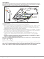
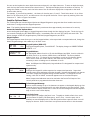
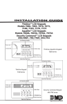
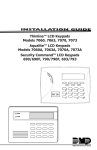
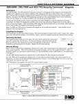
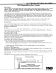
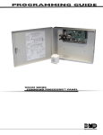
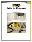
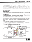
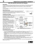
Installation Guide 7760 LCD Glass Keypad Description The DMP Model 7760 LCD Glass Keypad offers the same functionality and flexible features as standard DMP keypads. The contemporary glass touch design offers an elegant, sleek look to accent any decor. Each 7760 keypad provides a 32‑character touchscreen backlit display, keyboard with easy-to-read lettering, three Panic icons, a multi-functional AC Power/Armed LED, and an internal speaker. Installing the Keypad The keypad housing is designed to easily install using two #6 screws on a flat surface or optional 778 backplate. The keypad housing is made up of two parts: a hinged cover and a base which contains the circuit board, glass touchscreen, and keyboard components. A single 4-wire harness is used to connect the 7760 to the keypad bus of a DMP control panel. Figure 2 shows the back of the keypad with the 4-wire harness connected. Remove the Cover Use the following steps and Figures 1 and 2 to remove the hinged keypad cover. 1.Insert a flat screwdriver into one of the slots on the bottom of the keypad and gently lift the screwdriver handle toward you while pulling the halves apart. Repeat with the other slot. building Wall glass Keypad Front 778 backplate Legs Lift screwdriver handle up toward you to separate keypad cover from base. 2.Using your screwdriver, gently separate the left and right sides of the cover by applying slight inward pressure along the seam to disengage the internal side snaps. 3.Gently lift the cover and remove from the four cover hinges at the top and set aside. Figure 1: Loosen bottom of cover Figure 2: Loosen side of cover Install the Base Use the following steps to install the keypad base. Cut off the template below to use for mounting. 1.Place the template on the wall where the keypad is to be mounted and level using the horizontal alignment line. 2.Mark the two #6 screw locations and the wiring harness opening locations on the wall. 3.Install the two supplied #6 wall anchors where marked. 4.Drill a wiring harness hole no larger than 1/4” in diameter where indicated. Feed the 4-conductor wire through the created opening. Note: Make sure the wire harness opening is small enough to be covered by the keypad base. 5.Connect the 4-wire harness to the 4-conductor Keypad bus wire from the wall. 6.Gently plug the 4-wire harness connector onto the 4-pin header through the opening in the back of the keypad. See Figure 3. 7.Mount the 7760 keypad base to the #6 wall anchors using the provided #6 screws. Replace the Cover Use the following steps to reinstall the keypad cover. 1.Gently realign the top four hinges and set the cover into place. 2.Lower the cover and gently snap the two bottom latches and two internal side latches into place by squeezing the base and cover together to reduce the stress on the legs. (See Figure 3) Mounting Template ✁ Cut along dotted line and use as a drill template to create mounting and wiring holes. #6 Screw Location #6 Screw Location drill 1/4" hole for the Wiring harness * * horizontal alignment Line * Harness Wiring Figure 3 shows wiring harness mounting location and wiring assignments. Observe wire colors when connecting the Red, Yellow, Green, and Black wires to the keypad bus. When wiring directly to the panel terminals, connect Red to panel terminal 7, Yellow to terminal 8, Green to 9, and Black to panel terminal 10. to panel Keypad bus aC/armed Led Cover hinge (4) building Wall plug 4-Wire harness into J4 header glass Keypad Front Surface Mounting Screws (2) glass Keypad rear Leg Legs (2) Red – Keypad power Yellow – Send data Green – receive data Black – ground Squeeze latches to connect keypad cover to back. Figure 3: Keypad Side Mounting and Back Showing Wiring Harness Assignments Wiring Specifications When planning a keypad bus installation, keep in mind the following specifications: 1. DMP recommends using 18 or 22-gauge unshielded wire for all keypad and LX-Bus circuits. Do Not use twisted pair or shielded wire for LX-Bus and keypad bus data circuits. To maintain auxiliary power integrity when using 22-gauge wire do not exceed 500 feet. When using 18-gauge wire do not exceed 1,000 feet. Install an additional power supply to increase the wire length or add devices. 2. Maximum distance for any one circuit (length of wire) is 2,500 feet regardless of the wire gauge. This distance can be in the form of one long wire run or multiple branches with all wiring totaling no more than 2,500 feet. As wire distance from the panel increases, DC voltage on the wire decreases. 3. Each panel allows a specific number of supervised keypads. Additional keypads can be added in the unsupervised mode. Refer to the panel installation guide for the specific number of supervised keypads allowed. 4. Maximum voltage drop between the panel (or auxiliary power supply) and any device is 2.0 VDC. If the voltage at any device is less than the required level, add an auxiliary power supply at the end of the circuit. When voltage is too low, the devices cannot operate properly. Refer to the LX-Bus/Keypad Bus Wiring Application Note (LT-2031). Also see the 710/710F Module Installation Sheet (LT-0310) for more information. Additional Power Supply If the current draw for all keypads exceeds the panel output, you can provide additional current by adding a Model 505-12 auxiliary power supply. Connect all keypad Black ground wires to the power supply negative terminal. Run a wire from the power supply negative terminal to the panel common ground terminal 10. Connect all keypad Red power wires to the power supply positive terminal. Do NOT connect the power supply positive terminal to any panel terminal. Refer to the 504-24 and 505-12 Power Supply Installation Guide (LT-0453) for more information. Digital Monitoring Products 2 7760 Keypad Installation Guide Keypad Bus Monitor For Fire Protective systems, the 893/893A Module must be installed in the XR500 Series or XR200 control panel to monitor the keypad bus and sound an audible trouble whenever the keypad bus fails to operate. Refer to the 893/ 893A Module Installation Sheet (LT-0135). Touchscreen Display The 7760 is an integrated LCD with a touchscreen user interface that can be programmed to turn off (clear glass) during periods when the keypad is not in use. See Backlighting Brightness under End-User Options. Touch the area over each key, icon, or other selection to operate the keypad. Warning: DO NOT use any sharp objects to operate the touchscreen such as a pen or pencil. aC power/armed Led 32-Character display with Four touch Select areas data entry Keyboard Logo three panic icons (Optional) back arrow Key COMMand Key Figure 4: 7760 LCD Glass Keypad Keypad Backlighting The touchscreen illuminates at full brightness any time the glass is touched. When the speaker is sounding, the backlight illuminates at one-half (1/2) brightness. During an alarm condition, the backlight turns Red. When all alarm conditions are cleared from the display, the Red backlight returns to Blue and the user‑selected brightness. This user selected brightness may be set to off which allows the glass graphic display to turn off (clear glass). Simply touch the glass anywhere and the backlight illuminates for data entry. AC Power/Armed LED Operation The LED indicates the Power and Armed status of the panel. Depending on the operation, the LED displays in Red or Blue as listed in the table. Color and Activity Blue Steady Blue Blinking No Light Red Steady Red/Blue Alternate Red Blinking Operation Panel Disarmed, AC Power OK, Battery OK Panel Disarmed, AC Power OK, Battery Fault Panel Disarmed, AC Power Fault, Battery OK Panel Armed, AC Power OK, Battery OK Panel Armed, AC Power OK, Battery Fault Panel Armed, AC Power Fault, Battery OK Panic Icons All 7760 keypads offer an optional Panic function that allows users to send Panic, Emergency, or Fire reports to the central station. You must enable the Panic function in Installer Options in order to use the Panic Icons. See Programming Keypad Options later in this document. The Panic Icons are shown in Figure 5. Police Emergency Fire Figure 5: Panic Icons The user must touch and hold the Icon for two seconds until a beep from the keypad is heard. At the beep, the panel sends the following zone alarm reports to the central station: Panic (Police Icon) - Zone 19 + Device Address Emergency - non-medical (Exclamation Point Icon) - Zone 29 + Device Address Fire (Flame Icon) - Zone 39 + Device Address 7760 Keypad Installation Guide Digital Monitoring Products 3 Internal Speaker Operation The Glass keypad emits standard tones for key touches, entry delay, and system alerts. The speaker also provides distinct burglary, fire, zone monitor, and prewarn cadences. The keypad provides an alternate prewarn entry delay cadence that occurs when the keypad is displaying a zone alarm. End-User Options The 7760 Keypads provide three adjustments the end-user can make through a User Options Menu. The user can also view the keypad model number and address in User Options. To access User Options, touch and hold the center of the logo for two seconds. The 32-character display changes to SET BRIGHTNESS. Touch the CMD (COMMAND) key to display the next option or touch the <— (Back Arrow) to exit the User Options function. See Figure 5. Note: The End-User Options function automatically terminates after approximately 20 seconds of no activity. Backlighting Brightness Set brightness Set the backlight illumination and AC Power/Armed LED brightness level. In the < > touchscreen display below SET BRIGHTNESS, touch the left < to lower the backlight brightness and the right > to raise the backlight brightness. If the brightness level is lowered, it reverts to maximum intensity whenever the glass is touched during normal operation. If the glass is not touched, and the speaker has not sounded for 30 seconds, the user-selected standby brightness level restores. Note: If the brightness level is set to the lowest level, after 30 seconds of no activity, the screen display turns off and will vanish from sight. Simply touch the glass anywhere and the display and backlight illuminates. < Set TONE Speaker Tone Set the keypad speaker tone. At the SET TONE display, use the left < to lower the tone > and the right > to raise the tone. Volume Level Set VOLUME LEVEL Set the keypad speaker volume level for key touches and entry delay tone conditions. < > During alarm and trouble conditions, the volume is always at maximum level. Use the left < to decrease the keypad volume and the right > to increase the volume. Model Number Model number The LCD displays the keypad model number and the keypad firmware version and date. 7760v100 030805 The user cannot change this information. Keypad address 01 Keypad Address The LCD displays the current keypad address. While in User Options, the user cannot change the keypad address. Touch the (<— ) Back Arrow key to exit the User Options function. Entering Characters Figure 6 shows the location of the alpha and non-alphanumeric characters and the 32-character display areas to touch to enter information. The non-alpha special characters do not display on the keyboard but are listed on Figure 5 for reference. The special characters available are as follows starting with the 1 digit key to the 9 digit key: ( ) ! ? / & $ ‚ ’ and - . * # for the 0 key. Second Letter Select area 2 First Letter Select area 1 third Letter Select area 3 Keyboard keys Special Character Select area 4 abC( deF) ghi! 32-Character Display JKL? MnO/ pQr& StU$ VWX, yZ ' touch 9 Key and Select area 3 to enter a blank space in the text. (SpaCe) Panic Icons back arrow Key –.*# COMMand Key Figure 6: Entering Alpha and Non-Alpha Characters Digital Monitoring Products 4 7760 Keypad Installation Guide You can use the keyboard to enter alpha characters and special, non-alpha characters. To enter an alpha character, touch the key that has the desired letter shown below it. The keyboard display shows the number on that key. To change the number to a letter, touch the Select area of the 32-character display that corresponds to the letter location under the key. For example, if you touch key number 1, the letters for that key are A, B, and C. Touch Select Area 1 for A, Select Area 2 for B, Select Area 3 for C, and Select Area 4 for the special character. Enter a space by touching 9 then the Select Area 3. Refer to Figure 6 as needed. Installer Options Menu The 7760 keypad also contains Keypad Options and Keypad Diagnostics programs that allow installers and service technicians to configure and test keypad operation. Note: The Installer Options function automatically terminates after approximately two minutes of no activity. Access the Installer Options Menu Access the Keypad Options Menu or Keypad Diagnostics Menu through the User Options function. Touch the Logo for two seconds to display the SET BRIGHTNESS option. Immediately enter the code 3577 (INST) and touch CMD. The display changes to KPD OPT (keypad options), KPD DIAG (keypad diagnostics) and STOP. Keypad Options The Keypad Options menu allows you to set the keypad address, select supervised or unsupervised mode, change the default keypad message, and enable any or all Panic Icons. Keypad Options (KPD OPT) KPD KPD To program keypad options, touch KPD OPT. The display changes to CURRENT KEYPAD OPTDIAG STOP ADDRESS: # #. CURRENT KEYPAD ADDRESS: 01 Keypad Address Set the keypad address from 01 to 05 with the XRSuper6 and XR20, from 01 to 08 with the XR40, and 01 to 16 with the, XR500 Series, and XR2500F. The factory default address is set at 01. To change the current address, touch any 32-character display Select area to clear the current address, then enter the new address. It is not necessary to enter a leading zero for addresses 01 to 09. Note: On XRSuper6 and XR20 panels, keypad Address 5 is designated for unsupervised operation only. Keypad Mode KEYPAD MODE: Configure the keypad for either supervised or unsupervised operation. Supervised *SUPUNSUP keypads cannot share addresses with other keypads. Unsupervised keypads can operate with other unsupervised keypads sharing the same address. To change the current setting, touch SUP or UNSUP. An asterisk appears next to the selected option. Note: Unsupervised addresses cannot be used when the Device Fail Output of the control panel has a programmed value other than zero. DEFAULT KEYPAD MSG: Default Keypad Message Enter a custom message of up to 16-characters to appear on the keypad display top line whenever that line is not being used for any other purpose by the control panel. Touch any 32-character display Select area to clear the current message and use the keyboard keys to enter a new custom display. Arm panic keys: *PN *em *FI 7760 Keypad Installation Guide Arm Panic Icons Use this option to configure the Panic Icons. To enable or disable a Panic Icon, touch the icon name: PN (Panic), EM (Emergency), and FI (Fire). Once the panic icon is enabled, an asterisk displays next to the description and the respective Panic icon will display for the user. Refer to the Panic Icon Options section earlier in this document. Digital Monitoring Products 5 Keypad Diagnostics The Keypad Diagnostics menu allows installers and technicians to test keypad operation. Keypad Diagnostics (KPD DIAG) KPD KPD The Keypad Diagnostic option allows you to check the display segments, check the OPTDIAG STOP keyboard backlighting, and test individual keys. Touch KPD DIAG. The keypad turns on all of the 32-character display segments and illuminates the Blue backlighting. A few seconds later the keypad turns the Blue lighting off and illuminates Red. The keypad then alternates between these two states. Touch CMD at any time to continue. Test Individual Keys The display changes to PRESS KEY TO TEST. This option allows you to test each key on the keyboard to ensure it is operating properly. Touch and hold each key for about two seconds. The key number being held appears in the display. Verify the correct number displays before testing the next key. The Panic icons will display for test even if they are not enabled for standard operation. The four distinct Select areas of the 32-character display can also be tested and will be displayed as Top 1, Top 2 Top 3, and Top 4. Exiting the Installer Options When done, touch the CMD key once to return to the Installer Options screen. Touch STOP to exit the Installer Options function. Press key to Test Cleaning the Glass Display Clean the Glass touchscreen using a water dampened soft lint-free cloth. Apply the water onto the cloth, do NOT apply directly onto the Glass touchscreen. After cleaning, wipe the touchscreen dry with a dry soft lint-free cloth. FCC Information This device complies with Part 15 of the FCC Rules. Operation is subject to the following two conditions: (1) This device may not cause harmful interference, and (2) this device must accept any interference received, including interference that may cause undesired operation. Changes or modifications made by the user and not expressly approved by the party responsible for compliance could void the user’s authority to operate the equipment. NOTE: This equipment has been tested and found to comply with the limits for a Class B digital device, pursuant to part 15 of the FCC Rules. These limits are designed to provide reasonable protection against harmful interference in a residential installation. This equipment generates, uses and can radiate radio frequency energy and, if not installed and used in accordance with the instructions, may cause harmful interference to radio communications. However, there is no guarantee that interference will not occur in a particular installation. If this equipment does cause harmful interference to radio or television reception, which can be determined by turning the equipment off and on, the user is encouraged to try to correct the interference by one or more of the following measures: - Reorient or relocate the receiving antenna. - Increase the separation between the equipment and receiver. - Connect the equipment into an outlet on a circuit different from that to which the receiver is connected. - Consult the dealer or an experienced radio/TV technician for help. Operating Range Normal Standby Alarm Dimensions Touch Durability Accessories Compatibility 9.5 VDC to 14 VDC 65mA 115mA 6.9” W x 4.75” H x 1.4” D 50 million touches in a single pixel 4-wire Harness Model 300 (included) Keypad Backplate Model 778 Model 778L All DMP Command Processor™ panels. Listings and Approvals FCC Part 15 Underwriters Laboratories (UL) Listed UL 365 Police Connected Burglar UL 609 Local Burglar UL 1023 Household Burglar UL 1076 Proprietary Burglar UL 1610 Central Station Burglar UL 985 Household Fire Warning 800-641-4282 INTRUSION • FIRE • ACCESS • NETWORKS www.dmp.com 2500 North Partnership Boulevard Made in the USA Springfield, Missouri 65803-8877 LT-0851 1.01 © 2008 Digital Monitoring Products, Inc. 8062 Specifications