1
User Guide
Audio Products
Mixers and Processors
DMP 128
Digital Matrix Processor
68-2036-01 Rev. C
08 13
Safety Instructions
Safety Instructions • English
WARNING: This symbol,
, when used on the product, is intended to
alert the user of the presence of uninsulated dangerous voltage within
the product’s enclosure that may present a risk of electric shock.
Chinese Simplified(简体中文)
警告:
产品上的这个标志意在警告用户该产品机壳内有暴露的危险
电压,有触电危险。
注 意:
ATTENTION: This symbol,
, when used on the product, is intended to alert
the user of important operating and maintenance (servicing) instructions in the
literature provided with the equipment.
For information on safety guidelines, regulatory compliances, EMI/EMF
compatibility, accessibility, and related topics, see the Extron Safety and
Regulatory Compliance Guide, part number 68-290-01, on the Extron
website, www.extron.com.
Instructions de sécurité • Français
avertissement: Ce pictogramme,
, lorsqu’il est utilisé sur le
produit, signale à l’utilisateur la présence à l’intérieur du boîtier du
produit d’une tension électrique dangereuse susceptible de provoquer
un choc électrique.
attention: Ce pictogramme,
, lorsqu’il est utilisé sur le produit,
signale à l’utilisateur des instructions d’utilisation ou de maintenance
importantes qui se trouvent dans la documentation fournie avec le
matériel.
Pour en savoir plus sur les règles de sécurité, la conformité à la
réglementation, la compatibilité EMI/EMF, l’accessibilité, et autres sujets
connexes, lisez les informations de sécurité et de conformité Extron, réf. 68290-01, sur le site Extron, www.extron.fr.
产 品 上 的 这个 标 志 意 在 提 示用 户设 备 随 附 的 用 户手 册 中 有
重要的操作和维护(维修)说明。
关于我们产品的安全指南、遵循的规范、EMI/EMF 的兼容性、无障碍
使用的特性等相关内容,敬请访问 Extron 网站 www.extron.cn,参见 Extron
安全规范指南,产品编号 68-290-01。
Chinese Traditional(繁體中文)
警告:
注意
Vorsicht: Dieses Symbol
auf dem Produkt soll dem Benutzer
in der im Lieferumfang enthaltenen Dokumentation besonders
wichtige Hinweise zur Bedienung und Wartung (Instandhaltung)
geben.
Weitere Informationen über die Sicherheitsrichtlinien, Produkthandhabung,
EMI/EMF-Kompatibilität, Zugänglichkeit und verwandte Themen finden Sie
in den Extron-Richtlinien für Sicherheit und Handhabung (Artikelnummer 68290-01) auf der Extron-Website, www.extron.de.
若產品上使用此符號,是為了提醒使用者。
有關安全性指導方針、法規遵守、EMI/EMF 相容性、存取範圍和相關主題的詳細
資訊,請瀏覽 Extron 網站:www.extron.cn,然後參閱《Extron 安全性與法規遵
守手冊》,準則編號 68-290-01。
Japanese
警告: この記号
が製品上に表示されている場合は、筐体内に絶縁されて
いない高電圧が流れ、感電の危険があることを示しています。
Sicherheitsanweisungen • Deutsch
warnung: Dieses Symbol
auf dem Produkt soll den Benutzer darauf
aufmerksam machen, dass im Inneren des Gehäuses dieses Produktes
gefährliche Spannungen herrschen, die nicht isoliert sind und die einen
elektrischen Schlag verursachen können.
若產品上使用此符號,是為了提醒使用者,產品機殼內存在著
可能會導致觸電之風險的未絕緣危險電壓。
注意: この記号
が製品上に表示されている場合は、本機の取扱説明書に
記載されている重要な操作と保守(整備)の指示についてユーザーの
注意を喚起するものです。
安全上のご注意、法規厳守、EMI/EMF適合性、その他の関連項目に
ついては、エクストロンのウェブサイトwww.extron.jp より
『 Extron Safety and Regulatory Compliance Guide 』(P/N 68-290-01) をご覧ください。
Korean
경고: 이 기호
, 가 제품에 사용될 경우, 제품의 인클로저 내에 있는
접지되지 않은 위험한 전류로 인해 사용자가 감전될 위험이 있음을
경고합니다.
Instrucciones de seguridad • Español
Este símbolo,
, cuando se utiliza en el producto,
avisa al usuario de la presencia de voltaje peligroso sin aislar dentro
del producto, lo que puede representar un riesgo de descarga
eléctrica.
ADVERTENCIA:
ATENCIÓN: Este símbolo,
, cuando se utiliza en el producto, avisa
al usuario de la presencia de importantes instrucciones de uso
y mantenimiento recogidas en la documentación proporcionada
con el equipo.
Para obtener información sobre directrices de seguridad, cumplimiento
de normativas, compatibilidad electromagnética, accesibilidad y temas
relacionados, consulte la Guía de cumplimiento de normativas y seguridad de
Extron, referencia 68-290-01, en el sitio Web de Extron, www.extron.es.
주의:
이 기호
, 가 제품에 사용될 경우, 장비와 함께 제공된 책자에 나와
있는 주요 운영 및 유지보수(정비) 지침을 경고합니다.
안전 가이드라인, 규제 준수, EMI/EMF 호환성, 접근성, 그리고 관련
항목에 대한 자세한 내용은 Extron 웹 사이트(www.extron.co.kr)의
Extron 안전 및 규제 준수 안내서, 68-290-01 조항을 참조하십시오.
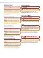
FCC Class A Notice
This equipment has been tested and found to comply with the limits for a Class A digital device,
pursuant to part 15 of the FCC rules. The Class A limits provide reasonable protection against harmful
interference when the equipment is operated in a commercial environment. This equipment generates,
uses, and can radiate radio frequency energy and, if not installed and used in accordance with the
instruction manual, may cause harmful interference to radio communications. Operation of this
equipment in a residential area is likely to cause interference; the user must correct the interference at
his own expense.
NOTE: For more information on safety guidelines, regulatory compliances, EMI/EMF compatibility,
accessibility, and related topics, see the “Extron Safety and Regulatory Compliance
Guide” on the Extron website.
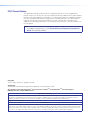
Copyright
© 2013 Extron Electronics. All rights reserved.
Trademarks
All trademarks mentioned in this guide are the properties of their respective owners.
The following registered trademarks®, registered service marks(SM), and trademarks(TM) are the property of
RGB Systems, Inc. or Extron Electronics:
Registered Trademarks (®)
AVTrac, Cable Cubby, CrossPoint, eBUS, EDID Manager, EDID Minder, Extron, Flat Field, GlobalViewer, Hideaway, Inline, IP Intercom, IP Link,
Key Minder, LockIt, MediaLink, PlenumVault, PoleVault, PowerCage, PURE3, Quantum, SoundField, SpeedMount, SpeedSwitch, System
Integrator, TeamWork, TouchLink, V‑Lock, VersaTools, VN‑Matrix, VoiceLift, WallVault, WindoWall, XTP and XTP Systems
Registered Service Mark(SM) : S3 Service Support Solutions
Trademarks (™)
AAP, AFL (Accu‑Rate Frame Lock), ADSP (Advanced Digital Sync Processing), AIS (Advanced Instruction Set), Auto‑Image, CDRS (Class D
Ripple Suppression), DDSP (Digital Display Sync Processing), DMI (Dynamic Motion Interpolation), Driver Configurator, DSP Configurator, DSVP
(Digital Sync Validation Processing), FastBite, FOXBOX, IP Intercom HelpDesk, MAAP, MicroDigital, ProDSP, QS-FPC (QuickSwitch Front Panel
Controller), Scope‑Trigger, SIS, Simple Instruction Set, Skew‑Free, SpeedNav, Triple‑Action Switching, XTRA, ZipCaddy, ZipClip
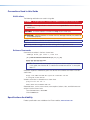
Conventions Used in this Guide
Notifications
The following notifications are used in this guide:
DANGER: A danger indicates a situation that will result in death or severe injury.
WARNING: A warning indicates a situation that has the potential to result in death or
severe injury.
CAUTION: A caution indicates a situation that may result in minor injury.
ATTENTION: Attention indicates a situation that may damage or destroy the product or
associated equipment.
NOTE: A note draws attention to important information.
TIP: A tip provides a suggestion to make working with the application easier.
Software Commands
Commands are written in the fonts shown here:
^AR Merge Scene,,Op1 scene 1,1 ^B 51 ^W^C
[01] R 0004 00300 00400 00800 00600 [02] 35 [17] [03]
E X! *X1&* X2)* X2#* X2! CE}
NOTE: For commands and examples of computer or device responses mentioned
in this guide, the character “0” is used for the number zero and “O” is the capital
letter “o.”
Computer responses and directory paths that do not have variables are written in the font
shown here:
Reply from 208.132.180.48: bytes=32 times=2ms TTL=32
C:\Program Files\Extron
Variables are written in slanted form as shown here:
ping xxx.xxx.xxx.xxx —t
SOH R Data STX Command ETB ETX
Selectable items, such as menu names, menu options, buttons, tabs, and field names are
written in the font shown here:
From the File menu, select New.
Click the OK button.
Specifications Availability
Product specifications are available on the Extron website, www.extron.com.
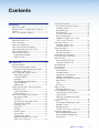
Contents
Introduction ........................................................... 1
About This Guide................................................. 1
About the DMP 128 Digital Matrix Processor....... 1
Features.............................................................. 1
DMP 128 Application Diagram............................. 4
Installation .............................................................. 5
Mounting the DMP 128....................................... 5
DMP 128 Models................................................ 5
Hardware Configuration....................................... 5
Rear Panel Features and Cabling......................... 6
USB Configuration Port (Front Panel)................... 9
Front Panel Indicators.......................................... 9
Reset Actuator and LED.................................... 10
Hardware Reset Modes:................................ 10
Digital I/O Ports............................................. 11
DMP Software...................................................... 12
Software Control............................................... 12
Windows-based Program Control...................... 13
Installing the DSP Configurator Program........ 13
Installing the USB Driver................................ 15
DSP Configurator Program Basics..................... 16
Starting the program..................................... 16
Using the program......................................... 16
Navigation..................................................... 20
DSP Configurator Toolbar Menus................... 21
Presets drop-down....................................... 26
Mode buttons ............................................... 26
Audio level, Mix‑point, Processing Blocks,
and Signal Chains............................................. 27
Level Control Blocks...................................... 28
Processor blocks.......................................... 28
Mic/Line Input Signal Chain Controls................. 30
Gain Control (GAIN)....................................... 30
Filter (FILT)..................................................... 30
Acoustic Echo Cancellation (AEC) ................. 40
Advanced AEC Controls................................ 43
Dynamics (DYN)............................................ 44
Delay (DLY).................................................... 49
Ducking ........................................................ 50
Ducker Tutorials............................................. 53
Automix (AM)................................................. 54
Pre‑mixer Gain (GAIN) ................................... 57
Telephone Rx (DMP 128 C P and
DMP 128 C P AT only).................................. 58
Line Output Channels........................................ 58
Post-mixer Trim Control (TRIM) ..................... 58
Loudness (LOUD).......................................... 58
Delay Block (DLY) ......................................... 61
Filter Block (FILT) .......................................... 61
Dynamics block (DYN) .................................. 61
Volume Control (VOL) .................................. 62
Telephone Tx (DMP 128 C P and
DMP 128 C P AT only).................................. 62
Virtual Bus Returns............................................ 63
Virtual Bus Returns, A-D................................ 63
Virtual Bus Returns, E-H................................ 68
Output Mix Matrix.............................................. 69
Mix‑point Behavior:........................................ 71
Mix-point Examples....................................... 73
Virtual Send Bus Mix Matrix............................... 76
Expansion Outputs Mix Matrix........................... 78
Extron EXP Bus................................................. 79
Connecting the EXP Ports............................. 79
Using the Expansion Bus............................... 80
Device Manager................................................ 81
AT (Dante) Bus ................................................. 81
Group Masters.................................................. 82
Group Members............................................ 82
Grouped Controls.......................................... 82
Configuring a Group Master........................... 84
Deleting a Group Master................................ 85
Viewing and Using a Group Master................ 85
Add a Group.................................................. 85
Tools.............................................................. 86
Soft Limits..................................................... 87
Digital I/O Ports................................................. 88
Reinitialize Digital I/O...................................... 89
Emulate Mode and Live Mode........................... 89
Synchronizing: Pull from or Push
to the Device................................................ 89
Selecting Live Mode and Pushing
or Pulling Data.............................................. 90
Presets.............................................................. 93
Previewing and Recalling a Preset................. 93
Building a Preset............................................ 94
Managing Presets.......................................... 95
Presets: Pull, Push, or Create Live................. 96
Protected Configuration..................................... 96
Save Protected Configuration........................ 96
Recall Protected Configuration...................... 96
Change PIN................................................... 96
DMP 128 • Contents
v
DSP Configurator Windows Menus................... 97
Keyboard Navigation..................................... 97
Optimizing Audio Levels.................................. 100
About Setting Gain Structure....................... 101
Setting Input Gain........................................ 102
Setting a Nominal Output Level................... 102
Adjusting Trim.............................................. 103
Adjusting Pre-mixer Gain............................. 103
Setting Output Gain Structure...................... 103
Setting Mic/Line Input and Mix Levels.......... 104
Adjusting Trim.............................................. 104
Setting Volume Control for the
Amplifier Stage........................................... 104
Signal Path Building Blocks............................. 105
Adding a Building Block............................... 107
Organize Building Blocks............................. 109
Dante Installation and Operation
(AT Models Only)................................................ 112
DMP 128 AT Bus............................................. 112
Dante Controller Software Installation.............. 113
Dante Network Audio Setup........................ 113
Dante Device Discovery............................... 115
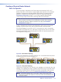
Creating a Physical Dante Network.................. 116
Basic Configuration..................................... 116
Redundant Configuration............................. 117
Managing Network Traffic............................ 117
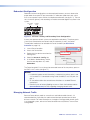
Dante Controller Configuration......................... 118
Start Dante Controller.................................. 118
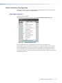
Rename a Dante Device.............................. 120
AT Expansion Bus Organization................... 120
Rename an Input or Output......................... 121
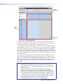
Selecting Inputs and Outputs for Dante........... 122
DMP 128P AT Bus Outputs......................... 122
DMP 128P AT Expansion Bus (AT Inputs).... 123
Signal Routing with Dante................................ 124
Using the Extron Expansion Bus
with DMP 128 AT Devices.............................. 125
Viewing AT Channels with AT Meters............... 125
Telephone Interface.......................................... 126
Telephone Configuration.................................. 126
Telephone Dialer.............................................. 127
Third Party Control of the Phone Dialer............ 128
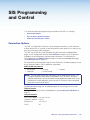
SIS Programming and Control....................... 129
Connection Options......................................... 129
RS-232 Port................................................ 130
USB Port (Front Panel)................................. 130
Ethernet (LAN) Port...................................... 130
Verbose Mode............................................. 131
Host-to-device Communications..................... 132
DMP 128-initiated Messages....................... 132
Password Information.................................. 132
Using the Command and
Response Tables........................................ 132
Symbol definitions....................................... 133
Error Responses.......................................... 133
Simple Control Port Commands Telnet and Web-browser Accessible........... 134
Command and Response Tables..................... 135
Basic SIS Commands.................................. 135
DSP SIS Commands................................... 141
Symbol Definitions....................................... 142
Special Characters...................................... 142
Setting Audio Levels.................................... 148
HTML Operation................................................ 155
Download the Startup Page............................. 155
Status Tab....................................................... 157
System Status Page.................................... 157
Configuration Tab............................................ 157
System Settings Page................................. 157
Passwords Page......................................... 160
Firmware Upgrade Page.............................. 161
File Management Tab...................................... 164
File Management Page................................ 164
Special Characters.......................................... 164
Reference Information..................................... 165
Mounting the DMP 128................................... 165
Tabletop Use............................................... 165
UL Rack Mounting Guidelines...................... 165
Rack Mounting............................................ 166
Table or Wall Mounting................................. 167
Firmware Loader............................................. 168
DMP 128 Hardware Reset Modes................... 169
DSP SIS Commands for Mix-point Level
and Mute Control........................................... 170
Selecting Mix-points.................................... 171
Signal Routing............................................. 171
Setting Audio Levels.................................... 172
SIS Command and Response Table
for DSP Mix-point and Level Control........... 173
SIS Command Mix-points................................ 174
Output Mixer .............................................. 175
Virtual Sends Bus Mix Matrix....................... 185
EXP Outputs ............................................... 195
DMP 128 • Contents
vi
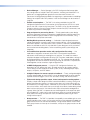
Introduction
This section describes this user guide and the DMP 128, including:
•
About This Guide
•
About the DMP 128 Digital Matrix Processor
•
Features
•
DMP 128 Application Diagram
About This Guide
This guide contains installation, configuration, and operating information for the
Extron Electronics DMP 128 ProDSP Digital Matrix Processor, software controlled digital
audio processor.
In this manual, the DMP 128 may also be referred to as “the mixer” or “device.”
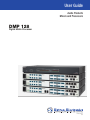
About the DMP 128 Digital Matrix Processor
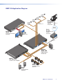
The Extron DMP 128 Digital Matrix Processor is a 12x8 audio mixer featuring
Extron ProDSP, automixing, and I/O expansion capabilities, and is available with
AEC - acoustic echo cancellation plus Dante™ audio networking. The DMP 128 offers
a configuration approach to DSP to simplify mixing, routing, conferencing, and room
optimization. Quick and intuitive configuration using the DSP Configurator™ Software allows
DMP 128 installation in very little time, with easy-to-learn adjustments heard in real-time.
A digital audio expansion port allows two DMP 128 units to be linked together to expand
input and output signal management and routing capabilities. The DMP 128 is ideal for
presentation and conferencing applications in boardrooms, courtrooms, and conference
centers that require advanced matrix mixing with DSP.
The DMP 128 has no front panel controls. All configuration is performed using the
Extron DSP Configurator program from a host computer via any of the communication
ports; RS-232, USB, or Ethernet (high-speed ports recommended). Signal presence and
clip LEDs for the twelve input channels and eight output channels are on the front panel.
Features
•
Six models with 12 mic/line inputs, 8 outputs and Extron EXP expansion bus
include:
•
DMP 128 — 12x8 ProDSP processor base unit
•
DMP 128 C — 12x8 ProDSP processor with AEC
•
DMP 128 AT — 12x8 ProDSP processor with Dante
•
DMP 128 C AT — 12x8 ProDSP processor with AEC and Dante
•
DMP 128 C P — 12x8 ProDSP processor with AEC and Phone (POTS) interface
•
DMP 128 C P AT — 12x8 ProDSP processor with AEC, Phone (POTS) interface,
and Dante
DMP 128 • Introduction
1
•
Inputs —
Twelve balanced or unbalanced mic/line level on 3.5 mm, 3-pole and
6-pole captive screw connectors, eight with phantom power.
•
Outputs —
Eight balanced or unbalanced line level on 3.5 mm, 6-pole captive screw
connectors.
•
Eight channels of acoustic echo cancellation (AEC) —
The DMP 128 C models
include eight independent channels of high performance AEC, as well as selectable
noise cancellation. Extron AEC features advanced algorithms that deliver fast echo
canceler convergence for optimal intelligibility in situations that challenge AEC
performance, including double-talk, and the use of wireless microphones at the near
end.
•
Dante™ Audio Networking — Dante equipped DMP 128P AT models provide
scalable audio transport over a local area network using standard Internet protocols.
Each DMP 128P AT sends out 24 channels of 24-bit/48 kHz digital audio and can
receive 56 channels over the network. A built-in four-port Gigabit switch provides
direct interconnection of multiple DMP 128P AT units to create larger, cost-effective
audio matrixes. Both Dante and the DMP 128P AT processor four-port switch are
AVB - Audio Video Bridging ready. Dante is a trademark of Audinate® Pty Ltd.
•
Digital audio expansion port for linking two DMP 128 units — An expansion
port allows any two DMP 128 models to be linked together via a single shielded
CAT 6 cable. This allows eight matrix mixes of the inputs, plus eight virtual paths to be
sent and received between units.
•
Automixer with eight gate groups — The DMP 128 features an automixer with
advanced features for managing signal levels from multiple microphones. The
automixer includes a gating mode that automatically gates channels on or off, as well
as a gain sharing mode that maintains the overall system gain based on the number
of active mics.
•
ProDSP audio signal processing — The DMP 128 features 32/64-bit floating point
audio DSP processing, which maintains very wide dynamic range and audio signal
transparency, to simplify management of gain staging while reducing the possibility of
DSP signal clipping.
•
48-volt phantom power — The DMP 128 is equipped with selectable 48-volt
phantom power for the first eight inputs, allowing the use of condenser microphones.
•
24-bit/48 kHz analog-to-digital and digital-to-analog converters — Fully
preserve the integrity of the original audio signal.
•
Fixed, low latency DSP processing — Input to output latency is low within
the DMP 128 and stays constant, regardless of the number of active channels or
processes. While latency increases marginally on channels with AEC enabled, overall
latency remains low. Fixed latency processing keeps audio in sync with video, and
prevents distractions to presenters or performers resulting from delayed live audio.
•
DSP Configurator Software — A powerful yet user-friendly PC-based software
tool for managing all audio operations of the DMP 128. It enables complete setup
and configuration of digital audio processing tools on the ProDSP platform, as well as
routing and mixing.
•
Intuitive Graphical User Environment — The DSP Configurator Software features
a graphical user environment that offers a clear view of all input and outputs, audio
processing blocks, routing, mix-points, and virtual routing in a single screen. This
allows a designer or installer to quickly view an audio configuration without having to
access multiple dialog boxes or menus.
DMP 128 • Introduction
2
•
Device Manager — Device Manager in the DSP Configurator Software enables
easy configuration of multiple Extron DSP products, including two linked DMP 128
processors, by toggling between graphical user environments for each unit.
Processors can be grouped into folders for organizing as separate rooms or buildings.
Settings for multiple Extron DSP products in the Device Manager can be saved to a
single file.
•
Flexible control options — The DMP 128 can be controlled using the DSP
Configurator Software and a PC connection to the Ethernet port, the RS-232 serial
port, or the USB 2.0 port on the front panel. The DMP 128 can also be controlled
through a control system with Extron Simple Instruction Set (SIS)™ commands, and
by accessing the internal Web pages.
•
Copy and paste for processing blocks — To help speed audio system design
and setup, parameter settings can be quickly copied between individual processing
blocks or identical groups of blocks within the graphical user environment, using
conventional cut-and-paste commands.
•
Building Blocks processor settings — A collection of pre-designed processor
settings optimized for a specific type of input or output device, such as microphones
and Extron speakers, with preset levels, filters, dynamics, and more. Flexible building
blocks are available on each I/O strip and allow system designers to fully customize
and save their own building blocks, further streamlining audio system design and
integration.
•
Live and Emulate operation modes with configuration file saving — Live
mode allows integrators to connect to the DMP 128 and make live parameter
adjustments while hearing or metering them in real-time. This avoids the need to
compile and upload a configuration file to the DSP. Emulation mode allows settings to
be configured offline, then uploaded to the DMP 128. The software also downloads
configuration files from the mixer for archiving. Settings for two DMP 128 processors
linked together can be saved to a single configuration file.
•
32 DSP Configurator presets — Using the DSP Configurator Software, any
parameters for DSP processing, levels, or audio routing can be saved as presets.
These settings can be saved for the entire system, or any selected group of inputs,
outputs, mix-points, and DSP blocks.
•
20 digital I/O ports for remote control or feedback — Twenty configurable digital
I/O ports are provided, so that the DMP 128 can be programmed to sense and then
respond to external triggers such as mic activation, muting, and recall of presets.
•
Triple matrix design provides output, virtual, and expansion routing options —
Employs a triple matrix design that offers substantial flexibility in routing, mixing, and
processing audio input sources. An output matrix allows any of the twelve inputs to
be mixed to any or all eight outputs. If desired, any of the inputs can first be directed
into a virtual matrix, which routes the inputs to eight virtual buses, before being mixed
back into the output matrix. Virtual buses allow inputs to be processed together as
a group. When two DMP 128 processors are linked together via the expansion ports
over shielded CAT 6 cable, inputs and virtual buses of one unit can be routed to the
other processor through an expansion matrix, for additional processing or matrix
mixing into the outputs.
•
Group masters — The DMP 128 provides the capability to consolidate gain or mute
control throughout the system. Gain or mute controls can be selected and added to a
group master, which can then be controlled by a single master fader or mute control.
Each group master can have up to 16 members, and up to 32 group masters can be
created.
DMP 128 • Introduction
3
DMP 128 Application Diagram
R
vC
D
Dv
C
DO
m
CA
TO
P
LAP
PC
ON
F
OF
Y
PLA
DIS TE
mU
EN
RE
SC
UP
EN
RE
SC WN
DO
UT
Desk
Microphones
-232
TP
OU
RS
A
B
L
R
L
6
DIO3
5
T
PU 4
8
IN
Extron
TLP 700Tv
7" TouchLink™
Tabletop
Touchpanel
R
7
AU
2
Ethernet
1
UT
TP
OU
TED
LIS 3
1T2 .
U S I.T.E
C
B
RG RY,
B-
Y
Y,
L
R
TCP/IP
Network
6
8
I
B
Dv
RG
B
7
Stereo
RG
3 YC
Y
R-
1 vID
z
60H
500v
-24
100
Y
B-
I
N
T
Extron
IPL 250
IP Link Ethernet
Control
Processor
5
Y
vID
P
U
4
2
Extron
IN1508
Scaling Presentation
Switcher
Laptop
Y
LA 2
RE
1
IR 2
m
CO
RX
TX
TX
PC
1
UT
INP 4
3
2
G
S
S
G
Y
LA 4
RE
3
IR 4
m
CO
RX
TX
N
LA
1
2
m1 SC TS
CO RT
RX
3
3
S
G
S
G
R
WE
PO
v
12 A
0m
50 X
mA
N
LA
RE
SE
T
RS-232
P
EX
L I/O
TA
GI
DI
6
4
1
3
11
2
12
3
13
4
14
5
16
2
7
17
8
18
9
19
10
-23
RS
20
Tx
Rx
15
2
1
O
U
T
P
U
T
S
10
8
7
6
5
Stereo
9
4
12
3
11
2
8
1
TS
7
PU
E IN
LIN
C/
MI
6
5
A
0V
0.6
MICV
+48
-24
100
3
2
1
4
8
7
6
5
60
Hz
50/
C
03
A 20
XP
Extron
DmP 128
-70v
G
IN
WIR
S 2 UTS
AS
CL OUTP
3
1
3
CH
Hz
80
TS
F
PU
OF
IN
3
2
1
L
vE
LE
Recording Device
Digital Matrix
Processor
4/8 2
F
HP
v
70
3
2
0
1
STANDBY
TImER DISABLE
TE
mO
RE
R/
ITE T
LIm EC
OT
PR
0
0
L
NA
SIG
60
50/
X
0v
-24 A mA
100 1.3
Hz
E
TIv Y
DB
- ACAN
N
EE - ST
GR BER
Am
ted
Lis
EO
T
S
17TDIO/vID
ATU
AUPAR
AP
Extron
XPA 2003C 70v
Combo Power Amplifier
Extron
SI 28
Surface-Mount
Speakers
Extron
SI 26CT
Two-Way Ceiling
Speakers
DMP 128 • Introduction
4
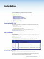
Installation
This section describes the installation of the DMP 128, including:
•
Mounting the DMP 128
•
DMP 128 Models
•
Hardware Configuration
•
Rear Panel Features and Cabling
•
USB Configuration Port (Front Panel)
•
Front Panel Indicators
•
Reset Actuator and LED
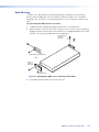
Mounting the DMP 128
The 1U high, full rack width, 8.5-inch deep DMP 128 Digital Matrix Processor can be:
•
Set on a table,
•
Mounted on a rack shelf,
•
Mounted under a desk or tabletop.
For detailed mounting options and UL rack mounting guidelines, (see
Mounting the DMP 128 on page 165).
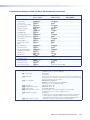
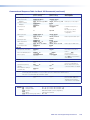
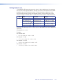
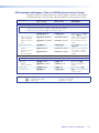
DMP 128 Models
There are six models of the DMP 128 available. Each model has a different feature set for
various applications.
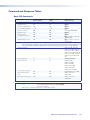
DMP 128 Model Matrix
The following feature matrix provides a breakdown of the various DMP 128 model
variations. Where differences occur in operation, they are noted in the text.
Model
Description
DMP 128
12x8 ProDSP Processor
DMP 128 C
12x8 ProDSP Processor with AEC
DMP 128 AT
12x8 ProDSP Processor with Dante Interface
DMP 128 C AT
12x8 ProDSP Processor with AEC, EXP Bus, and Dante Interface
DMP 128 C P
12x8 ProDSP Processor with EXP Bus, AEC, and Telephone modem
DMP 128 C P AT
12x8 ProDSP Processor with AEC, Telephone modem, EXP Bus, and
Dante Interface
Hardware Configuration
The DMP 128 does not have physical controls for configuration or operation.
The DMP 128 has several front and rear panel operational indicators and a rear panel
reset button for hardware resets outlined in the following pages.
DMP 128 • Installation and Operation
5
Rear Panel Features and Cabling
a
4
9
10
DMP 128 C AT
LINE
1
2
3
4
5
6
7
8
5
6
7
8
11
PHONE
12
1
2
3
4
5
6
7
8
1 2 3 4 5 G
11 12 13 14 15 G
b
c
d
l
e
k
AT
3
6 7 8 9 10 G
16 17 18 19 20 G
1
REMOTE
MIC/LINE INPUTS
50/60 Hz
2
MIC +48V
OUTPUTS
1
100-240V ~ 0.6A MAX
DIGITAL I/O
DMP 128 C AT
f
2
3
4
RS-232
Tx Rx G
g
RESET
EXP
LAN
h i j
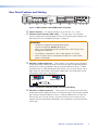
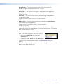
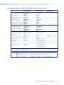
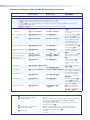
Figure 1. DMP 128 Rear Panel (DMP128 C P AT shown)
a Power connector — IEC power connector 100 to 240 VAC, 50 — 60 Hz
b Phantom Power indicators (MIC +48V) — LEDs light when +48 V phantom
power is placed on the corresponding mic/line input. Phantom power voltage is not
adjustable and is only available to Mic inputs 1 through 8.
ATTENTION:
• Condenser microphones require phantom power.
Dynamic microphones do not require power.
Never set an unbalanced dynamic microphone to +48V. Doing so may
damage the microphone.
• For condenser microphones, verify it safely operates at +48 VDC.
• When a line level source is connected, be certain the +48V phantom
power is off (cleared).
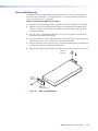
c Mic/Line 1-8 input connectors — Eight 3-pole 3.5 mm captive screw connectors
accept balanced or unbalanced mono mic or line level signals and provide phantom
power. Mic/line inputs provide gain settings to accommodate consumer (– 10 dBV)
and professional (+ 4 dBu) operating line level sources, plus mic level sources. Up to
eight mono mics or line inputs, balanced or unbalanced in any combination can be
connected to these
inputs,
(see
figure 2).
Audio
Input
Wiring
Tip
Ring
Sleeve
Tip
Sleeve
Balanced Input
Unbalanced Input
Do not tin the wires!
Figure 2. Balanced or Unbalanced Mic and Line Input Wiring
d Mic/Line 9-12 input connectors — Four 6-pole 3.5 mm captive screw connectors
accept balanced or unbalanced mono mic or line level signals. Mic/line inputs provide
gain settings to accommodate consumer (– 10 dBV) and professional (+ 4 dBu) line
Audio Output Wiring
level sources, plus mic level sources. Up to four mono mics or line inputs (or two
Tip
Tip
stereo
line inputs), balancedNOorGround
unbalanced
in any combination can be connected to
Here
Ring
Sleeve
Sleeve
these inputs.
Balanced Output
Unbalanced Output
Do not tin the wires!
DMP 128 • Installation and Operation
6
Do not tin the wires!
eMono output connectors — Four 6-pole 3.5 mm captive screw connectors provide
up to eight balanced
unbalanced
connections for mono line level output signals.
Audioor
Output
Wiring
Tip
Ring
Sleeve
Tip
NO Ground Here
Sleeve
Unbalanced Output
Balanced Output
Do not tin the wires!
ATTENTION: Connect the sleeve to ground ( ). Connecting the sleeve only to
a negative (– ) terminal will damage the audio output circuits.
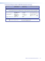
Figure 3. Output Connector Wiring
f Digital I/O output connectors — Four 6-pole 3.5 mm captive screw connectors
each provide five configurable digital input or output ports allowing connection of up
to twenty various devices such as motion detectors, alarms, lights, LEDs, buttons,
photo (light) sensors, temperature sensors, and other devices.
Digital I/O ports monitor or drive TTL level digital signals. The inputs can be configured
to operate in one of two modes: digital input or digital output. In output mode, the
device can source up to 250 mA at +5 V. In input mode, voltages greater than 1 V
indicate a logic ‘high’ signal while voltages less than 1 V indicate a logic ‘low’.
All digital I/O ports are tied to a common ground (one common ground for each
6-pole connector), but can be individually configured to operate in one of two modes:
digital input or digital output
NOTE: These ports can be configured via the DSP Configurator (see
Digital I/O Ports on page 88).
3"
(5
16
mm) MAX.
Do not tin the wires!
1
2
3
4
5
Digital I/O Wiring
Figure 4. Digital I/O Wiring
g RS-232 connector — One 3-pole 3.5 mm captive screw connector, labeled RS-232,
for bi-directional RS-232 (±5 V) serial control. Default baud rate is 38400. The RS-232
port is not intended to be used for configuring the DMP 128.
Tx Rx G
RS-232
Device
Do not tin
the wires!
Transmit (Tx)
Receive (Rx)
Ground ( G )
Bidirectional
Transmit (Tx)
Receive (Rx)
Ground (G)
Figure 5. RS-232 Wiring
DMP 128 • Installation and Operation
7
h EXP port connector — One RJ-45 jack for one additional DMP 128 connection.
The EXP connector has a green LED to indicate proper connection to an active
expansion network and a yellow LED that blinks to indicate data activity.
EXP
NOTE: A one foot shielded CAT 6 cable
is provided for the EXP connection.
LAN
RESET
Figure 6. EXP and LAN Connections
i LAN connector — A standard RJ-45 jack (see above) accepts a standard Ethernet
cable for network connection. The control system and DMP 128 must be connected
to the same network.
NOTE: To connect the DMP 128 directly to a computer Ethernet port, use a
crossover Ethernet cable.
•
A yellow (ACT) LED indicates data activity on the connection.
•
A green (Link) LED indicates the jack is connected properly to the network.
See SIS Programming and Control on page 129 for additional information on
Ethernet cabling.
j Reset button and LED indicator — The reset button returns the DMP 128
to different tiers of default states and can place the unit into an event
recording mode for troubleshooting. When using the reset function, the LED
LAN
flashes to signify the different tiers (see DMP 128 Hardware ResetEXP
Modes
on page 169). When not in reset mode, the LED operates as a power
indicator, duplicating the front panel LED operation.
RESET
k AT connections (AT models only) — Four RJ-45 jacks for Ethernet
connection form a 4-port Gigabit switch that interfaces with the AT bus. The AT
port expansion bus uses the Dante protocol for digital media networking allowing
connection of multiple DMP 128 AT models to form a larger matrix.
The AT bus supports 56 channels of audio input (Rx) per DMP 128 AT. Output
channel support (Tx) includes the eight line outputs, eight virtual returns (post
processing), and eight expansion outputs for a total of 24 channels. Audio from an
AT port is placed on a network and the audio channels assigned to the network
are available to any Dante-compatible device on the network, such as another
DMP 128 AT.
NOTE: The Dante Controller software is required for configuration of the AT
expansion bus (see Dante Controller Software Installation on page 113).
l Telephone connections (P models only) — These optional connections provide
telephony access.
The POTS interface provides two RJ-11 telephone jacks to connect to the incoming
phone line (LINE) and the telephone (PHONE).
The telephone interface follows all applicable US and International standards.
ATTENTION: For telephone and network cabling, to reduce the risk of fire,
use a minimum conductor size of 26 AWG, UL Listed or CSA Certified
Telecommunication Line Cord.
DMP 128 • Installation and Operation
8
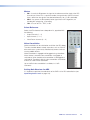
USB Configuration Port (Front Panel)
A front panel configuration port uses an Extron USB A Male to USB Mini B Male
Configuration Cable, 26-654-06 for connection to a PC computer USB port.
The USB 2.0 port uses a mini type-B connector to connect to a host computer for
control. The DMP 128 USB driver must be installed prior to using the port (see Installing
the USB Driver on page 15).
NOTE: The DMP 128 appears as a USB peripheral with bi-directional
communication. The USB connection is used for software operation (see
Windows-based Program Control on page 13), and SIS control (see SIS
Programming and Control on page 129).
Front Panel Indicators
a
ÇÉ
c
d
INPUTS
ACTIVITY
CONFIG
EXP
LAN
1
2
3
4
5
OUTPUTS
6
7
8
9
10
11
12
1
CLIP
CLIP
SIGNAL
SIGNAL
2
3
4
5
6
7
8
DMP 128
DIGITAL MATRIX PROCESSOR
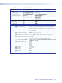
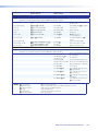
Figure 7. DMP 128 Front Panel
a Power LED — The power indicator blinks during power-up and firmware uploads,
and lights solid when the DMP 128 is operational.
b Activity Indicators — Two green LEDs labeled EXP (Ç) for the expansion audio port
and LAN (É) for the standard Ethernet port
Ç (non-AT models)
Off — The unit is not connected to a second DMP 128.
On — The unit is connected to another DMP 128 and configured as the primary
unit.
Blinking — The unit is connected to another DMP 128 and is currently
configured as the secondary unit.
Ç (AT Models)
Off — Dante device is not responding.
On — The EXP port is connected to a non-AT DMP 128 and configured as the
primary unit.
Blinking — The EXP port is not connected.
É Indicates activity on the corresponding rear panel Ethernet port connection.
c Input Indicators — Stacked red (signal clipping) and green (signal present) LEDs for
inputs 1 through 12 . Each stack represents one input channel.
The green signal LED varies in brightness corresponding to the real-time input or
output signal level (see item d, below). It begins to light at – 60 dBFS increasing
in steps to full intensity as the signal level increases. When the signal level reaches
– 3 dBFS or above, the red clipping LED lights and remains lit as long as the signal
remains above – 3 dBFS. When it falls below that level, the red LED remains lit for 200
milliseconds, after which the display resumes real‑time monitoring of the signal level.
d Output Indicators — Stacked red (signal clipping) and green (signal present) LEDs
for outputs 1 through 8. Each LED stack represents one output channel.
DMP 128 • Installation and Operation
9
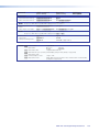
Reset Actuator and LED
A recessed button on the rear panel initiates several reset modes. The rear panel LED
blinks to indicate the reset mode.
4
5
6
7
8
AT
3
1 2 3 4 5 G
11 12 13 14 15 G
6 7 8 9 10 G
16 17 18 19 20 G
1
REMOTE
2
DIGITAL I/O
PHONE
OUTPUTS
Rear Panel
1
2
3
4
RS-232
RESET
Tx Rx G
EXP
LAN
j
Figure 8.
Reset Button and LED
Hardware Reset Modes:
NOTE: The reset modes listed below close all open IP and Telnet connections, and
close all sockets.
With power on, when the reset button is held down, the LED blinks every three seconds.
At the first blink Mode 3 is available, at the second blink Mode 4 is available, and the third
blink indicates Mode 5 is available. The reset modes have separate and distinct functions
outlined below (see DMP 128 Hardware Reset Modes on page 169).
Mode 1 — Firmware reset: Disconnect power to the DMP 128. Press and hold the
reset button while applying power to return the firmware to the version shipped with the
unit from the factory. Event scripting does not start when powered on in this mode. This
allows recovering a unit with incorrect or corrupt firmware.
All user files and settings are maintained. When returning the unit to an earlier firmware
release, some user web pages can work incorrectly.
Mode 3 — Events reset: With power on, press and hold the reset button until the reset
LED blinks once (~3 seconds). Release the reset button, then within one (1) second press
it again to toggle events on or off, depending on the current state.
•
If event logging is currently stopped, following the momentary (<1 sec.) press, the
reset LED flashes twice indicating events logging has begun.
•
If any events are currently running, following the momentary (<1 sec.) press, the reset
LED flashes three times indicating the events logging has stopped.
If the second momentary press does not occur within 1 second, Mode 3 is exited.
Mode 4 — IP Address reset: With power on, press and hold the reset button about
6 seconds until the reset LED blinks twice. Release the reset button, then within one (1)
second, press it again to reset the IP settings.
Mode 4:
•
Enables ARP program capability
•
Sets IP back to factory default IP address (192.168.254.254)
•
Sets subnet back to factory default (255.255.0.0)
•
Sets gateway back to factory default (0.0.0.0)
•
Sets digital I/O port mapping back to factory default
•
Turns DHCP off
•
Turns events off
If a second momentary press does not occur within 1 second, the reset is ignored.
DMP 128 • Installation and Operation
10
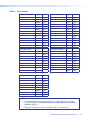
Mode 5 — Factory default reset: With power on, press and hold the reset button
until the reset LED blinks 3 times (~9 seconds). Release then momentarily (<1 second)
press the reset button to return the DMP 128 to factory default conditions. If the second
momentary press does not occur within one (1) second, the reset is exited.
The default (reset) state of the device is:
•
All mix‑points are set to 0 dB gain and muted
•
Input 1 is routed to Output 1
•
Input 2 is routed to Output 2
•
Input 3 is routed to Output 3
•
Input 4 is routed to Output 4
•
Input 5 is routed to Output 5
•
Input 6 is routed to Output 6
•
Input 7 is routed to Output 7
•
Input 8 is routed to Output 8
•
All outputs active (unmuted, 100% volume).
•
No inserted or active DSP processing.
•
All audio inputs are set to 0 dB gain and muted.
•
All preset and group master memory is clear (empty).
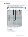
Digital I/O Ports
The four 6-pole 3.5 mm captive screw connector Digital I/O ports provide twenty
configurable digital input or output ports designed to connect to various devices such
as motion detectors, alarms, lights, LEDs, buttons, photo (light) sensors, temperature
sensors, relays (requiring ≥30 mA), and others.
All ports are tied to a common ground (one common ground for each 6-pole connector),
but can be individually configured to operate in one of two modes: digital input or digital
output.
The ports are configured using DSP Configurator. Each port can be configured to monitor
or drive TTL level digital signals (see Digital I/O Ports on page 88).
DMP 128 • Installation and Operation
11
DMP Software
This section describes the control software for the DMP 128, including:
•
Software Control
•
Windows-based Program Control
•
DSP Configurator Program Basics
•
Audio level, Mix‑point, Processing Blocks, and Signal Chains
•
Mic/Line Input Signal Chain Controls
•
Telephone Rx (DMP 128 C P and DMP 128 C P AT only)
•
Line Output Channels
•
Virtual Bus Returns
•
Output Mix Matrix
•
Virtual Send Bus Mix Matrix
•
Expansion Outputs Mix Matrix
•
Group Masters
•
Digital I/O Ports
•
Emulate Mode and Live Mode
•
Presets
•
Protected Configuration
•
DSP Configurator Windows Menus
•
Optimizing Audio Levels
•
Signal Path Building Blocks
Software Control
The DMP 128 can be controlled using the DSP Configurator software, using SIS
commands with hyper terminal or DataViewer (see SIS Programming and Control
on page 129), and accessed using embedded WebPages (see HTML Operation on
page 155).
The DMP 128 has the following connection options:
•
RS-232 — One single stack 3-pole, 3.5 mm captive screw connector is used for
bi‑directional RS-232 (± 5 V) serial control.
See Rear Panel Features and Cabling on page 6, for additional details on
connecting the RS‑232 port.
•
LAN — 10 Mbps, 100 Mbps, half duplex, full duplex connections are supported. Two
LEDs indicate connection and activity status. The device has the following default
Ethernet configurations:
IP Address: 192.168.254.254
Subnet Mask: 255.255.0.0
Default Gateway: 0.0.0.0
DHCP: OFF
See Rear Panel Features and Cabling on page 6, and Connection Options
on page 129 for additional details on connecting the LAN.
•
USB 2.0 — A Mini B-type USB connector located on the front panel provides
high‑speed USB 2.0 connectivity to a host computer, backward compatible to 1.0.
DMP 128 • Software Control
12
Windows-based Program Control
The DSP Configurator Control Program is compatible with Windows XP, Windows Vista,
and Windows 7, and provides remote control of the input gain/attenuation, output volume
output adjustment, and other features.
DSP Configurator can control the DMP 128 by any of the three control ports, RS‑232,
USB, or LAN.
Updates to this program can be downloaded from the Extron website at
www.extron.com.
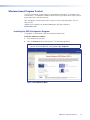
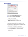
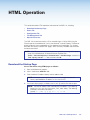
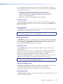
Installing the DSP Configurator Program
The program is contained on the Extron Software Products disk.
Install the software as follows:
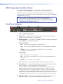
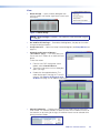
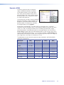
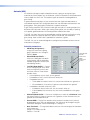
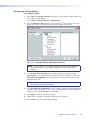
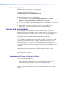
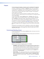
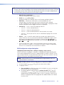
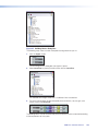
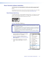
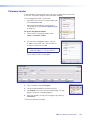
1. Insert the disk into the drive.
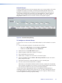
2. Click the Software tab or software icon. The software page opens.
NOTE: If the DVD setup program does not start automatically, run Launch.exe
from the DVD ROM directory using Windows My Computer.
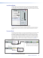
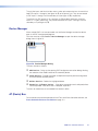
Figure 9. DVD Software Menu
DMP 128 • Software Control
13
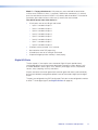
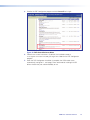
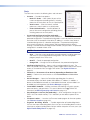
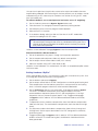
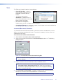
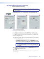
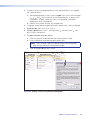
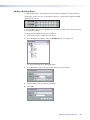
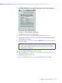
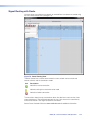
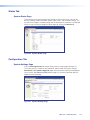
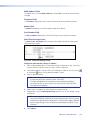
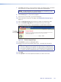
3. Scroll to the DSP Configurator program and click Install to its right.
Figure 10. DVD Control Software Menu
4. Follow the on-screen instructions. By default, the installation creates a
C:\Program Files\Extron\DSP_Configurator folder for the DSP Configurator
program.
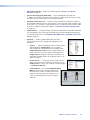
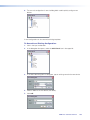
5. When the DSP Configurator installation is complete, the USB Installer starts
automatically (see figure 11, next page). Extron recommends installing the USB
drivers whether they are used immediately or not.
DMP 128 • Software Control
14
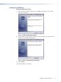
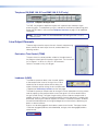
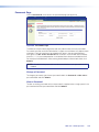
Installing the USB Driver
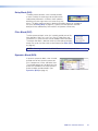
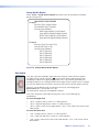
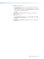
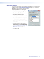
When the USB installer begins:
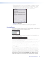
1. When the driver installation dialog opens, click Next to proceed (a status window
tracks the installation).
Figure 11. USB Installer Splash Screen
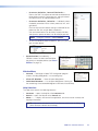
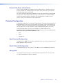
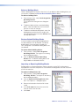
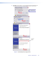
2. The USB driver installer launches. When the installer completes the installation of the
USB drivers, the following dialog opens:
Figure 12. Successful USB Driver Installation
3. Click Finish.
USB driver installation is complete.
DMP 128 • Software Control
15
DSP Configurator Program Basics
Starting the program
NOTE: Extron recommends connection via the Ethernet LAN port for running the
DSP Configurator program.
To run the DSP Configurator Program, click
Start > Programs > Extron Electronics > DSP Configurator > DSP
Configurator.
DSP Configurator starts in Emulate mode (see figure 13, next page). Also see Emulate
Mode and Live Mode on page 89.
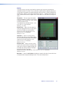
Using the program
In the DSP Configurator Emulate mode, audio parameters can be selected, then
transferred to the DMP 128 by switching to Live mode (while connected to a DMP 128)
and pushing the configuration. Audio settings can also be tailored while connected to the
DMP 128 for real‑time auditioning of the audio output as adjustments are made
(see Emulate Mode and Live Mode on page 89).
The main screen contains controls for the input and output channels, virtual sends and
returns, expansion outputs and inputs, and other information used in the operation of the
DMP 128. There is too much information contained on the main screen to enable viewing
of the entire mix board at one time, so several methods, outlined on the following pages,
are provided to scroll through the screen.
DMP 128 • Software Control
16
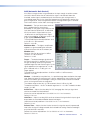
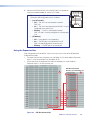
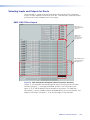
c
a
d
e
b
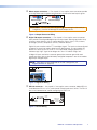
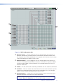
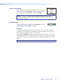
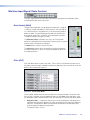
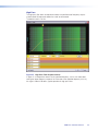
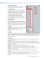
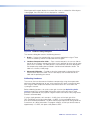
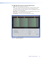
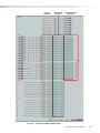
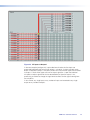
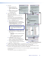
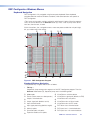
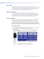
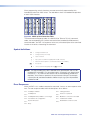
Figure 13. DMP 128 Navigation Aids
a Minimize buttons — Click to toggle the view of a selected section from minimum to
maximum. For example, the Inputs section is maximized with all processor blocks and
the mix‑points shown. Clicking the button in this example shrinks the view to its minimum
screen area allowing items below to fill the screen.
b Maximize buttons — Click to toggle the view of a selected section from maximum to
minimum. For example, the Virtual Returns section is minimized with all processor blocks
and the mix‑points hidden. Clicking the button in this example expands the view to its
maximum screen area.
c Toolbar — All tools and functions not directly available on the main screen are found here.
d Scroll Bar — When the sections are maximized such that the screen area takes up more
space than can be displayed at one time, items are pushed down or up and no longer
appear. Use the scroll bar to bring those items back into view.
e Channel Numbers — <Right-click> the channel number to hide a channel that has no
device connected or is not used in the current configuration.
NOTE: Hidden channels can be shown again using the tools menu and selecting
View > Show All Channels, then unchecking the hidden channels.
DMP 128 • Software Control
17
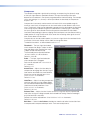
a
b
c
d
e f
g
l
m
h
i
j
k
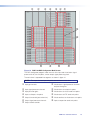
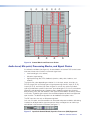
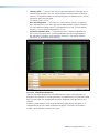
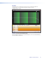
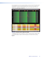
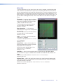
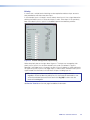
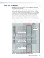
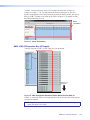
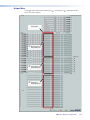
Figure 14. DMP 128 DSP Configurator Main Screen
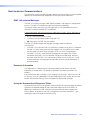
The DSP Configurator program screen consists of an input and virtual return signal
processor chain, the mix-points, and an output signal processing chain.
The main mixer is separated into segments as shown in figure 14.
NOTE: The expansion bus input mix-points are not shown in this view.
a Input gain controls
h Virtual returns signal processor channels
b Input signal processor channels
c Input pre-mixer gains
d Inputs to Outputs mix‑points
e Output trim control (post-mixer trim)
f Output signal processor channels
g Output volume controls
i Virtual returns to output mix‑points
j Virtual returns to virtual sends mix‑points
k Virtual returns to EXP sends mix‑points
l Virtual send bus to virtual returns mix‑points
m Inputs to expansion sends mix‑points
and pre-mixer gains
DMP 128 • Software Control
18
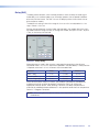
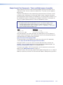
Cut, Copy, or Paste Functions
The user can cut, copy, or paste a processor. These actions can be performed from a
context menu accessed by a right-click on the processor block, using the Edit menu, or
using the standard Windows keystrokes: <Ctrl+X> = cut; <Ctrl+C> = copy; <Ctrl+V> =
paste.
Multiple elements may be acted upon but the blocks copied must be compatible with
the desired paste blocks. A highlighted group of elements can be cut or copied to a
clipboard. The clipboard contents can then be pasted, but succeeds if there is an exact
one-to-one relationship between the clipboard contents and the block or blocks they are
pasted into.
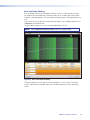
In the following example, the Mic #1 input signal path is copied to Mic #5. First click the
mouse and drag it across the entire signal path. The selected blocks are highlighted in
green. Press <Ctrl+C>, or use the Edit > Copy menu selection to copy the blocks.
As shown below, the starting point for the paste, (the upper/leftmost element), must first
be focused by clicking the mouse on it. Note the green focus outline that appears on the
Mic #4 Gain block. The clipboard elements are pasted using the context menu Paste
command, the Edit>Paste command from the toolbar, or <Ctrl+V>.
NOTE: A cut and copy of elements can be pasted to multiple locations. To copy the
clipboard to an additional location, click on the leftmost block and paste again.
The program warns that all settings in the section pasted to will be overwritten:
DMP 128 • Software Control
19
Click Yes. The entire Mic #4 input path is now identical to the Mic #1 input path including
signal levels, parameters settings, and mute/bypass selections.
Any single processor block is copied, then pasted to a similar processor block in the
same or different input, virtual or output signal path. Mix‑point gains can be copied from
one to another. Input gain, pre‑mixer gain, post-mixer trim, and output volume can only
be copied to like gain blocks. For example, an input gain can be copied to any other
input gain, but cannot be copied to a pre-mixer gain, post-mixer trim, or output volume.
Mix‑point settings can be freely copied between mix‑points. The user is always asked
whether they want to overwrite the existing information. If an attempt is made to copy a
processor block setting to an incompatible block, the user is warned the action cannot be
completed.
Navigation
There are two methods of navigation around the screen:
•
Keyboard
•
Mouse
When a new DSP Configurator file is opened, the upper left element (Output #1 Trim) is
the focus by default.
Keyboard Navigation
All screen elements including mix‑points have the ability to receive focus using the tab and
arrow keys or using the arrow keys following a single click (see Keyboard Navigation on
page 97).
Mouse Navigation
Left-click — Click on a processor block to bring focus to the block, as well as other
elements such as tabs, sliders, check boxes associated with the block. Other left-click
actions follow the Windows standard. In this user guide “click” always refers to a left-click
of the mouse button.
Right-click — A single right-click on a block brings up a context menu specific to that
processor block. Other right-click actions follow the Windows standard.
Double-click — Double-click on a box to open it from either the focused or unfocused
state of an element.
DMP 128 • Software Control
20
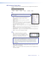
DSP Configurator Toolbar Menus
The DSP Configurator contains the following menu bar, arranged horizontally below the
title bar:
• File
• Edit
• View
• Tools
• Window
• Help
File
NOTE: New, Open, and Recent Files are unavailable in
Live mode.
•
New — Discards the current DSP configuration (after
prompting to save changes) and opens a blank
configuration file.
•
Open — Loads and activates a previously saved DSP
configuration file.
•
Save — Saves all changes to the current DSP configuration
file under the current file name. If the file has not previously
been saved, prompts for a file name.
•
Save As — Saves all changes to the current DSP configuration file under a new file
name.
•
Backup — Recalls and transfers all partial presets plus the current configuration to a
DSP configuration file within the DSP Configurator program.
•
Recent Files — Opens a list of recently opened or saved DSP configuration files.
•
Exit — Closes the DSP Configurator Program.
Edit
•
Cut — Remove all parameters of a selected
processor block or set of selected blocks to the
clipboard. If not followed by a Paste command to a
different block, the parameters are restored.
NOTE: Processor blocks are not removed from the processor stream after a
Cut and a subsequent Paste operation. Only the parameters are moved.
Processor blocks and their parameters can be pasted only into another
block of the same type. For example, the input 1 filter block and all of its
parameters can be copied to the input 2 filter block but not to the input 1
delay block.
•
Copy — Copies all parameters of a selected processor block, gain block, or set of
selected blocks to the clipboard.
•
Paste — Inserts processor blocks and their parameters from the clipboard into the
the location selected.
DMP 128 • Software Control
21
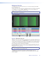
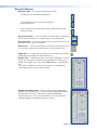
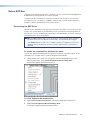
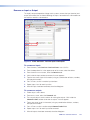
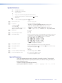
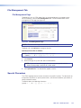
View
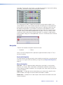
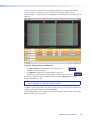
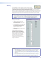
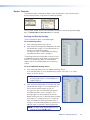
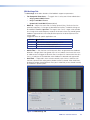
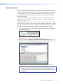
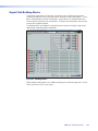
•
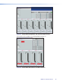
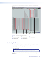
Meter Bridge — Opens a Meters dialog box with
real‑time meters that monitor signal levels at each input
and output.
Figure 15. Meter Bridge
NOTE: Meter Bridge is available in Live mode only while connected using the
LAN port.
•
Re-enable All Dialogs — Re-enables all dialog boxes, the pop-ups that allow
changes to block parameters.
•
Group Controls — Opens the Group Controls dialog box (see Group Masters on
page 82).
•
Network Audio Control Meters
(AT models only) — This menu allows the
user to see the AT meters for an attached Dante
device.
To view the meters:
1. From the main DSP Configurator screen
toolbar, select View>AT Meters.
2. The Browse and Select Device dialog box
opens (see right).
3. Double-click the applicable device. The
meter display opens showing the Tx and Rx
channels. See Viewing AT Channels with
AT Meters on page 125 for addtional information.
•
Show All Channels — Enables channels previously hidden from the main menu
to be viewed. The selection provides an option to either show all hidden channels for
that selection, or by moving to the right, an individual channel can be selected while
leaving the others hidden.
DMP 128 • Software Control
22
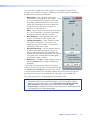
Tools
The Tools menu contains the following items and sub-menu:
•
•
Presets — Provides three options:
•
Mark All Items — Mark (select) all parts of the
current configuration (excluding presets), including
processors and mix‑points to save as a partial preset.
•
Save Preset — Save the currently marked
processors, and mix‑points as a partial preset.
•
Clear Marked Items — Unmark (deselect) all
parts of the current configuration (excluding presets),
including processors and mix‑points.
Protected Configuration (live mode only)—
Allows a user (typically the installer) to save and recall a
protected configuration. The protected configuration is useful to place the parameters
and values (with the exception of the device IP address) in a known state, either as
a troubleshooting tool or as a baseline configuration. The protected configuration,
once saved in the device, is always present and cannot be overwritten without
entering a user-defined Personal Identification Number (PIN) password. The protected
configuration is restored without a PIN.
NOTE: The default PIN is 0000.
•
Save — Save the current configuration (excluding presets), including processors
and mixes as a password protected configuration. The DSP Configurator
program prompts for a PIN to save.
•
Recall — Recall the protected configuration.
•
Change PIN — Change the PIN associated with the protected configuration.
•
Configure Digital I/O — Opens a utility to configure digital I/O ports. The
DMP 128 provides twenty digital I/O ports used to trigger external events from internal
actions, or for external events to trigger DMP actions (see Digital I/O Ports on
page 88).
•
Connect to / Disconnect from Device (depending on Emulate or Live
mode) — Performs the same functions as the Mode Emulate and Mode Live
buttons.
•
Device Manager — Opens the Device Manager dialog box. If a device is
connected, displays the details (model, MAC address, IP address). In addition, a
device can be added or removed, or a selected device cloned, and new folders can
be added to an existing device (see Device Manager on page 81).
•
Issue RESET Command — Initializes and clears the following: mix‑points, presets,
processor blocks, and gain blocks. This reset is identical to the E ZXXX} SIS
command (see SIS Programming and Control on page 129).
•
Save Changes to Device (live mode only) — Saves configuration changes in the
DMP 128 to non-volatile memory. This is advised if you are about to power off the
device.
•
Firmware Loader — Launches the Firmware Loader program for firmware updates
(see Firmware Loader on page 168).
•
Organize Building Blocks — Provides organization of listed building blocks.
You can also import the building blocks file to use your set of building blocks on other
computers or export a building blocks file from another computer to use on yours (see
Signal Path Building Blocks on page 105).
DMP 128 • Software Control
23
•
Configure Groups — Opens the configure groups dialog box (see Group
Masters on page 82).
•
Device Settings (live mode only) — Opens a dialog box to change the
IP address, set administrator and user passwords, change the device name, change
the date and time, and to select the serial port baud rate.
•
Network Audio Control — Launches Dante Controller to facilitate the discovery
of networked audio devices that are compliant with the network audio standard used
by the DMP 128. Discovery is invoked upon launch, and retrieves device name, audio
channels, IP address and the MAC address (see Dante Controller Configuration
on page 118).
•
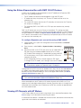
Phone Dialer — The phone dialer utility opens a dialog box that provides telephone
service capability for answering and initiating calls to remote attendees participating
in a conferencing session (see Telephone Rx (DMP 128 C P and DMP 128 C P AT
only) on page 58).
•
Options — Opens a tabbed dialog box that allows
customization of the DSP Configurator appearance and
operation.
•
Colors — Tailor the appearance of the various graphs
and dialog boxes. Appearance uses a selected
color scheme for the complimentary and graph colors.
Complimentary Colors allows custom selection of
colors used with the various graphs and dialog boxes.
Graph colors change the row colors containing the
information and descriptions of the graphs seen in the
processor blocks.
•
Preferences — The startup splash screen contains
options for selection of the devices to connect to, or to
Always ask on startup. That selection can be changed
using Default Device.
•
If Show Meters is set to True, Dynamic Block
Meters can be used to tailor the appearance
of the dynamics meters in order to use the full
meter to show input and gain reduction, or to
show the level based on the output and gain
reduction.
DMP 128 • Software Control
24
•
Processor Defaults, Reset All Defaults —
Returns the DMP 128 processor and level control blocks to
factory default settings. Each processor, and gain/volume/
trim block also has an individual default reset.
•
Processor Defaults, Defaults — Individually selects
the default parameters for the various processor, trim, and
gain blocks.
Each row item contains default settings customized for the
processor, filter, trim, or gain block it represents.
Gain and volume blocks can be initially muted, while filter
and dynamics processor blocks can be initially bypassed.
NOTE: The bypass function is labeled Enable.
•
To view the individual processor defaults, press [
gain, or meter device.
>
•
] to the left of the processor, trim,
Expansion Bus (live mode only) —
Provides a means to select control of either
the primary or secondary device (see Extron
EXP Bus on page 79).
Window Menu
•
Cascade — Rearranges all open DSP Configurator program
screens, including dialog boxes, in a cascading array.
•
Close All Windows — Closes all open dialog boxes.
•
Individual Windows — Lists all open dialog boxes. Clicking on
the name brings the associated dialog box to the front of the desktop.
Help Selection
The Help menu contains the following elements:
•
Contents — opens the Help file at the Contents tab.
•
Search — opens the Help file at the Search tab.
•
About... — displays the name of the application, the current version number, and
copyright information.
NOTE: Help can be activated via the F1 key from any main screen or dialog
(which accesses context sensitive Help).
DMP 128 • Software Control
25
Presets drop-down
This drop-down list displays up to 32 presets. Select a preset to
display and either activate (Recall), abort the selection without
either recalling or deleting (Cancel), or delete it (Delete).
NOTE: An asterisk in the drop-down list indicates a preset exists only in the
DMP 128 and has not been downloaded to DSP Configurator. After recall, the
asterisk is removed.
Mode buttons
Provides selection between Live mode and Emulate mode (see
Emulate Mode and Live Mode on page 89).
Backup
In Live mode (connected to a DMP 128), when presets exist in the DMP 128 that are
not present in DSP Configurator (indicated by an asterisk next to the preset name), the
function halts and prompts the user to run a backup.
Backup (File > Backup) automates the recall of presets from the DMP 128 to a DSP
configuration (.edc) file within DSP Configurator, then displays a prompt to save the file to
the hard drive. Backup is unavailable when the DSP Configurator program is in Emulate
mode.
NOTE: A backup should not be performed during a live event.
DMP 128 • Software Control
26
a
b
c
d
e f
g
l
m
h
i
j
k
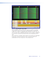
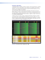
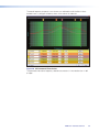
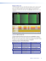
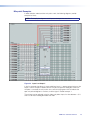
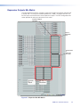
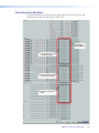
Figure 16. Control Blocks and Processor Chains
Audio level, Mix‑point, Processing Blocks, and Signal Chains
As outlined in red above (see figure 16), all control blocks on the main DSP control screen
have one of three main functions in the overall signal chain:
•
Level control (gain, trim, volume)
•
Mix‑point (signal routing)
•
Signal processing (filter, AEC, feedback, dynamics, delay, duck, loudness, and
automix)
The signal chain varies depending on whether it is in the input, output, virtual bus, or
EXP bus stage. Each of the three types of signal processing channels; Input (a, b, c),
Output (e, f, g), and Virtual (h) shown in figure 16, consist of a series of two basic
types of control blocks specific to that chain: level control (gain a, c, trim e, and volume
control g), and signal processors (frequency filters, feedback suppression, dynamics,
delay, ducking, AEC, AM, and loudness). Both types of control blocks are always present
in the chains. By default, gain controls are unmuted and processor blocks are bypassed
upon insertion. The default configuration can be modified in the options menu.
The EXP input- bus has only an AM processing block.
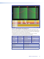
Gain, trim, mix-point, and volume blocks can be muted and processor blocks (after being
inserted) can be bypassed for signal comparison. Mutes and bypasses are shown by a
red indicator in the lower left of the block (see figure 17).
Figure 17. Input Gain Control Muted, Dynamics Processor (AGC) Bypassed
DMP 128 • Software Control
27
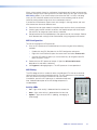
Level Control Blocks
To access a gain, trim or volume control to view a setting, make a change, or observe a
live audio meter (input gain and output volume blocks only), double‑click the gain block
icon (see figure 18). This action opens a dialog box that contains the fader for that control.
Double-click a gain,
trim, or volume control.
A dialog box opens,
containing the full
fader control.
NOTE: In Emulate mode
(the startup mode),
the meter is not operational.
Figure 18. Accessing a Typical Gain Control Dialog Box
Level controls always have a control for setting the signal level and a digital indication of
its current setting. They can also have switches or indicators required for their specific
function.
Processor blocks
Each processor block represents a menu of one or more processors that can be inserted
into the audio stream. For blocks that provide more than one processor, only one can
be selected. Each block can be inserted by a double-click or right-click>Insert
then select the desired processor (see figure 19). Once a block is inserted, the selected
processor displays in the block and the block changes color. Processor blocks default
to bypassed. Bypass is different from mute since the processor passes an unprocessed
signal when in bypass mode. To have them default to “not bypassed”, see Tools on
page 86.
Double-click the
processor block.
-orRight-click the
processor block.
The selected processor is displayed in the
block.
To change processor variables, double-click the
block again to open the processor dialog box.
Click the desired
processor.
Click insert.
Click to select the
desired processor.
Figure 19. Selecting a Processor Block
DMP 128 • Software Control
28
Once a processor is inserted, to view associated parameters that define the selected
processor (such as a frequency curve) or to remove the bypass, double‑click the
processor block. This action opens a new dialog box with parameters for the process (see
figure 20).
Figure 20. Sample Processor Dialog Box
• Click Set Defaults to discard all custom settings and
reload the default parameters.
• Click Bypass to temporarily suspend processing without
removing the processor block. Red indicates the processor is bypassed.
By default, a processor block is bypassed when inserted (the Bypass button in the
processor dialog box is red).
NOTE: Figure 20 is an example of one type of dialog box. Contents and appearance
of each dialog box are unique to the processor type.
The block can be removed from the signal chain by clicking it to bring focus and pressing
<Delete> or by right-clicking and selecting Delete.
Detailed explanations of each signal chain with their processor blocks along with mix‑point
operation follow in the next section.
DMP 128 • Software Control
29
Mic/Line Input Signal Chain Controls
The input signal processor chain allows adjustments to program or microphone audio
material before input to the main mixer.
Gain Control (GAIN)
The gain control provides a single long-throw fader with a range of
– 18 dB to +80 dB, adjustable in 1 dB increments with the fader or
in 0.1 dB increments using direct entry in the level setting readout
below the fader. The peak reading meter holds the peak level for
one second, displaying it numerically in the box below the meter.
The default setting is unity gain (0.0 dB).
The Phantom Power checkbox, turns the +48 VDC phantom
power on (checked) and off (unchecked). Phantom power is typically
used to power a condenser microphone.
The Mute button, silences the mic/line input.
The Polarity button, allows the polarity of wires connected to
the audio connectors (+/tip and – /ring) to be flipped to correct for
miswired connectors.
Filter (FILT)
Each filter block allows a total of five filters. The first filter is inserted from a processor list
that opens when the block is double‑clicked or by selecting it from a context list when the
block is right‑clicked (see figure 21).
Figure 21. Insert Filter Menu
Once inserted, double‑click the processor block to change parameters of the filter. After
the first filter is inserted, up to four additional filters can be added to the filter block using
the dialog box. Select the desired filters from the following list using the drop‑down boxes:
•
High pass filter — A high pass filter passes a band of frequencies extending from a
specified cutoff frequency (greater than zero) up toward the high end of the frequency
spectrum. All frequencies above the specified cutoff frequency are allowed to pass,
while all frequencies below are attenuated.
The default cutoff is 100 Hz.
DMP 128 • Software Control
30
•
Low pass filter — A low pass filter passes a band of frequencies extending from a
specified cutoff frequency (less than infinite) towards the lower end of the frequency
spectrum. All frequencies below the specified frequency are allowed to pass, while all
frequencies above are attenuated.
The default cutoff is 10 kHz.
•
Bass and treble filters — Also known as shelving or tone controls, the separate
bass and treble filters cut or boost gain linearly above or below a specific frequency,
with the end-band shape giving the visual appearance of a shelf. The bass default
frequency is 100 Hz and the treble default is 8 kHz.
•
Parametric equalizer filter — The parametric filter is a frequency equalizer that
offers control of all parameters, including amplitude (the amount of gain/boost or
gain reduction/cut applied), center frequency (frequency), and range of affected
frequencies (Q) around the center frequency.
Figure 22. Filter Block Dialog Box
Open the filter block dialog box to insert additional filters. Select a filter type from the
drop-down filter selection list. All filter parameters are modified using the Filter block dialog
box. Each filter loads with all applicable parameters displayed to the right of each filter
selection.
A balloon number appears at the top of the frequency graph display (see figure 22, a)
corresponding to the row number underneath the graph. The location of the balloon
number is at the frequency selection of that row.
DMP 128 • Software Control
31
Figure 23. Filter Dialog Box, Filters Added
Within the dialog box, a filter is focused when a filter type is inserted, or is focused by
clicking the filter number to the left of the filter selection drop-down list. Note the box
number in row 3 in figure 23 is highlighted in yellow, indicating it is the filter in focus. The
results of the filter in focus (independent of other filters) show in the graph as a dotted line
the same color as its filter row when bypassed. When active (not bypassed), the line is
solid.
When multiple filters are enabled, the graph indicates the focused filter result (independent
of other filters) in the color of the filter row in table. The composite response, the
combined effect of all filters not bypassed, is always displayed in red.
DMP 128 • Software Control
32
Figure 24. Filter Dialog Box, Filter Not Bypassed
Above the graph, each filter has a "handle" (circled in red above) placed directly above
the cutoff or center frequency whose number corresponds to the filter number (outlined in
red). Click a handle or click the table row to bring focus to that filter. Click+hold+drag the
handle horizontally to change the cutoff or center frequency.
The table below shows each filter type with default parameter settings. The table
immediately following shows the possible range for each parameter.
Type
Parameter 1
Parameter 2
High Pass
Frequency
100 Hz
Slope: 6 dB
N/A
Low Pass
10000 Hz
Slope: 6 dB
N/A
Bass
100 Hz
Boost/Cut: 0.0 dB
Slope: 6 dB
Treble
8000 Hz
Boost/Cut: 0.0 dB
Slope: 6 dB
Parametric
1000 Hz
Boost/Cut: 0.0 dB
Q: 1.0
Filter Parameter
Settings Range
Frequency
20 Hz to 20 kHz
Boost/Cut
-24.0 dB to +24.0 dB
Q (Parametric EQ only)
0.707 to 15.000
Slope (HP & LP filters only)
1st Order (6 dB) and 2nd Order (12 dB)
DMP 128 • Software Control
33
High Pass
The high pass filter allows all frequencies above the specified cutoff frequency to pass
unattenuated. All frequencies below the cutoff are attenuated.
The default cutoff is 100 Hz.
Figure 25. High Pass Filter Response Curve
In figure 25, all frequencies lower than the specified frequency, 100 Hz, are attenuated
leaving the upper frequency response flat. Also note at the specified frequency (100 Hz),
the signal is about 3 dB down, typical operation for high pass filters.
DMP 128 • Software Control
34
Low Pass
The low pass filter is the opposite of the high pass filter. All frequencies above the
specified frequency are attenuated allowing lower frequencies to pass.
The default cutoff is 10 kHz.
Figure 26. Low Pass Filter Response Curve
Here, the frequencies higher than the specified frequency, 10 kHz, are attenuated leaving
the lower frequency response flat.
DMP 128 • Software Control
35
Bass and Treble Shelving
Bass and treble shelving can be added to the filter. Known as shelving or tone controls,
the separate bass and treble filters provide the ability to cut or boost gain linearly above
or below a selected frequency, with the end-band shape giving the visual appearance of a
shelf.
If only a bass or only a treble filter is required, either bypass the unneeded control or set it
to Unused in the selection box.
The bass default frequency is 100 Hz and the treble default is 8 kHz.
NOTE:Selecting Bass & Treble Filters inserts two separate filters.
Figure 27. Bass and Treble Shelving
The corner frequency of the controls can be selected to 0.1 Hz accuracy. Two slopes,
6 and 12 dB/octave are available, along with the ability to boost or cut the signal up to
24 dB.
DMP 128 • Software Control
36
Parametric (Equalizer)
The parametric filter is a frequency equalizer that offers control of all parameters, including
amplitude (the amount of gain [boost], or gain reduction [cut] applied), center frequency
(frequency), and range of affected frequencies (Q) around the center frequency. Q is the
center frequency divided by the bandwidth.
Up to five parametric filters can be placed in the filter block at one time, each set to a
different frequency creating a five band parametric equalizer. The control can boost or cut
the center frequency, and by changing the Q value, the range of affected frequencies can
be widened or narrowed around the center frequency. In general, a higher Q value results
in a narrower affected bandwidth.
To demonstrate how Q affects the filter, the following filter block (see figure 28) contains
five parametric filters centered at different frequencies, but with the same Q of 1.0. The
filter in focus (c) has a center frequency of 1000 Hz boosting that frequency +12 dB over
a Q of 1.0. Note the markers on either side of the peak frequency are at about 300 Hz on
the left and 3000 Hz on the right, a bandwidth of 2700 Hz.
Figure 28. Parametric Filter at 1000 Hz, Q: 1.000
DMP 128 • Software Control
37
By increasing the Q to 10.000, the center frequency remains the same. The markers show
the bandwidth of the filter narrowed to between 900 Hz and 1200 Hz, or about 300 Hz
(see figure 29). Using the Q value, parametric filters can be used to notch out a very
narrow, or very wide range of frequencies.
Figure 29. Parametric Filter at 1000 Hz, Q: 10.000
The dialog box above shows the frequency curve for a single active filter. To add its effect
to the overall frequency response, remove the bypass on the other filters by clicking
Bypass.
DMP 128 • Software Control
38
The overall frequency response is now shown as a solid red line with the filter in focus
located in row 3 (see figure 30 below) shown in the color of its table row.
Figure 30. All Parametric Filters Active
The parametric filter allows frequency selection accurate to 0.1 Hz and either 6 or 12 dB
of slope.
DMP 128 • Software Control
39
Acoustic Echo Cancellation (AEC)
The DMP 128 C models provide one acoustic echo canceller processor for each of the
first eight mic/line inputs. A single reference can be selected for each AEC from a list of
the twelve line inputs.
About AEC
Echo occurs when audio from a talker in the far end is received and amplified into the near
end listener’s room, with that sound then being picked up by microphones in the near end
acoustic space and sent back to the far end. The amount of signal sent back to the far
end talker can be substantial, and with the added transmission delay, the result is an echo
effect that seriously compromises communication in a teleconference or videoconference.
The Acoustic Echo Cancellation processor removes the potential echo signal at the near
end mic channel by comparing it to the received signal from the far end, designated as
the “reference,” and then creating an adaptive filter to cancel the potential echo before it is
sent back to the far end.
AEC Setup
Successful operation of the AEC processing block is a function of proper gain structure
and selection of the AEC reference (see Optimizing Audio Levels on page 100). This
section provides an overview of the two elements.
Proper gain structure involves the relationship between the signal at the selected reference
and the signal at the mic input, within the context of proper levels for the reference and
mic inputs independently. The mic input gain setting is naturally optimized for the voice
level of the talker in that room; therefore the amount of signal from the far end that is
picked up by the mic is dependent on how much that far end signal is being amplified in
the near end room and the distance from the mic to the speakers.
The reference signal is the signal received from the far end, which is ultimately sent to a
sound reinforcement system within the near end room. The output of the video codec
might be connected to any of inputs 9 – 12.
In the AEC dialog, a reference can be chosen from any channel in one of three signal
chains:
•
Input Channels
•
Virtual Return Channels
•
Output Channels
Extron recommends using an input channel as the reference. An output channel or a
virtual channel can also be used as a reference; however, doing so adds a little more delay
to the signal being referenced.
Using an output or virtual channel reference allows for the combining of input channels
to a single reference, for example, in a conferencing setup where both a telephone and a
video codec are used. In this case, both the telephone and video codec input channels
can be routed to an output or virtual return, with that output or virtual return then chosen
as the reference.
DMP 128 • Software Control
40
When using an output channel as a reference, the reference point is post volume control;
therefore, changes to the listening volume in the room affects the AEC gain structure (see
AEC Dialog, below). If you have an output channel on the DMP 128 that is not being
used, you can isolate the reference channel from the channel being used for volume
control by routing reference signals to the unused output channel.
If you do want the reference signal to track with changes in listening volume, and want
more control over the actual reference level:
1. Route the far end signal to both the amplifier output and the virtual (unused) output.
2. Create a group master control that contains the amplifier output and virtual output.
Set soft limits for the group master control, as desired.
3. Set optimal level for the amplified output. Set optimal level for virtual output. Relative
levels between both settings will be maintained by using the group master control.
AEC Configuration
To insert and configure an AEC processor:
1. Insert an AEC processor on the desired input channel using one of the following
methods:
•
Double-click the AEC (filter) block in the DSP Configurator workspace.
•
Right-click the AEC block to open the context menu and select Insert AEC.
•
Click the AEC block to select it (or use the arrow keys to navigate to the AEC
block) and press <Enter>.
2. Double-click the AEC processor to open it. Open the Select Reference
drop‑down list and select a reference.
3. Click Bypass to disengage bypass. The AEC processor is now operational.
AEC Dialog
The AEC dialog contains a number of meters and indicator LEDs that are essential for
setting up gain structure and monitoring activity. The AEC reference must be selected
from a list, otherwise the echo canceller will not work. Noise
Cancellation, part of the AEC processor, is selected and adjusted
here. A detailed description of the AEC dialog components is
included below.
Activity LEDs
•
Far – lights when activity is detected from the remote site.
•
Near – lights when activity is detected from the local site.
•
Update – lights when the AEC is updating, converging, or
reconverging.
DMP 128 • Software Control
41
Meters
•
ERL – the ratio in dB between the signal at the reference and the signal at the AEC
channel input. When ERL is a positive number, the signal level at the AEC channel
input is lower than the signal at the selected reference (0 to +15 dB is desirable).
•
ERLE – the amount in dB of potential echo signal that the AEC algorithm, not
including NLP processing, is cancelling.
•
TER – the sum of ERL + ERLE, in dB.
Select Reference
Select the AEC reference from a drop-down list, populated with
the following:
•
Output channels (1 – 8)
•
Input channels (1 – 12)
•
Virtual Return channels (A – H)
Noise Cancellation
Noise cancellation can be switched on or off from the AEC dialog.
The noise canceller detects steady state noise, such as HVAC or
other continuous system noise, and effectively remove it without
causing audible artifacts.
Noise cancellation is engaged or disengaged using a checkbox.
When the box is checked, noise cancellation is engaged, or
switched on. When cleared, noise cancellation is disengaged, or
switched off. The default setting is noise cancellation switched on
and set to 15 dB of noise attenuation.
Up to 20 dB of noise cancellation is available, in 0.1 dB
increments.
Setting Gain Structure for AEC
It is important to optimize the audio levels of the DMP 128 for AEC to be effective (see
Optimizing Audio Levels on page 100).
DMP 128 • Software Control
42
Advanced AEC Controls
Click on the open/collapse icon at the bottom of the AEC dialog to reveal the advanced
AEC controls.
Advanced control functionality is as follows:
Non-linear Processing (NLP) Controls
•
Enable NLP — this box is selected by default. NLP is
necessary for the removal of echo.
•
NLP Presets — click a button to load a set of values
to the three NLP parameters; Max NLP Reduction,
Attack Time, and Release Time.
•
Soft
•
Normal
•
Aggressive
The default parameters (shown at right) match the Normal
preset.
•
Max NLP Reduction – the maximum possible reduction in echo artifacts that can
be applied. The range is 0.0 to 80.0 dB in 0.1 dB increments.
Default is 50.0 dB.
•
Attack Time – the speed in which NLP is applied. The range is 0.0 to 100.0 msec
in 0.1 msec increments.
Default is 6.0 msec.
•
Release Time – the speed in which NLP is released. The range is 1.0 to
3000.0 msec in 0.1 msec increments.
Default is 150.0 msec.
Additional Controls
•
Double Talk Echo Reduction – sets the amount of echo reduction applied
during double-talk. The range is 0.0 to 20.0 dB in 0.1 dB increments.
Default is 15.0 dB.
•
Comfort Noise – sets a comfort noise level in dB to eliminate states of complete
silence, which could be perceived as a failed connection. The range is 0.0 to 40.0 dB
in 0.1 dB increments.
Default is 0.0 dB which turns comfort noise off.
DMP 128 • Software Control
43
Dynamics (DYN)
A dynamics processor alters the dynamic
range, the difference between the loudest
to the quietest portions, of an audio signal.
Each input channel provides two dynamics
processor blocks that, when inserted, provide
one of four types; AGC, Compressor, Limiter,
or a Noise Gate processor.
Once a processor has been inserted, individual
processor parameters can be changed in the
dialog box, accessed by double‑clicking the
processor block. For comparison, the block
can be bypassed by clicking Bypass.
All parameters are displayed in a text box and have a resolution to 0.1 increments.
Parameters can be set by direct entry in the text box to replace existing text, then press
<Enter>, or <Tab>, or clicking to another area. Threshold, gain/attenuation, target,
and ratio parameters have adjustment points on the graph display. Use the mouse to
click+drag the graph point to the desired destination or value. All time values have a
horizontal slider allowing adjustment in 1 ms increments by either a click+drag of the
slider handle, or focusing on the slider, then using left or right arrow keys (the <Page Up>
and <Page Down> keys adjust in increments of 10 ms).
The table below lists each dynamics processor type, parameters, and factory default
settings for the processor.
Parameter
AGC
Compressor
Limiter
Gate
Threshold
-40.0 dB
-30.0 dB
-10.0 dB
-65.0 dB
Max Gain
12.0 dB
500.0 ms
5.0 ms
2.0 ms
1.0 ms
1500.0 ms
100.0 ms
50.0 ms
1000.0 ms
Target
Window
Attack Time
Release Time
-10.0 dB
12.0 dB
Ratio
Hold Time
2.0 :1
0.0 ms
100.0 ms
20.0 :1
50.0 ms
Max. Attenuation
Soft Knee
300.0 ms
25.0 dB
Off
Off
Details of the individual dynamics blocks follow.
DMP 128 • Software Control
44
AGC (Automatic Gain Control)
AGC adjusts the gain level of a signal based on the input strength to achieve a more
consistent volume. Below the set threshold, the signal is not affected. Above the
threshold, weaker signals are boosted up to the maximum gain setting to reach a
user‑defined target level. As the signal level approaches the target level it receives less
gain or no gain at all. Once the signal level reaches the target level all gain is removed.
Click in each field or use the sliders to change the values.
Threshold — The input level where maximum
gain is applied (after the attack time is
exceeded). On the graph at right follow the red
input level from the lower left to -40 dB where
the first red circle is. Signal levels less than
-40 dB remain at their original levels. Signal
levels at or exceeding -40 dB have up to 12 dB
of gain applied (Maximum Gain).
The threshold level can be adjusted from -80.0
to 0.0 dB in 0.1 dB increments.
Default is -40.0 dB.
Maximum Gain — The highest amplification
applied to a signal exceeding the threshold
and up to the lower limit of the window (see
Window below).
Maximum Gain can be set from 0.0 dB to
+60 dB in 0.1 dB increments.
Default is 12.0 dB.
Target — The desired average signal level of
the output when AGC is applied. AGC can vary
the gain according to the input signal level,
specified target level and maximum gain. As the
signal approaches the target level of – 10 dB,
gain is reduced until at – 10 dB, gain is no
longer applied.
The target level can be adjusted from -40 dB to 0.0 dB in 0.1 dB increments.
Default is – 10.0 dB.
Window — Indicated by two yellow lines, is a specified range above and below the target
level. Below the lower line maximum gain is always applied to the signal. When the signal
reaches the window, gain control begins scaling in a linear fashion to achieve smoother
results as the signal reaches the target level.
The window range can be set in 0.1 dB increments from 0.0 dB to 20.0 dB.
The default threshold is – 40 dB. The default target level is – 10.0 dB. The default window
range is 12.0 dB.
Attack Time — Adjusts the time delay for AGC to engage after the input signal level
reaches or exceeds the threshold level.
Attack time can be adjusted from 0.0 to 3000.0 ms in 0.1 ms increments.
Default is 500.0 ms.
Hold Time — Adjusts how long AGC continues to boost the signal after the input signal
drops below the threshold and before release time begins.
Hold time can be adjusted from 0.0 to 3000.0 ms in 0.1 ms increments.
Default is 0.0 ms.
Release Time — Adjusts the time it takes to return the signal to normal (unprocessed)
levels after the signal no longer exceeds the threshold level setting. Release time begins
only after hold time is reached.
Release time can be adjusted from 10.0 to 10000.0 ms in 0.1 ms increments.
Default is 1500.0 ms.
DMP 128 • Software Control
45
Compressor
The compressor regulates signal level by reducing, or compressing, the dynamic range
of the input signal above a specified threshold. The input level to output level ratio
determines the reduction in the dynamic range beyond the threshold setting. For example,
with a ratio setting of 2:1, for every 2 dB of input above the threshold, the compressor
outputs 1 dB.
Compression is commonly used to contain mic levels within an acceptable range for
maximum vocal clarity. A compressor can also make softer sounds louder in one of two
ways. The dynamic range can be reduced by compressing the signal above the threshold
while raising the post‑compressor gain/trim (referred to as "make‑up gain"). Alternately,
the input signal can be increased while the compression ratio above the threshold is
increased correspondingly to prevent clipping. Both techniques have the effect of making
louder portions of a signal softer while at the same time increasing softer signals to raise
them further above the noise floor.
Compression can also be used to protect a system or a signal chain from overload similar
to a limiter. Click in each field or use the sliders to change the values.
The default threshold is -30 dB and default ratio is 2.0:1.
Threshold — The input signal level above
which compression begins (subject to attack
time) and below which compression stops
(subject to hold and release time).
The threshold level can be adjusted from
-80.0 to 0.0 dB in 0.1 dB increments.
Default is -30.0 dB.
Ratio — The input signal level reduction
when compression is engaged.
Ratio can be adjusted from 1.0 to 100.0 in
0.1 increments.
Default is 2.0:1.
Attack Time — Adjusts the time delay for
compression to engage after the input signal
level reaches or exceeds the threshold level.
Attack time can be adjusted from 0.0 to
200.0 ms in 0.1 ms increments.
Default is 5.0 ms.
Hold Time — Adjusts how long compression
continues after the input signal drops below
the threshold and before release time begins.
Hold time can be adjusted from 0.0 to
500.0 ms in 0.1 ms increments.
Default is 100.0 ms.
Release Time — Adjusts the time it takes to return the signal to normal (unprocessed)
levels after the signal no longer exceeds the threshold level setting. Release time begins
only after hold time is reached.
Release time can be adjusted from 10 to 1000.0 ms in 0.1 ms increments.
Default is 100.0 ms.
Soft Knee — Select the Soft Knee checkbox to smooth and soften the transition from
uncompressed to compressed output levels. There are no adjustments.
DMP 128 • Software Control
46
Limiter
The limiter restricts the input signal level by compressing its dynamic range above a
specified threshold. The limiter is most commonly used to prevent clipping, protecting a
system against component or speaker damage. While the limiter is closely related to the
compressor, it applies a much higher compression ratio of ∞:1 above the threshold. The
ratio is fixed and cannot be changed. Click in each field or use the sliders to change the
values.
Threshold — The input signal level above
which limiting begins (subject to attack time)
and below which compression stops (subject
to hold and release time).
Threshold level can be adjusted from – 80.0
to 0.0 dB in 0.1 dB increments.
Default is – 10.0 dB.
Attack Time — Adjusts the time delay for
limiting to engage after the input signal level
reaches or exceeds the threshold level.
Attack time can be adjusted from 0.0 to
200.0 ms in 0.1 ms increments.
Default is 2.0 ms.
Hold Time — Adjusts how long limiting
continues after the input signal drops below
the threshold and before release time begins.
Hold time can be adjusted from 0.0 to
500.0 ms in 0.1 ms increments.
Default is 50.0 ms.
Release Time — Adjusts the time it takes
to return the signal to normal (unprocessed)
levels after the signal no longer exceeds the
threshold level setting. Release time begins
only after hold time is reached.
Release time can be adjusted from 10 to 1000.0 ms in 0.1 ms increments.
Default is 50.0 ms.
Soft Knee — Select the Soft Knee checkbox to smooth and soften the transition from
uncompressed to compressed output levels. There are no adjustments.
DMP 128 • Software Control
47
Noise Gate
The noise gate allows an input signal to pass only when it exceeds a specified threshold
level. Above the threshold level, the signal passes unprocessed; below the threshold the
signal is attenuated at the rate set by the ratio adjustment. The typical setting of the noise
gate threshold is just above the noise level of the environment or source equipment. That
allows signals that are above the noise to pass, and attenuates the noise when there is no
signal to eliminate background noise. Click in each field or use the sliders to change the
values.
Threshold — is the input signal level below
which attenuation (gating) begins (subject to
attack time) and above which gating stops
(subject to hold and release time).
The threshold level can be adjusted from
-80.0 to 0.0 dB in 0.1 dB increments.
Default is -65.0 dB.
Max Attenuation — is the maximum
attenuation of the signal when it drops below
the threshold.
Maximum attenuation can be adjusted from
0.0 to 80.0 dB in 0.1 dB increments.
Default is 25.0 dB.
Ratio — is the input signal level reduction
when gating is engaged.
The ratio can be adjusted from 1.0 to 100.0
in 0.1 increments.
Default is 20.0:1.
Attack Time — adjusts the time delay for
gating to engage after the input signal level
drops below the threshold level.
Attack time can be adjusted from 0.0 to
200.0 ms in 0.1 ms increments.
Default is 1.0 ms.
Hold Time — adjusts how long gating continues after the input signal drops below
the threshold. If the signal is still below the threshold when hold time ends, release time
begins.
Hold time can be adjusted from 0.0 to 500.0 ms in 0.1 ms increments.
Default is 300.0 ms.
Release Time — adjusts the time it takes to return the signal to normal (unprocessed)
levels after the signal is no longer below the threshold level setting. Release time begins
only after hold time is reached.
Release time can be adjusted from 10 to 1000.0 ms in 0.1 ms increments.
Default is 1000.0 ms.
DMP 128 • Software Control
48
Delay (DLY)
The delay processor block, when inserted, provides a means to delay the audio signal.
Audio delay syncs audio to video or can time-align speakers that are placed at different
distances from the listener. The DMP 128 can set delay by either of two criteria: time or
distance (feet or meters).
The default unit setting is time with a range of 0.0 ms to 200.0 ms adjustable in 0.1 ms
steps. Default is 100.0 ms.
Settings are controlled with a vertical slider and indicated in the readout field. Click within
the readout field to change the value, or change the number, then press <Enter>, or press
<Tab>, or click away from the field.
Figure 31. Delay Dialog
Slider adjustments made in feet or meters correspond incrementally to the distance
required to make 1 ms, or 5 ms adjustments (detailed in the table below). If more precision
is required, enter time in 0.1 ms increments into the readout field.
Method
Time
Feet
Meters
Click + drag
1 ms
~1.1 feet
~0.3 m
Focus + arrow
1 ms
~1.1 feet
~0.3 m
Focus + Page Up/Down
5 ms
~5.6 feet
~1.7 m
When distance (feet or meters) is chosen, the conditions (temperature) field becomes
available and can be set either by degrees Fahrenheit or Celsius by clicking the
appropriate selection button. When entering a distance, time delay compensation is
automatically modified based on differences in the speed of sound due to air temperature.
Default is 70 degrees Fahrenheit.
NOTE: When using distance (feet or meters), set a temperature value first, then set
the distance.
DMP 128 • Software Control
49
Ducking
Ducking provides a means to duck, or lower, the level of one or
more input signals when a specified source must take precedence.
The ducking processor block, when inserted, provides a means
to duck one or more mics and program material (ducking targets) when the processor
detects a signal from the ducking source. Ducking lasts for the duration of the interrupting
signal (ducking source) determined by the threshold setting (plus hold and release time)
and restores the original levels of the ducked inputs once the other signal has ceased.
NOTE: Ducking is not functional when an input chain includes active automixing. If
the input to output mix-point is orange, indicating it includes automixing, ducking
will not function for that input. To enable ducking either delete the automix
processor in the signal chain or uncheck Includes Automixing at the
mixpoint.
Ducking is useful when:
•
•
•
Program material needs to be
attenuated in order to more clearly
hear a narrator voice.
One microphone, such as one used
by a master of ceremonies, needs
to have priority over other mics,
program material, or both.
A paging mic needs to attenuate all
other signals.
All ducking processor blocks are
controlled via a common dialog box
that opens when any of the ducking
blocks are selected. All empty ducking
processor blocks have no ducking
source or target settings by default.
When the first ducking source is
inserted (shown at right), no ducking
targets are selected.
Ducker Configuration
Priority
Input #1
Input #2
Input #3
Input #4
Input #5
Input #6
Input #7
Input #8
Input #9
Input #10
Input #11
Input #12
Input #1
Enable Source Mic/Line
Duck:
by (dB):
Input #2
20.0
Input #3
20.0
Input #4
20.0
Input #5
20.0
Input #6
20.0
Input #7
20.0
Input #8
20.0
Input #9
20.0
Input #10
20.0
Input #11
20.0
Input #12
20.0
Vtr Send A
20.0
Vtr Send B
20.0
Vtr Send C
20.0
Vtr Send D
20.0
Vtr Send E
20.0
Vtr Send F
20.0
Vtr Send G
20.0
Vtr Send H
20.0
Settings:
-30.0
dB
1.0
ms
Hold Time
1000.0
ms
Release
1000.0
ms
Threshold
Attack Time
NOTES:
• Signal reduction is not cumulative. Ducking reduces an input by the amount
set in the by (dB): text box next to the input selection even if it is being
ducked by another ducking source (see Ducking and Priority Ducking on
page 53).
• Duck targets do not affect signals routed to expansion outputs 1 through 8.
• Duck targets do affect signals routed to expansion outputs 9 through 16.
DMP 128 • Software Control
50
Ducking Configuration
Ducking is configured in a dialog box that opens when an
active ducking processor block is double-clicked.
a Current Source
Shows the input selected as the ducking source. Ducker
settings affect the input channel shown here. When a
ducker dialog is opened, the current source defaults to
that channel. The current source can also be selected via
the priority readout/source selector (see below).
a
b
c
e
d
b Enable Source Mic/Line checkbox
When checked, ducking is enabled for the current source
and the ducker processor block is lit. When cleared,
ducking is disabled for the current source and the ducker
processor block is unlit.
c Duck: (targets)
Shows all potential input targets. Only inputs checked are
ducked. The current source is not available as a target (a
source cannot duck itself). If the current source has been
designated as a target of another input channel, that input
channel is not available (a target cannot be the source).
d by (dB):
Individual attenuation settings for each duck target in dB. f
The default is 20.0 dB. If additional attenuation of a target
is required, increase this value.
The attenuation range is 80.0 to 0.0 dB in 0.1 dB
increments.
e Priority
Displays the hierarchy of ducking source to duck targets.
Priority levels are displayed in tree fashion. Input channels that are targets being ducked by a source are
shown as indented below the source. Any input channel displayed in the tree is an active link. Click an
input channel to select that channel as the current source. The current source indicator (a) reflects the
selected input channel.
f Settings:
Used to configure the parameter settings for the ducker source. When a ducker block is copied, these
settings are transferred.
Threshold — Sets the input signal level, in dB, the ducking source must exceed before ducking
begins. If ducking does not occur quickly enough to avoid loss of speech or program material from the
ducking source, decrease this setting. If ducking occurs too soon, allowing background noise to trigger
ducking, increase the setting.
The range is -60 to 0 dB in 1 dB increments. Default is -30 dB.
Attack Time — Adjusts the time to duck the targets once the threshold is exceeded.
The range is 0 to 3000 milliseconds in 1 millisecond increments. Default is 1 millisecond.
Hold Time — Determines the time, in milliseconds, after a ducking source signal drops below the
threshold before ducking ceases.
The range is 0 to 10000 milliseconds in 1 millisecond increments. Default is 1000 milliseconds
(1 second).
Release — Determines how long, in milliseconds, after the ducking source level is below the threshold
and the hold time is met, the ducking targets take to restore signal levels.
The range is 10 to 10000 milliseconds in 1 millisecond increments. Default is 1000 milliseconds
(1 second).
DMP 128 • Software Control
51
Priority
In some cases, multiple levels of ducking can be required to enable an input source to
take precedence over all but one other input.
In this example, Inputs 2 through 6 are set to duck when Input #1 has a signal above the
ducking threshold. Input #2 is set to duck inputs 5 and 6. Since Input #1 has previously
been set to duck Input #2, Input #1 is disabled to prevent contradictory priorities.
Figure 32. Ducker Configuration, Input Priority
Notice the priority tree on the right side of figure 32. The inputs are arranged by their
priority status. Input #1 has all other ducked inputs under it, therefore if a signal is
detected, it will trigger Inputs 2 through 6 to duck. If Input #2 detects a signal and there is
no signal on Input #1, Input #2 will trigger inputs 5 and 6 to duck. However if the Input #1
signal exceeds the threshold, it will then duck all inputs including Input #2.
NOTE: Ducking attenuation is not additive. When an input target is ducked,
regardless of how far down the priority line it is, the maximum attenuation is that
set for the individual input and virtual send in the “by (dB):” column near the
center of the dialog box.
See Ducker Tutorials on the next page for additional information.
DMP 128 • Software Control
52
Ducker Tutorials
The examples below are based on different input configurations. Insert a ducker from a
ducker processor block using one of the following methods:
Double-click the block,
then click Ducker
-or-
Right-click the box to open context
menu, then click Insert Ducker
Once inserted, double-click on the ducker block to open the ducker configuration dialog
box. The Enable Mic/Line Source box is checked.
Ducking and Priority Ducking
The first inserted mic ducks all selected targets.
To set a ducking source:
1. Insert a ducking processor on input #1.
2. Open the ducker configuration dialog box and select
the desired duck targets. In this example inputs #2
through 6 are the ducking targets.
Any signal on input #1 that exceeds the ducking
threshold now ducks inputs 2 through 6.
The ducking processor also provides a means to have
an additional input duck other targets using the priority
feature. The second input ducks its selected duck
targets, and can also be ducked by the first ducking
source.
To set an additional ducking source:
1. Insert a ducking processor on the additional ducking source.
In this example input #2 is the second ducking source, with input #1, as shown
above, as the first source.
NOTE: Since it was previously selected as a
ducking target, Input #1 is not available as a
target of input #2.
2. Open the ducking dialog box for the input and select
the desired duck targets. In this example inputs #5
and #6 are the ducking targets of input #2.
Any signal on input #2 that exceeds the ducking
threshold now ducks inputs 5 through 6. The
ducking targets can be changed at any time by
double‑clicking the input #2 ducking processor block.
Since input #2 is a target of input #1, if a signal on
input #1 exceeds the ducking threshold, inputs 2
through 6 are still ducked regardless of whether the
signal on input #2 exceeds its ducking threshold.
NOTE: No input will be ducked more than the
amount set in the by(dB): box.
DMP 128 • Software Control
53
Automix (AM)
An automixer manages multiple microphone sources, gating or varying input gain
automatically. When properly set, the automixer system will improve use and performance
when multiple mics are in use. The two basic types of automixer include gated and
gain-sharing.
A gated automixer attenuates an input channel when the signal level drops below a
user‑defined threshold. DSP Configurator allows the user to divide these automixers into
gating groups. Each gating group is effectively a separate automixer.
A gain sharing automixer sets a maximum room gain and splits this among all open mics,
based on their input levels. While a gain sharing mixer typically has less delay in reacting
to a speaker, gated automixers will normally produce a better noise floor.
The DMP 128 allows the user to choose between a gating automixer and a gain sharing
automixer. When the number of open mics (NOM) is set to zero, the automixer is
gain‑sharing. When a NOM value is provided, the automixer is gated.
The DMP 128 uses an automix dialog box to configure the parameters of each channel
and select an AM group.
Automix parameters:
•
AM Group (Assignment) —
Assigns the channel to a gating
group. Selections are 1 through 8.
Default is None.
•
Show AM Group Details —
Accesses a dialog box that details
current groups and the parameter
member assignments to each (see
the following section).
•
Last Mic Mode On/Off — Prevents
all mics from gating off at the same
time, ensuring there is always one
active mic channel. There are four
possible states:
Gating Threshold
Indicator
Channel Level
(RMS)
Channel Level
Readout
If not enabled on any mic input, all mics gate off.
If enabled on all mics, the last active mic remains on.
• If enabled on one mic:
• The enabled mic remains active if it is active when all other mics gate off, or
• If the enabled mic is not active, it gates on when all other mics gate off.
• If enabled on some but not all mics, then:
• If enabled on the last active mic, this mic remains active, or
• If not enabled on the last active mic, then the first enabled mic in the group
gates on.
Chairman Mode On/Off — One mic or multiple mics can be set to Chairman under
the Gating Priority list. When a chairman mic is gated on, all non-chairman mics are
gated off to the off reduction level.
•
•
•
•
Current NOM — Displays the selection of the maximum number of mics that may
be gated open at any time, per gating group. The setting can be changed using the
AM Groups dialog box. Current NOM range is 1 through 12.
•
Gate Threshold — The signal level below which the mic channel gates off and above
which it gates on.
Range is – 60.0 dB to 0.0 dB.
Default is – 50.0 dB.
DMP 128 • Software Control
54
•
Off Reduction — The channel attenuation when a mic channel gates off.
Range is 0.0 dB to 100.0 dB attenuation (0 to – 100 dB).
Default: 60.0 dB.
•
Attack Time — Sets the time at which gain is applied after a channel gates on.
Range is 0.0 msec to 3000.0 msec in 0.1 msec increments.
Default: 10.0 msec.
•
Hold Time — The time that a mic remains active after the signal drops below a
user‑defined threshold.
Range is 0.0 msec to 10000.0 msec in 0.1 msec increments.
Default: 400.0 msec.
•
Release Time — The time it takes to ramp the signal level to the Off Reduction
value when the mic channel gates off.
Range is 10.0 msec to 10000.0 msec in 0.1 msec increments.
Default is 100.0 msec.
•
Gate Status Indicator and meter — The meter provides real-time sampling of the
selected AM channel with a digital readout of the current level the meter. The indicator
lights when the channel is shut off.
To insert an automix block into a channel:
1. Insert an AM processing block in the desired channel.
Either:
• Right-click the AM block and select Insert
Automixer, or
•
Double-click the AM block and select Automixer.
2. Double-click the inserted AM block to open it (see Automix parameters: on
page 54).
The AM block defaults to Bypass (bypass button red). Click Bypass to toggle the AM
block to active (bypass button gray).
DMP 128 • Software Control
55
Automix Groups
Assigning individual automix channels to groups allows you to see and adjust all channels
assigned to the group on one page. The automix group dialog provides details of all
grouped and ungrouped inputs including the automix settings of each channel or mic.
This provides an overview of all channels in the selected group at a glance. Individual
settings can be changed without leaving the groups dialog. You can also select all
Ungrouped items and see the channels currently unassigned to a group.
Figure 33. Automix Groups Dialog
To Configure an Automix Group:
A channel must first have an active automix block before it can be included in an automix
group.
1. Insert an AM processing block in the desired channel. Either:
•
Right-click the AM block and select Insert Automixer.
•
Double-click the AM block and select Automixer.
2. Double-click the inserted AM block to open it.
3. Select the group number from a range of 1 through 8.
4. Set the parameters for the channel.
5. Repeat steps 1 through 3 for all channels in the automix group.
6. Open any AM block and click Select AM Group Details to open the automix
group configuration page.
7. Set NOM (the maximum number of gated mics) for the selected group.
8. Test the system and make adjustments as needed.
Adjustments can be made to individual automix channels using the rows by opening
each individually, or globally to all channels using the AM group details page. Observe
the Gate Status indicators to verify that channels gate on properly.
The AM Group Details dialog provides details of all grouped and ungrouped inputs
including the automix settings of each channel or mic. This allows viewing of all channels
in the selected group at a glance to provide an overview of the group. Individual settings
can be changed without leaving the groups dialog.
DMP 128 • Software Control
56
Configuring an Automix Channel
Before configuring automix, Extron recommends that you set proper gain staging for the
input mics. This ensures that adequate signal is provided for automix to work properly.
An automix block is inserted for each microphone, and the mic assigned to a group (see
figure 33, Automix Groups Dialog on the previous page). Setting a reasonable NOM, the
maximum number of gated mics) for the microphone group will increase intelligibility by
limiting the number of open mics that are allowed to gate on at once. A NOM of three is
recommended.
In events where a small number of talkers may need priority over other talkers (such as a
presenter at a lectern) chairman mode can be enabled on the priority input channel.
Last mic mode can minimize the frequency of gate changes. This prevents rapid switching
of input mics by, ensuring that a talker is not gated off when their speech is paused.
After the automixer is configured, be certain to set the appropriate mix‑points to include
automixing.
Pre‑mixer Gain (GAIN)
The pre-mixer gain control provides gain or attenuation
after the input processing signal chain. It includes a mono
long-throw fader with a – 100.0 to +12.0 dB gain range,
and a current level setting readout below the fader. Fader
adjustments are in 1 dB increments, while adjustments can
be entered manually to 0.1 dB resolution.
Default is unmuted at unity (0.0 dB) gain.
Selecting the fader handle with the mouse or clicking within
the fader area brings focus to the fader. The input signal level
can be adjusted using any of the following methods:
•
Select and hold the fader handle, then drag it to desired
level in 1.0 dB steps.
•
Select or tab to the fader handle, then use the up/down
arrow to set the desired level in 1 dB steps.
<Page Up> increases and <Page Down> decreases the
level in 5 dB steps.
•
Click in or tab to the level readout field. Type a new value, then press <Enter> or
<Tab> to another area.
DMP 128 • Software Control
Fader Handle
Input
Signal Level
Readout
57
Telephone Rx (DMP 128 C P and DMP 128 C P AT only)
Figure 36. Telephone Rx Signal Path
The DMP 128 provides a telephone interface with separate input and output signal
processing paths. The telephone input (Rx) is identical to the other input processing paths
except the AEC block is not used. See Telephone Interface on page 126 for additional
information.
NOTE: The country code must be entered before connecting the DMP 128 to a
phone system.
Line Output Channels
There are eight mono line output channels. Controls and processing
blocks, identical for each output channel, are described in the
following sections.
Post-mixer Trim Control (TRIM)
The post-mixer trim control provides a fader for fine adjustment of
the program material prior to the output signal chain. The trim control
has a range of – 12 dB to +12 dB in 0.1 dB increments.
Default is unmuted at unity (0.0 dB) gain.
Loudness (LOUD)
The loudness processor block, when inserted, applies
a filter compensation curve to the signal in an inverse
relationship to the output volume control setting; the
higher the output volume setting, the less compensation
is applied (see Calibrating Loudness on the next page).
The loudness processor compensates for changes in human perception to varying volume
levels by applying a filter compensation curve to the signal in an inverse relationship to
the gain control setting. The higher the gain setting, the less loudness compensation is
applied. Generally, as volume is lowered, perception of certain frequencies is progressively
diminished, returning to a more flat response as volume is increased. Loudness will boost
those diminished frequencies to the highest degree at low volume levels, decreasing the
boost as volume increases.
Bypass must be disengaged for the loudness processor to function. The bypass button
is red when engaged (loudness control defeated), and gray when disengaged (loudness
control active).
DMP 128 • Software Control
58
When bypassed, the graph displays the current filter curve as a dotted line. When bypass
is disengaged, the current filter curve is displayed as a solid line.
Figure 34. Loudness Dialog Dialog box
The Loudness dialog box contains the following elements:
1. Graph — Displays the compensation curve currently applied to the signal. These
curves are read-only, and are not adjustable from the graph.
2. Loudness Compensation slider — From a center zero-point, the user can slide to
the left for less loudness compensation (filter curve is reduced), or to the right for more
(filter curve is increased). The slider position is translated into a dB value, displayed in
the compensation readout box contained in the Advanced Calibration section. The
slider has a 48 dB (±24 dB) range.
3. Advanced Calibration — Provides a value that corresponds to the position of the
compensation adjustment slider. The SPL box displays the summed value of the
slider and the preceding trim control.
Calibrating Loudness
The user can fine‑tune the amount of loudness compensation using the compensation
adjustment slider and adjusting “by ear,” or by measuring SPL levels in a particular room,
then using the slider to adjust the loudness filter relative to the SPL of the room and
system gain structure.
Before calibrating loudness, set up the system gain structure (see Optimizing Audio
Levels on page 100). A pre-recorded track of pink noise or pink noise from a signal
generator is preferable for this purpose. Program material can also be used (using familiar
material is recommended).
If using a signal generator, set it to output – 10 dBu, then set the input gain of the
DSP Configurator so the input meter reads – 20 dBFS. If using a recorded source, the
pink noise should be recorded at – 20 dBFS and the player output level setting control set
to maximum, or 0 dB of attenuation. For program material, set the input level to meter at
approximately – 15 dBFS, with peaks safely below 0 dBFS.
DMP 128 • Software Control
59
Unmute the mix‑point from the pink noise source to the output connected to the room
amplifier being calibrated. With the basic gain structure previously set up, loudness can be
calibrated using an SPL meter or by ear. (Loudness can also be set using an SPL meter,
then fine-tuned by ear.)
To calibrate loudness, use a sound pressure level meter set to “C” weighting:
1. Set the Loudness processor to Bypass (Bypass button red).
2. Place the meter in an average (but somewhat prominent) listening location.
3. Generate pink noise, or start the program material playback.
4. Measure the SPL in the room.
5. In the loudness dialog, adjust the slider until the value in the SPL readout box
matches the reading on the SPL meter.
NOTE: Theoretically, calibration can be performed with the output channel
volume and post‑mixer gain level set to any comfortable listening level. But a
relatively loud volume (well above the ambient noise in the room) that can be
easily measured is preferred.
Loudness is now calibrated. Disengage Bypass to hear the compensation.
Alternate method to calibrate loudness:
1. Set up the procedure using steps 1 through 3 of the previous procedure.
2. Set the compensation adjustment slider to its default center position.
3. Set the output channel volume fader to 0 dB (100% volume).
4. Adjust the amplifier until the SPL meter reads 90 dB.
Loudness is now calibrated. This method works if 90 dB is an acceptable amplifier volume
limit for the room.
Setting Loudness “By Ear”
When setting loudness by ear, it is essential the system gain structure be set up first. Sit in
an average (but somewhat prominent) listening location.
1. Set the loudness processor to Bypass.
2. Set the output volume fader in the DSP Configurator to a relatively quiet listening level.
Filter compensation from the loudness processor is most prominent at low listening
levels. Use familiar program material set to the levels described earlier.
3. Set the Calibrate slider to 0, the center point. Disengage the loudness Bypass.
The result is a moderate enhancement to the program material, with more
accentuated bass frequencies (below 500 Hz), and more brightness in the high
frequencies that carry harmonic content (above 7 kHz). Engage and disengage
the Bypass switch in order to “A/B” the difference between loudness off and on,
respectively.
4. To experiment with less loudness compensation, move the loudness compensation
slider to the left (less). For more loudness compensation, move the slider to the right
(more).
5. Any adjustment made to the loudness compensation slider will carry through to all
listening levels. Set the output volume fader in the DSP Configurator to a relatively
loud listening level.
6. Engage and disengage the Bypass switch in order to “A/B” the difference between
loudness off and on. At a loud listening level, the difference should be minimal or
barely perceivable.
DMP 128 • Software Control
60
Delay Block (DLY)
The delay processor block, when inserted, provides
a means to delay the audio signal to compensate for
loudspeaker placement in situations where speakers
delivering the same signal are much farther away than
others. The delay processor block is identical to the delay processor available on
the input (see Delay (DLY) on page 49). Typically the near speakers would be
delayed so that audio delivery time matches the speakers further away.
Filter Block (FILT)
The filter processor block, when first inserted, provides one of four
filter selections: High Pass, Low Pass, Bass & Treble filters and
Parametric EQ. Up to nine filters can be added to each filter block.
The output filter block is identical to the input filter processor block
except that up to nine filters total can be selected (see Filter (FILT)
on page 30).
NOTE: Selecting the Bass & Treble Filter inserts two separate filters.
Dynamics block (DYN)
A dynamics processor block, when inserted,
provides one of four dynamics processors:
AGC, Compressor, Limiter, and Noise Gate.
The available processors are identical to the
processors available on the input dynamics
processor block and described in (see
Dynamics (DYN) on page 44).
DMP 128 • Software Control
61
Volume Control (VOL)
Each output channel volume block provides a mono long‑throw
fader and a volume setting readout (in dB) below the fader. Volume
level is adjustable with the slider or by entering the desired level
directly into the volume setting readout in 0.1 dB increments.
Clicking the fader handle or clicking within the fader area brings
focus to the fader. The input signal level can be adjusted using any
of the following methods:
•
Click and hold the fader handle, then drag it to desired level in
1.0 dB steps.
•
Click or <tab> to the fader handle, then use the
<up> and <down> arrow keys to change the desired level
in 1 dB steps. <Page Up> (increase) and <Page Down>
(decrease) the level in 5 dB steps.
•
Click in or tab to the level readout field. Type a new value, then
press <Enter> or <Tab> to another area.
The default setting is unmuted, at 0 dB attenuation. A peak meter
displays the real‑time audio level from – 60 to 0 dBFS.
Click OK to accept settings and close the dialog box. Click Cancel to ignore changes
and close the dialog box.
The output volume control provides level control for each output. The output control is a
trim control adjustable from – 100.0 to 0 dB. The default setting is unity gain (0.0 dB).
The Polarity button, allows the polarity of the wires connected to the audio connectors
(+/tip and -/ring) to be flipped in order to easily correct for miswired connectors.
The Mute button silences the post-meter audio output. When the audio output is muted,
the mute button lights red, and red indicators in the block turn on.
If the output has been grouped with other inputs or outputs, the group number is
indicated on the right side of this button (see Line Output Channels on page 58).
Telephone Tx (DMP 128 C P and DMP 128 C P AT only)
Figure 35. Telephone Tx Signal Path
The DMP 128 provides a telephone interface with separate input and output signal
processing paths. The telephone output (Tx) is identical to the other output processing
paths. All signals routed to the Telephone Tx are also available on output 8.
See Telephone Interface on page 126 for additional information.
NOTE: The country code must be entered before connecting the DMP 128 to a
phone system (see Telephone Configuration on page 126).
DMP 128 • Software Control
62
Virtual Bus Returns
There are eight mono virtual bus return inputs, fed by the virtual sends. Channel controls
and processing blocks described in the sub-sections that follow are identical for each
virtual bus return channel.
The eight returns are divided into two similar paths. Channels A through D contain a
feedback suppression processing block in each channel. Channels E through H are
identical except there are no feedback processing blocks.
Virtual Bus Returns, A-D
The virtual bus is used when additional processing of an input signal is required. It is also
useful to apply identical filtering, dynamics processing, loudness compensation, or signal
gain/attenuation to multiple inputs.
Feedback Suppressor (FBS)
The Feedback Suppressor (FBS) is used when there is indication of feedback during
live operation. Dynamic filters automatically detect feedback on a live mic channel, and
engage a set of up to 5 fixed and 15 dynamic filters to counteract the frequency peaks at
the detected feedback frequency. Up to 15 separate filters can be employed at any time.
The 15 filters act in a FIFO, or first in, first out rotation. If all 15 filters are employed, when
an additional feedback frequency is detected it overwrites the first detected feedback
frequency and so on.
To avoid a new feedback frequency overwriting a previously detected one, up to five of
the dynamic feedback frequencies can be placed into fixed filters. Once written into the
fixed filters, the feedback frequency can only be overwritten by manually writing a new
frequency to the filter.
The FBS dialog box has three tabs; Settings, Dynamic Filters and
Fixed Filters. Global settings and view options are controlled from the Settings
tab. Dynamic to fixed filter allocations are handled from the Dynamic Filters tab. Filter
parameters can be modified from the Fixed Filters tab.
DMP 128 • Software Control
63
The FBS dialog box provides the following global buttons:
•
Clear All — Clears all dynamic filter settings.
•
Lock — Locks the dynamic filters to current settings, preventing automatic updates.
This temporary mode is useful while testing the system, or during the time when
dynamic filters are being converted to fixed filters. When the FBS dialog box is closed,
lock mode is automatically disengaged.
•
Bypass FBS — Turns off feedback detection when engaged (button is red). Only the
dynamic filters are bypassed. Fixed filters remain active.
•
Set Defaults — Click once to return the FBS to default settings.
Figure 37. Feedback Suppressor
DMP 128 • Software Control
64
FBS Settings Tab
The Settings tab enables selection of the feedback suppressor parameters.
•
•
For Composite View show: — The graph view is set by one of three radio buttons:
•
Only Dynamic FBS Filters
•
Only Fixed FBS Filters
•
Dynamic & Fixed FBS Filters (default)
Mode: Q — Adjusts the notch filter Q used by dynamic filters. Similar to Q on the
parametric equalizers, Q changes the bandwidth of the filter. The default setting can
be modified in Tools > Options. The range is from 5 to 65. Larger values provide
less change to the audio frequency response while lower values may provide greater
feedback suppression but with more possible impact to the tonal response of the
source audio.
Suggested values for specific applications are:
Q Value
Application
7
Voice with considerable feedback potential
30
Voice with less feedback potential
65
Music with minimal feedback potential
•
Attack Time — Sets the time at which dynamic filters are generated after feedback
detection. A longer attack time (greater than 200 ms) reduces the chance that music
or audio content will trigger the dynamic filters to respond. A shorter attack time (less
than 2 ms) reduces the time between when feedback is detected and suppressed.
•
Hold Time — Expressed in hours:minutes:seconds up to 9 hours. Hold time sets
the time a dynamic filter setting persists before the filter is cleared. When hold time is
disabled (checkbox cleared) dynamic filters persist indefinitely unless cleared manually
or the device is power cycled.
Figure 38. FBS Settings Tab
DMP 128 • Software Control
65
FBS Dynamic Filters Tab
This dialog contains the fifteen dynamic filters, with a scroll bar to display filters hidden
due to the dialog box size.
Dynamic filters are cut only notch filters, providing attenuation up to 30 dB at the specified
Q. The default Q is set in the Tools > Options menu, but can be changed on the
settings tab prior to engaging the FBS dynamic filters.
NOTE: Changing the Q setting in the options menu after dynamic filters have been
generated clears all dynamic filters.
a
b
c
Figure 39. FBS Dynamic Filters Tab
Frequency and cut values are read only. Dynamic filters are in auto-detect mode when the
FBS block is active (see figure 39, a; Bypass FBS off). If testing reaches a point where no
further changes are desired, the lock button can be engaged. The lock mode of operation
is temporary, and is intended to be used during setup of the FBS. When the FBS dialog
box is closed, lock mode is automatically disengaged.
If there are specific dynamic filters that you want to assure are not overwritten, press the
Move to Fixed button (see figure 39, b) to write the designated filter settings to the first
available filter in the Fixed Filter tab.
NOTE: When a dynamic filter setting is moved to the fixed filter, it automatically
clears that frequency from the dynamic filter.
The Clear button (see figure 39, c) removes a detected frequency from the
corresponding dynamic filter. A cleared filter reverts to auto-detect mode unless Lock
mode is engaged.
DMP 128 • Software Control
66
FBS Fixed Filters Tab
Fixed filters are notch filters with an adjustable center frequency and Q, and up to 30 dB
of cut. The fixed filters are typically set by converting dynamic filters to fixed, however
adjustments to filter parameters can be manually made from the Fixed Filters tab.
Fixed Filters are inactive and the filter type is set to Unused by default (see rows 4 and 5
in figure 40).
Figure 40. FBS Fixed Filters Tab
No filter parameters are displayed when the filter type is set to Unused. As a filter is
moved to the fixed filter tab from a dynamic filter, the filter becomes active and displays
Notch as the filter type. The parameters copied from the dynamic filter are displayed in
the same line. Once a fixed filter is active, settings can be modified or adjusted as needed.
Fixed filters can also be individually bypassed by clicking Bypass.
FBS Settings Ranges and Fixed Filter Defaults
FBS Parameter
Settings Range
Default Setting
Frequency
20 Hz to 20 kHz
N/A
Q
5.000 to 65.000
30.000
Attack Time
0.0 ms to 1000.0 ms
10.0 ms
Filter Hold Time
0 seconds to 9 hours
00:00:00; Disabled
Fixed Filter Parameter
Settings Range
Default Setting
Frequency
20 Hz to 20 kHz
1000.0 Hz
Q
1.000 to 65.000
30.000
Cut
Up to 30 dB cut
0.0 dB
DMP 128 • Software Control
67
Filter (FILT)
Filter function and interface is identical to the mic/line input channel Filter block except
that only three filters are provided (see Filter (FILT) on page 30).
Dynamics (DYN)
There is one dynamics processor block available on each virtual path. Dynamics function
and interface is identical to the mic/line input channel Dynamics block,
(see Dynamics (DYN) on page 44).
Loudness (LOUD)
There is one loudness processor available on each virtual path. The loudness function and
interface is identical to the Output channel Loudness block (see Loudness (LOUD) on
page 58).
Bypass must be disengaged for the loudness processor to function. The bypass button
is red when engaged (loudness control defeated), and gray when disengaged (loudness
control active).
Delay (DLY)
Audio Delay syncs audio to video or to time-align speakers that are placed at different
distances from the listener. The Delay function and interface is identical to the input
channel delay block (see Delay (DLY) on page 49).
Gain (GAIN)
Each virtual input channel gain block provides a mono long-throw fader with a – 100.0
to +12.0 dB gain range, and a level setting readout below the fader. Fader behavior is
identical to the Pre-mix‑point gain block, described in the mic/line input section
(see Pre‑mixer Gain (GAIN) on page 57). Fader adjustments are in 1 dB increments,
while adjustments can be entered manually to 0.1 dB resolution.
Default is unmuted at unity (0.0 dB) gain.
Virtual Bus Returns, E-H
There are four additional mono virtual bus return inputs. Virtual Bus Returns E through H
are identical to A through D except there are no feedback processors.
As with the virtual bus returns A through D, these returns are used when additional
processing of an input signal is required. It is also useful to apply identical filtering,
dynamics processing, loudness compensation, or signal gain/attenuation to multiple
inputs.
DMP 128 • Software Control
68
Output Mix Matrix
The DSP architecture contains an output mix matrix that connects all inputs to the line
outputs, a virtual send mix matrix that connects all inputs to the virtual outputs, and
an expansion (EXP) output mix matrix that connects the mic/line inputs and virtual bus
returns to the expansion outputs (see figure 41 on the next page).
The output mix matrix sets mix levels from the post processing inputs and post
processing virtual returns, to each line output bus. The mix-point behavior is shown on
page 73.
Each mic/line input and virtual bus return is connected to a mix‑point for each of the eight
line outputs. In general, mix levels are set relative to each other, achieving a desired blend
of input signals at an optimal output level, close to, but not exceeding 0 dBFS at the line
output volume block level meter (while accounting for processing that may occur in the
line output signal chain).
NOTE: Although the virtual Output and return lines, A through H, are shown as
end points on the DSP Configurator screen, they are connected A to A, B to B,
C to C, D to D, E to E, F to F, G to G and H to H. These connections cannot be
changed.
DMP 128 • Software Control
69
Output
Mix Matrix
Virtual Send
Mix Matrix
Expansion Output
Mix Matrix
Outputs
Inputs
1
2
3
4
5
6
7
8
Virtual Returns
1
2
3
4
5
6
7
8
Virtual Send Bus
A
B
C
D
E
F
Expansion Outputs
G
H
1
2
3
4
5
6
7
8
Expansion Outputs
9
10
11
12
13
14
15
16
Expansion Inputs
1-8
1
2
3
4
5
6
7
8
A
B
C
D
E
F
G
H
9 - 16
Figure 41. Overview of DSP 128 Mix-matrix
DMP 128 • Software Control
70
Mix‑point Behavior:
Mix-point color — There are three colors of mix-points:
Teal indicates standard processing (default).
Orange indicates that the signal chain includes an
auto‑mix processor.
Green indicates that all signal processing has been bypassed, post
input gain control.
No mix information — A faint transparent circle (teal, green, or orange) on
the mix‑point indicates that it is muted (contains no mix information).
Mix information — A solid circle indicates that the mix‑point contains mix
information (the mix-point is unmuted).
Mouse-over — The cursor changes to a hand when a mouse‑over occurs
at a mix‑point whether the mix‑point contains mix information or not.
Single-click — A single-click (click) brings focus to (selects) the mix‑point,
indicated by a dark green outline around the circle.
Double-click — A double-click opens the mix‑point dialog box. The focus
outline turns light green to indicate the open dialog box. If the mix‑point is
muted, the mix‑point circle is gray and the Mute button in the dialog box is
red.
If unmuted, the bubble is teal and the mute button in the dialog box is
normal (typically gray for most color schemes).
Multiple open dialog boxes — When multiple mix‑point dialog boxes
are open, the mix‑point for the most recently opened dialog box receives
the light green focus circle, while previously opened dialog boxes
relinquish their focus. Focus can be returned by a click on a previously
opened dialog box, or by double‑clicking a mix‑point.
DMP 128 • Software Control
71
Click a mix‑point to bring focus to that mix‑point. A circle appears around the teal
mix‑point, which remains transparent. Double-click a mix‑point to open a configuration
dialog box with the following components:
•
Mono Fader — Sets the signal level from the
selected input to the output bus. Gain range is -35 dB
to +25 dB. Fader behavior is identical to the input
channel gain block described in the mic/line input
section with the exception that course adjustment
(<Page Up> and <Page Down>) increases or
decreases in 5 dB increments.
•
Mute — Mutes and unmutes the signal to the output
bus. The mix‑point ball is transparent when muted
(Mute button red) and solid when unmuted.
•
No Automixing — When selected, bypasses all
automix channel inputs. The mix-point is teal.
•
Includes Automixing — When selected, includes
the automix channel input. The mix‑point turns
solid orange when the mix-point is unmuted and
transparent orange when muted.
•
•
Mix-point
Input #1
Output #1
25
-35
0.0 dB
No Input Processing — When checked, bypasses
all processing for the preceding input string. This
allows a direct comparison of sound between the
unprocessed signal and fully processed. The mix‑point
turns green when unmuted and transparent green
when muted. Default is cleared.
OK/Cancel — click OK to accept changes and close
the box. Cancel ignores changes and closes the
dialog box.
Mute
No Automixing
Includes Automixing
No Input Processing
Input level is set to 0 dB.
The title above the fader reflects the input and output
channel names for the mix‑point. The example on the right
is the Input #1 to Output #1 mix‑point set to 0.0 dB.
OK
Cancel
The input level text below the mute button indicates the input level setting for the input
gain control or mute status of the selected input signal path, in this example 0 db.
Only when the mix‑point is unmuted does the circle become solid.
NOTE:The No Input Processing and Includes Auto‑mixing buttons
are mutually exclusive. You cannot select both. If you are including an automix
channel in the signal path, when you select No Input Processing, Include
Auto‑mixing clears and does not turn back on even when No Input
Processing is unselected. If you want to continue to have an automixing channel
in the signal path, it must be selected again.
DMP 128 • Software Control
72
Mix-point Examples
In order to better understand how mix‑points work, the following diagrams provide
examples of mixes.
NOTE: To simplify the diagrams not all input and output lines are shown.
Figure 42. Input 1 to Output 1
In the first example (see figure 42) input audio from Input 1 is processed and arrives at the
output 1 matrix mix‑point. Double-click the mix‑point to open the dialog box. When the
mix-point is unmuted, the mix junction turns teal with a light green circle to indicate the
open mix‑point dialog box is the focus, and the signal is routed to output 1.
The mix level can be adjusted using the slider or by direct input of a value between – 35.0
and 25.0 dB into the dialog box below the slider.
DMP 128 • Software Control
73
Figure 43. All Inputs to Output 1
In the next example (see figure 43), input audio from all twelve mic/line inputs are
processed individually and arrive at their output 1 mix‑points. As each mix‑point mute
button is released, its output 1 mix‑point junction turns teal, and the signals are all routed
to Output 1. Since all the signals are now on output signal line 1, open the individual
mix‑points to adjust signal levels for the desired balance. Open the output 1 trim,
processing, or volume to change the signal levels or effects for the signals coming from
the mix-points.
In this manner, any single input, or any number of inputs can be routed to any single
output or any number of outputs.
DMP 128 • Software Control
74
Figure 44. Input 1 to All Outputs
In the example in figure 44, input 1 has been routed to all eight outputs by unmuting
the mix‑point for Input 1 for each output (1 through 8) bus. The example also shows the
mix‑point for output four with input processing bypassed (green) and the mix-point for
output eight with active automix.
DMP 128 • Software Control
75
Virtual Send Bus Mix Matrix
The DSP architecture contains a Virtual Send Bus mix matrix that connects the inputs and
virtual bus return signals to the virtual sends. There is an additional mix matrix to route
EXP input signals to the virtual sends.
The DSP Configurator main screen provides control of the virtual bus mix matrix, used
to set levels from input signals to the virtual sends. Each of the twelve mic/line and eight
virtual return inputs are connected to a mix‑point for virtual bus A through H (and the
EXP inputs). Each mix‑point is muted and set to 0.0 dB (unity gain) by default. In general,
mix levels are set relative to each other, achieving a desired blend of input signals at an
optimal level close to, but not exceeding 0 dBFS at the output volume level meter.
The virtual mix matrix contains a section (see figure 45 below) that allow the virtual
bus returns to be routed back to the virtual bus matrix for further processing using an
additional virtual bus processing block. To prevent feedback loops, a virtual channel is
prevented from being routed back to itself by eliminating the mix‑point that would allow
that to occur.
In situations requiring extra processing, the virtual bus return output is routed back to the
virtual bus send mix matrix, which then routes the signal back to a processing signal chain
other than the one it was routed from.
Virtual Send
Bus Mix Matrix
a Virtual Send Bus Mix-points
(from Mic/Line Inputs)
b Virtual Send Bus Mix-points
(from Virtual Bus Returns)
c EXP Inputs to Virtual Bus
Sends
Figure 45. Virtual Bus Mix Matrix (EXP inputs 9-16 not shown)
DMP 128 • Software Control
76
In the example in figure 46 below, input 1 is sent to the virtual send bus by muting all
eight signals on the Input 1 output mix‑points and unmuting virtual send bus output 1.
The virtual bus now serves as additional signal processing for the input. The signal routes
from virtual send A through the virtual bus A signal chain before it is sent to the virtual bus
return mix‑point and finally to output 1.
This configuration is useful when more than one input requires identical processing.
For example if all inputs were normalized but required a uniform gain to bring them up
to adequate output levels, rather than changing each pre-mix gain control by a similar
amount, all twelve inputs can be routed to a virtual bus (in this case virtual bus A). Then,
using the virtual bus A return gain control, a single adjustment can apply the same gain to
all twelve inputs before sending the signal to the desired output.
In other cases, when multiple mic inputs are mixed with program material, only the
program material might require loudness contouring. So the mics are routed directly to the
output but the program material input is routed to the virtual bus return where loudness
contouring is applied. The program material is then routed to the same output as the
mics.
Figure 46. Input 1 to Virtual Bus A
DMP 128 • Software Control
77
Expansion Outputs Mix Matrix
The DSP architecture contains a third mix matrix that supports connection and control of
a second DMP 128 using the included shielded CAT 6 cable. The output connects the
mic/line inputs and virtual returns to the Expansion Outputs. The DSP Configurator main
screen provides all necessary control of the mix matrix.
Expansion Outputs
Mix Matrix
Inputs to
EXP Sends
(1-8)
Virtual Returns
to
EXP Sends
(9-16 only)
Exp Inputs
to
Outputs
EXP Inputs
to
Virtual Sends
Figure 47. Expansion Bus Mix Matrix
DMP 128 • Software Control
78
Extron EXP Bus
Using the Extron Expansion port (EXP), two DMP 128 units can be connected together for
bi-directional communication of 16 channels of audio.
The expansion bus mix matrix can route any or all of the mic/line inputs to any or all of
the expansion outs (1 through 8). In addtion, there are eight channels (expansion outs 9
through 16) directly connected to the virtual bus returns.
Connecting the EXP Ports
Minimal setup is required for EXP port communications. One DMP 128 must be set as the
Primary Unit, and the other as the Secondary Unit to synchronize the sampling clocks of
the two units. This has no bearing on how audio is transported from unit to unit, making it
unimportant which unit is set to primary.
NOTE: You can connect a DMP 128 AT to a non-AT unit by the EXP ports, however
be aware that the AT unit defaults to the primary unit and cannot be changed.
You cannot connect a DMP 128 AT model to another AT model by the EXP ports
because there is no option to set one as primary and the other as secondary as
required.
To enable the expansion bus between two units:
The EXP bus requires one device be configured as the primary unit and the other as the
secondary unit. The tools menu is used to configure the connection.
1. Power on both units. Open DSP Configurator and connect Live to the first unit.
From the main menu, select Tools>Expansion Bus>Primary Unit.
A checkmark appears beside the active unit.
Figure 48. Expansion Bus Unit Selection
2. Select Tools>Connect to Device and connect Live to the second unit.
3. Select Tools>Expansion Bus>Secondary Unit.
A checkmark appears beside Secondary Unit.
DMP 128 • Software Control
79
4. Connect the EXP port of one unit to the EXP port of a second unit
using the included shielded (or similar) CAT 6 cable.
100-240 ~ 0.6A
MIC/LINE INPUTS
MIC
+48 V
1
5
50/60 HZ
100-240 ~ 0.6A
2
3
4
6
7
8
1
5
2
6
3
7
4
8
9
11
DMP 128 C AT
10
O
U
T
P
U
T
S
12
1
2
3
4
5
6
7
8
DIGITAL I/O
1 2 3 4
5
6 7 8
11 12 13 14 15
9 10
16 17 18 19 20
NOTE: The front panel EXP LED indicates device to device
connection and configuration status as follows:
• (non-AT models)
MIC/LINE INPUTS
MIC
+48 V
1
2
3
4
5
6
7
8
1
5
2
3
4
9
DMP 128 C
10
1
O
U
T
P
U
T
S
2
3
6
7
8
11
12
5
6
7
8
2
3
EXP
LAN
4
RESET
Tx Rx
DIGITAL I/O
4
• Off — The unit is not connected to a second
DMP 128.
1
RS-232
1 2 3 4
5
6 7 8
9 10
EXP
11 12 13 14 15
16 17 18 19 20
50/60 HZ
RS-232
LAN
RESET
Tx Rx
• On — The unit is connected to another DMP 128 and
configured as the primary unit.
• Blinking — The unit is connected to another
DMP 128 and is currently configured as the secondary
unit.
• (AT Models)
• Off — Dante device is not responding.
• On — The EXP port is connected to a non-AT
DMP 128 and configured as the primary unit.
• Blinking — The EXP port is not connected.
Using the Expansion Bus
After configuration and connection, the two units have 16x16 channels of bi-directional
audio communication.
•
The expansion bus from the primary unit (see figure 49, a) sends audio to Expansion
inputs 1–16 of the secondary unit (see figure 49, b).
•
At the same time, the expansion bus from the secondary unit sends audio to
Expansion inputs 1–16 of the primary unit.
1
EXP Bus Connection
Primary (1) to Secondary (2)
2
1B
0
1
2A
2
2B
3
4
5
1A
6
Figure 49. EXP Bus Connections
DMP 128 • Software Control
80
The mic/line inputs and the virtual bus returns make up the expansion bus mix matrix that
feed EXP outputs 1 through 8 (see figure 49, Ä) of the primary unit. They are connected
to EXP inputs 1 through 8 of the secondary unit (see figure 49, Å), respectively.
The primary unit EXP outputs 9–16 (see figure 49, Ç) are direct feeds from virtual bus
returns A – H (post processing). They are connected to EXP inputs 9 through 16 of the
secondary unit (see figure 49, É)
Device Manager
When multiple DMP 128s are connected, use the Device Manager to select the device
open in the DSP Configurator dialog box.
From the menu bar, select Tools > Device Manager to open the device manager
dialog shown in figure 50.
abc d
Figure 50. Device Manager Dialog
The icons function as follows:
a Add
Device – Brings up the opening DSP Configurator connection dialog allowing
the selection of the model number of the secondary device.
b Clone
Device – Provides the option to duplicate the primary device configuration
to the connected secondary device.
c Delete
d Expand
Device – Deletes the highlighted device
or Collapse Device – If the device connection tree is collapsed, allows
it to be expanded. If the device tree is collapsed, expands it.
The icons for the devices are unavailable if the device is offline.
AT (Dante) Bus
For connection and software operation of the AT bus and Dante Controller software, see
Dante Controller Software Installation on page 113.
DMP 128 • Software Control
81
Group Masters
There are 32 Group Masters that can each be configured to simultaneously control up
to 16 group members. Group masters are configured in DSP Configurator and saved in
the device. Working in emulate mode, group masters are saved in a configuration file and
pushed to the device upon connection.
A group master can either be a gain control or a mute control. Only one control type
can be selected as group members for control by a group master. For example, a group
master can be configured to control post-matrix gain levels, but not post-matrix gains plus
input gain block. A group member can, however, be controlled by multiple group masters.
It is recommended this feature be used cautiously, as “overlapping” membership can
quickly become unmanageable.
Group master gain controls can send specific values, such as those sent by a fader
control. Group master gain can also be set by increment and decrement (see Tools on
page 86).
Group Members
Once a group has been created, the group members — the individual controls that
comprise the group — update to indicate they are now part of a group. Group members
can be controlled individually, allowing for relative levels between members to be
fine‑tuned. Group member levels can also be set by a preset recall.
Grouped Controls
Grouping is convenient when multiple controls require muting at the same time or when
multiple signal levels need to be increased or decreased simultaneously. For example, in
a system with several audio outputs dedicated to a single room, the operator can want all
outputs to change at the same rate and at the same time. The output 1 through 4 volume
controls are grouped into a master so that one group volume control, controls the volume
throughout the room.
For further flexibility, individual volume controls in the group are set for an output level
based on its use. When the group fader moves, all four output control faders move in
tandem while retaining their levels relative to each other.
Grouped faders move together at relative levels to the top or bottom of their travel (see
figure 51, next page). If one fader reaches the limit of its travel first, it retains that position
while the other faders continue to travel. When the grouped faders travel in the reverse
direction, the fader that was at its limit reverts to its position relative to the other faders.
NOTE: If a block was previously muted when the group mute is activated, that block
remains muted when the group mute is released.
TIP: When including a control in multiple groups, do so with care. Overlapping
group membership can quickly become unmanageable. Use presets to set
individual faders to known levels.
DMP 128 • Software Control
82
Figure 51. Sample Gain Group Master and Associated Gain Controls
Mute controls within the blocks can also be grouped (see figure 52).
Figure 52. Sample Mute Group Master and Muted Outputs
DMP 128 • Software Control
83
Configuring a Group Master
To configure a group:
1. Click Tools > Configure Groups (see figure 52 on the previous page) to open the
Configure Groups dialog.
or click View > Group Controls > Add a Group.
2. Click the Select Group drop-down list (see figure 53). The list defaults to the first
empty group. Select an empty group, or an existing group to overwrite.
Figure 53. Configure Groups, Add Group Dialog Box
NOTE: <empty> groups have no group members assigned. Numbered groups
(such as <Group #1>) have controls assigned that may be overwritten if
selected.
3. In the Select Control Type panel, expand the tree for the type of control,
Gain or Mute, then select the desired control type. When a selection is made, the
Available Group Members section populates with all possible members for the
selected control type.
NOTE: Potential group members in step 4 that are already assigned to a
different group are displayed in blue.
4. In the Available Group Members section, click the checkbox to make appropriate
selections. When a plus sign (+) exists, click to expand the tree and select individual
controls. Up to 16 group members can be added.
5. Click Apply to create or configure the group.
6. Repeat steps 2 through 5 to create or configure up to 32 groups.
7. Click Close to exit the configure groups dialog.
DMP 128 • Software Control
84
Deleting a Group Master
To delete a group:
1. Click Tools > Configure Groups (see figure 54) to open the configure groups
dialog box
or click View > Group Controls and then click Add a Group.
2. In the Select Group drop-down list, click a numbered group (such as Group #1)
to select it.
3. Click Delete Current Group in the lower left area.
4. Click Yes in the Confirm Deletion dialog box.
Viewing and Using a Group Master
Click View > Group Controls to open the group controls dialog box (see figure 54).
The group controls dialog contains two menu items:
•
Add a Group allows you to add additional groups.
•
Tools enable you to perform various functions from the group controls dialog box.
In addition, once groups are created, a single mute button or a group fader plus the
current setting readout and any soft limits that are set are visible.
Figure 54. Group Controls Dialog Box
The group fader controls function as follows:
•
Slide a group fader up and down to adjust all gain controls in the group.
•
Click and drag a soft limit ( ) to set the ceiling and floor for the group.
NOTE: Soft limits cannot be dragged beyond the current setting of the group
fader.
Add a Group
To launch the configure groups dialog box from group controls, click Add a Group. When
a new group is added and the Add New Group dialog is closed, the group controls dialog
box refreshes to display the added control.
NOTE: If a block is muted, that block remains muted when the group mute is
released.
DMP 128 • Software Control
85
Tools
The Tools menu (see right) contains these selections:
•
Clear All Groups — clears all
group members and group master
parameters. Soft limits are also
cleared.
•
Increment/Decrement
Simulator — allows the user to
test increment/decrement values (see
below for more information)
•
Refresh All Group Data —
Updates group members and group master parameters.
•
Group Details Report — generates a report, listing all group masters and membership
(see Group Details Report on page 87).
Increment/Decrement Simulator
The Increment/Decrement Simulator provides a control for increment and decrement, with the
ability to set increment and decrement values. The control is temporary, since the value is not
remembered in the device.
To use the Increment/Decrement Simulator:
1. Select Tools > Increment/Decrement Simulator.
2. Select the group to be controlled from the Select Group drop-down list. The following
dialog box opens:
Figure 55. Increment/Decrement Simulator Dialog Box
NOTE:The Number of Group Members: readout indicates the number of
controls affected.
3. Enter an increment value and a decrement value. The default value is 1.
NOTE: The size of the increment can be changed by typing a value in the
Increment Value or Decrement Value field. Values can be as large as
the maximum range of the control or as fine as 0.1 dB. For groups controlling
mute, 1 is the only valid value.
4. Click Increment and Decrement as needed. The group master control increases or
decreases by the set value to the top or bottom of its soft limit range.
NOTE: When set, soft limits cannot be exceeded.
DMP 128 • Software Control
86
Group Details Report
Select Tools > Group Details Report to create a text file that details all created
groups (see figure 56).
GROUP DETAILS REPORT
Group #1
Processor Type: Output Volume
Current Mute status: Unmuted
Current Group Members:
Main Amp (Output#1) Left Channel
Stage Mixer (Output#2) Right Channel
House Video (Output#3) Left Channel
Prgm Record (Output#4) Right Channel
Group #2
Processor Type: Pre-mixer Trim
Current Gain value: 2 dB
Current Group Members:
Mic #1 (Input#1)
Mic #2 (Input#2)
Mic #3 (Input#3)
Mic #4 (Input#4)
Mic #5 (Input#5)
Mic #6 (Input#6)
Figure 56. Sample Group Details Report
Soft Limits
Each gain type control provides upper and lower soft limits used to limit the range of
the group master control. Soft limits ( ), shown at left, prevent group controls from
exceeding an upper limit or going below a lower limit. They are easily adjustable and
provide the ability to set a ceiling and floor for the group. When a group master is created,
the soft limits default to the hard limits (maximum and minimum) of that group of controls.
Soft limits can be defined using the mouse by clicking on, then dragging the
Soft Limit icon. The resolution is 0.1 dB.
For more precise setting use the keyboard as follows:
Click within the group master fader to bring focus, then use the following key
combinations:
To move the upper limit:
•
<Shift + Up/down arrow> moves in 0.1 dB increments.
•
<Shift + Page Up/Page Down> moves in 10 dB increments.
•
<Shift + Home> moves limit to upper default. <Shift + End> moves limit to the current
fader position.
To move the lower limit:
•
<Ctrl + Up/down arrow> moves in 0.1 dB increments.
•
<Ctrl + Page Up/Page Down> moves in 10 dB increments.
•
<Ctrl + Home> moves limit to the current fader position. <Ctrl + End> moves limit to
lower default.
DMP 128 • Software Control
87
Digital I/O Ports
The DMP 128 provides twenty digital I/O ports that can trigger external events from
DMP 128 actions, or allow external events to trigger DMP 128 actions. DSP Configurator
provides pre-configured scripts with a fixed set of common trigger or event combinations.
When selected, the script is compiled and placed onto the File Management system
of the device. For more advanced or custom scripts, contact an Extron Electronics
Applications Engineer.
When there are no scripts active, the digital I/O ports default to DI (digital input) and
inactive (‘Logic Hi’ ≈ +5 VDC). The DI detects a Logic Hi as +5 VDC and Logic Low
(active) as less than +1 VDC.
A DO (digital output) sends a Logic Lo as less than +1 VDC and a Logic Hi as +5 VDC.
For every script that involves a DO, two versions are available to provide either a Logic Hi
or a Logic Lo response to any action. The alternate script is designated as “Reverse DO”.
To build a script and place it into the DMP 128 File Management system:
1. From the main menu, click Tools>Configure Digital I/O>Build Digital
I/O Configuration.
A dialog box opens with a list of pre-configured scripts.
2. Select a script from the Select a Digital I/O Configuration section. The
Event Description panel describes the script and how the digital I/O ports act
while the script is running. Highlight the desired script, then click OK.
A dialog box opens, verifying the file has successfully uploaded to the device.
NOTE: When performing this procedure in Emulate mode, the connection
dialog appears between step 3 and step 4. The DSP Configurator connects
and then disconnects during the procedure, returning to Emulate mode when
completed.
DMP 128 • Software Control
88
Reinitialize Digital I/O
Should the script stop running for any reason, select
Tools > Configure DigitalI/O > Reinitialize Digital I/O.
This option is only available in live mode.
To remove a digital I/O script from the DMP 128:
Only one digital I/O configuration can be active at a time. If the I/O activity requires
modification, remove the current configuration by:
1. From the main menu, select Tools>Configure Digital I/O > Remove
Digital I/O Configuration from the Device and click OK.
2. If the DSP Configurator is connected to a device, the I/O configuration is removed. If it
is not connected, a connection dialog box appears.
3. Make certain the connection information is correct, then click OK. The I/O
configuration script is removed and a confirmation dialog box appears.
Emulate Mode and Live Mode
DSP Configurator has two operational modes, Live and Emulate. In live mode, the
program has established a connection and is synced with the DMP 128. Changes affect
the device in real-time and changes in the current state of the device are reflected in
DSP Configurator. In contrast, emulate mode allows the user to work offline, creating or
editing configurations that do not immediately affect DMP 128 operation.
DSP Configurator always starts in Emulate mode. In Emulate mode, all functions of
DSP Configurator are available without connecting to the DMP 128. The user can build
a configuration from the blank screen, or open an existing file that contains the last
configuration displayed plus saved presets. Settings and adjustments are saved to
a configuration file on the PC. When the saved file is opened in DSP Configurator, all
settings are restored as the current configuration (emulated if in Emulate mode or live if in
Live mode).
Live mode can be entered at any time after program launch, either with a blank
configuration, after creating a configuration, or after loading a previously saved
configuration file.
In emulate mode, the current state is titled Current Emulation. In live mode, the current
state is titled, Current State.
Synchronizing: Pull from or Push to the Device
When switching to live mode, either:
•
Pull data from the device and update the program configuration. This
option downloads device settings from the DMP 128 and synchronizes it with
DSP Configurator overwriting the current DSP Configurator settings, or
•
Push data from DSP Configurator to the device, overwriting settings in the DMP 128.
Live mode is also used to tailor audio settings in real time while listening to the audio
output.
DMP 128 • Software Control
89
Selecting Live Mode and Pushing or Pulling Data
To switch from Emulate to Live mode:
1. Select the desired connection to the DMP 128 and make the proper connections.
NOTE: Extron recommends connection via the Ethernet LAN port when using
DSP Configurator.
2. Click Live (see figure 57, b). The communication type selection dialog opens.
2
3
3
4a
3
Extron USB device
5a
5b
or
6a
or
4b
4c
5c
6b
Figure 57. Selecting Live Mode
3. To select the connection method, click:
•
TCP/IP (for connection of the LAN port (preferred) — proceed to step 4
•
RS-232 (for connection of the rear panel RS-232 port — proceed to step 5
•
USB (for connection of the front panel configuration port — proceed to step 6
4. If TCP/IP is selected in step 3:
a. Observe the IP address field in the IP connection dialog box. The field displays
the last IP address entered.
• If the IP Address field is correct, proceed to step 4b
•
If the address is not correct, either click in the IP Address field and
enter the correct IP address or click ( ) to open a drop-down list and select
from among recently used addresses. Proceed to step 4b
NOTE: If the local system administrators have not changed the value,
the factory‑specified default, 192.168.254.254, is the correct value
for this field.
b. If the device is password protected, click in the Password field and enter the
appropriate administrator password
c. Click OK
The Synchronize with Device dialog box (see figure 58 on page 92) opens.
Proceed to step 7.
DMP 128 • Software Control
90
5. If RS-232 is selected in step 3:
a. Click the Com Port drop-down list and select the port connected to the rear
panel RS-232 port.
b. Check the baud rate displayed in the port selection dialog box. If the baud rate
does not match the device rate, click the Baud Rate drop-down list and select
the desired baud rate. The default is 38400.
c. Click OK.
The Synchronize with Device dialog box (figure 58 on next page) opens.
Proceed to step 7.
6. If USB is selected in step 3:
a. Click the USB Device drop-down list and select DMP 128 (or Extron USB
device, if DMP 128 is not available),
b. Click OK.
The Synchronize with Device dialog box (see figure 58 on next page) opens.
Proceed to step 7.
DMP 128 • Software Control
91
7. Click either:
a. Pull to configure DSP
Configurator to match the
device — proceed to step 9
-orb. Push to configure the device
to match DSP Configurator
— proceed to step 8
7a
8. To push all of the gain and
processor block adjustments
(configuration), and all presets to the DMP 128,
proceed to step 9.
-or7b
8
9
9
To tailor the push (push only the configuration,
only the presets, or the configuration and selected
presets), click Advanced and proceed to step 8a.
8d
8a
8b
a. Select the Custom radio button.
b. Select the desired checkbox or checkboxes;
Push Configuration and/or Push Presets.
If Push Configuration is the only box
checked, click OK and proceed to step 9.
8c
8d
NOTE: Push Configuration includes
all mix‑point, gain and processor block
settings. It does not include partial
presets.
c. If Push Presets was selected in step 8b, click
All to select all presets or Selected to choose
specific presets.
•
If Selected is clicked, click OK and proceed
to step 8d.
•
If All is clicked (equivalent to a standard
push), click OK and proceed to step 9.
8e
8f
d. If Selected is clicked in step 8c, the
Synchronize with Device dialog box (7b)
reopens. Click OK. The presets dialog box opens.
e. Select the desired partial presets to push by
clicking the appropriate checkbox or checkboxes.
f. Click OK. — Proceed to step 10.
10
Figure 58. Selecting Live Mode (Continued)
9. Click OK. The DSP Configurator program is connected live to the device and the processors and
presets are pushed or pulled as selected, completing the selection of Live mode.
10. If changes are made to the DSP parameters (including mix‑point, gain or processor blocks) since the
last file save, DSP Configurator prompts to save the file. Click Yes or No.
If a password is required and not entered or if an incorrect password is entered, the program prompts
for the password.
The configuration and presets are uploaded to the DMP 128.
DMP 128 • Software Control
92
Presets
Presets recall a group of frequently used settings. Presets created by DSP Configurator
can contain all elements (gain blocks, processor blocks, and mix‑points) or a portion of
the elements available within the program. In Emulate mode, up to 32 partial presets
can be created, then uploaded as a set and stored to the device or stored to disk as a
configuration file. In Live mode, presets can be created one at a time from the current
state. They can be saved to a chosen preset number in the device, with the option to
name or rename, or save to disk.
When recalled, a preset overwrites only elements contained in the preset. Presets are
useful when settings for a particular room or only certain elements of a configuration need
to be changed regularly.
Presets can be created in Live or Emulate modes. In Emulate mode, presets are
created, saved to a file, then pushed to the DMP 128 when connecting in Live mode.
When a pull data synchronization method is performed, preset data remains in the
DMP 128, with only the list of preset names pulled from the device. Presets in this state
are marked with an asterisk until that preset is recalled (which pulls the preset data from
the device), or until a backup is performed (see Backup on page 26). Presets pulled
from the device cannot be saved to disk until they have been recalled, at which time the
preset data is pulled into the DSP Configurator. Presets with no asterisk can be saved to
disk.
Saved presets can be recalled via the DSP Configurator, or a control system sending an
SIS preset recall command. Presets may also be saved and recalled via the embedded
web page. Presets saved via the web page contain input gain, output volume, and the
output mix‑point settings.
Previewing and Recalling a Preset
A preset can be previewed in either Live or Emulate mode by selecting the preset from
the preset drop-down list.
The program indicates a view-only preset configuration by displaying each preset element
with a translucent green mask over the block.
Figure 59. Preset Preview
Behavior for previewing and applying presets is as follows:
•
Live Mode – After selecting a preset, DSP Configurator displays the preset elements
that are affected by a preset recall with a translucent mask over the element, and
leaves all other DSP Configurator elements unaltered. Elements without a translucent
mask represent elements in the current state that are unaffected by a preset recall.
Real-time changes to the current state are not reflected while previewing a preset,
and the user cannot alter those elements. To apply the preset, click Recall. The
preset reverts to Current State.
•
Emulate Mode – After selecting a preset from the list, DSP Configurator displays the
elements affected by a preset recall with a green translucent mask, leaving all other
elements (which represent the current emulation) unaltered. Click Recall to apply
the viewed preset to the current emulation. The preset number reverts to Current
Emulation.
DMP 128 • Software Control
93
Building a Preset
Only elements of the preset highlighted (given focus) are saved as a preset. <Ctrl + A>
highlights all elements within DSP Configurator.
To build a preset, highlight the desired DSP Configurator elements (gain/processor blocks,
mix‑points) using standard Windows keyboard and mouse actions as follows:
1. Click on the desired block to select a single block,
2. <Ctrl + click> to select multiple blocks that are not adjacent,
3. <Shift/hold + click> on the first block and click on the last block in either a vertical
column or horizontal row to select multiple blocks, and
4. Click and drag a selection rectangle to select multiple adjacent blocks in either the
vertical or horizontal direction.
5. Select Tools > Presets > Mark All Items or press <Ctrl + A>. This marks all
elements within DSP Configurator, which saves a “full” preset,
6. To save the selection see Save Preset below.
Save Preset
A preset is saved in either Emulate mode or Live mode.
Saving a preset in Emulate mode stores that preset in the currently open file. The
DSP Configurator file is saved to disk using File menu > Save (recommended), and
pushed to the device after a connection is established. This differs from Live mode
where the created preset is saved in real‑time to the device and becomes part of the
configuration file.
To save a preset:
1. Highlight the desired preset block(s) by using click, <Ctrl + click>, <shift + click> or
drag around the desired blocks.
2. Select Tools > Presets > Save Preset.
DMP 128 • Software Control
94
3. Select a preset number. In the Preset Name dialog box, unused presets are named
unassigned. To create a new preset, select an unused preset number and type
a preset name. If no name is entered, a default name is assigned. To overwrite an
existing preset, select a preset with a name other than unassigned.
Figure 60. Save Preset
4. Click OK to save the preset, or Cancel to stop the save preset operation.
Managing Presets
Once the preset is created (whether or not the DSP Configurator file is saved) it appears in
the preset list, available from the DSP Configurator screen.
In Live and Emulate mode, after a preset is selected from the list, action buttons are
available next to the presets bar.
The user can either Recall (make the preset active), Cancel (return to the current
emulation or state) or Delete the preset.
In Live mode, select Recall to apply the currently displayed preset elements (“marked”
elements) from the stored preset and overwrite that portion of the current state. The
drop‑down list switches to read Current State.
In Emulate mode, the Recall action button applies the currently displayed preset
elements (“marked” elements) from the file and overwrites the information contained in
the DSP Configurator as the current emulation, then changes the drop‑down list to read
Current Emulation.
When a preset is previewed, in either Live or Emulate mode, the Delete button is
available. In Live mode, the preset is deleted from the hardware, which is reflected
in software (it is removed from the preset list). After disconnecting from the device and
before exiting the program, the file must be saved to retain this change. In Emulate
mode, the preset is deleted from the file in software, which must then be saved (before
exiting) to retain this change. In either Live or Emulate mode, Cancel defeats the
preview action and returns the user to current state or current emulation, respectively.
DMP 128 • Software Control
95
Presets: Pull, Push, or Create Live
When a preset is pulled from the device, the preset data remains in the device until the
preset is recalled. DSP Configurator pulls the names of the presets only. These presets
cannot be saved to disk until recalled.
An asterisk next to the preset name indicates that only the preset name has been pulled
from the device, and the preset data exists only in the device (it has not been recalled).
Presets pushed to the device or created in DSP Configurator in live mode, have no
asterisk. Presets with no asterisk can be saved to disk.
Protected Configuration
A protected configuration is secured with PIN protection. The protected configuration can
be recalled by any user, but can only be written or overwritten using the assigned (up to)
4-digit PIN. Utilities for save/recall/change PIN, separate from preset save, are accessed
from the tools menu as three sub-menus under a protected configuration menu item.
Protected configuration menu items are available only in Live mode from the
Tools>Protected Configuration menu. These functions can only be performed in
Live mode, and are unavailable in Emulate mode.
•
Save
•
Recall
•
Change PIN
Save Protected Configuration
The default PIN is 0000. The user enters the default PIN or can use the Change PIN (see
below) dialog to create a new one.
Recall Protected Configuration
The dialog prompts the user to continue. Click OK to continue or Cancel the operation.
Change PIN
The change PIN utility changes a current protected configuration PIN. The current PIN
must be entered before changes are allowed.
DMP 128 • Software Control
96
DSP Configurator Windows Menus
Keyboard Navigation
DSP Configurator is fully navigable using the computer keyboard. Some keyboard
navigation behavior matches Windows standards, while other behaviors are specific to
DSP Configurator.
<Tab> jumps to the various sections outlined in red in figure 61, below. When the program
starts, the cursor defaults to the Emulate button (a). Press <Tab> to jumps focus to the
next area, then the next, in order.
Within the sections, the <navigation arrows> move one processor block or mix‑point right,
left, up, or down within the section.
g
d
f
k
c
e
b a
Outputs
h
Inputs
j
i
Virtual Returns
Expansion Returns
p
q
r
Exp. Inputs 1 - 8
Exp. Inputs 9 - 16
l
m
n
o
Figure 61. DSP Configurator Program
Standard Windows Navigation
The keyboard keys navigate and function as follows:
•
Tab key —
Sequentially jump among major segments of the DSP Configurator program. From the
Emulate mode button (a), sequential jumps are in the following order:
b Live mode
c Presets (Down arrow can select presets)
k Virtual Returns minimize button
l Virtual Return signal path (defaults to FBS)
d Outputs minimize button
e Output signal path (defaults to trim)
m Virtual Return bus mix-points
n Virtual Return bus to Virtual sends
f Input minimize button
g Input signal processing (defaults to gain)
o Virtual Return bus to EXP sends
p EXP Returns bus minimize button
h Main mix-points
i Virtual Send bus mix-points
q EXP Inputs bus 1-8 maximize button
r EXP Inputs bus 9-16 maximize button
j Expansion Send bus mix‑points
DMP 128 • Software Control
97
NOTE: The first selection in any area is always the minimize/maximize button. If the area is hidden,
the next <Tab> moves the highlight to the minimize/maximize button of the next section. If the area
is maximized, the next <Tab> moves to the signal processing chain or mix‑points (depending on
the section) before leaving the area for the next section in order.
•
Shift+Tab key combination —
Reverses the direction of the Tab key function.
•
Arrow ( , , , and ) keys —
Navigate up, down, left, and right within any of the areas outlined in figure 61.
•
Enter Key — Performs the same action as a mouse double-click. For
example, opens the context menu from which a processor type is selected
or opens a dialog box when applicable. When an action button is highlighted, <Enter>
executes the button action or toggles the button as applicable.
•
Control key — <Ctrl> is used in the following shortcuts.
•
<Ctrl+X> — Cut the selected elements.
•
<Ctrl+C> — Copy the selected elements.
•
<Ctrl+V> — Paste the selected elements from a previous cut or copy.
•
<Ctrl+A> — The first press of the <Ctrl+A> combination highlights all A/V matrix
block nodes.
•
Alt key — <Alt> is used with specific letter keys to open and navigate task bar
menus. When the <Alt> key is pressed and released, the File menu opens. When
the Alt key is pressed and held, the first letters in the menu titles (File, Edit, View,
Tools, Window, or Help) become underlined. Press the underlined letter key to open
that menu.
•
Once a task bar menu is open, use the up and down arrow keys to move up and
down in the menu or submenu, use the right key to open a submenu (if applicable),
and use <Esc> to back out of an active menu or submenu.
DSP Configurator-unique Navigation
Highlighting and marking items, cutting or copying, saving a preset:
When an item within the program is selected, it is highlighted by a green boundary box.
One or more highlighted items can be cut, copied, pasted, or saved as a preset. The cut,
copy, and paste functions can be performed using the task bar menus (see the <Alt> key,
above) or the shortcuts described on the previous page.
NOTE: When an item is cut, it is not removed from its original location until it has
been pasted in its new location.
Highlight multiple elements for cut, copy, paste, or a preset as follows:
1. Use the navigation (
,
,
, and
) keys to move to the first block.
2. To highlight a block:
a. Press and hold the <Shift> key, then use the navigation ( , , , and ) keys
to move away from the selected block.
b. To highlight additional sequential blocks, continue to hold <Shift>, then use
the navigation ( , , , and ) keys to move away from the selected block.
Additional blocks are highlighted as long as <Shift> is held down. When the last
element is highlighted, move the highlight box one additional block, then release
the <Shift> key.
DMP 128 • Software Control
98
3. To move away from the highlighted block or set of sequential blocks, or to highlight
non-sequential blocks:
a. After highlighting blocks in step 2, press and hold <Ctrl>, then use the navigation
( , , , and ) keys to move to the next desired element. As long as <Ctrl>
is held down, the block moved away from is not highlighted. If the block is
highlighted, it will be unhightlighted.
b. Release <Ctrl>, but do not press any navigation keys.
4. To highlight another element or group of elements, repeat steps 2 and 3 as required.
5. To cut or copy, press <Ctrl+X> or <Ctrl+C>.
6. To save a preset, press <Alt+T>, then right arrow
press <Enter> (see figure 62).
, then down arrow
, then
7. The Save a Preset dialog box appears.
a. <Tab> to the preset number field and type a specific preset number.
b. <Tab> to the preset name field and type a preset name.
NOTE: Unless entering a specific number and name, DSP Configurator
enters the next sequential unused preset number.
c. <Tab> to highlight OK and press <Enter>.
Alt
T
Enter
Figure 62. Saving a Preset Using Keyboard Navigation
DMP 128 • Software Control
99
Optimizing Audio Levels
The DMP 128 uses floating point DSP technology, processing data using a combination
of 32- and 128-bit algorithms. The analog to digital converters (ADC) and digital to analog
converters (DAC) sample at 48kHz, with 24-bit resolution.
With floating point DSP it is extremely difficult to clip the audio signal within the DSP audio
signal chain, after the ADC input and before the DAC output. That means the audio signal
must not be clipped at the input ADC. Clipping gives audibly undesirable results and once
the audio is clipped at the input, there is no way to correct it further down the signal chain.
If audio clipping occurs at the output DAC (that is not a result of clipping at the input ADC)
there are ways to address it within the DSP audio signal chain.
The DSP Configurator meters indicate clipping at a user-definable point, with the default
setting at – 1 dB. This means the meter indicates clipping when it reaches – 1 dBFS, or
1 dB below actual clipping (0 dBFS). Setting the clipping meter below actual clipping
provides a “safety net”, allowing the user to reduce input gain before clipping actually
occurs. This safety net can be increased or decreased by selecting Tools > Options
> Processor Defaults > Defaults > Meter Clipping, and setting the Clip
Threshold to a number between 0 and – 20 (dB).
NOTE: When the Clip Threshold is set to 0 (dB), clipping is indicated only when
clipping occurs.
Meters within DSP Configurator are peak-type meters, referenced to full scale, or 0 dBFS.
For the DMP 128 outputs, 0 dBFS corresponds to +21 dBu, the maximum output level of
the device. Maximum input level is +24 dBu. Gain from – 3 dB to +80 dB is applied in the
analog domain, while attenuation from – 3 dB to – 18 dB is applied in the digital domain.
The input meters are post-ADC, while the output meters are pre-DAC.
DMP 128 • Software Control
100
The remainder of this section references the gain, trim and volume controls outlined in
figure 63.
a
b
c
d
e
Figure 63. Gain, Trim and Volume Controls
a Mic/Line input gain
bPre-mixer gain
cMix‑point gain
dPost-mixer trim
eOutput volume
About Setting Gain Structure
There are two approaches the system designer can take in setting up gain structure
depending upon where output volume is controlled. The output volume of the DMP 128 is
controlled by either of the following two gain blocks:
•
Volume (e)
•
Pre-mixer gain (b)
NOTE: While the pre-mixer gain control is not in the output signal chain, it can
be used to control program level independent of mix‑point levels.
In the following instructions, setup is described for output volume or pre-mixer gain when
appropriate.
DMP 128 • Software Control
101
Setting Input Gain
Floating point DSP technology is internally more flexible than fixed point. However, the
input ADCs and output DACs always run as fixed point, so it is important to optimize
the audio by setting the input level as close to 0 dBFS as possible. This maintains the
resolution at 24-bit. Within the DSP it is not critical to maintain audio levels at 0 dBFS in
order to secure the resolution at 24-bit.
Input gain is set using the intended input source device and typical source material. When
source material is not available, it can be set using pink noise obtained either from a
pre‑recorded track on a DVD or CD, or a signal generator.
For program material, set the input gain level (see figure 63, a on the previous page)
so the meters reach approximately – 15 to – 12 dBFS, with peaks at approximately
– 5 to – 3 dBFS. This setting provides enough headroom to accommodate transients or
unanticipated loud events in the program material to avoid possible clipping.
Use pink noise recorded at – 20 dBFS. If the player has an output level setting control,
set the output of the player to maximum, or 0 dB of attenuation. If the maximum output
setting provides gain, then back off slightly from the maximum setting. Using a signal
generator, set the output at – 10 dBu. Whichever pink noise source is used, set the input
gain in the DSP Configurator so the input meter reads – 20 dBFS.
Setting a Nominal Output Level
In order to set up a gain structure to include signal processing, listening to the audio can
be advantageous. Route the audio that carries program material from the source to the
speakers in the room. With the output volume control (see figure 63, e on the previous
page) set to – 20 dB, set the external amplifier so the source material plays at a volume
level that is reasonably loud but tolerable.
NOTE: Using the volume control for this purpose, set post-mixer trim (see
figure 63, d on the previous page) to 0 dB. Using the post-mixer trim for this
purpose, set volume to 0 dB (100%).
Verify the amplifier is not clipping by observing the amplifier clip indicator. This sets the
amplification/volume nominal level of the system, and if desired, allows listening while
making adjustments. Adjust or mute the volume control as necessary
(see Setting Volume Control for the Amplifier Stage on page 104).
DMP 128 • Software Control
102
Adjusting Pre-mixer Gain
After setting input gain, add desired processors into the input signal chain. The pre‑mixer
gain control (see figure 63, b on page 101) is used to compensate for level changes due
to processing. Adding a compressor generally reduces the signal level, while a filter can
boost or cut the overall signal level. When changes are made to filter settings after setting
dynamics processors, re‑check the levels in the dynamics processors to make certain
they are still valid.
NOTE: This procedure is valid only when there is no active processing in the output
signal path, and if the post-matrix trim value is set to 0 dB, unity gain. If processors
are inserted in the output signal path, engage Bypass to temporarily remove them.
To adjust pre-mixer gain:
1. Open the line input gain (a), output volume (e), and pre-mixer gain (b) dialog boxes
(see figure 63).
2. Connect program material (or pink noise) to the input,
3. Set the output volume to 100% (mute if necessary).
4. Adjust pre-mixer gain (see figure 63, b) so the meter level of the input gain matches
the meter level of the output volume. This maintains the audio at an optimal level in
the input signal chain.
This sets a good starting point. After setting up the mic input gain and mix‑point levels,
output processing, and trim levels, if more headroom is required to prevent clipping at
the outputs, return to the pre-mixer gain controls (see figure 63, b) and lower each one
by specific amounts. Further minor adjustments to the pre-mixer gain controls help to
balance perceived audio levels of the different inputs.
Using the pre-mixer gain for output volume control, the procedure can be reversed. Set
pre-mixer gain to 0 dB. With program material (or pink noise) present at the input, adjust
the output volume until the output volume meter level is below clipping (or ideally, matches
the level at the input gain meter).
Setting Output Gain Structure
Add all desired processors into the output signal chain. Keep in mind that a filter can
boost or cut the overall signal level and adding a compressor generally reduces the signal
level. Inserting either or both can require resetting of the output volume.
Since a limiter is the most likely choice for output processing and can only reduce the
signal to prevent overload, a reduction of output level does not have to be considered.
Loudness boosts the overall signal level, but only at lower volume settings
After adding processors to the output signal chain, the output volume level can clip when
set to 100% (or less). Floating point DSP can overcome clipping by lowering the output
volume (see figure 63, e). Unless a user is prevented from changing the volume setting to
100% (or to any position where clipping occurs), it is best to adjust the pre-mixer gain (b)
or post-mixer trim (d) control (see figure 63) to prevent any possible clipping.
Alternately, use the post-mixer trim controls to adjust output volume. Post-mixer trim
controls provide 12 dB of gain, so use a group master with soft limits to control levels,
setting an upper limit of 0 dB or less. Mic levels can also contribute to clipping at the
outputs, and can need lowered to maintain the balance between program material (line
outputs) and voice.
DMP 128 • Software Control
103
Setting Mic/Line Input and Mix Levels
In this example, the mic/line input 1 signal is sent to output 1. To set the mic/line input and
mix levels:
1. Connect a microphone to Input #1.
2. Double-click the mix‑point (see figure 63, c on page 101) for mic/line input 1 to
output 1 to open the dialog box for that mix‑point, and unmute the mix‑point to place
that signal into the mix.
The default level for the mix‑point is 0 dB, or unity gain.
3. Open the input 1 Gain (see figure 63, a) dialog box and set gain to 0 dB (turn on
phantom power if the mic requires it), then unmute the channel.
4. While testing the mic, raise the fader level until the mic is clearly audible. The amount
of gain and the meter level reading vary at this point, but as a general guideline the
input gain level is adjusted to 40 to 50 dB, with the meter averaging somewhere
around – 20 dBFS.
Although audio is optimized here, voice levels at mic inputs can vary greatly and further
adjustment can be necessary. When the meters average around – 20 dBFS, enough
headroom is available to accommodate sudden changes to voice levels.
Adjusting Trim
This is where setting gain structure becomes a balancing act. The following sections
provide guidelines, but it may take a bit of going back and forth to correctly set levels for
the installation. For example, output level can be controlled and kept below clipping using
a compressor or limiter in the output dynamics block. However, adjusting the post-matrix
trim will affect how the compressor or limiter works.
1. Apply program material (or pink noise) at the input being adjusted.
2. Open the output Volume (e) and post-matrix Trim (d) dialog boxes (see figure 63).
3. Set output Volume to 100% (mute if necessary).
4. Adjust the post-matrix trim until the meter level in the output volume dialog is below
clipping (or ideally, matches the level at the input gain meter).
This maintains the audio at an optimal level in the output signal chain and prevents
clipping at the output.
Setting Volume Control for the Amplifier Stage
The maximum output of the DMP 128 is +21 dBu. As an example, assume the maximum
input level of a power amp is +4 dBu with its input attenuator fully open. If using the
output Volume control (see figure 63, e) of the DMP 128 to control volume levels, to
ensure clipping does not occur at the amplifier, turn down the input attenuator of the
power amp the equivalent of 17 dB (21 – 4 = 17). That puts the amplifier input level at
– 13 dB (+4 – 17 = – 13). If the amplifier setting (when the output volume controls of the
DMP 128 are at maximum) is too loud for the room, it may need further reduction. If it is
not loud enough for the room, a more powerful amplifier may be required.
Extron recommends using the output volume or post-mixer trim control on the DMP 128
for controlling output volume. If using loudness processing on the unit, it works in
conjunction with these controls.
Using the power amplifier input attenuation to control volume (using the same power amp
maximum input level) set the output volume or post-mixer trim control of the DMP 128 to
– 17 dB. This is another way that clip points of the two devices are matched. Verify the
amplifier is not clipping by observing the amplifier clip indicator.
NOTE: Using the amplifier input attenuation to control volume compromises the
signal-to-noise ratio of the DMP 128, and is not recommended.
DMP 128 • Software Control
104
Signal Path Building Blocks
The discrete signal paths (mic/line input, virtual return input, and line output) can be
individually loaded with pre-configured, modular templates called building blocks. These
blocks are designed for specific microphones, source devices or speaker destinations
and can greatly streamline initial configuration. The blocks are configurable and are more
versatile than a global template.
The building blocks are loaded to a selected input or output by clicking the signal path
label to open the building blocks dialog box.
Building Blocks
Figure 64. Building Blocks
Slightly different dialog boxes are available according to the selected signal path, mic/line
input, virtual return input, or line output.
DMP 128 • Software Control
105
Figure 65. Building Blocks Dialog Box
The following steps select a lavalier microphone configuration for input #1.
1. Click the Input 1 box.
The Building Blocks dialog box (see figure 65) opens.
2. Select Lavalier by placing the mouse over the text Lavalier.
The selected text changes color and is underlined. Click the selection.
3. The input channel loads the pre-configured processor blocks, sets the gain, and
names the channel Lavalier.
The building blocks can be renamed and processor blocks further customized according
to the requirements of the system.
DMP 128 • Software Control
106
Adding a Building Block
Custom building blocks are created using a signal path configured for a specific device.
For example, when a new mic is connected to Input #3, the signal path might be tailored
specifically for that mic.
In this example a gain setting is applied and a noise gate inserted. They are then stored as
a custom building block.
To create a building block for the new microphone:
1. Click inside the input number box (see above).
2. In the dialog box that opens, select the Add Block icon in the upper left.
The Add a Building Block dialog box opens.
3. In the dialog box, type a name for the new device in the Name: field.
4. Select a folder for the new device (see above).
5. Click Add.
DMP 128 • Software Control
107
6. The new mic configuration is now a building block used to quickly configure new
devices.
A new configuration can also overwrite existing templates.
To Overwrite an Existing Configuration:
1. Click in the input number box.
2. In the dialog box that opens, select the Add Block icon in the upper left.
3. In the Add a Building Block dialog box, type an existing name for the new device.
4. Select a folder for the new device (see above).
5. Click Add.
DMP 128 • Software Control
108
6. A dialog box prompts to warn an existing configuration will be overwritten. Click Yes.
7. The new mic configuration overwrites the existing template and is ready to use.
Organize Building Blocks
The Tools menu contains a utility that allow building blocks organization and rearrangment
to suit an application. Individual blocks and folders are moved or deleted and new folders
created.
The general categories of folders follow the main screen of DSP Configurator and include
the main inputs, virtual return inputs and the line outputs.
You can also import and export a building block file so the building blocks can be used on
other computers and DMP 128 devices.
Organizing Listed Building Blocks
Building blocks are organized within default folders or
within new folders. You can move individual building
blocks or a folder with all of its contents to a new
location.
To create a new folder in the Organize Building Blocks
dialog box:
Click the New Folder icon in the upper right corner.
The folder opens within the currently selected group
in the organizational tree.
To move a building block or a folder, click and drag
the desired item to the new location.
Click beside the folder name to expand the view of
the associated building blocks.
DMP 128 • Software Control
109
Delete a Building Block
Delete a building block to remove it from the list. If you delete a default building block, you
can restore it if needed (see Restore Default Building Blocks below).
To delete a building block:
1. From the main menu, select Tools>Organize
Building Blocks.
The Organize Building Blocks dialog box
opens.
2. To delete a folder and the associated building
blocks, select the folder from the list and click
the icon as shown on the right.
3. To delete an individual building block, select the
building block and click the icon or right-click
the listed building block and select Delete from
the drop-down menu.
Restore Default Building Blocks
If one of the default preconfigured building blocks
has been deleted, it can be restored. The default
building blocks are those blocks installed with
DSP Configurator. User-defined building blocks are
not affected.
To restore default building blocks:
1. From the menu, select Tools>Organize
Building Blocks. The Organize Building
Blocks dialog box opens.
2. Click the Restore Default Building
Blocks icon. The default building blocks and
original folders are restored to the list.
Importing or Exporting Building Blocks
Building blocks can be imported from another computer running DSP Configurator or
exported from the current computer for use elsewhere. Building blocks files are saved with
an XML file extension.
To export a building blocks file:
1. From the menu, select Tools>Organize
Building Blocks. The Organize Building
Blocks dialog box opens.
2. Click the Export Building Blocks File
icon. The “Export to...” dialog box opens.
3. Browse to the location where the file is to be
saved.
4. In the File name field, leave the current file
name or enter a new file name.
5. Click Save.
DMP 128 • Software Control
110
To import a building blocks file:
1. From the menu, select Tools>Organize
Building Blocks. The Organize Building
Blocks dialog box opens.
2. Click the Import Building Blocks File
icon. The “Import from...” dialog box opens.
3. Browse to and select the desired building blocks
file.
4. Click Open. The selected building blocks file
is imported into the Organize Building
Blocks dialog box.
DMP 128 • Software Control
111
Dante Installation
and Operation
(AT Models Only)
This section describes the DMP 128 AT network installation, configuration, and control
using Dante Controller for Windows and includes:
•
DMP 128 AT Bus
•
Dante Controller Software Installation
•
Creating a Physical Dante Network
•
Dante Controller Configuration
•
Selecting Inputs and Outputs for Dante
•
Signal Routing with Dante
•
Using the Extron Expansion Bus with DMP 128 AT Devices
DMP 128 AT Bus
DMP 128 devices equipped with an AT bus use Dante technology to provide high
performance digital audio networking over standard TCP/IP networks. Dante allows audio
channels to be transported across a switched Ethernet data network while meeting the
quality requirements of professional audio.
Audio signals are converted by the DMP 128 AT models, processed, then routed to the
AT bus for availablity over the network. The audio network can be shared with control
traffic or unrelated data traffic. Audio channels can be unicast or multicast to make the
best use of available bandwidth.
The DMP 128 AT models are both a transmitter (source), and receiver (destination) for
signals on a Dante network. Transmitters and receivers can be located anywhere on the
Ethernet network and can be relocated without reconfiguring the DMP 128 AT or the
network.
DMP 128 • Dante Installation and Operation
112
Dante Controller Software Installation
The DMP 128P AT uses Dante Controller for Windows from Audinate to select and route
inputs and outputs for all connected DMP 128 ATs and other Dante-compatible audio
devices.
Download and install the latest version of Dante Controller for Windows from the included
software DVD or from the Dante Controller product page at www.extron.com .
Dante Network Audio Setup
PHONE
2
3
4
5
6
7
8
1 2 3 4 5 G
11 12 13 14 15 G
l
e
k
AT
1
6 7 8 9 10 G
16 17 18 19 20 G
f
1
REMOTE
LINE
OUTPUTS
128 C AT
DIGITAL I/O
The following procedure is recommended for configuring DMP 128 AT devices on a Dante
network. When configuring multiple DMP 128 AT models, follow this procedure for each
device, connecting them to the host computer one at a time.
2
3
4
RS-232
Tx Rx G
g
RESET
EXP
LAN
h i j
Figure 66. Rear Panel, AT Switch (k)
NOTE: A connection to both the Dante (AT) Ethernet switch and the DMP 128 LAN
port is required for this setup.
• If the control computer has only one Ethernet port, connect it to a rear panel AT
port (see figure 66, k). Then connect a short Ethernet cable from the LAN port
(see figure 66, i) to an unused AT port (see figure 66, k).
• Alternately use an Ethernet switch to connect the control computer to both the
LAN and AT ports.
1. Connect the control computer to an AT (Dante)
port on the DMP 128. Also connect the control
computer to the DMP 128 LAN port.
2. Start DSP Configurator in Live mode (see
Selecting Live Mode and Pushing or Pulling
Data on page 90).
3. From the DSP Configurator menu bar, select
Tools > Device Settings (see figure 67,
right).
Figure 67. Tools, Device Settings
DMP 128 • Dante Installation and Operation
113
4. In the Unit Name: field, enter a descriptive name for the DMP 128 (typically the
device name and location) to enable easy identification on the network (see figure 68).
DMP128-ConfRoom1
Unit name can be up to 24 characters drawn from the
alphabet (A-Z), digits (0-9), and minus sign/hyphen (-).
No spaces are permitted and it is not case sensitive.
The first character must be an alpha character. The last
character must not be a minus sign/hyphen.
Figure 68. Device Settings - Unit Name
5. Click Apply, then OK to close the dialog box.
6. Open the Dante Controller (see Start Dante Controller on page 118).
7. From the Dante Controller menu bar, select Device > Device View (see Rename
a Dante Device on page 120).
8. Choose the device. The DMP 128 appears as DMP128, plus the last six digits of the
Dante MAC address.
NOTE: Connect DMP 128 units to the Dante network one at a time to easily
identify which one is being named. To confirm the proper device, compare
the Dante MAC address printed on the rear panel of the unit with the MAC
address shown in figure 68.
9. Select the Device Config tab in Dante Controller.
10. Rename the device to match the DSP 128 name given in DSP Configurator (see
step 4 above), then press <Enter>.
11. Select Yes to confirm the new name.
12. To connect additional DMP 128s, repeat this procedure with the next device.
DMP 128 • Software Control
114
Dante Device Discovery
The Tools menu also provides a way to locate other Dante devices on your network. Once
the device is named (see Dante Network Audio Setup on page 113), it can easily be
identified as a Dante host from any other Dante device.
To locate Dante devices on an audio network:
1. Select Tools>Device Settings. The
Device Settings dialog opens.
2. Select the Dante Device tab.
3. Dante devices are found by either:
a. Entering the name in the AT name: field,
-orb. Click Search for Dante components
to start a search.
The search may take a few minutes.
Dante Device
To identify your AT component, enter the
name below or click the button below to
search your local network.
AT name: DMP128MASTER
Search for Dante Components
As new devices are discovered, they are listed
in the window.
4. If you are using the EXP port to connect to
a non AT DMP 128, check the Use Extron
Expansion Bus for channels 41-56 box
(see Using the Extron Expansion Bus with
DMP 128 AT Devices on page 125).
5. Click Apply or OK.
DMP 128 • Software Control
115
Creating a Physical Dante Network
Basic Configuration
A physical network is required to share Dante audio channels between DMP 128 AT
devices. Each DMP 128 AT contains a 4-port Gigabit switch with four RJ‑45 connectors
located on the back panel to accept standard network cables. The 4-port switch can
operate as a standard switch described in this section or in redundant mode (see
Redundant Configuration on page 117) that switches between duplicate audio
streams during a single network failure, preventing audio stream interruption.
NOTE: The Dante Controller network configuration defaults to switched mode
(basic) making star and daisy‑chain configurations possible. When configured
for redundant operation, different connection rules apply (see Redundant
Configuration on page 117).
A DMP 128‑based Dante network can be configured in a daisy‑chain or Star network
topology using the four port switch and the Dante Controller in Switched mode.
Star network topology has one DMP 128P AT as the central unit, which is then directly
connected to up to three other units. Alternatively, a larger network switch can be used in
place of the central DMP 128 AT, allowing more than three units to be connected in the
star configuration (see figure 69).
AT
DMP 128 AT #2
REMOTE
1
DMP 128 AT #1
2
3
4
RS-232
RESET
Tx Rx G
LAN
EXP
2
3
4
RS-232
1
RESET
Tx Rx G
REMOTE
REMOTE
1
AT
AT
DMP 128 AT #3
LAN
EXP
2
3
4
RS-232
Tx Rx G
RESET
LAN
EXP
AT
DMP 128 AT #4
REMOTE
1
2
3
4
RS-232
RESET
Tx Rx G
EXP
LAN
Central Unit
Star Network Topology
Figure 69. Star Network Topology
A daisy chain configuration can also be used. Each unit is connected to both the previous
unit and the next unit in the chain (see figure 70).
4
1
RESET
EXP
LAN
2
3
4
RS-232
Tx Rx G
EXP
LAN
AT
1
RESET
REMOTE
3
DMP 128 AT #3
2
3
4
RS-232
Tx Rx G
1
RESET
EXP
LAN
REMOTE
AT
2
RS-232
Tx Rx G
REMOTE
1
REMOTE
DMP 128 AT #2
AT
DMP 128 AT #1
AT
DMP 128 AT MASTER
2
3
4
RS-232
Tx Rx G
RESET
EXP
LAN
Daisy Chain Network Topology
Figure 70. Daisy Chain Topology
Hybrid versions combining the star and daisy chain topologies can also be built, but a ring
topology, or any topology that creates a duplicate connection causes a connection failure
in the Dante Controller software. Redundant connections are possible using the primary
and secondary port interface structure (see Redundant Configuration on page 117).
NOTE: Connections between DMP 128 AT ports in either a star or daisy chain
network do not need to be sequential, nor do they need to be made between the
same port numbers.
DMP 128 • Software Control
116
Redundant Configuration
Redundant network configurations can be employed, however, you must observe the
proper order of rear panel AT port connections. In redundant mode the 4‑port switch
acts as two separate 2-port switches that duplicate audio traffic (see figure 71). The two
sets of switches (primary and secondary) cannot be connected together anywhere in the
system.
2
3
4
5
6
7
8
Primary
Ports
AT
1
1 2 3 4 5 G
11 12 13 14 15 G
6 7 8 9 10 G
16 17 18 19 20 G
1
REMOTE
OUTPUTS
C AT
DIGITAL I/O
Secondary
Ports
2
3
4
RS-232
Tx Rx G
RESET
EXP
LAN
Figure 71. AT Ports—Primary and Secondary Ports Configuration
At least two separate network systems are required for redundancy. The primary ports
(3 and 4) are connected to one network and the secondary (1 and 2) to another.
The redundant mode must be selected with Dante Controller (see Start Dante
Controller on page 118).
1. Launch Dante Controller
2. Access the Device View .
3. Double-click the device name from the
Routing View.
4. Select the Network Config tab.
5. In the Dante Redundancy section,
from the New drop‑down list, select
Redundant.
Network Config
Dante Redundancy
Current: Switched
New:
Switched
Redundant
The Dante Controller PC must always be connected to one of the two primary ports on
the DMP 128 AT switch (see figure 71).
NOTES:
• In redundant mode, control information is carried only by primary ports 3 and
4. If a control PC is connected running Dante Controller, it must use port 3 or
port 4.
• AT connections follow the same distance limitations as standard Ethernet
connections.
• Potential issues of network flooding can occur. Check the Audinate website
(www.audinate.com) for FAQs regarding managing network traffic.
Managing Network Traffic
Because Dante devices prefer to use multi-cast to distribute audio channels, it is
recommended that, if possible, the audio network be kept separate from the local
business network. For more information on strategies to manage audio network traffic
in an integrated system, refer to the Dante Controller manual (Multicast Transmit Flow
Configuration).
DMP 128 • Software Control
117
Dante Controller Configuration
Now that the DMP 128 ATs are configured for network operation and the Dante software
is installed, Dante Controller must be configured.
Start Dante Controller
To launch Dante Controller.
From the DSP Configurator menu bar, select Tools>Network Audio Control.
Figure 72. Network Audio Control
Dante Controller launches. If the network has a DHCP server, it receives its IP
configuration using the standard DHCP protocol. On a network without a DHCP server, a
Dante-enabled device automatically assigns itself an address using link local protocols.
Once connected, Dante Controller begins to auto-discover other Dante devices. While
scanning the network, it also advertises itself to allow other Dante‑enabled devices to see
and communicate with it.
DMP 128 • Software Control
118
When the network scan is compete, Dante Controller opens in Network View.
Dante
Transmitters
Dante
Receivers
Connection
Points
Figure 73. Dante Network View
Receivers, representing Dante device inputs, are on the left side running vertically.
Transmitters, representing Dante device outputs, are along the top running horizontally.
The connection points form a large matrix in the center of the screen.
The name initially shown in the first column is extracted from the Dante interface of the
connected device. The DMP 128 AT expansion inputs are Dante receivers and labelled
EXP_In-01 to EXP_In-56 (or the maximum available from each connected device).
The output names are labelled from Output-01 to Output-08 to mirror the DMP 128
line outputs, and from EXP_Out-01 to EXP_Out-08 that correspond to the DMP 128
expansion outputs and EXP_Out‑09 to EXP_Out-16 that correspond to the DMP 128
virtual returns 9 to 16.
Dante provides a way to rename the connected device and to re-label each input and
output (Dante Controller does not automatically use the DMP 128 AT device name).
Follow the setup procedure (see Dante Network Audio Setup on page 113) keeping
both names identical or at least as similar as possible to avoid confusing device
names during operation. Inputs and outputs can also be renamed as necessary before
proceeding.
Dante Controller Naming Conventions:
• Device labels follow Domain Name System (DNS) hostname rules. Legal
characters are A-Z, a-z, 0-9, and dash or hyphen (-). Device labels must
begin with a letter.
• Dante Tx and Rx labels can be up to 30 characters in length. Label
comparisons are not case-sensitive; “OUTPUT01” and “output01” are
treated the same. Unicode and non-roman characters are not supported.
• Tx channel labels can use any character except equals (=), period (.), or ‘@’.
Tx channel labels must be unique on a device but do not need to be unique
on the network. On the network, channel IDs are prefaced with the device
(“channel01_DMP128-01”, or “channel01_DMP128-07”).
• Rx channel labels follow the same rules as Tx channel labels.
DMP 128 • Software Control
119
Rename a Dante Device
3
2
4
Figure 74. Dante Controller - Rename Device
To rename a connected device:
1. From the toolbar, select Device > Device View or use <Ctrl+D>.
2. From the Device View dialog box, select Device Config.
3. From the pulldown list, select the device to rename.
4. In the Rename Device field, type the new name for the device following the naming
conventions note on the previous page.
5. Repeat steps 2 to 5 for each connected device.
6. When all devices have been renamed, from the toolbar, select
Device > Device View to return to the network view screen.
AT Expansion Bus Organization
With 56 inputs and 24 outputs for each DMP 128 AT device, the Dante connection points
can quickly become unmanageable in large systems. To better organize the various
inputs and outputs, it is highly recommended to name each input and each output using
descriptions of the device they belong to, the location of the device, and even the purpose
of the input or output.
•
Receiver channels (Inputs) 1-56 (from Dante)
•
Transmitters (Output) 1-8 are the DMP 128 line outputs one to eight.
•
Transmitters EXP-Out-01 to EXP-Out-08 are the DMP 128P AT expansion
outputs.
•
Transmitters EXP-Out-09 to EXP-Out-16 are the DMP 128 Virtual Sends,
post processing.
•
Names from the Dante Controller are read by the DMP 128 and assigned to the
proper input or output.
DMP 128 • Software Control
120
Rename an Input or Output
To simplify setup and operation of large matrix systems, rename the input (receiver) and
output (transmitter) lines to a label indicating the input a source device is connected to or
the output a receiver is connected to.
2
3
4
Figure 75. Dante Controller - Rename Inputs and Outputs
To rename an input:
1. From the menu, select Device > Device View or use <Ctrl+D>.
2. From the drop-down list in the upper center of the screen, select the device.
3. From the Device View screen, select the Receive tab.
4. Click inside the input text box to rename. A cursor appears.
5. Type the new name (up to 30 characters) using any combination of letters, numbers,
and special characters.
6. Press <Enter>, or click in another input text box.
7. Repeat steps 4 to 6 for each input line.
8. When all Inputs have been renamed, close the dialog box.
To rename an output:
1. Follow steps 1 and 2 above.
2. From Device View, select the Transmit tab.
3. The transmit tab has an extra column for naming the outputs. Click inside the
Channel Label text box to rename an output. A cursor appears.
4. Type a new name (up to 30 characters) using any combination of letters, numbers,
and special characters.
5. Press <Enter> or click in another output Channel Label field.
6. Repeat steps 3 to 5 for each input to be renamed.
7. When all outputs have been renamed, close the dialog box.
DMP 128 • Software Control
121
Selecting Inputs and Outputs for Dante
Dante Controller is used for all network level signal routing, however DSP Configurator
assigns the input and output channels to the AT bus. The line outputs, expansion outputs,
and virtual returns are available on the AT bus outputs.
DMP 128P AT Bus Outputs
1
Outputs
DMP Outputs 1-8
to Dante Transmit (Tx)
Outputs 1-8
Inputs
1
2
3
4
5
6
7
8
Virtual Returns
1
2
3
4
5
6
7
8
Virtual Send Bus
A
B
C
D
E
F
Expansion Outputs
G
H
1
2
3
4
5
6
DMP Expansion
Outputs 1-8 to
Dante Transmit (Tx)
EXP Outputs 1-8
2
7
8
Expansion Outputs
9
3
DMP Virtual Returns A-H
to Dante Transmit (Tx)
EXP Outputs 9-16
10
11
12
13
14
15
16
Expansion Inputs
1-8
1
2
3
4
5
6
7
8
A
B
C
D
E
F
G
H
1
2
3
4
5
6
7
8
Figure 76. DSP Configurator AT Outputs (Dante Transmitter Channels)
9 - 16
In figure 76, the three areas that provide signal on the AT bus for the Dante transmitter
channels (see figure 77, next page) are outlined. All DMP 128 AT EXP outputs (see
figure 76, a, b, and c) appear to Dante Controller as transmitters. The audio from
these outputs is always available to Dante compatible devices on the same network, and
appear as transmitters (see figure 77, d on the next page) in Dante Controller.
DMP 128 • Software Control
122
The DMP 128 output lines are always the first eight transmitter lines (Outputs 01
through 08 in figure 77, d). The eight expansion outputs (see figure 76, b on the
previous page) appear in the Dante transmitter list (item d, below), as EXP_Out-01 to
EXP_Out-08). The eight virtual sends of the DMP 128 (figure 76, c) appear as EXP_
Out-09 through EXP_Out-16.
Dante
Transmitters
4
Figure 77. Dante Transmitters
DMP 128P AT Expansion Bus (AT Inputs)
Dante
Receivers
There
a total
DMP 128
EXP
inputs
Dante are
Receivers
(Rx)of 56DMP
Expansion
Bus AT
Inputsthat can be routed.
5
6
Connection
Points
AT Inputs 17 to
AT Inputs 56
Figure 78. DSP Configurator Expansion Inputs (Dante Receiver EXP_In)
In figure 78, expansion inputs that accept signals on the AT bus from the Dante receiver
channels are outlined.
NOTE: Figure 78 shows only the first 16 of 56 total expansion inputs. Routing of
inputs not shown is the same.
DMP 128 • Software Control
123
Signal Routing with Dante
Channels either transmitted to the network, or received from the network are routed using
the main Dante network view (see figure 79).
Figure 79. Dante Routing View
There are several icons used to communicate the status of both the transmitter and
receiver channels and the connections made.
Icon
Description
Indicates an active connection
Indicates waiting for a connection to be made
Indicates a broken connection
The transmitters along the top, and receivers down the side form a matrix on the screen
whose intersection is the connection between the two. Click once at this intersection to
make the connection. Click again to break the connection.
See the Dante Controller Manual at www.audinate.com for additional information.
DMP 128 • Dante Installation and Operation
124
Using the Extron Expansion Bus with DMP 128 AT Devices
A DMP 128P AT model can be connected to a non-AT model by the Expansion (EXP)
ports with the following exceptions:
•
Two AT models cannot be connected together using their EXP ports.
•
AT models are always the primary unit. The non-AT model must be set as the
secondary unit.
•
The sixteen EXP outputs from the non-AT secondary unit connect to the AT primary
unit at inputs 41 through 56.
•
The secondary DMP 128 or DMP 128 C EXP inputs are routed as they normally
would be.
DMP 128 AT devices are set as the Primary unit by default. This setting cannot be
changed because the expansion bus primary and secondary selections in Device Settings
are not available on AT models (see Dante Network Audio Setup on page 113). When
an AT device is connected to a non-AT device by the Expansion port, the non-AT device
must be set as the secondary unit.
To configure Expansion port connectivity using a DMP 128 AT:
1. Power on both units. Open DSP Configurator and connect Live to the non-AT
model DMP 128.
2. From the menu, select Tools > Expansion Bus > Secondary
Unit.
100-240 ~ 0.6A
MIC/LINE INPUTS
1
2
3
4
9
10
DMP 128 C AT
1
O
U
T
P
U
T
S
2
3
DIGITAL I/O
4
1 2 3 4
5
6 7 8
9 10
3. Connect the DMP 128P AT EXP port to the non-AT model DMP 128
EXP port using the included shielded one foot CAT 6 or similar
CAT 6 cable. When connectivity is established, the front panel EXP
LED on the primary unit (AT) lights solid and the EXP LED on the
secondary unit blinks.
MIC
+48 V
1
2
3
4
5
6
7
8
5
6
7
8
11
12
5
6
7
8
11 12 13 14 15
16 17 18 19 20
50/60 HZ
100-240 ~ 0.6A
MIC/LINE INPUTS
MIC
+48 V
50/60 HZ
1
5
2
6
3
7
4
8
9
11
10
12
DMP 128 C
1
O
U
T
P
U
T
S
2
3
2
3
4
1 2 3 4
5
6
7
8
5
6
7
8
2
3
EXP
LAN
4
RESET
Tx Rx
DIGITAL I/O
4
5
11 12 13 14 15
6 7 8
9 10
16 17 18 19 20
In DSP Configurator, EXP bus channels appear as EXP Inputs
41 through 56 on AT models, and 1 through 16 on non-AT models.
1
1
RS-232
EXP
RS-232
LAN
RESET
Tx Rx
NOTE: When two non-AT models are connected, channels received on the
Expansion bus appear as Expansion Inputs 1 through 16.
Configuration of the EXP channels can be done at this time. You can also add additional
AT models to the digital audio network. Always make the Expansion port connection
between the two units before adding AT units to the digital audio network (see Dante
Network Audio Setup on page 113).
NOTE: The Dante Controller software is required for configuration of the AT expansion
bus (see Dante Controller Software Installation on page 113).
When connected to a non-AT device, all 56 receive channels of the DMP 128 AT still
appear on the Dante digital audio network. However, Expansion inputs 41 through 56 are
connected to the secondary (non-AT) device by the EXP bus, and are not operational on
the Dante audio network.
Viewing AT Channels with AT Meters
The AT meters allow the user to see the signal levels of any attached Dante device. See
View on page 22 for information on accessing the meters.
A connected Dante device is selected and all active transmit and receive channel real‑time
signal levels for that device are monitored.
DMP 128 • Dante Installation and Operation
125
Telephone
Interface
This section describes the telephone interface and control, including:
•
Telephone Configuration
•
Telephone Dialer
•
Third Party Control of the Phone Dialer
The DMP 128 provides a telephone interface with separate input and output signal
processing paths. The telephone input (Rx) is identical to the other input processing
paths except the AEC block is not available (see Telephone Rx (DMP 128 C P and
DMP 128 C P AT only) on page 58). The telephone output (Tx) is tied to Output 8
and has separate but identical processing. This allows the same signal on the telephone
output to be monitored by output 8.
NOTES:
• You must be in Live mode to access the phone dialer application.
• The country code must be entered before connecting the DMP 128 to a phone
system.
Telephone Configuration
The phone settings dialog provides selection of the country code, updating and importing
new country codes, and setting the dialer to generate a ring tone on the telephone Rx
channel.
NOTE: Extron recommends the included building blocks for the phone Tx and Rx
channels be inserted as the starting point for phone input and output processing
(see Signal Path Building Blocks on page 105).
To generate a ring tone:
Select the Allow device to generate ring
tone. checkbox to enable (checked) the ringtone.
Select again to disable (unchecked) the ring tone.
To set or change the country code:
1. From the DSP Configurator toolbar main
menu, select Tools>Device Settings,
then select the Phone Settings tab.
2. If the correct country code is not listed after
Selected Country:, click Change Phone’s
Country Code, then select the correct
country code for your region from the
dropdown list.
3. Click Apply, then close the dialog box.
DMP 128 • Telephone Interface
126
Telephone Dialer
A telephone dialer is provided to aid setup and
troubleshooting.
To use the telephone dialer:
From the main DSP Configurator screen toolbar,
select Tools>Phone Dialer (see figure 80).
The phone dialer dialog box opens (see figure 81,
below).
The phone dialer uses the connected telephone
lines and provides the same features as a normal
dialing interface to assist the installer with setup and
testing.
Figure 80. Select Phone Dialer
To dial a number:
•
Enter a phone number using the keyboard or the
number keypad, then place the phone off hook by
clicking the off/on hook icon, or
•
Place the phone off hook by clicking the off/on
hook icon, then enter the phone number using the
number keypad.
The dialer dialog has the following features:
•
Caller ID readout field — displays the caller ID
of an incoming call.
•
Phone Number readout field — displays the
last outgoing number dialed.
•
Hook Off/On Button — toggles the phone
between “Off” the hook (green-connected) or “On”
(red-disconnected or hang up).
•
Number keypad — number can be dialed before
or after engaging “Hook Off”.
•
Flash Button — a single press enables call
waiting or conference dialing.
•
Clear — clears current phone number.
•
Line Status Readouts
•
•
Line Voltage — Measures the line voltage of
a connected phone line.
•
Loop Current — Measures the closed loop
current of a connected phone line.
Enable Pulse Dialing — when checked,
switches the dialing method from tone to pulse.
Figure 81. Phone Dialer
DMP 128 • Software Control
127
Third Party Control of the Phone Dialer
See the SIS section for commands to control and query the phone dialer (see Telephone
commands on page 146).
When sending a dial command or off hook command using SIS commands, you must
first initialize the phone.
To prevent excessive levels from the dial tone, or on hook and off hook sounds,
fine control of the phone receive audio is recommended during dialing. Examples of
recommended phone control sequences follow:
Off hook:
1. Send receive mute SIS command to DMP.
2. Delay 100 ms.
3. Send initialize phone SIS command to DMP.
4. Send off hook SIS command to DMP.
5. Delay 100 ms.
6. Send receive gain -12 dB SIS command to DMP.
On hook:
1. Send receive mute SIS command to DMP.
2. Delay 100 ms.
3. Send on hook SIS command to DMP.
4. Delay 500 ms.
5. Send receive gain 0 dB SIS command to DMP.
Dial:
1. Send receive mute SIS command to DMP.
2. Delay 100 ms.
3. Send initialize phone SIS command to DMP.
4. Send off hook SIS command to DMP.
5. Send receive gain -12 dB SIS command to DMP.
6. Delay 200 ms.
7. Send dial number string SIS command to DMP.
8. Send receive gain 0 dB SIS command to DMP.
DMP 128 • Software Control
128
SIS Programming
and Control
This section describes SIS programming and control of the DMP 128, including:
•
Connection Options
•
Host-to-device Communications
•
Command and Response Tables
Connection Options
The DMP 128 Digital Matrix Processor can be remotely connected via a host computer
or other device (such as a control system) attached to the rear panel RS‑232 port or LAN
port, or the front panel USB Config port.
The DMP 128 can be set up and controlled using SIS commands, embedded Web
pages, or DSP Configurator software. See Installation on page 5 for pin assignments
and details on the configuration and control port connections. For information on
DSP Configurator, see DMP Software on page 12 and for the embedded Web pages,
see HTML Operation on page 155.
SIS commands can be executed using the Extron Electronics DataViewer program, found
on the Software Products DVD included with the product.
DMP 128 RS-232 protocol:
• 38400 baud
• no parity
• 1 stop bit
• 8 data bits
• no flow control
NOTE: The rear panel configuration port requires 38400 baud communication. This
is a higher speed than many other Extron products use. The DMP 128 control
software automatically sets the connection for the appropriate speed. When using
DataViewer or similar application, make sure the PC or control system connected
to the port is set for 38400 baud.
See RS-232 Port on page 130, for additional details on connecting the RS‑232 port.
USB port details:
The Extron USB driver must be installed before use (see Installing the USB Driver on
page 15).
LAN port defaults:
DMP 128 IP address: 192.168.254.254
Gateway IP address: 0.0.0.0
Subnet mask:
255.255.0.0
DHCP:
off
DMP 128 • SIS Programming and Control
129
RS-232 Port
The DMP 128 has a serial port that can be connected to a host device such as a
computer running the HyperTerminal utility, or the DataViewer utility. The port makes serial
control of the switcher possible. Use the protocol information listed above to make the
connection (see Host-to-device Communications on page 132).
USB Port (Front Panel)
The DMP 128 has a front panel USB port that can be connected to a host device
such as a computer running the HyperTerminal utility, or the DataViewer utility. The port
makes serial control of the switcher possible. Once the connection is established, SIS
programming can begin (see Host-to-device Communications on page 132)
Ethernet (LAN) Port
The rear panel LAN connector on the device can be connected to an Ethernet LAN or
WAN. Communication between the device and the controlling device is via Telnet (a
TCP socket using port 23). The Telnet port can be changed, if necessary, via SIS. This
connection makes SIS control of the device possible using a computer connected to the
same LAN or WAN. The SIS commands and behavior of the product are identical to the
commands and behavior the product exhibits when communicating by serial port or USB.
Ethernet Connection
The Ethernet cable can be terminated as a straight-through cable or a crossover cable
and must be properly terminated for your application (see figure 82).
•
Crossover cable — Direct connection between the computer and the DMP 128.
•
Patch (straight) cable — Connection of the DMP 128 to an Ethernet LAN.
Pins:
12345678
Crossover Cable
(for direct connection to a PC)
End 1
Pin
Insert Twisted
Pair Wires
RJ-45
Connector
1
2
3
4
5
6
7
8
Wire Color
white-orange
orange
white-green
blue
white-blue
green
white-brown
brown
T568A
Straight-through Cable
(for connection to a switch, hub, or router)
End 2
Pin
1
2
3
4
5
6
7
8
Wire Color
white-green
green
white-orange
blue
white-blue
orange
white-brown
brown
T568B
A cable that is wired as TIA/EIA T568A at one
end and T568B at the other (Tx and Rx pairs
reversed) is a "crossover" cable.
End 1
Pin
1
2
3
4
5
6
7
8
Wire Color
End 2
Pin
white-orange
orange
white-green
blue
white-blue
green
white-brown
brown
T568B
1
2
3
4
5
6
7
8
Wire Color
white-orange
orange
white-green
blue
white-blue
green
white-brown
brown
T568B
A cable wired the same at both ends is called
a "straight-through" cable because no pin/pair
assignments are swapped.
Figure 82. RJ-45 Ethernet Connector Pin Assignments
DMP 128 • SIS Programming and Control
130
To Establish a Network Connection to the DMP 128:
1. Open a TCP socket to port 23 using the mixer IP address.
NOTE: If the local system administrators have not changed the value, the
factory‑specified default, 192.168.254.254, is the correct value for this field.
2. The DMP 128 responds with a copyright message including the date, the name of the
product, firmware version, part number, and the current date/time.
a. If the DMP 128 is not password-protected, the device is ready to accept SIS
commands immediately after it sends the copyright message.
b. If the DMP 128 is password-protected, a password prompt appears below the
copyright message. Proceed to step 3.
3. If the device is password protected, enter the appropriate administrator or user
password.
a. If the password is accepted, the device responds with Login User or Login
Administrator.
b. If the password is not accepted, the Password prompt reappears.
Connection Timeouts
The Ethernet link times out after a designated period of time of no communications. By
default, this timeout value is set to 5 minutes but the value can be changed (see Ethernet
data port on page 137).
NOTE: Extron recommends leaving the default timeout at 5 minutes and periodically
issuing the Query (Q) command to keep the connection active. If there are long
idle periods, disconnect the socket and reopen the connection when another
command must be sent.
Verbose Mode
Telnet connections can be used to monitor for changes that occur, such as SIS
commands from other Telnet sockets or a serial port. For a Telnet session to receive
change notices, the Telnet session must be in verbose mode 1 or 3 (see the Verbose
mode SIS command on page 136). In verbose mode 1 or 3, the Telnet socket reports
changes in messages that resemble SIS command responses.
DMP 128 • SIS Programming and Control
131
Host-to-device Communications
The commands listed in the following tables perform the same functions, but are encoded
differently to accommodate the requirements of each port (Telnet or browser).
DMP 128-initiated Messages
The DMP 128 initiates messages under specific conditions. No response is required from
the host. The DMP 128-initiated messages are listed here (underlined).
The switcher initiates the Copyright message when it is first powered on or when a
connection via Internet protocol (IP) is established.
© Copyright 2013, Extron Electronics, DMP 128 {string}, Vn.nn, 60-nnnn-nn
Day, DD MMM YYYY HH:MM:SS
•
Vn.nn is the firmware version number.
•
{string} is the full model number of the DMP 128.
•
60-nnnn-nn is the DMP 128 part number.
The DMP 128 sends the boot and copyright messages under the following
circumstances:
•
If the DMP 128 is off and an RS-232 connection is already set up (the PC is cabled to
the DMP 128 and a serial communication program such as HyperTerminal is open),
the connected unit sends these messages via RS-232 when first powered on.
•
If the DMP 128 is on, it sends the boot and copyright messages when a Telnet
connection to the DMP 128 is first opened. The day of the week, date, and time
are shown when the DMP 128 is connected via Telnet, but not via RS-232. If using
a Telnet connection, the copyright message, date, and time may be followed by a
password prompt.
Password Information
The “]Password:" prompt requires a password (administrator level or user level)
followed by a carriage return. The prompt is repeated if the correct password is not
entered.
If the correct password is entered, the unit responds with "] Login Administrator ]"
or "] Login User ]", depending on the password entered. If passwords are the same
for both administrator and user, the unit will default to administrator privileges.
Using the Command and Response Tables
SIS commands consist of a string (one or more characters per command field). No special
characters are required to begin or end a command sequence. When the DMP 128
determines a command is valid, it executes the command and sends a response to
the host device. All responses end with a carriage return and a line feed (CR/LF = ]),
signaling the end of the response character string.
DMP 128 • SIS Programming and Control
132
When programming, certain characters are more conveniently represented by their
hexadecimal rather than ASCII values. The table below shows the hexadecimal equivalent
of each ASCII character:
ASCII to HEX Conversion Table
Space
•
I
l
Figure 83. ASCII to Hex Conversion Table
The Command and Response tables list valid ASCII (for Telnet or RS-232) command
codes, the corresponding URL (uniform resource locator) encoded (for Web browsers)
command codes, the DMP 128 responses to the host, and a description of the command
function or the results of executing the command.
Symbol definitions
]
=
Carriage return/line feed
}
=
Carriage return (no line feed)
•
=
Space character
|
=
Pipe (can be used interchangeably with the } character)
*
E
=
Asterisk character (which is a command character, not a variable)
=
Escape key
W
=
can be used interchangeably with the E character
NOTE: For Web encoding only: data is directed to the specified port and must be
encoded (URL encoding) if it is non-alphanumeric. Change any non‑alphanumeric
character (%, +, }) within the data section into the corresponding hexadecimal
equivalent, %xx, where xx represents the two‑character hex byte. For example,
a space (hex: 20) would be encoded as %20 and a plus sign (hex: 2B) would be
encoded as %2B.
Error Responses
When the DMP 128 is unable to execute the command, it returns an error response to the
host. The error response codes and their descriptions are as follows:
E12 - Invalid port number
E24 - Privilege violation
E11 - Invalid preset
E25 - Device is not present
E13 - Invalid parameter (number is out of range)
E26 - Maximum connections exceeded
E14 - Not valid for this configuration
E27 - Invalid event number
E17 - System timed out
E28 - Bad filename or file not found
E22 - Busy
DMP 128 • SIS Programming and Control
133
Simple Control Port Commands - Telnet and Web-browser Accessible
Upper and lower case text can be used interchangeably except where noted. Port 23
is default for Telnet. Port 80 is default for web browsers. They both can be mapped to
different ports.
There are minor differences when implementing these commands via Telnet or via URL
encoding using a web browser. All commands listed will work using either connection
method but due to some limitations of web browsers, the encapsulation characters must
be modified to be certain the web browser will properly handle them. All examples are
shown in a proper implementation of a Telnet or web browser session.
NOTE: When using web browsers, some non-alpha numeric characters must
be represented as their hex equivalent such as %xx where xx equal the two
character representation of the hex byte that needs to be sent (a comma ‘,’
would be represented as %2C). Characters such as ‘%’ (percent), ’+’ (plus) and ‘ ‘
(space) should also be encoded in Hex.
Telnet
Web Browser
Escape (Hex 1B)
W [must not be encoded]
Carriage Return (Hex 0D)
Pipe Character (|) [must not be encoded]
When describing the use of SIS commands via a web browser, the [URL] reference is
used to shorten the examples. [URL] would be the full URL of the control interface and
web page reference including all path information
(http://192.168.254.254/mypage.HTML).
To send commands using a Web browser, prefix them with the full URL followed by
?cmd= (http://192.168.254.254/mypage.html?cmd=WSF>).
Although the DMP 128 uses the same structure for SIS commands, there are two
variations. One is the global command structure noted above and documented in the
Command and Response Tables that immediately follows.
The second set of tables, “DSP SIS commands” uses the command structure outline
beginning with DSP SIS Commands on page 141.
Generally the basic SIS commands will be used for global configuration such as setting IP
addresses, date/time, while the DSP SIS commands address audio processing functions.
DMP 128 • SIS Programming and Control
134
Command and Response Tables
Basic SIS Commands
Command
ASCII command
URL Encoded
Response
Q
*Q
**Q
0Q
1Q
2Q
3Q
X1!]
X1!]
X1!]
Factory Firmware Version
Q
*Q
**Q
0Q
1Q
2Q
3Q
Updated firmware version
4Q
4Q
(host to device)
(web)
(device to host)
Information requests
Firmware Version
Firmware and build version
Kernel firmware and build
Verbose version info
Firmware version
Bootstrap Version
NOTE:
X1!]
X1!]
X1! plus web ver.-desc-UL
date/time]
X1! plus web ver.-desc-UL
date/time]
An asterisk (*) after the version number indicates the currently running version. Question marks (?.??) indicate that
only factory firmware is loaded. A caret (^) indicates the firmware version that should be running, but a Mode 1 reset
was executed and the default factory firmware is running. An exclamation point (!) indicates corrupted firmware.
Query part number
N
N
Query model name
Query model name
I
1I
I
1I
Query model description
2I
3I
2I
3I
4I
4I
Query system memory
usage
Query user-memory usage
NOTE:
Sum of 2Q-3Q-4Q]
DMP 128: 60-1211-01
DMP 128 AT: 60-1211-10
DMP 128 C: 60-1178-01
DMP 128 C AT: 60-1178-10
DMP 128 C P: 60-1179-01
DMP 128 C P AT: 60-117910
V00x00•A12x08]
DMP •128•]
DMP •128•AT]
DMP •128•C]
DMP •128•C•AT]
DMP •128•C•P]
DMP •128•C•P•AT]
Digital•Matrix•Processor]
#Bytes used out of
#KBytes]
#Bytes used out of
#KBytes]
Firmware version number to second decimal place (x.xx)
X1! = Version number
Version and Build number adds four digits (x.xx.xxxx)
to the Version number
2I response changes depending on the model number queried.
DMP 128 • SIS Programming and Control
135
Command and Response Table for Basic SIS Commands (continued)
Command
ASCII command
Response
EX1@CN}
ECN}
E•CN}
EX1#CT}
ECT}
EX#CZ}
ECZ}
EX3$CX}
ECX}
EX1$CI}
ECI}
ECH}
Ipn•X1@]
EX1(CS}
ECS}
EX1$CG}
ECG}
E1DH}
E0DH}
IpsX1(]
(host to device)
(device to host)
Additional
description
IP Setup Commands
Set unit name
View unit name
Set name to factory default
Set time and date
View time and date
Set GMT offset
View GMT offset
Set Daylight Savings Time
Read Daylight Savings Time
Set IP address
Read IP address
Read hardware address
(MAC)
Set subnet mask
Read subnet mask
Set gateway IP address
View gateway IP address
Set DHCP on
Set DHCP off
NOTE:
X1(]
IpgX1$]
X1$]
Idh1]
Idh0]
Changing DHCP from On to Off resets the IP address to the factory default (192.168.254.254).
View DHCP status
Set verbose mode
View verbose mode
Get connection listing
NOTES:
X1@]
Ipn•X4(]
Ipt•X1#]
X1#]
IpzX#]
X#]
IpxX3$]
X3$]
IpiX1$]
X1$]
X1*]
EDH}
EX2@CV}
ECV}
ECC}
X%]
VrbX2@]
X2@]
[number of connections]]
X# = Greenwich Mean Time offset
GMT offset value (– 12:00 to 14:00) representing hours and minutes (HH:MM) local time is offset from GMT time
X% = On/Off status
0=off/disable
1=on/enable
X1@ = Unit name
Alpha-numeric up to 24 characters. No special characters except hyphen (-)
No upper/lower case distinction, no blanks or spaces, first character must be
alpha, last character cannot be hyphen.
X1# = Local date/time
Set: MM/DD/YY-HH:MM:SS
Read: day of week, date, month, year HH:MM:SS
(for instance; Fri, 21 Jun 2002 10:54:00)
X1$ = IP Address
default 192.168.254.254
X1* = Hardware MAC address
00-05-A6-xx-xx-xx
X1( = Subnet mask
Default 255.255.0.0
X2@ = Verbose/Response mode
0=clear (default for IP), 1=verbose (default for serial and USB),
2=tagged responses, 3=verbose + tagged responses
X3$ = Daylight Saving time
0=off/ignore;
1= USA (begins second Sunday in March/ends first Sunday in November);
2= Europe (begins last Sunday in March/ends last Sunday in October);
3= Brazil (begins third Sunday in October/ends third Saturday in March).
X4( = Alpha-numeric unit name
combination of unit name and last three pairs of MAC address
DMP 128 • SIS Programming and Control
136
Command and Response Table for Basic SIS Commands (continued)
Command
ASCII command
(host to device)
Response
(device to host)
Additional
description
Password and Security Settings
E X3#CA}
ECA}
Ipa•X4!]
E•CA}
Ipa•]
E X3#CU}
ECU}
E•CU}
ECK}
Ipu•X4!]
E0*X6(TC}
E0TC}
E1*X6(TC}
E1TC}
Pti0*X6(]
Erase user-supplied web
page file
Erase current directory
EfilenameEF}
Del•filename]
E/EF }
Ddl]
Erase current directory and
sub-directories
E //EF }
Ddl]
List files from current
directory
E DF }
Set administrator password
View administrator
password
Reset (clear) administrator
password
Set user password
View user password
Reset (clear) user password
Query session security level
X4!]
X4!]
Ipu•]
X5@]
Ethernet data port
Set current port timeout
View current port timeout
Set global IP port timeout
View global IP port timeout
X6(]
Pti1*X6(]
X6(]
File Commands
Also deletes files inside
directory
filename x•date/time•length
filename x•date/time•length]
filename x•date/time•length]
filename x•date/time•length]
... space_remaining•Bytes Left]]
List files from current
directory and below
E LF }
filename x•date/time•length]
filename x•date/time•length]
filename x•date/time•length]
... space_remaining•Bytes Left]]
NOTE:
LF has same response from unit as DF command, except path / directory will precede filenames for files from
directories below current directory.
NOTES:
X3# = 12 alpha-numeric characters
X4! = alpha-numeric password
X5@ = Security level of connection
X6( = IP connection timeout
If a password exists, returns four **** to mask password
0=anonymous, 11=user, 12=administrator
1-65000 steps, 1 step=10 seconds, default=30 (300 seconds)
DMP 128 • SIS Programming and Control
137
Command and Response Table for Basic SIS Commands (continued)
Command
ASCII command
Response
response]
Configure rcv timeout
E1*X1&*X2)*X2!RS}X@
E1*X2%,X2^,X2&,X2*CP}
E1CP}
E1*X1&*X2)*X2#*X2! CE}
View receive timeout
E1CE}
X2%,X2^,X2&,X2*]
Cpn1•CceX1&,
X2),X2#,X2!]
X1&,X2),X2#,X2!]
X![
X!]
X4)]
X4#]
(host to device)
(device to host)
Additional
description
Serial Port
Send Data String
Configure parameters
View serial port parameters
Cpn1•CcpX2%,X2^,X2&,X2*]
Digital I/O Port
View I/O mode
View I/O state
NOTES:
X! = Port Number
X@ = Command data section
01 to 99 up to maximum digital ports
For web encoding only: Data will be directed to specified port and must be
encoded if non-alpha numeric. Since data can include either command
terminator, they must be encoded as follows when used within the data section: Space (Hex: 20) is encoded as %20 and Plus sign (Hex: 2B)
is encoded as %2B.
X1& = Command string wait time
0-32767 in tens of milliseconds
X2) = Character wait time
0-32767 in tens of milliseconds
X2! = Length of stream or delimiter L=Byte Count (00 – 32767), D=decimal value for ASCII character
(0-00255)
X2# = Priority status for receiving timeouts (Default=0)
0=Send data string command parameters if they exist
1=Configure receive timeout command parameters instead.
X2% = Baud Rate (Default=9600)
300,600,1200,1800,2400,3600,4800,7200,9600,14400,19200
38400,57600,115200
X2^ = Parity (Default=N=none)
O=odd
E=even
N=none
M=mark
S=space
X2& = Data bits 7, 8 (Default=8)
X2* = Stop bits 1, 2 (Default=1)
X4) = I/O mode 0=Input
1=Output
X4# = I/O state 0=Off
1=On
DMP 128 • SIS Programming and Control
138
Command
ASCII command
(host to device)
Response
(device to host)
Additional
description
Event Control
Write event buffer memory
EX3%,X3^,X3&,X3*E }
EX3%,X3^,X3(,X3*E }
X5$]
Evt X3%,X3^,X3&,X3(]
NOTE: Response to Write Event is padded with leading zeros for X3% and X3&.
Read string from event
EX3%,X3^,X3&,X4$FE}
{string}]
buffer
Write string to event buffer
E{string}*X3%,X3^,X3&FE}
Read event buffer memory
NOTE:
Start events
Stop events
Query # of running events
NOTES:
Evt X3%,X3^,X3&, {string}]
‘F’ must be capitalized to read and write strings to event buffer memory.
Response to Write Event is padded with leading zeros for X3% and X3&.
E 1AE }
E 0AE }
E AE }
Ego]
Est]
#####] (5 digit number)
X3% = Event number
X3^ = Event buffer
range 00-99
0=receive 1=Unified
2=data
3=NVRAM
X3& = Event buffer offset
range 0 to Max buffer size
X3* = Event data size (case sensitive) b=bit, B=Byte (8-bit), S=short (16-bit), L=long (32-bit)
X3( = Event data to write
X4$ = number of Bytes to read
range 1– 127
X5$ = Data element read
ASCII digits representing numeric value of data elements read from buffer
(leading zeros suppressed)
DMP 128 • SIS Programming and Control
139
Command and Response Table for Basic SIS Commands (continued)
Command
ASCII command
Response
(device to host)
Additional
description
EX1),X1!NG}
E1,Security 1NG}
EX1)NG}
E2NG}
X1).
NmgX1),X1!]
Nmg01,Security 1]
Name preset 1 “Security 1”.
X1!]
5.
Rpr5]
Command character is a
period
Recall preset 5, which
becomes the current
configuration.
EX#,X1!NI}
E9,Podium
camNI}
EX#NI}
EX@,X1!NO}
E1,Main PJ1NO}
EX@NO}
NmiX#,X1!]
Nmi09,Podium
cam]
Name input 9 “Podium cam”.
(host to device)
Presets, I/O Names
Write preset name
Example:
Read preset name
Example:
Recall a preset
Example:
Write input name
Example:
Read input name
Write output name
Example:
Read output name
Security 2]
RprX1)]
X1!]
NmoX@,X1!]
Nmo01,Main PJ1]
Name output 1 “Main PJ1”.
X1!]
Resets
Reset presets and names
EZG}
Zpg]
Clear all presets and their
names.
Reset an individual preset
EX1)ZG}
EZX2)GRPM}
ZpgX1)]
GrpmZ X2)]
Clear preset X1).
Delete all members from
group X2), reset parameters
and soft limits.
Reset a group
NOTE:
See Group Masters, for more information about audio group masters.
Reset flash
EZFFF}
Zpf]
System Reset (factory
defaults)
Reset all device settings
and delete files
EZXXX}
Zpx]
EZY}
Zpy]
NOTE:
This reset excludes IP settings such as IP address, subnet mask, gateway IP address, unit name, DHCP setting and
port mapping (telnet/web/direct access) in order to preserve communication with the device.
This reset is recommended after a firmware update.
Absolute reset
NOTES:
Reset flash memory
(erase user-supplied files).
Resets all processors, level
controls and mixers to default.
EZQQQ}
Zpq]
Similar to System Reset,
plus sets the IP address to
192.168.254.254 and the
subnet mask to 255.255.0.0.
X# = Input number
01 – 12 (C P and C P AT models 01 – 13)
X@ = Output number
01 – 08 (C P and C P AT models 01 – 09)
X1) = Preset #
32 maximum (0 = current configuration)
X1! = Name
12 characters maximum
X2) = Group master group number 01 – 32
DMP 128 • SIS Programming and Control
140
DSP SIS Commands
Many digital signal processor (DSP) functions; gain, mute, group masters, and a protected
configuration can be controlled using SIS commands. These commands follow the same
general rules as basic SIS commands, but the variables (X/) tend to be more complex.
Also, an understanding of the audio signal flow is helpful to understanding the commands.
Figure 84 shows the specific DSP functions available for SIS commands.
NOTE: Signal flow is described in greater detail in the section, Audio level,
Mix‑point, Processing Blocks, and Signal Chains on page 27.
a
b
c
d
e
Figure 84. DSP Processors Addressable via SIS Commands
a Mic/line input gain block (including gain and mute)
b Pre-mixer gain block (including gain and mute)
c Virtual return gain
d Post-mixer trim (gain only)
e Output Volume (including gain and mute)
DMP 128 • SIS Programming and Control
141
Symbol Definitions
]
=
Carriage return/line feed
}
=
Carriage return (no line feed)
•
=
Space character
|
=
Pipe (can be used interchangeably with the } character)
*
E
=
Asterisk character (which is a command character, not a variable)
=
Escape key
W
=
can be used interchangeably with the E character
X6)
=
Gain and trim control
See table 1 on page 147.
X6!
=
Level value;
See table 2 beginning on page 149.
-12.0 dB to + 12.0 dB, (1928 to 2168) in 0.1 dB increments.
post-mixer trim (d)
mic/line gain (a)
– 18.0 dB to +80 dB, (1868 to 2848 ) in 0.1 dB increments.
pre-mixer gain (b), virtual return gain
(c), and output volume(e)
– 100.0 dB to +12.0 dB, (1048 to 2168) in 0.1 dB increments.
0 = unmute
1 = mute
NOTE:
Output volume only, – 100.0 dB to +0.0 dB (1048
to 2048).
X6$
=
Mute status
X6%
X6^
=
Group master group number
01 – 32
=
Group fader setting
dB value, in 0.1 dB increments using a 10x multiplier and negative numbers, but
not decimal places. The valid range depends on the type of gain block that is
assigned to the group number (X6%) specified in the command:
a = – 180 to 800 (– 18.0 dB to +80.0 dB)
b = – 1000 to 120 (– 100.0 dB to +12.0 dB)
c = – 1000 to 120 (-100.0 dB to + 12.0 dB)
d = – 120 to 120 (– 12.0 dB to +12.0 dB)
e = – 1000 to 000 (– 100.0 dB to +0.0 dB)
NOTE: Leading zeros are ignored.
X6&
X6*
=
Group fader increment
dB value, in 0.1 dB increments, to raise or lower a group fader
=
Group fader soft limit
dB value, in 0.1 dB increments. The valid range X6^ must be within the range
for the gain block grouped in X6%.
X6(
=
Group type
6= gain
12 = mute
X7)
X7!
=
Personal Identification Number (PIN)
Four numeric digits, default = 0000
=
Protected configuration status
0 = no protected configuration saved
1 = protected configuration saved
Special Characters
The HTML language reserves certain characters for specific functions. The device will
not accept these characters as part of preset names, the device’s name, passwords, or
locally created file names.
The DMP 128 rejects the following characters:
{space (spaces are OK for names)} + ~ , @ = ‘ [ ] { } < > ’ “ ; : > \ ?
DMP 128 • SIS Programming and Control
142
Command and Response Table for DSP SIS Commands
Command
ASCII command
(host to device)
Response
Additional
description
(device to host)
Audio level control, and mix‑point selection
NOTES: The command format is the same, regardless of the control to be set; the acceptable adjustment range varies
depending on the control or mix‑point:
•
•
•
•
The mic/line input gain range is – 18 dB to +80 dB, in 0.1 dB increments.
The pre-mixer gain and virtual return gain range is – 100 dB to +12 dB, in 0.1 dB increments.
The post-mixer trim range is – 12 dB to +12 dB, in 0.1 dB increments.
The output volume range is – 100 dB to 0 dB, in 0.1 dB increments.
All responses are shown with the DMP 128 in Verbose mode 2 or 3.
EGX6)*X6!AU}
DsGX6)*X6!]
Example 1
(pre-mixer gain):
EG40105*2040AU}
DsG40105*2040]
Example 2
(mic/line input 2):
EG40001*2288AU}
DsG40001*2288]
Set the mic/line input 2 gain
to a level of +24.0 dB.
EGX6)AU}
DsGX6)*X6!]
EG60101AU}
DsG60101*2103]
EG40000AU}
DsG40000*2598]
DSP trim or mix control X6) is
set to a value of X6! dB.
Output 2, post mixer trim is
set to a value of +5.5 dB.
Mic/line input 1 gain is set to a
value of +55.0 dB.
Set a trim or gain
Read a trim or gain
(excluding mic/line inputs)
Example 1
(post mixer gain control):
Example 2
(mic/line input 1):
Set trim or mix control X6) to
a value of X6! dB.
Set the #6 pre-mixer gain to a
value of -0.8 dB.
Audio mute
NOTES: • The post-mixer trim cannot be muted.
• All responses are shown with the mixer device in Verbose mode 2 or 3.
EMX6)*1AU}
EM60100*1AU}
EMX6)*0AU}
EMX6)AU}
Audio mute
Example:
Audio unmute
Read audio mute
NOTES:
DsMX6)*1]
DsM60100*1]
DsMX6)*0]
DsMX6)*X6$]
Mute audio at X6).
Mute output 1.
Unmute audio at X6).
X6$: 0 = mute off,
1 = mute on.
X6)
=
Gain and trim control
See table 1 on page 147.
X6!
=
Level value: post-mixer trim, mic/line gain, pre‑mixer
gain, virtual return gain, and output volume
See table 2 beginning on page 149.
X6$
=
Mute status
0 = unmute 1 = mute
DMP 128 • SIS Programming and Control
143
Command and Response Table for DSP SIS Commands (continued)
Command
ASCII command
(host to device)
Response
(device to host)
Additional
description
Audio group master commands
NOTES:•See Group Masters, for more information about audio group masters.
• A group must have assigned members for these commands to have an effect.
•For X6^, a positive (+) value is assumed unless a negative (-) value is specified.
• If entering a X6^ value outside the valid range for the group or outside the soft limits, the DMP 128 responds with an
“invalid parameter” (E13) error.
• X6^, X6&, and X6* values can be sent without leading zeroes; responses are always 5 digits.
EDX6%*X6^GRPM}
GrpmDX6%*X6^]
Ed2*-293*GRPM}
GrpmD02*-00293]
EDX6%*X6&+GRPM}
GrpmDX6%*X6^]
Ed2*30+GRPM}
GrpmD02*-00263]
Lower a group fader control
EDX6%*X6&-GRPM}
GrpmDX6%*X6^]
View the group fader control
level
EDX6%GRPM}
GrpmDX6%*X6^]
Decrease the level of the X6%
group fader by X6& dB.
In verbose modes 1 and 2, the
response is simplified to
X6^].
Mute a group mute control
EDX6%*1GRPM}
EDX6%*0GRPM}
GrpmDX6%*+00001]
GrpmDX6%*+00000]
Mute all blocks in group X6%.
Umute all blocks in group
X6%.
EDX6%GRPM}
GrpmDX6%*X6$]
For group masters, X6$
is always expressed as a
positive or negative 5-digit
value.
Set the groups soft limits to
X6* and X6*.
Set a group fader control
Example:
Raise a group fader control
Example:
Clear (unmute) a group
mute control
View a group mute control
Set soft limits
ELX6%*X6*upper*X6*lowerGRPM}
GrpmLX6%*X6**X6*]
Example:
EL2*+60*-60GRPM}
GrpmL02*+00060*-00060]
Set a group fader to a value
of X6^.
Set the group 2 fader control
to -29.3 dB.
Increase the level of the X6%
group fader by X6& dB.
Raise the group 2 fader 3 dB
(from -29.3 dB to -26.3 dB,
starting from the level set
in the “Set a group fader
control” example, above.
Set the upper soft limit for the
group 2 fader to +6.0 dB and
the lower limit to -6.0 dB.
In verbose modes 0 and 1,
the response is simplified to
X6**X6*].
View soft limits
ELX6%GRPM}
GrpmLX6%*X6**X6*]
View group type
EPX6%GRPM}
GrpmPX6%*X6(]
Show the group type (X6()
for group X6%. In verbose
modes 0 and 1, the response
is simplified to X6(].
View group members
EOX6%GRPM}
GrpmOX6%*X6)1*X6)2*
...*X6)16]
X6) is the control address.
In verbose modes 0 and 1,
the response is simplified to
X6)1*X6)2*...*X6)16].
NOTES:
X6) = Gain and trim control
X6% = Group master group number
X6^ = Group fader level
See table 1 on page 144
01 - 32
dB value, in 0.1 dB increments, using negative numbers and eliminating
decimal places using a 10x multiplier. – 100.0 dB to +80.0 dB is
represented by – 1000 to 800.
The valid range depends on the type of gain or trim block assigned
to the group number (X6%).
X6& = Group fader increase/decrease
dB value, in 0.1 dB increments, to raise or lower a group fader.
X6* = Group fader soft limit
dB value, in 0.1 dB increments. The valid range must be within the
range for the gain block grouped in X6%.
X6( = Group type
6 = gain
12 = mute
DMP 128 • SIS Programming and Control
144
Command and Response Table for DSP SIS Commands (continued)
Command
ASCII command
(host to device)
Response
(device to host)
Additional description
Protected configuration
NOTE:
The DMP 128 can save and recall a Personal Identification Number (PIN)-protected configuration, which includes all
processing and levels in the current coinfiguration, with the exception of the IP address). The protected configuration is
useful to establish the DMP 128 in a known state, either as a troubleshooting tool or as a baseline configuration.
Save the configuration
E S X7) PCFG}
PcfgS]
Recall the configuration
E RPCFG}
E P X7)old*X7)
new
PCFG}
E QPCFG}
PcfgR]
PcfgP X7)new]
Change the PIN
Query configuration saved
status
NOTES:
Save the configuration to the
protected memory location.
Recall the protected configuration
Overwrite the old PIN
(X7)old) with the new one (X7)new).
X7!]
X7) = Personal Identification Number (PIN)
X7! = Protected configuration status
Four numeric digits, default = 0000
0 = no protected configuration saved
1 = protected configuration saved
DMP 128 • SIS Programming and Control
145
Command
ASCII command
(host to device)
Response
(device to host)
Additional description
Telephone commands
NOTE:
Prior to using the the modem, ensure the country code is set using DSP Configurator (see Telephone Configuration on
page 126). To receive proper responses, place the DMP 128 in verbose mode 3.
Initialize phone
E AT+FCLASS=8,PHON}
PhonOK]
Must be sent prior to dialing or
going off hook
Dial number string
PhonOK ]
PhonOffHook]
Send DTMF string X@ to modem
Connects line
PhonOnHook]
Disconnects line
PhonOK ]
Flashes line
Phone state
E ATDT X@ ,PHON}
E AT+VLS=13,PHON}
E AT+VLS=0, PHON}
E ATD&,PHON}
E AT+VLS?,PHON}
PhonStsX! ]
X! Dial single digit
E AT. X# ,PHON}
PhonOK ]
Receive gain 0 dB
E AT:UB5%2C1000%0D,1PHON}
E AT:UB5%2C400%0D,1PHON}
E AT:UB5%2C0%0D,1PHON}
PhonOK ]
Send single DTMF pulse X# to
modem
Sets receive gain to 0 dB
PhonOK ]
Sets receive gain to -12 dB
PhonOK ]
Mutes the phone receiver
Off hook
On hook
Flash
Receive gain -12 dB
Receive mute
00 = On hook
13 = Off hook
Telephone responses (unsolicited)
NOTE:
The following unsolicited responses alert the DMP 128 control system of an incoming call, line status changes, or an incoming
Caller ID. To receive proper responses, place the DMP 128 in verbose mode 3.
PhonDial_Tone ]
Line is off hook, dial tone present
PhonRinging_Tone ]
PhonBusy_Tone ]
PhonLine_Intr ]
PhonError_Non_Voice ]
PhonError ]
PhonRING ]
PhonDATE=X% ]
Far end ringing
PhonTIME=X^ ]
PhonNAME=X& ]
PhonNMBR=X@ ]
NOTES:
X! = Hook status
X@ = Numeric string
X# = Single character
X% = Date
X^ = Current time
X& = Character String
Far end busy
Far end has terminated the call
Phone was not initialized properly
Unrecognized phone command
Incoming call
From Caller ID of incoming call,
X% = Current Date
From Caller ID of incoming call,
X^ = Current time
From Caller ID of incoming call,
X& = Name
From Caller ID of incoming call,
X@ = Phone Number
00=on hook, 13= off hook
Numeric string. Valid characters are: 0 through 9,*,#, no spaces
Valid characters are: 0 through 9,*,#
Date in mmdd format
Caller ID current time in hhss format
Up to 10 characters
DMP 128 • SIS Programming and Control
146
Table 1: Level Control
a
Input Gain control
Mic/Line Input 1
Mic/Line Input 2
X6)
Level
40000
X6!
40001
b
X6)
Level
Mic/Line Input 1
40100
X6!
X6!
Mic/Line Input 2
40101
X6!
Pre-mixer gain
Mic/Line Input 3
40002
X6!
Mic/Line Input 3
40102
X6!
Mic/Line Input 4
40003
X6!
Mic/Line Input 4
40103
X6!
Mic/Line Input 5
40004
X6!
Mic/Line Input 5
40104
X6!
Mic/Line Input 6
40005
X6!
Mic/Line Input 6
40105
X6!
Mic/Line Input 7
40006
X6!
Mic/Line Input 7
40106
X6!
X6!
Mic/Line Input 8
40107
X6!
Mic/Line Input 8
40007
Mic/Line Input 9
40008
X6!
Mic/Line Input 9
40108
X6!
Mic/Line Input 10
40009
X6!
Mic/Line Input 10
40109
X6!
Mic/Line Input 11
40010
X6!
Mic/Line Input 11
40110
X6!
Mic/Line Input 12
40011
X6!
Mic/Line Input 12
40111
X6!
Telephone Rx
40012
X6!
Telephone Rx
40112
X6!
d
Post-mixer trim
X6)
Level
e
Volume Out Control
X6)
Level
Output 1
60100
X6!
Output 1
60000
X6!
Output 2
60101
X6!
Output 2
60001
X6!
Output 3
60102
X6!
Output 3
60002
X6!
Output 4
60103
X6!
Output 4
60003
X6!
X6!
Output 5
60004
X6!
60005
X6!
Output 5
60104
Output 6
60105
X6!
Output 6
Output 7
60106
X6!
Output 7
60006
X6!
Output 8/Telephone Tx
60107
X6!
Output 8
60007
X6!
Telephone Tx
60008
X6!
c
Virtual Return Gain
X6)
Level
Virtual Return A
50000
X6!
Virtual Return B
50001
X6!
Virtual Return C
50002
X6!
Virtual Return D
50003
X6!
Virtual Return E
50004
X6!
Virtual Return F
50005
X6!
Virtual Return G
50006
X6!
Virtual Return H
50007
X6!
NOTE:
• For expanded coverage of setting audio levels, including comprehensive tables
of mix‑point address, see DSP SIS Commands for Mix-point Level and Mute
Control on page 170.
• Telephone Tx and Rx commands available on DMP 128 P models only.
DMP 128 • SIS Programming and Control
147
Setting Audio Levels
The audio dB to SIS command conversion values in table 2 beginning on the next page,
are the same for all signal level blocks. However, the minimum and maximum levels differ
depending upon the individual level control. The following table can determine those
minimum and maximum levels for the individual controls. Once the range and a value
within that range is selected, table 2 is used to find the SIS value for the desired dB level.
SIS
Title
Function
Range
X6!
Mic/line gain (a)
Attenuation/Gain
– 18.0 to +80.0 dB
Pre-mixer gain (b)
Attenuation/Gain
– 100.0 to +12.0 dB
Virtual return gain (c)
Attenuation/Gain
– 100.0 to +12.0 dB
Post-mixer trim (d)
Attenuation/Gain
– 12.0 to +12.0 dB
Output volume (e)
Attenuation
– 100.0 to +0.0 dB
Alternately, the following formula is used to convert a desired dB value into the proper SIS
command:
(Desired dB x 10) + 2048
Examples:
SIS value for 0 dB:
•
(0 x 10) + 2048 = 0 + 2048 = 2048
SIS value for +7.0 dB:
•
(+7.0 x 10) + 2048 = 70 + 2048 = 2118
SIS value for +22.5 dB:
•
(+22.5 x 10) + 2048 = 225 + 2048 = 2273
SIS value for -12.0 dB:
•
(-12.0 x 10) + 2048= -120 + 2048 = 1928
DMP 128 • SIS Programming and Control
148
DMP 128 • SIS Programming and Control
149
– 92.8
– 91.8
1059
1069
1079
1089
1099
1109
1119
– 98.9
– 97.9
– 96.9
– 95.9
– 94.9
– 93.9
– 92.9
– 82.8
– 81.8
1149
1159
1169
1179
1189
1199
1209
1219
1229
1239
1249
1259
1269
1279
– 89.9
– 88.9
– 87.9
– 86.9
– 85.9
– 84.9
– 83.9
– 82.9
– 81.9
– 80.9
– 79.9
– 78.9
– 77.9
– 76.9
1289
1299 – 74.8
– 75.9
– 74.9
– 75.8
– 76.8
– 77.8
– 78.8
– 79.8
– 80.8
– 83.8
– 84.8
– 85.8
– 86.8
– 87.8
– 88.8
– 89.8
– 90.8
1129
1139
– 91.9
– 90.9
– 93.8
– 94.8
– 95.8
– 96.8
– 97.8
– 98.8
– 99.8
1049
– 99.9
dB
Value
X6!
dB
Value
– 75.7
– 76.7
– 77.7
– 78.7
– 79.7
– 80.7
– 81.7
– 82.7
– 83.7
– 84.7
– 85.7
– 86.7
– 87.7
– 88.7
– 89.7
– 90.7
– 91.7
– 92.7
– 93.7
– 94.7
– 95.7
– 96.7
– 97.7
– 98.7
– 99.7
dB
Value
1300 – 74.7
1290
1280
1270
1260
1250
1240
1230
1220
1210
1200
1190
1180
1170
1160
1150
1140
1130
1120
1110
1100
1090
1080
1070
1060
1050
X6!
– 75.6
– 76.6
– 77.6
– 78.6
– 79.6
– 80.6
– 81.6
– 82.6
– 83.6
– 84.6
– 85.6
– 86.6
– 87.6
– 88.6
– 89.6
– 90.6
– 91.6
– 92.6
– 93.6
– 94.6
– 95.6
– 96.6
– 97.6
– 98.6
– 99.6
dB
Value
1301 – 74.6
1291
1281
1271
1261
1251
1241
1231
1221
1211
1201
1191
1181
1171
1161
1151
1141
1131
1121
1111
1101
1091
1081
1071
1061
1051
X6!
1233
– 75.5
– 76.5
– 77.5
– 78.5
– 79.5
– 75.4
– 76.4
– 77.4
– 78.4
– 79.4
– 80.4
– 81.4
– 82.4
– 83.4
– 84.4
– 85.4
– 86.4
– 87.4
– 88.4
– 89.4
– 90.4
– 91.4
– 92.4
– 93.4
– 94.4
– 95.4
– 96.4
– 97.4
– 98.4
– 99.4
dB
Value
1303 – 74.4
1293
1283
1273
1263
1253
1243
– 81.5
– 80.5
1223
1213
1203
1193
1183
1173
1163
1153
1143
1133
1123
1113
1103
1093
1083
1073
1063
1053
X6!
– 82.5
– 83.5
– 84.5
– 85.5
– 86.5
– 87.5
– 88.5
– 89.5
– 90.5
– 91.5
– 92.5
– 93.5
– 94.5
– 95.5
– 96.5
– 97.5
– 98.5
– 99.5
dB
Value
1302 – 74.5
1292
1282
1272
1262
1252
1242
1232
1222
1212
1202
1192
1182
1172
1162
1152
1142
1132
1122
1112
1102
1092
1082
1072
1062
1052
X6!
– 75.3
– 76.3
– 77.3
– 78.3
– 79.3
– 80.3
– 81.3
– 82.3
– 83.3
– 84.3
– 85.3
– 86.3
– 87.3
– 88.3
– 89.3
– 90.3
– 91.3
– 92.3
– 93.3
– 94.3
– 95.3
– 96.3
– 97.3
– 98.3
– 99.3
dB
Value
1304 – 74.3
1294
1284
1274
1264
1254
1244
1234
1224
1214
1204
1194
1184
1174
1164
1154
1144
1134
1124
1114
1104
1094
1084
1074
1064
1054
X6!
• The maximum range of the output volume control (e) is -100.0 to +0.0 dB.
• The maximum range of the post mixer trim control (d) is -12.0 to +12.0 dB.
• The maximum range of the virtual return gain (c) is -100.0 to +12.0 dB.
• The maximum range of the pre mixer gain (b) is -100.0 to +12.0 dB.
• The maximum range of the mic/line gain (a) is -18.0 to +80.0 dB.
NOTES:
Table 2: Audio dB to SIS Command Conversion Values
– 75.2
– 76.2
– 77.2
– 78.2
– 79.2
– 80.2
– 81.2
– 82.2
– 83.2
– 84.2
– 85.2
– 86.2
– 87.2
– 88.2
– 89.2
– 90.2
– 91.2
– 92.2
– 93.2
– 94.2
– 95.2
– 96.2
– 97.2
– 98.2
– 99.2
dB
Value
1305 – 74.2
1295
1285
1275
1265
1255
1245
1235
1225
1215
1205
1195
1185
1175
1165
1155
1145
1135
1125
1115
1105
1095
1085
1075
1065
1055
X6!
– 75.1
– 76.1
– 77.1
– 78.1
– 79.1
– 80.1
– 81.1
– 82.1
– 83.1
– 84.1
– 85.1
– 86.1
– 87.1
– 88.1
– 89.1
– 90.1
– 91.1
– 92.1
– 93.1
– 94.1
– 95.1
– 96.1
– 97.1
– 98.1
– 99.1
dB
Value
1306 – 74.1
1296
1286
1276
1266
1256
1246
1236
1226
1216
1206
1196
1186
1176
1166
1156
1146
1136
1126
1116
1106
1096
1086
1076
1066
1056
X6!
1307
1297
1287
1277
1267
1257
1247
1237
1227
1217
1207
1197
1187
1177
1167
1157
1147
1137
1127
1117
1107
1097
1087
1077
1067
1057
X6!
X6!
– 74.0
– 75.0
– 76.0
– 77.0
– 78.0
– 79.0
– 80.0
– 81.0
– 82.0
– 83.0
– 84.0
– 85.0
– 86.0
– 87.0
– 88.0
– 89.0
– 90.0
– 91.0
– 92.0
– 93.0
– 94.0
– 95.0
– 96.0
– 97.0
– 98.0
– 99.0
1308
1298
1288
1278
1268
1258
1248
1238
1228
1218
1208
1198
1188
1178
1168
1158
1148
1138
1128
1118
1108
1098
1088
1078
1068
1058
– 1000.0 1048
dB
Value
DMP 128 • SIS Programming and Control
150
1589
1599
1609
1619
1629
– 45.9
– 44.9
– 43.9
– 42.9
– 41.9
1559
– 48.9
1569
1549
– 49.9
1579
1539
– 50.9
– 47.9
1529
– 51.9
– 46.9
1519
– 52.9
1489
– 55.9
1499
1479
– 56.9
1509
1469
– 57.9
– 53.9
1459
– 58.9
– 54.9
1439
1449
– 59.9
1429
– 60.9
1419
– 61.9
1389
– 65.9
– 62.9
1379
– 66.9
1399
1369
– 67.9
1409
1359
– 68.9
– 64.9
1349
– 63.9
1339
– 69.9
dB
Value
– 41.8 1630
– 42.8 1620
– 43.8 1610
– 44.8 1600
– 45.8 1590
– 46.8 1580
– 47.8 1570
– 48.8 1560
– 49.8 1550
– 50.8 1540
– 51.8 1530
– 52.8 1520
– 53.8 1510
– 54.8 1500
– 55.8 1490
– 56.8 1480
– 57.8 1470
– 58.8 1460
– 59.8 1450
– 60.8 1440
– 61.8 1430
– 62.8 1420
– 63.8 1410
– 64.8 1400
– 65.8 1390
– 66.8 1380
– 67.8 1370
– 68.8 1360
– 69.8 1350
dB
Value
– 41.7 1631
– 42.7 1621
– 43.7 1611
– 44.7 1601
– 45.7 1591
– 46.7 1581
– 47.7 1571
– 48.7 1561
– 49.7 1551
– 50.7 1541
– 51.7 1531
– 52.7 1521
– 53.7 1511
– 54.7 1501
– 55.7 1491
– 56.7 1481
– 57.7 1471
– 58.7 1461
– 59.7 1451
– 60.7 1441
– 61.7 1431
– 62.7 1421
– 63.7 1411
– 64.7 1401
– 65.7 1391
– 66.7 1381
– 67.7 1371
– 68.7 1361
– 69.7 1351
dB
Value
– 41.6 1632
– 42.6 1622
– 43.6 1612
– 44.6 1602
– 45.6 1592
– 46.6 1582
– 47.6 1572
– 48.6 1562
– 49.6 1552
– 50.6 1542
– 51.6 1532
– 52.6 1522
– 53.6 1512
– 54.6 1502
– 55.6 1492
– 56.6 1482
– 57.6 1472
– 58.6 1462
– 59.6 1452
– 60.6 1442
– 61.6 1432
– 62.6 1422
– 63.6 1412
– 64.6 1402
– 65.6 1392
– 66.6 1382
– 67.6 1372
– 68.6 1362
– 69.6 1352
dB
Value
– 41.5 1633
– 42.5 1623
– 43.5 1613
– 44.5 1603
– 45.5 1593
– 46.5 1583
– 47.5 1573
– 48.5 1563
– 49.5 1553
– 50.5 1543
– 51.5 1533
– 52.5 1523
– 53.5 1513
– 54.5 1503
– 55.5 1493
– 56.5 1483
– 57.5 1473
– 58.5 1463
– 41.4 1634
– 42.4 1624
– 43.4 1614
– 44.4 1604
– 45.4 1594
– 46.4 1584
– 47.4 1574
– 48.4 1564
– 49.4 1554
– 50.4 1544
– 51.4 1534
– 52.4 1524
– 53.4 1514
– 54.4 1504
– 55.4 1494
– 56.4 1484
– 57.4 1474
– 58.4 1464
– 59.4 1454
– 60.4 1444
– 60.5 1443
– 59.5 1453
– 61.4 1434
– 62.4 1424
– 63.4 1414
– 64.4 1404
– 65.4 1394
– 66.4 1384
– 67.4 1374
– 68.4 1364
– 69.4 1354
dB
Value
– 41.3 1635
– 42.3 1625
– 43.3 1615
– 44.3 1605
– 45.3 1595
– 46.3 1585
– 47.3 1575
– 48.3 1565
– 49.3 1555
– 50.3 1545
– 51.3 1535
– 52.3 1525
– 53.3 1515
– 54.3 1505
– 55.3 1495
– 56.3 1485
– 57.3 1475
– 58.3 1465
– 59.3 1455
– 60.3 1445
– 61.3 1435
– 62.3 1425
– 63.3 1415
– 64.3 1405
– 65.3 1395
– 66.3 1385
– 67.3 1375
– 68.3 1365
– 69.3 1355
dB
Value
– 41.2 1636
– 42.2 1626
– 43.2 1616
– 44.2 1606
– 45.2 1596
– 41.1 1637
– 42.1 1627
– 43.1 1617
– 44.1 1607
– 45.1 1597
– 46.1 1587
– 47.1 1577
– 47.2 1576
– 46.2 1586
– 48.1 1567
– 49.1 1557
– 50.1 1547
– 51.1 1537
– 52.1 1527
– 53.1 1517
– 54.1 1507
– 55.1 1497
– 56.1 1487
– 57.1 1477
– 58.1 1467
– 59.1 1457
– 60.1 1447
– 61.1 1437
– 62.1 1427
– 63.1 1417
– 64.1 1407
– 65.1 1397
– 66.1 1387
– 67.1 1377
– 68.1 1367
– 69.1 1357
– 48.2 1566
– 49.2 1556
– 50.2 1546
– 51.2 1536
– 52.2 1526
– 53.2 1516
– 54.2 1506
– 55.2 1496
– 56.2 1486
– 57.2 1476
– 58.2 1466
– 59.2 1456
– 60.2 1446
– 61.2 1436
– 62.2 1426
– 63.2 1416
– 64.2 1406
– 65.2 1396
– 66.2 1386
– 67.2 1376
– 68.2 1366
– 69.2 1356
1337
1327
1317
X6!
– 70.1 1347
1336 – 71.1
1326 – 72.1
1316 – 73.1
X6!
– 70.2 1346
1335 – 71.2
1325 – 72.2
1315 – 73.2
X6!
– 70.3 1345
1334 – 71.3
1324 – 72.3
– 61.5 1433
– 62.5 1423
– 63.5 1413
– 64.5 1403
– 65.5 1393
– 66.5 1383
– 67.5 1373
– 68.5 1363
– 69.5 1353
dB
Value
1314 – 73.3
X6!
– 70.4 1344
1333 – 71.4
1323 – 72.4
1313 – 73.4
X6!
– 70.5 1343
1332 – 71.5
1322 – 72.5
1312 – 73.5
X6!
– 70.6 1342
1331 – 71.6
1321 – 72.6
1311 – 73.6
X6!
– 70.7 1341
1330 – 71.7
1320 – 72.7
1310 – 73.7
X6!
– 70.8 1340
1329 – 71.8
– 71.9
– 70.9
1319 – 72.8
– 72.9
dB
Value
1309 – 73.8
X6!
– 73.9
dB
Value
– 41.0
– 42.0
– 43.0
– 44.0
– 45.0
– 46.0
– 47.0
– 48.0
– 49.0
– 50.0
– 51.0
– 52.0
– 53.0
– 54.0
– 55.0
– 56.0
– 57.0
– 58.0
– 59.0
– 60.0
– 61.0
– 62.0
– 63.0
– 64.0
– 65.0
– 66.0
– 67.0
– 68.0
– 69.0
– 70.0
– 71.0
– 72.0
– 73.0
dB
Value
1638
1628
1618
1608
1598
1588
1578
1568
1558
1548
1538
1528
1518
1508
1498
1488
1478
1468
1458
1448
1438
1428
1418
1408
1398
1388
1378
1368
1358
1348
1338
1328
1318
X6!
DMP 128 • SIS Programming and Control
151
1830 – 21.7
1840 – 20.7
1850 – 19.7
1860 – 18.7
1870 – 17.7
1880 – 16.7
1890 – 15.7
1819 – 22.8
1829 – 21.8
1839 – 20.8
1849 – 19.8
1859 – 18.8
1869 – 17.8
1879 – 16.8
1889 – 15.8
– 22.9
– 21.9
– 20.9
– 19.9
– 18.9
– 17.9
– 16.9
– 15.9
1949
1950
– 9.7
– 9.8
1820 – 22.7
1809 – 23.8
– 23.9
– 9.9
1810 – 23.7
1799 – 24.8
– 24.9
1940 – 10.7
1790 – 25.7
1800 – 24.7
1789 – 25.8
– 25.9
1930 – 11.7
1780 – 26.7
1779 – 26.8
– 26.9
1939 – 10.8
1770 – 27.7
1769 – 27.8
– 27.9
1929 – 11.8
1760 – 28.7
1759 – 28.8
– 28.9
– 11.9
1750 – 29.7
1749 – 29.8
– 29.9
– 10.9
1740 – 30.7
1739 – 30.8
– 31.9
– 30.9
1920 – 12.7
1730 – 31.7
1729 – 31.8
– 32.9
1919 – 12.8
1720 – 32.7
1719 – 32.8
– 33.9
– 12.9
1710 – 33.7
1709 – 33.8
1910 – 13.7
1700 – 34.7
1699 – 34.8
– 34.9
1900 – 14.7
1690 – 35.7
1689 – 35.8
– 35.9
1899 – 14.8
1680 – 36.7
1679 – 36.8
– 36.9
1909 – 13.8
1670 – 37.7
1669 – 37.8
– 37.9
– 14.9
1660 – 38.7
1659 – 38.8
– 13.9
1650 – 39.7
1649 – 39.8
– 38.9
dB
Value
– 39.9
X6!
1640 – 40.7
dB
Value
1639 – 40.8
X6!
– 40.9
dB
Value
1951
1941
1931
1921
1911
1901
1891
1881
1871
1861
1851
1841
1831
1821
1811
1801
1791
1781
1771
1761
1751
1741
1731
1721
1711
1701
1691
1681
1671
1661
1651
1641
X6!
– 9.6
– 10.6
– 11.6
– 12.6
– 13.6
– 14.6
– 15.6
– 16.6
– 17.6
– 18.6
– 19.6
– 20.6
– 21.6
– 22.6
– 23.6
– 24.6
– 25.6
– 26.6
– 27.6
– 28.6
– 29.6
– 30.6
– 31.6
– 32.6
– 33.6
– 34.6
– 35.6
– 36.6
– 37.6
– 38.6
– 39.6
– 40.6
dB
Value
1952
1942
1932
1922
1912
1902
1892
1882
1872
1862
1852
1842
1832
1822
1812
1802
1792
1782
1772
1762
1752
1742
1732
1722
1712
1702
1692
1682
1672
1662
1652
1642
X6!
– 9.5
– 10.5
– 11.5
– 12.5
– 13.5
– 14.5
– 15.5
– 16.5
– 17.5
– 18.5
– 19.5
– 20.5
– 21.5
– 22.5
– 23.5
– 24.5
– 25.5
– 26.5
– 27.5
– 28.5
– 29.5
– 30.5
– 31.5
– 32.5
– 33.5
– 34.5
– 35.5
– 36.5
– 37.5
– 38.5
– 39.5
– 40.5
dB
Value
1953
1943
1933
1923
1913
1903
1893
1883
1873
1863
1853
1843
1833
1823
1813
1803
1793
1783
1773
1763
1753
1743
1733
1723
1713
1703
1693
1683
1673
1663
1653
1643
X6!
– 9.4
– 10.4
– 11.4
– 12.4
– 13.4
– 14.4
– 15.4
– 16.4
– 17.4
– 18.4
– 19.4
– 20.4
– 21.4
– 22.4
– 23.4
– 24.4
– 25.4
– 26.4
– 27.4
– 28.4
– 29.4
– 30.4
– 31.4
– 32.4
– 33.4
– 34.4
– 35.4
– 36.4
– 37.4
– 38.4
– 39.4
– 40.4
dB
Value
dB
Value
1954
– 9.3
1944 – 10.3
1934 – 11.3
1924 – 12.3
1914 – 13.3
1904 – 14.3
1894 – 15.3
1884 – 16.3
1874 – 17.3
1864 – 18.3
1854 – 19.3
1844 – 20.3
1834 – 21.3
1824 – 22.3
1814 – 23.3
1804 – 24.3
1794 – 25.3
1784 – 26.3
1774 – 27.3
1764 – 28.3
1754 – 29.3
1744 – 30.3
1734 – 31.3
1724 – 32.3
1714 – 33.3
1704 – 34.3
1694 – 35.3
1684 – 36.3
1674 – 37.3
1664 – 38.3
1654 – 39.3
1644 – 40.3
X6!
dB
Value
1955
– 9.2
1945 – 10.2
1935 – 11.2
1925 – 12.2
1915 – 13.2
1905 – 14.2
1895 – 15.2
1885 – 16.2
1875 – 17.2
1865 – 18.2
1855 – 19.2
1845 – 20.2
1835 – 21.2
1825 – 22.2
1815 – 23.2
1805 – 24.2
1795 – 25.2
1785 – 26.2
1775 – 27.2
1765 – 28.2
1755 – 29.2
1745 – 30.2
1735 – 31.2
1725 – 32.2
1715 – 33.2
1705 – 34.2
1695 – 35.2
1685 – 36.2
1675 – 37.2
1665 – 38.2
1655 – 39.2
1645 – 40.2
X6!
dB
Value
1956
– 9.1
1946 – 10.1
1936 – 11.1
1926 – 12.1
1916 – 13.1
1906 – 14.1
1896 – 15.1
1886 – 16.1
1876 – 17.1
1866 – 18.1
1856 – 19.1
1846 – 20.1
1836 – 21.1
1826 – 22.1
1816 – 23.1
1806 – 24.1
1796 – 25.1
1786 – 26.1
1776 – 27.1
1766 – 28.1
1756 – 29.1
1746 – 30.1
1736 – 31.1
1726 – 32.1
1716 – 33.1
1706 – 34.1
1696 – 35.1
1686 – 36.1
1676 – 37.1
1666 – 38.1
1656 – 39.1
1646 – 40.1
X6!
1957
1947
1937
1927
1917
1907
1897
1887
1877
1867
1857
1847
1837
1827
1817
1807
1797
1787
1777
1767
1757
1747
1737
1727
1717
1707
1697
1687
1677
1667
1657
1647
X6!
– 9.0
– 10.0
– 11.0
– 12.0
– 13.0
– 14.0
– 15.0
– 16.0
– 17.0
– 18.0
– 19.0
– 20.0
– 21.0
– 22.0
– 23.0
– 24.0
– 25.0
– 26.0
– 27.0
– 28.0
– 29.0
– 30.0
– 31.0
– 32.0
– 33.0
– 34.0
– 35.0
– 36.0
– 37.0
– 38.0
– 39.0
– 40.0
dB
Value
1958
1948
1938
1928
1918
1908
1898
1888
1878
1868
1858
1848
1838
1828
1818
1808
1798
1788
1778
1768
1758
1748
1738
1728
1718
1708
1698
1688
1678
1668
1658
1648
X6!
DMP 128 • SIS Programming and Control
152
2069
2079
2089
2099
2109
2119
2129
+2.1
+3.1
+4.1
+5.1
+6.1
+7.1
+8.1
2199
2209
2219
2229
2239
2249
2259
2269
2279
+15.1
+16.1
+17.1
+18.1
+19.1
+20.1
+21.1
+22.1
+23.1
2189
2059
+1.1
2179
2049
+0.1
+14.1
2039
– 0.9
+13.1
2029
– 1.9
2169
2019
– 2.9
2159
2009
– 3.9
+12.1
1999
– 4.9
+11.1
1989
– 5.9
2139
1979
– 6.9
2149
1969
– 7.9
+9.1
1959
– 8.9
+10.1
X6!
dB
Value
1970
1980
– 7.8
– 6.8
+23.2
+22.2
+21.2
+20.2
+19.2
+18.2
+17.2
+16.2
+15.2
+14.2
+13.2
+12.2
+11.2
+10.2
+9.2
+8.2
+7.2
+6.2
+5.2
+4.2
+3.2
+2.2
+1.2
+0.2
– 0.8
– 1.8
– 2.8
– 3.8
– 4.8
2280
2270
2260
2250
2240
2230
2220
2210
2200
2190
2180
2170
2160
2150
2140
2130
2120
2110
2100
2090
2080
2070
2060
2050
2040
2030
2020
2010
2000
1990
1960
– 8.8
– 5.8
X6!
dB
Value
+23.3
+22.3
+21.3
+20.3
+19.3
+18.3
+17.3
+16.3
+15.3
+14.3
+13.3
+12.3
+11.3
+10.3
+9.3
+8.3
+7.3
+6.3
+5.3
+4.3
+3.3
+2.3
+1.3
+0.3
– 0.7
– 1.7
– 2.7
– 3.7
– 4.7
– 5.7
– 6.7
– 7.7
– 8.7
dB
Value
2281
2271
2261
2251
2241
2231
2221
2211
2201
2191
2181
2171
2161
2151
2141
2131
2121
2111
2101
2091
2081
2071
2061
2051
2041
2031
2021
2011
2001
1991
1981
1971
1961
X6!
+23.4
+22.4
+21.4
+20.4
+19.4
+18.4
+17.4
+16.4
+15.4
+14.4
+13.4
+12.4
+11.4
+10.4
+9.4
+8.4
+7.4
+6.4
+5.4
+4.4
+3.4
+2.4
+1.4
+0.4
– 0.6
– 1.6
– 2.6
– 3.6
– 4.6
– 5.6
– 6.6
– 7.6
– 8.6
dB
Value
2282
2272
2262
2252
2242
2232
2222
2212
2202
2192
2182
2172
2162
2152
2142
2132
2122
2112
2102
2092
2082
2072
2062
2052
2042
2032
2022
2012
2002
1992
1982
1972
1962
X6!
+23.5
+22.5
+21.5
+20.5
+19.5
+18.5
+17.5
+16.5
+15.5
+14.5
+13.5
+12.5
+11.5
+10.5
+9.5
+8.5
+7.5
+6.5
+5.5
+4.5
+3.5
+2.5
+1.5
+0.5
– 0.5
– 1.5
– 2.5
– 3.5
– 4.5
– 5.5
– 6.5
– 7.5
– 8.5
dB
Value
2283
2273
2263
2253
2243
2233
2223
2213
2203
2193
2183
2173
2163
2153
2143
2133
2123
2113
2103
2093
2083
2073
2063
2053
2043
2033
2023
2013
2003
1993
1983
1973
1963
X6!
+23.6
+22.6
+21.6
+20.6
+19.6
+18.6
+17.6
+16.6
+15.6
+14.6
+13.6
+12.6
+11.6
2284
2274
2264
2254
2244
2234
2224
2214
2204
2194
2184
2174
2164
2154
2144
+9.6
+10.6
2134
2124
2114
2104
2094
2084
2074
2064
2054
2044
2034
2024
2014
2004
1994
1984
1974
1964
X6!
+8.6
+7.6
+6.6
+5.6
+4.6
+3.6
+2.6
+1.6
+0.6
– 0.4
– 1.4
– 2.4
– 3.4
– 4.4
– 5.4
– 6.4
– 7.4
– 8.4
dB
Value
+23.7
+22.7
+21.7
+20.7
+19.7
+18.7
+17.7
+16.7
+15.7
+14.7
+13.7
+12.7
+11.7
+10.7
+9.7
+8.7
+7.7
+6.7
+5.7
+4.7
+3.7
+2.7
+1.7
+0.7
– 0.3
– 1.3
– 2.3
– 3.3
– 4.3
– 5.3
– 6.3
– 7.3
– 8.3
dB
Value
2285
2275
2265
2255
2245
2235
2225
2215
2205
2195
2185
2175
2165
2155
2145
2135
2125
2115
2105
2095
2085
2075
2065
2055
2045
2035
2025
2015
2005
1995
1985
1975
1965
X6!
+23.8
+22.8
+21.8
+20.8
+19.8
+18.8
+17.8
+16.8
+15.8
+14.8
+13.8
+12.8
+11.8
+10.8
+9.8
+8.8
+7.8
+6.8
+5.8
+4.8
+3.8
+2.8
+1.8
+0.8
– 0.2
– 1.2
– 2.2
– 3.2
– 4.2
– 5.2
– 6.2
– 7.2
– 8.2
dB
Value
2286
2276
2266
2256
2246
2236
2226
2216
2206
2196
2186
2176
2166
2156
2146
2136
2126
2116
2106
2096
2086
2076
2066
2056
2046
2036
2026
2016
2006
1996
1986
1976
1966
X6!
+23.9
+22.9
+21.9
+20.9
+19.9
+18.9
+17.9
+16.9
+15.9
+14.9
+13.9
+12.9
+11.9
+10.9
+9.9
+8.9
+7.9
+6.9
+5.9
+4.9
+3.9
+2.9
+1.9
+0.9
– 0.1
– 1.1
– 2.1
– 3.1
– 4.1
– 5.1
– 6.1
– 7.1
– 8.1
dB
Value
2287
2277
2267
2257
2247
2237
2227
2217
2207
2197
2187
2177
2167
2157
2147
2137
2127
2117
2107
2097
2087
2077
2067
2057
2047
2037
2027
2017
2007
1997
1987
1977
1967
X6!
+24.0
+23.0
+22.0
+21.0
+20.0
+19.0
+18.0
+17.0
+16.0
+15.0
+14.0
+13.0
+12.0
+11.0
+10.0
+9.0
+8.0
+7.0
+6.0
+5.0
+4.0
+3.0
+2.0
+1.0
0.0
– 1.0
– 2.0
– 3.0
– 4.0
– 5.0
– 6.0
– 7.0
– 8.0
dB
Value
2288
2278
2268
2258
2248
2238
2228
2218
2208
2198
2188
2178
2168
2158
2148
2138
2128
2118
2108
2098
2088
2078
2068
2058
2048
2038
2028
2018
2008
1998
1988
1978
1968
X6!
DMP 128 • SIS Programming and Control
153
2499
2509
2519
2529
2539
2549
2559
2569
2579
2589
2599
2609
+45.1
+46.1
+47.1
+48.1
+49.1
+50.1
+51.1
+52.1
+53.1
+54.1
+55.1
+56.1
2489
2469
+42.1
2479
2459
+41.1
+44.1
2449
+40.1
+43.1
2439
+39.1
2389
+34.1
2429
2379
+33.1
2419
2369
+32.1
+38.1
2359
+31.1
+37.1
2349
+30.1
2399
2339
+29.1
2409
2329
+28.1
+36.1
2319
+27.1
+35.1
2299
2309
+26.1
2289
+24.1
+25.1
X6!
dB
Value
+56.2
+55.2
+54.2
+53.2
+52.2
+51.2
+50.2
+49.2
+48.2
+47.2
+46.2
+45.2
+44.2
+43.2
+42.2
+41.2
+40.2
+39.2
+38.2
+37.2
+36.2
+35.2
+34.2
+33.2
+32.2
+31.2
+30.2
+29.2
+28.2
+27.2
+26.2
+25.2
+24.2
dB
Value
2610
2600
2590
2580
2570
2560
2550
2540
2530
2520
2510
2500
2490
2480
2470
2460
2450
2440
2430
2420
2410
2400
2390
2380
2370
2360
2350
2340
2330
2320
2310
2300
2290
X6!
+56.3
+55.3
+54.3
+53.3
+52.3
+51.3
+50.3
+49.3
+48.3
+47.3
+46.3
+45.3
+44.3
+43.3
+42.3
+41.3
+40.3
+39.3
+38.3
+37.3
+36.3
+35.3
+34.3
+33.3
+32.3
+31.3
+30.3
+29.3
+28.3
+27.3
+26.3
+25.3
+24.3
dB
Value
2611
2601
2591
2581
2571
2561
2551
2541
2531
2521
2511
2501
2491
2481
2471
2461
2451
2441
2431
2421
2411
2401
2391
2381
2371
2361
2351
2341
2331
2321
2311
2301
2291
X6!
+56.4
+55.4
+54.4
+53.4
+52.4
+51.4
+50.4
+49.4
+48.4
+47.4
+46.4
+45.4
+44.4
+43.4
+42.4
+41.4
+40.4
+39.4
+38.4
+37.4
+36.4
+35.4
+34.4
+33.4
+32.4
+31.4
+30.4
+29.4
+28.4
+27.4
+26.4
+25.4
+24.4
dB
Value
2612
2602
2592
2582
2572
2562
2552
2542
2532
2522
2512
2502
2492
2482
2472
2462
2452
2442
2432
2422
2412
2402
2392
2382
2372
2362
2352
2342
2332
2322
2312
2302
2292
X6!
+56.5
+55.5
+54.5
+53.5
+52.5
+51.5
+50.5
+49.5
+48.5
+47.5
+46.5
+45.5
+44.5
+43.5
+42.5
+41.5
+40.5
+39.5
+38.5
+37.5
+36.5
+35.5
+34.5
+33.5
+32.5
+31.5
+30.5
+29.5
+28.5
+27.5
+26.5
+25.5
+24.5
dB
Value
2613
2603
2593
2583
2573
2563
2553
2543
2533
2523
2513
2503
2493
2483
2473
2463
2453
2443
2433
2423
2413
2403
2393
2383
2373
2363
2353
2343
2333
2323
2313
2303
2293
X6!
+56.6
+55.6
+54.6
+53.6
+52.6
+51.6
+50.6
+49.6
+48.6
+47.6
+46.6
+45.6
+44.6
2614
2604
2594
2584
2574
2564
2554
2544
2534
2524
2514
2504
2494
2484
2474
+43.6
2464
+42.6
2454
2444
2434
2424
2414
2404
2394
2384
2374
2364
2354
2344
2334
2324
2314
2304
2294
X6!
+41.6
+40.6
+39.6
+38.6
+37.6
+36.6
+35.6
+34.6
+33.6
+32.6
+31.6
+30.6
+29.6
+28.6
+27.6
+26.6
+25.6
+24.6
dB
Value
+56.7
+55.7
+54.7
+53.7
+52.7
+51.7
+50.7
+49.7
+48.7
+47.7
+46.7
+45.7
+44.7
+43.7
+42.7
+41.7
+40.7
+39.7
+38.7
+37.7
+36.7
+35.7
+34.7
+33.7
+32.7
+31.7
+30.7
+29.7
+28.7
+27.7
+26.7
+25.7
+24.7
dB
Value
2615
2605
2595
2585
2575
2565
2555
2545
2535
2525
2515
2505
2495
2485
2475
2465
2455
2445
2435
2425
2415
2405
2395
2385
2375
2365
2355
2345
2335
2325
2315
2305
2295
X6!
+56.8
+55.8
+54.8
+53.8
+52.8
+51.8
+50.8
+49.8
+48.8
+47.8
+46.8
+45.8
+44.8
+43.8
+42.8
+41.8
+40.8
+39.8
+38.8
+37.8
+36.8
+35.8
+34.8
+33.8
+32.8
+31.8
+30.8
+29.8
+28.8
+27.8
+26.8
+25.8
+24.8
dB
Value
2616
2606
2596
2586
2576
2566
2556
2546
2536
2526
2516
2506
2496
2486
2476
2466
2456
2446
2436
2426
2416
2406
2396
2386
2376
2366
2356
2346
2336
2326
2316
2306
2296
X6!
+56.9
+55.9
+54.9
+53.9
+52.9
+51.9
+50.9
+49.9
+48.9
+47.9
+46.9
+45.9
+44.9
+43.9
+42.9
+41.9
+40.9
+39.9
+38.9
+37.9
+36.9
+35.9
+34.9
+33.9
+32.9
+31.9
+30.9
+29.9
+28.9
+27.9
+26.9
+25.9
+24.9
dB
Value
2617
2607
2597
2587
2577
2567
2557
2547
2537
2527
2517
2507
2497
2487
2477
2467
2457
2447
2437
2427
2417
2407
2397
2387
2377
2367
2357
2347
2337
2327
2317
2307
2297
X6!
+57.0
+56.0
+55.0
+54.0
+53.0
+52.0
+51.0
+50.0
+49.0
+48.0
+47.0
+46.0
+45.0
+44.0
+43.0
+42.0
+41.0
+40.0
+39.0
+38.0
+37.0
+36.0
+35.0
+34.0
+33.0
+32.0
+31.0
+30.0
+29.0
+28.0
+27.0
+26.0
+25.0
dB
Value
2618
2608
2598
2588
2578
2568
2558
2548
2538
2528
2518
2508
2498
2488
2478
2468
2458
2448
2438
2428
2418
2408
2398
2388
2378
2368
2358
2348
2338
2328
2318
2308
2298
X6!
DMP 128 • SIS Programming and Control
154
2689
2699
2709
2719
2729
2739
2749
2759
2769
2779
2789
2799
+64.1
+65.1
+66.1
+67.1
+68.1
+69.1
+70.1
+71.1
+72.1
+73.1
+74.1
+75.1
2839
2679
+63.1
2829
2669
+62.1
+79.1
2659
+61.1
+78.1
2649
+60.1
2819
2639
+59.1
2809
2629
+58.1
+77.1
2619
+57.1
+76.1
X6!
dB
Value
+79.2
+78.2
+77.2
+76.2
+75.2
+74.2
+73.2
+72.2
+71.2
+70.2
+69.2
+68.2
+67.2
+66.2
+65.2
+64.2
+63.2
+62.2
+61.2
+60.2
+59.2
+58.2
+57.2
dB
Value
2840
2830
2820
2810
2800
2790
2780
2770
2760
2750
2740
2730
2720
2710
2700
2690
2680
2670
2660
2650
2640
2630
2620
X6!
+79.3
+78.3
+77.3
+76.3
+75.3
+74.3
+73.3
+72.3
+71.3
+70.3
+69.3
+68.3
+67.3
+66.3
+65.3
+64.3
+63.3
+62.3
+61.3
+60.3
+59.3
+58.3
+57.3
dB
Value
2841
2831
2821
2811
2801
2791
2781
2771
2761
2751
2741
2731
2721
2711
2701
2691
2681
2671
2661
2651
2641
2631
2621
X6!
+79.4
+78.4
+77.4
+76.4
+75.4
+74.4
+73.4
+72.4
+71.4
+70.4
+69.4
+68.4
+67.4
+66.4
+65.4
+64.4
+63.4
+62.4
+61.4
+60.4
+59.4
+58.4
+57.4
dB
Value
2842
2832
2822
2812
2802
2792
2782
2772
2762
2752
2742
2732
2722
2712
2702
2692
2682
2672
2662
2652
2642
2632
2622
X6!
+79.5
+78.5
+77.5
+76.5
+75.5
+74.5
+73.5
+72.5
+71.5
+70.5
+69.5
+68.5
+67.5
+66.5
+65.5
+64.5
+63.5
+62.5
+61.5
+60.5
+59.5
+58.5
+57.5
dB
Value
2843
2833
2823
2813
2803
2793
2783
2773
2763
2753
2743
2733
2723
2713
2703
2693
2683
2673
2663
2653
2643
2633
2623
X6!
+79.6
+78.6
+77.6
+76.6
2844
2834
2824
2814
2794
2804
+75.6
2784
2774
2764
2754
2744
2734
2724
2714
2704
2694
2684
2674
2664
2654
2644
2634
2624
X6!
+74.6
+73.6
+72.6
+71.6
+70.6
+69.6
+68.6
+67.6
+66.6
+65.6
+64.6
+63.6
+62.6
+61.6
+60.6
+59.6
+58.6
+57.6
dB
Value
+79.7
+78.7
+77.7
+76.7
+75.7
+74.7
+73.7
+72.7
+71.7
+70.7
+69.7
+68.7
+67.7
+66.7
+65.7
+64.7
+63.7
+62.7
+61.7
+60.7
+59.7
+58.7
+57.7
dB
Value
2845
2835
2825
2815
2805
2795
2785
2775
2765
2755
2745
2735
2725
2715
2705
2695
2685
2675
2665
2655
2645
2635
2625
X6!
+79.8
+78.8
+77.8
+76.8
+75.8
+74.8
+73.8
+72.8
+71.8
+70.8
+69.8
+68.8
+67.8
+66.8
+65.8
+64.8
+63.8
+62.8
+61.8
+60.8
+59.8
+58.8
+57.8
dB
Value
2846
2836
2826
2816
2806
2796
2786
2776
2766
2756
2746
2736
2726
2716
2706
2696
2686
2676
2666
2656
2646
2636
2626
X6!
+79.9
+78.9
+77.9
+76.9
+75.9
+74.9
+73.9
+72.9
+71.9
+70.9
+69.9
+68.9
+67.9
+66.9
+65.9
+64.9
+63.9
+62.9
+61.9
+60.9
+59.9
+58.9
+57.9
dB
Value
2847
2837
2827
2817
2807
2797
2787
2777
2767
2757
2747
2737
2727
2717
2707
2697
2687
2677
2667
2657
2647
2637
2627
X6!
+80.0
+79.0
+78.0
+77.0
+76.0
+75.0
+74.0
+73.0
+72.0
+71.0
+70.0
+69.0
+68.0
+67.0
+66.0
+65.0
+64.0
+63.0
+62.0
+61.0
+60.0
+59.0
+58.0
dB
Value
2848
2838
2828
2818
2808
2798
2788
2778
2768
2758
2748
2738
2728
2718
2708
2698
2688
2678
2668
2658
2648
2638
2628
X6!
HTML Operation
This section describes HTML operation and control of the DMP 128, including:
•
Download the Startup Page
•
Status Tab
•
Configuration Tab
•
File Management Tab
•
Special Characters
The DMP 128 can be accessed by a PC or controller from a LAN or WAN using the
Ethernet port and a web browser such as the Microsoft® Internet Explorer. The browser
display of device status or operation has the appearance of web pages. This chapter
describes the factory-installed HTML pages, which are always available and cannot be
erased or overwritten.
NOTE: If the Ethernet connection to the device is unstable, try turning off the proxy
server in the Web browser. In Microsoft Internet Explorer, click
Tools > Internet Options > Connections > LAN Settings, uncheck the
"Use a proxy server..." box, and then click OK.
Download the Startup Page
Access the device using HTML pages as follows:
1. Start the Web browser program.
2. Click in the browser Address field.
3. Enter the device IP address directly into the address field.
NOTE: If the local system administrators have not changed the value, the
factory‑specified default IP address is 192.168.254.254.
4. If a custom display page is available, enter a slash (/) and the file name to open.
NOTE: The browser address field should display the address in the following
format: xxx.xxx.xxx.xxx/{optional_file_name.HTML}. The following
characters are invalid in file names:
{space} + ~ , @ = ‘ [ ] { } < > ’ " ; : > \ ?
DMP 128 • HTML Operation
155
5. Press <Enter>. The device checks to see if it is password protected.
a. If the device is not password protected, it checks and downloads the HTML
pages (proceed to step 7).
b. If the device is password protected, the device opens the Connect To dialog box
(see figure 85).
Figure 85. Connect To
6. Click in the Password field and type the appropriate administrator or user password.
Click OK.
NOTE:A User Name entry is not required.
7. The device checks several possibilities, in the following order, then responds
accordingly:
a. Does the address include a specific file name, such as 10.13.156.10/file_
name.HTML? If true, the device downloads that HTML page.
b. Is there a file in the device memory named "index.HTML"? If true, the device
downloads "index.HTML" as the default startup page.
c. If neither of the above conditions is true, the device downloads
the factory‑installed default startup page, "nortxe_index.HTML" (see
figure 86 on the next page), also known as the System Status page.
DMP 128 • HTML Operation
156
Status Tab
System Status Page
The System Status page (see figure 86) provides an overall view of the status of the
device, including system information, power supply status, and serial port settings. The
System Status page is the default page when a connection to the device is established.
Access the System Status page from other pages by clicking the Status tab.
Figure 86. System Status Page
Configuration Tab
System Settings Page
Click the Configuration tab to open the System Settings page (see figure 87).
The screen consists of fields to view and edit IP administration and system settings.
Passwords and Firmware Upgrade pages are accessed by clicking the appropriate
link on the left. See Ethernet (LAN) Port on page 130, for basic information about IP
addresses and subnetting.
Figure 87. System Settings Page
DMP 128 • HTML Operation
157
On password-protected connections, there are two levels of protection: administrator
and user. Administrators have full access to the passwords and firmware upgrade pages.
Users have view only access.
•
Ethernet connection to the device, either entering SIS commands
(see SIS Programming and Control on page 129) or using the Extron
DSP Configurator Program, (see DSP Configurator Program Basics on
page 16), is password protected.
•
Connection via any RS-232 port is not password protected.
IP Settings Panel
The IP settings fields provide a location for viewing and editing settings unique to
the Ethernet interface. After editing any of the settings on this page, click Submit at the
bottom of the section.
Unit Name Field
The Unit Name field contains the name of the device. This name field can be changed to
any valid name, up to 24 alphanumeric characters.
NOTE: The following characters are invalid in the matrix name:
+ ~ , @ = ‘ [ ] { } < > ’ " ; : > \ and ?.
DHCP Radio Buttons
The DHCP On button directs the device to ignore any entered IP addresses and to obtain
its IP address from a Dynamic Host Configuration Protocol (DHCP) server (if the network
is DHCP capable). The DHCP Off button turns DHCP off. Contact the local system
administrator for additional information on your network.
IP Address Field
The IP Address field contains the IP address encoded in the flash memory of the
connected device.
Valid IP addresses consist of four 1-, 2-, or 3-digit numeric subfields separated by dots
(periods). Each field can be numbered from 000 through 255. Leading zeroes, up to
3 digits total per field, are optional. Values of 256 and above are invalid.
The factory-installed default address is 192.168.254.254, but if this conflicts with other
equipment at the installation site, change the IP address to any valid value.
NOTE: IP address changes can cause conflicts with other equipment. Only local
system administrators should change IP addresses.
Gateway IP Address Field
The Gateway IP Address field identifies the address of the gateway to the mail server
to be used if the device and the mail server are not on the same subnet.
The gateway IP address has the same validity rules as the system IP address.
Subnet Mask Field
The Subnet Mask field determines whether the device is on the same subnet as the mail
server when you are subnetting.
DMP 128 • HTML Operation
158
MAC Address Field
The Media Access Control (MAC) address is hardcoded in the device and cannot be
changed.
Firmware Field
The Firmware field displays the current firmware version being used by the device.
Model Field
The Model field displays the Extron model number of the device.
Part Number Field
The Part Number field displays the Extron Electronics part number of the device.
Date/Time Settings Panel
The Date/Time Settings fields (see figure 88) provide a location for viewing and
setting the time functions.
Figure 88. Date/Time Settings Fields
Change the date and time settings as follows:
1. Click the desired drop-down list. Adjustable settings include month, day, year, hours,
minutes, AM/PM, and (time) zone (the year is shown in figure 88).
2. If all variable selections are not visible, click and drag the slider or click the scroll up
or scroll down button until the desired variable is visible.
3. Click the desired variable.
NOTE: When setting the time, set the local time. The Zone variable allows you
to select the offset from Greenwich Mean Time (GMT).
The Zone field identifies the standard time zone selected and displays
the amount of time, in hours and minutes, the local time varies from GMT
international time reference.
4. Repeat steps 1 through 3 for other variables that require change.
5. If appropriate, click the Daylight Savings button to turn on the daylight savings
time feature.
NOTE: When Daylight Saving Time is on, the device automatically updates its
internal clock between Standard Time and Daylight Saving Time in the spring
and fall on the date the time change occurs in the country or region selected.
When Daylight Saving Time is turned off, the device does not adjust its time
reference.
6. Click Submit.
DMP 128 • HTML Operation
159
Passwords Page
Click the Passwords link to access the passwords page (see figure 89).
Figure 89. Passwords Page
The fields on the passwords page enter and verify administrator and user passwords.
Passwords are case sensitive and limited to 12 upper case and lower case alphanumeric
characters. Each password must be entered twice; once in the password field and
then again in the Re-enter Password field. Characters in these fields are masked by
asterisks (*****). If password protection is not desired, leave the password field and the
Re-enter password field blank. After entering the desired password in both fields, click
Submit.
NOTE: An administrator password must be created before a user password can be
created.
Change a Password
To change a password, type the new password in both the Password and Re-enter
password fields and click Submit.
Clear a Password
To clear an existing password so that no password is required, enter a single space in the
password and re-enter password fields and click Submit.
DMP 128 • HTML Operation
160
Firmware Upgrade Page
NOTE: The DMP 128 firmware can be updated using the HTML pages or using a
firmware loader utility. Extron recommends using the firmware loader utility available
at www.extron.com (see Firmware Loader on page 168).
The Firmware Upgrade page provides another way to verify the current firmware version
and to replace the firmware.
To update the device firmware using the HTML pages:
NOTE: The Firmware Upgrade page is only for replacing the firmware that controls
device operation. To insert custom HTML pages, see File Management Page
on page 164.
1. Visit the Extron Web site, www.extron.com, and select the Download Center tab.
2. Click the Firmware link (see figure 90).
3. Select the appropriate firmware file and click Download.
4. Enter the requested information.
5. Click Download to copy the firmware to your computer.
1
Download
NOTE: The version, release date,
and size shown are example
values only.
2
DMP 128 Digital Matrix Processor
Firmware for DMP 128
Firmware
19-2247-50
V1.02
August 10, 2012
2.4 MB
3
DMP 128 FW1x02.exe
4
5
Download DMP128_FW1x02.exe
Figure 90. Location of Firmware Upgrade Files on the Web Site
DMP 128 • HTML Operation
161
6. Select Run twice (f in figure 91). The PC downloads the firmware update from the
Extron Web site and starts the installation program to extract the firmware file.
Name: DMP128_FW1x01.exe
NOTE: The version shown is
a sample value only.
Type: Application, 2.26 MB
From: www.extron.com
6
Name: FirmwareInstall-DMP128_Upgrade
Publisher: Extron Electronics
6
Welcome to the Extron Installation Program for
the DMP128 Firmware Upgrade v1.01
The Extron Installation Program will install the updated
firmware on your computer. To continue, click Next.
7
The InstallShield Wizard has successfully installed the
Firmware Update. The release notes can be found at
Folder where
firmware is
installed
C:\Program Files\Extron\Firmware\DMP 128\v1.01
8
Figure 91. Downloading Firmware Upgrade Files
DMP 128 • HTML Operation
162
7. Click Next (see figure 91, g on the previous page). The program extracts and places
the firmware files in a folder identified in the InstallShield Wizard dialog box.
NOTE: The download folder can change depending on the operating system.
Note the folder where the firmware file is saved.
8. Click Finish (figure 91, h) to exit the program.
9. Connect the PC to the DMP 128 via the Ethernet port.
10. Access the device using the HTML pages (see Download the Startup Page on
page 155).
11. Click the Configuration tab (see figure 92) to open the configuration page.
12. Click the Firmware Upgrade link on the System Configuration page.
The current firmware version is displayed above the upload field for reference.
11
System Settings
Passwords
Firware Upgrade
12
Current Firmware Version: 1.02
Figure 92. Firmware Upgrade Page
13. Click Browse. An Open File dialog box opens.
14. Navigate to the firmware file folder noted in step 7, and select the firmware file.
NOTE: Valid firmware files must have the file extension ‘.S19’. Any other file
extension is not a firmware upgrade. The original factory-installed firmware is
permanently available on the device. If the attempted firmware upload fails for
any reason, the device automatically reverts to the factory-installed firmware.
15. Click Open.
16. Click Upload. The firmware upload to the device can take a few minutes.
DMP 128 • HTML Operation
163
File Management Tab
File Management Page
To delete files such as HTML pages from the connected device or to upload custom
files to the device, click the File Management tab. The device downloads the file
management HTML page (see figure 93).
Figure 93. File Management Page
NOTE: The files listed in figure 93 are shown for example only.
To delete a file, click Delete at the right of that file.
Upload your own files as follows:
NOTE: The following characters are invalid in file names:
{space} + ~ , @ = ‘ [ ] { } < > ’ " ; : > \ ?
1. Click Browse.
2. Browse through the system and select the desired files.
NOTE: If you want one of the pages that you create and upload to be the
default startup page, name that file "index.HTML".
3. Click Upload File. The selected files appear in the list.
Special Characters
The HTML language reserves certain characters for specific functions. The device will not
accept these characters as part of preset names, the name of the device, passwords, or
locally created file names.
The device rejects the following characters:
{space} + ~ , @ = ‘ [ ] { } < > ’ “ ; : > \ ?
DMP 128 • HTML Operation
164
Reference
Information
This section contains reference information for the DMP 128, including:
•
Mounting the DMP 128
•
Firmware Loader
•
DMP 128 Hardware Reset Modes
•
DSP SIS Commands for Mix-point Level and Mute Control
•
SIS Command Mix-points
Mounting the DMP 128
The 1U high, full rack width, 8.5 inch deep DMP 128 Digital Matrix Processor can be:
•
Set on a table,
•
Mounted on a rack shelf,
•
Mounted under a desk or tabletop.
Tabletop Use
Each DMP 128 is supplied with rubber feet (not installed). For tabletop use, attach a
self‑adhesive rubber foot to each corner of the bottom of the unit.
UL Rack Mounting Guidelines
The following Underwriters Laboratories (UL) guidelines pertain to the safe installation of
the DMP 128 in a rack.
1. Elevated operating ambient temperature — If installed in a closed or multi-unit
rack assembly, the operating ambient temperature of the rack environment may be
greater than room ambient temperature. Therefore, install the unit in an environment
compatible with the maximum ambient temperature (Tma = +122 °F, +50 °C)
specified by Extron.
2. Reduced air flow — Install the equipment in a rack so that the amount of air flow
required for safe operation of the equipment is not compromised.
3. Mechanical loading — Mount the equipment in the rack so that a hazardous
condition is not achieved due to uneven mechanical loading.
4. Circuit overloading — Connect the equipment to the supply circuit and consider the
effect that circuit overloading might have on overcurrent protection and supply wiring.
Appropriate consideration of equipment nameplate ratings should be used when
addressing this concern.
5. Reliable earthing (grounding) — Maintain reliable grounding of rack-mounted
equipment. Pay particular attention to supply connections other than direct
connections to the branch circuit (such as the use of power strips).
DMP 128 • Reference Information
165
Rack Mounting
The DMP 128 is delivered with rack mounting brackets attached. For rack mounting,
do not install the rubber feet. Use the rack ears to mount the DMP 128 in a standard
equipment rack. The DMP 128 can be mounted on a 19 inch Universal 1U or Basic rack
shelf.
To rack mount the DMP 128 on a rack shelf:
1. If rubber feet are installed on the bottom of the DMP 128, remove them.
2. Mount the DMP 128 on the rack shelf, using two 4-40 x 3/16 inch screws in opposite
(diagonal) corners to secure the unit to the shelf. In a standard equipment rack, mount
the DMP 128 using the installed rack mounting brackets.
Mounting Screws
(2) Places
Each Side
Supplied Rack Mounting Bracket
or
#8 Screw
(4) Places
Each Side
MBU 149
Mounting Bracket
Figure 94. Mounting the DMP 128 on a Universal Rack Shelf
3. Install blank panels or other units on the rack shelf.
DMP 128 • Reference Information
166
Table or Wall Mounting
The table or wall mounting brackets extend approximately 1/4 inch (6.4 mm) above the
top surface of the enclosure. This design allows for an air space between the enclosure
and the surface to which it is mounted.
Table or wall mount the DMP 128 as follows:
1. Remove the rack mounting brackets and attach the MBU 149 brackets in their place.
2. Hold the unit with the attached brackets against the underside of the table or other
furniture, or against the wall. Mark the location of the screw holes of the bracket on
the mounting surface.
3. Drill 3/32 inch (2 mm) diameter pilot holes, 1/4 inch (6.4 mm) deep in the mounting
surface at the marked screw locations.
4. Insert #8 wood screws into the four pilot holes. Tighten each screw into the mounting
surface until just less than 1/4 inch of the screw’s head protrudes.
5. Align the mounting screws with the slots in the brackets and place the unit against the
surface, with the screws through the bracket slots.
6. Slide the unit slightly forward or back, then tighten all four screws to secure it in place.
Mounting Screws
(2) Places
Each Side
#8 Screw
(4) Places
Each Side
MBU 149
Mounting Bracket
Figure 95. Table or Wall Mounting
DMP 128 • Reference Information
167
Firmware Loader
Extron provides a firmware loader utility that, when installed, allows the firmware
of the DSP Configurator program to be updated or replaced.
To install upgrade the DMP 128 firmware:
•
Download, then install the Firmware Loader utility
from www.extron.com.
•
Download the desired firmware file from the
Extron website, (see Firmware Upgrade Page
on page 161).
To access the firmware loader:
1. From the DSP Configurator toolbar, select
Tools > Firmware Loader.
2. The Add Device dialog box opens. Type the
IP address of the DMP 128 in the Hostname or
IP Address field, then click OK.
NOTE: If the IP has not been changed, the
default IP address is: 192.168.254.254
The Firmware Loader screen opens.
3. From the toolbar, select File>Open.
4. Locate the downloaded firmware file and click it.
5. Click Begin on the main Firmware Loader dialog. The total
progress bar tracks the loading progress.
6. When the upload is finished, exit the program by selecting
File>Exit.
The firmware upload is complete.
DMP 128 • Reference Information
168
DMP 128 Hardware Reset Modes
DMP 128 Reset Mode Summary
Mode Mode Activation
Use Factory Firmware
1
Result
Purpose/Notes
Hold the reset button while applying The DMP 128 reverts to the factory
power.
default firmware.
NOTE: After a mode 1 reset, update the
DMP 128 firmware to the latest version.
DO NOT operate the firmware version that
results from this mode reset.
Event scripting does not start if
the DMP 128 is powered on in this
mode. All user files and settings
(drivers, IP settings, and similar
items) are maintained.
This mode reverts to the
factory default firmware
version if incompatibility
issues arise with userloaded firmware.
NOTE: User-defined Web pages
may not work correctly if using
an earlier firmware version.
NOTE: If you do not want to update the
firmware or perform a mode 1 reset by
mistake, cycle power to the DMP 128 to
return to the firmware version running prior
to the reset.
Run/Stop
Events
3
With power on, press and hold the
Reset button until the Power LED
blinks once (3 sec.), then release
and within 1 second press Reset
momentarily (<1 sec).
Mode 3 toggles events on or off.
Useful for troubleshooting
Front panel level indicators blink
twice to indicate events has toggled
on, or three times to indicate event
logging has toggled off.
NOTE: The mode will not be entered unless
the momentary press occurs within one
second.
Reset all
IP Settings
4
NOTE: The mode will not be entered unless
the momentary press occurs within one
second.
5
Reset to
Factory Defaults
Press and hold the Reset button for
about 6 sec. until the Power LED
blinks twice (once at 3 sec., again
at 6 sec.), then release and within
1 second press Reset momentarily
(< 1 sec.).
Press and hold the Reset button for
about 9 sec. until the Power LED
blinks three times (once at 3 sec.,
again at 6 sec., again at 9 sec.),
then release and within 1 second
press Reset momentarily (< 1 sec.).
NOTE: The mode will not be entered unless
the momentary press occurs within one
second.
Mode 4:
•
Enables ARP capability.
•
Set the IP address to default.
•
Sets the subnet to default.
•
Sets the gateway address to
default.
•
Sets port mapping back to
default.
•
Turns DHCP off.
•
Turns events off.
Mode 5 performs a complete
reset to factory defaults, except
for firmware:
•
Does everything mode 4 reset
does.
•
All mix‑points are muted and
set to 0 dB.
•
All outputs are unmuted and
set to 0 dB.
•
DSP Processing returned to
defaults and bypassed.
•
All inputs are muted and set to
0 dB.
•
All presets and group master
memory cleared.
Enables resetting IP
address information using
ARP and MAC address.
Useful to start over with
configuration or uploading,
and to replace events.
DMP 128 • Reference Information
169
DSP SIS Commands for Mix-point Level and Mute Control
Many functions; gain, mute, group masters, mix-points, and a protected configuration can
be controlled using SIS commands. These commands follow the same general rules as
basic SIS commands, but the variables (X/) tend to be more complex. Before attempting
SIS control of the DSP, a comprehensive understanding of the audio signal flow is helpful
to understanding the commands. Figure 96 shows the specific DSP functions available for
SIS command control of the mix-points.
NOTE: This supplement refers only to the mix-point and corresponding level and
mute control commands. See DSP SIS Commands on page 141 for basic SIS
commands and functions.
Output
Mix Matrix
Virtual Send
Mix Matrix
Expansion Output
Mix Matrix
Outputs
Inputs
1
2
3
4
5
6
7
8
Virtual Returns
1
2
3
4
5
6
7
8
Virtual Send Bus
A
B
C
D
E
F
Expansion Outputs
G
H
1
2
3
4
5
6
7
8
Expansion Outputs
9
10
11
12
13
14
15
16
Expansion Inputs
1-8
1
2
3
4
5
6
7
8
A
B
C
D
E
F
G
H
9 - 16
Figure 96. DSP Processors Addressable via SIS Commands
The Mix Matrix mix-points addressed by this section are:
a Output Mix Matrix (including level and mute)
b Virtual Send Mix Matrix (including level and mute)
c Expansion Output Mix Matrix (including level and mute)
Setting the level of a single mix-point in the mix matrix requires an SIS command that
contains both the mix-point location and level. Making or breaking a connection between
a mix-point input and output requires the mix-point location be unmuted or muted.
DMP 128 • Reference Information
170
Selecting Mix-points
Mix-points are controlled by their address. Each mix-point in figure 94 has an individual
address selected and controlled using SIS commands. (A mix-point contains a level
control and a routing control that mutes or unmutes the signal path from the input
mix‑point to the output.)
For example, to view the current status of the input 1 to output 1 mix-point
(SIS address: 20000) enter:
EMX6)*AU} or EM20000*AU}
The response from the DMP 128 is:
DsM20000*1AU} if the mix-point is muted, or
EM20000*0AU] if the mix-point is unmuted, connecting the mix-point input with its
output.
To select a mix-point to view its current signal level setting:
EGX6)AU}.
If looking at the same input 1 to output 1 mix-point, enter:
EG20000AU} or
where 20000 is the mix-point. The response is:
DsG20000*1948] .
Using the table 2 cross-reference on page 149, the mix-point is set to -10 dB.
Signal Routing
Mix-point routing is achieved by unmuting the mix-point. To select a mix-point, use the
tables starting on page 175 to find a specific mix-point. In this example, input 1 is routed
to output 1.
Connecting a mix-point input to an output requires the mix-point be unmuted. Using the
formula from above where X6) is the mix-point, to unmute any processor or mix-point use
the command:
EMX6)*0AU}.
The input 1 to output 1 mix-point address according to table 3 on page 175 is 20000
making the correct formula EM20000*0AU}. This routes input 1 to output 1.
To break the signal, use the mute formula:
EMX6)*1AU} or EM20000*1AU}.
In this manner any mix-point can be selected and a connection made between its input
and output, or if a connection has already been made, it can be broken.
DMP 128 • Reference Information
171
Setting Audio Levels
The mix-point level is controlled using SIS commands. The commands template follows a
similar structure as mute and unmute commands.
The audio conversion tables are the same for all mix-points (see table 2 beginning on
page 149). Although a greater range is shown in the table, the minimum and maximum
levels are the same for all mix-points (–35.0 to +25.0 dB).
To select the mix-point, use the table 3 beginning on page 175 to find the specific
mix‑point. In this example, the audio level of mix-point input 1 to output 1 is set to -10 dB.
The audio level control and mix-point selection formula is:
EGX6)*X6!AU}
where X6) is the mix-point location and X6! is the signal level. The mix-point location
according to table 3 on page 175 is 20000 and the SIS conversion for -10 dB from
table 2 on page 149 is 1948 making the SIS command EG20000*1948AU. This sets
the mix-point level at input 1 to output 1 to -10 dB.
To return the signal level back to default, use the same formula:
EG20000*2048AU sets the level back to 0 dB.
In this manner any mix-point can be selected and the signal level between its input and
output changed within the range of - 35 to +25 dB.
DMP 128 • Reference Information
172
SIS Command and Response Table for DSP Mix-point and Level Control
Setting the level of a mix-point requires the mix-point address and level value. Making a
connection between a mix-point input and output requires the mix-point be unmuted.
Command
ASCII command
(host to device)
Response
(device to host)
Additional
description
Audio level control, and mix-point selection
The command format is the same, regardless of the control or mix-point to be set; the acceptable adjustment
range of the main mix-points is -35 dB to +25 dB, in 0.1 dB increments.
All responses are shown with the DMP 128 in Verbose mode 2 or 3.
NOTE:
EGX6)*X6!AU}
DsGX6)*X6!]
Example 1 (Input 1 to
Virtual Send A gain):
EG20009*2040AU}
DsG20009*2040]
Example 2 (mix-point
gain):
EG20001*2213AU}
DsG20001*2213]
Mix +16.5 dB of input 1 into
output 2.
EGX6)AU}
DsGX6)*X6!]
EG21007AU}
DsG21007*2103]
EG20203AU}
DsG20203*2140]
Mixpoint X6) is set to a value
of X6! dB.
Mix-point In 11 to Output 8 is
set to a value of +5.5 dB.
+9.2 dB of In 3 is mixed to
output 4.
Set a mixpoint trim or gain
Read a mix-point level
Example 1
Input 11 to Output 8:
Example 2
Input 3 to Output 4:
Set trim or mix control X6) to
a value of X6! dB.
Set the In 1 to Virtual Send A
gain to a value of -0.8 dB.
Audio mute
NOTE:
All responses are shown with the mixer device in Verbose mode 2 or 3.
Audio mute
Example:
Input 4 to Output 2:
Audio unmute
Read mute status
NOTES:
X6)
X6!
X6$
EMX6)*1AU}
EM20301*1AU}
DsMX6)*1]
DsM20301*1]
Mute mix-point X6).
Mute mix-point input 4 to
output 2.
EMX6)*0AU}
EMX6)AU}
DsMX6)*0]
DsMX6)*X6$]
Unmute mix-point X6).
= Mix-point select
= Signal level value in dB
= Mute status
X6$: 0 = mute off (unmute), 1
= mute on (mute).
See tables 3-10 on pages 175-197.
See table 2 on page 148.
0 = unmute 1 = mute
DMP 128 • Reference Information
173
SIS Command Mix-points
The mix-points are divided into three main matrix mixers: the Main or Output mix matrix (a),
the virtual send bus mix matrix (b), and the expansion (EXP) outputs mix matrix (c).
Output
Mix Matrix
Virtual Send
Mix Matrix
Expansion Output
Mix Matrix
Outputs
Inputs
1
2
3
4
5
6
7
8
Virtual Returns
1
2
3
4
5
6
7
8
Virtual Send Bus
A
B
C
D
E
F
Expansion Outputs
G
H
1
2
3
4
5
6
7
8
Expansion Outputs
9
10
11
12
13
14
15
16
Expansion Inputs
1-8
1
2
3
4
5
6
7
8
A
B
C
D
E
F
G
H
9 - 16
DMP 128 • Reference Information
174
Output Mixer
The output mixer routes the mic/line inputs (a), virtual returns (b), and expansion bus
inputs (c), to the outputs.
Outputs
Output Mixer
Inputs
a
1
2
3
4
5
6
7
8
1
2
3
4
5
6
7
8
Virtual Send Bus
Expansion Outputs
Mic/Line Inputs to
Output Mix-points
Virtual Returns
A
B
C
D
E
F
G
H
1
2
3
4
5
6
7
8
Expansion Outputs
9
10
11
12
b
13
Virtual Returns to
Output Mix-points
14
15
16
Expansion Inputs
1-8
1
c
2
3
4
5
6
7
8
A
B
C
D
E
F
G
H
EXP Inputs to
Output Mix-points
9 - 16
DMP 128 • Reference Information
175
Table 3: Mic/Line Inputs to Output Mix-points (a)
a
Mic/Line Inputs to Outputs
X6)
a
Mic/Line Inputs to Outputs
X6)
Mic/Line Input 1 to Output 1
20000
Mic/Line Input 2 to Output 1
20100
Mic/Line Input 1 to Output 2
20001
Mic/Line Input 2 to Output 2
20101
Mic/Line Input 1 to Output 3
20002
Mic/Line Input 2 to Output 3
20102
Mic/Line Input 1 to Output 4
20003
Mic/Line Input 2 to Output 4
20103
Mic/Line Input 1 to Output 5
20004
Mic/Line Input 2 to Output 5
20104
Mic/Line Input 1 to Output 6
20005
Mic/Line Input 2 to Output 6
20105
Mic/Line Input 1 to Output 7
20006
Mic/Line Input 2 to Output 7
20106
Mic/Line Input 1 to Output 8
20007
Mic/Line Input 2 to Output 8
20107
Mic/Line Input 3 to Output 1
20200
Mic/Line Input 4 to Output 1
20300
Mic/Line Input 3 to Output 2
20201
Mic/Line Input 4 to Output 2
20301
Mic/Line Input 3 to Output 3
20202
Mic/Line Input 4 to Output 3
20302
Mic/Line Input 3 to Output 4
20203
Mic/Line Input 4 to Output 4
20303
Mic/Line Input 3 to Output 5
20204
Mic/Line Input 4 to Output 5
20304
Mic/Line Input 3 to Output 6
20205
Mic/Line Input 4 to Output 6
20305
Mic/Line Input 3 to Output 7
20206
Mic/Line Input 4 to Output 7
20306
Mic/Line Input 3 to Output 8
20207
Mic/Line Input 4 to Output 8
20307
Mic/Line Input 5 to Output 1
20400
Mic/Line Input 6 to Output 1
20500
Mic/Line Input 5 to Output 2
20401
Mic/Line Input 6 to Output 2
20501
Mic/Line Input 5 to Output 3
20402
Mic/Line Input 6 to Output 3
20502
Mic/Line Input 5 to Output 4
20403
Mic/Line Input 6 to Output 4
20503
Mic/Line Input 5 to Output 5
20404
Mic/Line Input 6 to Output 5
20504
Mic/Line Input 5 to Output 6
20405
Mic/Line Input 6 to Output 6
20505
Mic/Line Input 5 to Output 7
20406
Mic/Line Input 6 to Output 7
20506
Mic/Line Input 5 to Output 8
20407
Mic/Line Input 6 to Output 8
20507
Mic/Line Input 7 to Output 1
20600
Mic/Line Input 8 to Output 1
20700
Mic/Line Input 7 to Output 2
20601
Mic/Line Input 8 to Output 2
20701
Mic/Line Input 7 to Output 3
20602
Mic/Line Input 8 to Output 3
20702
Mic/Line Input 7 to Output 4
20603
Mic/Line Input 8 to Output 4
20703
Mic/Line Input 7 to Output 5
20604
Mic/Line Input 8 to Output 5
20704
Mic/Line Input 7 to Output 6
20605
Mic/Line Input 8 to Output 6
20705
Mic/Line Input 7 to Output 7
20606
Mic/Line Input 8 to Output 7
20706
Mic/Line Input 7 to Output 8
20607
Mic/Line Input 8 to Output 8
20707
Mic/Line Input 9 to Output 1
20800
Mic/Line Input 10 to Output 1
20900
Mic/Line Input 9 to Output 2
20801
Mic/Line Input 10 to Output 2
20901
Mic/Line Input 9 to Output 3
20802
Mic/Line Input 10 to Output 3
20902
Mic/Line Input 9 to Output 4
20803
Mic/Line Input 10 to Output 4
20903
Mic/Line Input 9 to Output 5
20804
Mic/Line Input 10 to Output 5
20904
Mic/Line Input 9 to Output 6
20805
Mic/Line Input 10 to Output 6
20905
Mic/Line Input 9 to Output 7
20806
Mic/Line Input 10 to Output 7
20906
Mic/Line Input 9 to Output 8
20807
Mic/Line Input 10 to Output 8
20907
DMP 128 • Reference Information
176
a
Mic/Line Inputs to Outputs
X6)
a
Mic/Line Inputs to Outputs
X6)
Mic/Line Input 11 to Output 1
21000
Mic/Line Input 12 to Output 1
21100
Mic/Line Input 11 to Output 2
21001
Mic/Line Input 12 to Output 2
21101
Mic/Line Input 11 to Output 3
21002
Mic/Line Input 12 to Output 3
21102
Mic/Line Input 11 to Output 4
21003
Mic/Line Input 12 to Output 4
21103
Mic/Line Input 11 to Output 5
21004
Mic/Line Input 12 to Output 5
21104
Mic/Line Input 11 to Output 6
21005
Mic/Line Input 12 to Output 6
21105
Mic/Line Input 11 to Output 7
21006
Mic/Line Input 12 to Output 7
21106
Mic/Line Input 11 to Output 8
21007
Mic/Line Input 12 to Output 8
21107
Telephone Rx to Output 1
21200
Telephone Rx to Output 2
21201
Telephone Rx to Output 3
21202
Telephone Rx to Output 4
21203
Telephone Rx to Output 5
21204
Telephone Rx to Output 6
21205
Telephone Rx to Output 7
21206
Telephone Rx to Output 8
21207
DMP 128 • Reference Information
177
Table 4: Virtual Returns to Output Mix-points (b)
b
Virtual Returns to Outputs
X6)
b
Virtual Returns to Outputs
X6)
Virtual Return A to Output 1
21300
Virtual Return B to Output 1
21400
Virtual Return A to Output 2
21301
Virtual Return B to Output 2
21401
Virtual Return A to Output 3
21302
Virtual Return B to Output 3
21402
Virtual Return A to Output 4
21303
Virtual Return B to Output 4
21403
Virtual Return A to Output 5
21304
Virtual Return B to Output 5
21404
Virtual Return A to Output 6
21305
Virtual Return B to Output 6
21405
Virtual Return A to Output 7
21306
Virtual Return B to Output 7
21406
Virtual Return A to Output 8
21307
Virtual Return B to Output 8
21407
Virtual Return C to Output 1
21500
Virtual Return D to Output 1
21600
Virtual Return C to Output 2
21501
Virtual Return D to Output 2
21601
Virtual Return C to Output 3
21502
Virtual Return D to Output 3
21602
Virtual Return C to Output 4
21503
Virtual Return D to Output 4
21603
Virtual Return C to Output 5
21504
Virtual Return D to Output 5
21604
Virtual Return C to Output 6
21505
Virtual Return D to Output 6
21605
Virtual Return C to Output 7
21506
Virtual Return D to Output 7
21606
Virtual Return C to Output 8
21507
Virtual Return D to Output 8
21607
Virtual Return E to Output 1
21700
Virtual Return F to Output 1
21800
Virtual Return E to Output 2
21701
Virtual Return F to Output 2
21801
Virtual Return E to Output 3
21702
Virtual Return F to Output 3
21802
Virtual Return E to Output 4
21703
Virtual Return F to Output 4
21803
Virtual Return E to Output 5
21704
Virtual Return F to Output 5
21804
Virtual Return E to Output 6
21705
Virtual Return F to Output 6
21805
Virtual Return E to Output 7
21706
Virtual Return F to Output 7
21806
Virtual Return E to Output 8
21707
Virtual Return F to Output 8
21807
Virtual Return G to Output 1
21900
Virtual Return H to Output 1
22000
Virtual Return G to Output 2
21901
Virtual Return H to Output 2
22001
Virtual Return G to Output 3
21902
Virtual Return H to Output 3
22002
Virtual Return G to Output 4
21903
Virtual Return H to Output 4
22003
Virtual Return G to Output 5
21904
Virtual Return H to Output 5
22004
Virtual Return G to Output 6
21905
Virtual Return H to Output 6
22005
Virtual Return G to Output 7
21906
Virtual Return H to Output 7
22006
Virtual Return G to Output 8
21907
Virtual Return H to Output 8
22007
DMP 128 • Reference Information
178
Table 5: EXP Inputs to Output Mix-points (c)
c
EXP Returns to Outputs
X6)
c
EXP Returns to Outputs
X6)
EXP Input 1 to Output 1
22100
EXP Input 2 to Output 1
22200
EXP Input 1 to Output 2
22101
EXP Input 2 to Output 2
22201
EXP Input 1 to Output 3
22102
EXP Input 2 to Output 3
22202
EXP Input 1 to Output 4
22103
EXP Input 2 to Output 4
22203
EXP Input 1 to Output 5
22104
EXP Input 2 to Output 5
22204
EXP Input 1 to Output 6
22105
EXP Input 2 to Output 6
22205
EXP Input 1 to Output 7
22106
EXP Input 2 to Output 7
22206
EXP Input 1 to Output 8
22107
EXP Input 2 to Output 8
22207
EXP Input 3 to Output 1
22300
EXP Input 4 to Output 1
22400
EXP Input 3 to Output 2
22301
EXP Input 4 to Output 2
22401
EXP Input 3 to Output 3
22302
EXP Input 4 to Output 3
22402
EXP Input 3 to Output 4
22303
EXP Input 4 to Output 4
22403
EXP Input 3 to Output 5
22304
EXP Input 4 to Output 5
22404
EXP Input 3 to Output 6
22305
EXP Input 4 to Output 6
22405
EXP Input 3 to Output 7
22306
EXP Input 4 to Output 7
22406
EXP Input 3 to Output 8
22307
EXP Input 4 to Output 8
22407
EXP Input 5 to Output 1
22500
EXP Input 6 to Output 1
22600
EXP Input 5 to Output 2
22501
EXP Input 6 to Output 2
22601
EXP Input 5 to Output 3
22502
EXP Input 6 to Output 3
22602
EXP Input 5 to Output 4
22503
EXP Input 6 to Output 4
22603
EXP Input 5 to Output 5
22504
EXP Input 6 to Output 5
22604
EXP Input 5 to Output 6
22505
EXP Input 6 to Output 6
22605
EXP Input 5 to Output 7
22506
EXP Input 6 to Output 7
22606
EXP Input 5 to Output 8
22507
EXP Input 6 to Output 8
22607
EXP Input 7 to Output 1
22700
EXP Input 8 to Output 1
22800
EXP Input 7 to Output 2
22701
EXP Input 8 to Output 2
22801
EXP Input 7 to Output 3
22702
EXP Input 8 to Output 3
22802
EXP Input 7 to Output 4
22703
EXP Input 8 to Output 4
22803
EXP Input 7 to Output 5
22704
EXP Input 8 to Output 5
22804
EXP Input 7 to Output 6
22705
EXP Input 8 to Output 6
22805
EXP Input 7 to Output 7
22706
EXP Input 8 to Output 7
22806
EXP Input 7 to Output 8
22707
EXP Input 8 to Output 8
22807
EXP Input 9 to Output 1
22900
EXP Input 10 to Output 1
23000
EXP Input 9 to Output 2
22901
EXP Input 10 to Output 2
23001
EXP Input 9 to Output 3
22902
EXP Input 10 to Output 3
23002
EXP Input 9 to Output 4
22903
EXP Input 10 to Output 4
23003
EXP Input 9 to Output 5
22904
EXP Input 10 to Output 5
23004
EXP Input 9 to Output 6
22905
EXP Input 10 to Output 6
23005
EXP Input 9 to Output 7
22906
EXP Input 10 to Output 7
23006
EXP Input 9 to Output 8
22907
EXP Input 10 to Output 8
23007
DMP 128 • Reference Information
179
c
EXP Returns to Outputs
X6)
c
EXP Returns to Outputs
X6)
EXP Input 11 to Output 1
23100
EXP Input 12 to Output 1
23200
EXP Input 11 to Output 2
23101
EXP Input 12 to Output 2
23201
EXP Input 11 to Output 3
23102
EXP Input 12 to Output 3
23202
EXP Input 11 to Output 4
23103
EXP Input 12 to Output 4
23203
EXP Input 11 to Output 5
23104
EXP Input 12 to Output 5
23204
EXP Input 11 to Output 6
23105
EXP Input 12 to Output 6
23205
EXP Input 11 to Output 7
23106
EXP Input 12 to Output 7
23206
EXP Input 11 to Output 8
23107
EXP Input 12 to Output 8
23207
EXP Input 13 to Output 1
23300
EXP Input 14 to Output 1
23400
EXP Input 13 to Output 2
23301
EXP Input 14 to Output 2
23401
EXP Input 13 to Output 3
23302
EXP Input 14 to Output 3
23402
EXP Input 13 to Output 4
23303
EXP Input 14 to Output 4
23403
EXP Input 13 to Output 5
23304
EXP Input 14 to Output 5
23404
EXP Input 13 to Output 6
23305
EXP Input 14 to Output 6
23405
EXP Input 13 to Output 7
23306
EXP Input 14 to Output 7
23406
EXP Input 13 to Output 8
23307
EXP Input 14 to Output 8
23407
EXP Input 15 to Output 1
23500
EXP Input 16 to Output 1
23600
EXP Input 15 to Output 2
23501
EXP Input 16 to Output 2
23601
EXP Input 15 to Output 3
23502
EXP Input 16 to Output 3
23602
EXP Input 15 to Output 4
23503
EXP Input 16 to Output 4
23603
EXP Input 15 to Output 5
23504
EXP Input 16 to Output 5
23604
EXP Input 15 to Output 6
23505
EXP Input 16 to Output 6
23605
EXP Input 15 to Output 7
23506
EXP Input 16 to Output 7
23606
EXP Input 15 to Output 8
23507
EXP Input 16 to Output 8
23607
EXP Input 17 to Output 1
23700
EXP Input 18 to Output 1
23800
EXP Input 17 to Output 2
23701
EXP Input 18 to Output 2
23801
EXP Input 17 to Output 3
23702
EXP Input 18 to Output 3
23802
EXP Input 17 to Output 4
23703
EXP Input 18 to Output 4
23803
EXP Input 17 to Output 5
23704
EXP Input 18 to Output 5
23804
EXP Input 17 to Output 6
23705
EXP Input 18 to Output 6
23805
EXP Input 17 to Output 7
23706
EXP Input 18 to Output 7
23806
EXP Input 17 to Output 8
23707
EXP Input 18 to Output 8
23807
EXP Input 19 to Output 1
23900
EXP Input 20 to Output 1
24000
EXP Input 19 to Output 2
23901
EXP Input 20 to Output 2
24001
EXP Input 19 to Output 3
23902
EXP Input 20 to Output 3
24002
EXP Input 19 to Output 4
23903
EXP Input 20 to Output 4
24003
EXP Input 19 to Output 5
23904
EXP Input 20 to Output 5
24004
EXP Input 19 to Output 6
23905
EXP Input 20 to Output 6
24005
EXP Input 19 to Output 7
23906
EXP Input 20 to Output 7
24006
EXP Input 19 to Output 8
23907
EXP Input 20 to Output 8
24007
DMP 128 • Reference Information
180
c
EXP Returns to Outputs
X6)
c
EXP Returns to Outputs
X6)
EXP Input 21 to Output 1
24100
EXP Input 22 to Output 1
24200
EXP Input 21 to Output 2
24101
EXP Input 22 to Output 2
24201
EXP Input 21 to Output 3
24102
EXP Input 22 to Output 3
24202
EXP Input 21 to Output 4
24103
EXP Input 22 to Output 4
24203
EXP Input 21 to Output 5
24104
EXP Input 22 to Output 5
24204
EXP Input 21 to Output 6
24105
EXP Input 22 to Output 6
24205
EXP Input 21 to Output 7
24106
EXP Input 22 to Output 7
24206
EXP Input 21 to Output 8
24107
EXP Input 22 to Output 8
24207
EXP Input 23 to Output 1
24300
EXP Input 24 to Output 1
24400
EXP Input 23 to Output 2
24301
EXP Input 24 to Output 2
24401
EXP Input 23 to Output 3
24302
EXP Input 24 to Output 3
24402
EXP Input 23 to Output 4
24303
EXP Input 24 to Output 4
24403
EXP Input 23 to Output 5
24304
EXP Input 24 to Output 5
24404
EXP Input 23 to Output 6
24305
EXP Input 24 to Output 6
24405
EXP Input 23 to Output 7
24306
EXP Input 24 to Output 7
24406
EXP Input 23 to Output 8
24307
EXP Input 24 to Output 8
24407
EXP Input 25 to Output 1
24500
EXP Input 26 to Output 1
24600
EXP Input 25 to Output 2
24501
EXP Input 26 to Output 2
24601
EXP Input 25 to Output 3
24502
EXP Input 26 to Output 3
24602
EXP Input 25 to Output 4
24503
EXP Input 26 to Output 4
24603
EXP Input 25 to Output 5
24504
EXP Input 26 to Output 5
24604
EXP Input 25 to Output 6
24505
EXP Input 26 to Output 6
24605
EXP Input 25 to Output 7
24506
EXP Input 26 to Output 7
24606
EXP Input 25 to Output 8
24507
EXP Input 26 to Output 8
24607
EXP Input 27 to Output 1
24700
EXP Input 28 to Output 1
24800
EXP Input 27 to Output 2
24701
EXP Input 28 to Output 2
24801
EXP Input 27 to Output 3
24702
EXP Input 28 to Output 3
24802
EXP Input 27 to Output 4
24703
EXP Input 28 to Output 4
24803
EXP Input 27 to Output 5
24704
EXP Input 28 to Output 5
24804
EXP Input 27 to Output 6
24705
EXP Input 28 to Output 6
24805
EXP Input 27 to Output 7
24706
EXP Input 28 to Output 7
24806
EXP Input 27 to Output 8
24707
EXP Input 28 to Output 8
24807
EXP Input 29 to Output 1
24900
EXP Input 30 to Output 1
25000
EXP Input 29 to Output 2
24901
EXP Input 30 to Output 2
25001
EXP Input 29 to Output 3
24902
EXP Input 30 to Output 3
25002
EXP Input 29 to Output 4
24903
EXP Input 30 to Output 4
25003
EXP Input 29 to Output 5
24904
EXP Input 30 to Output 5
25004
EXP Input 29 to Output 6
24905
EXP Input 30 to Output 6
25005
EXP Input 29 to Output 7
24906
EXP Input 30 to Output 7
25006
EXP Input 29 to Output 8
24907
EXP Input 30 to Output 8
25007
DMP 128 • Reference Information
181
c
EXP Returns to Outputs
X6)
c
EXP Returns to Outputs
X6)
EXP Input 31 to Output 1
25100
EXP Input 32 to Output 1
25200
EXP Input 31 to Output 2
25101
EXP Input 32 to Output 2
25201
EXP Input 31 to Output 3
25102
EXP Input 32 to Output 3
25202
EXP Input 31 to Output 4
25103
EXP Input 32 to Output 4
25203
EXP Input 31 to Output 5
25104
EXP Input 32 to Output 5
25204
EXP Input 31 to Output 6
25105
EXP Input 32 to Output 6
25205
EXP Input 31 to Output 7
25106
EXP Input 32 to Output 7
25206
EXP Input 31 to Output 8
25107
EXP Input 32 to Output 8
25207
EXP Input 33 to Output 1
25300
EXP Input 34 to Output 1
25400
EXP Input 33 to Output 2
25301
EXP Input 34 to Output 2
25401
EXP Input 33 to Output 3
25302
EXP Input 34 to Output 3
25402
EXP Input 33 to Output 4
25303
EXP Input 34 to Output 4
25403
EXP Input 33 to Output 5
25304
EXP Input 34 to Output 5
25404
EXP Input 33 to Output 6
25305
EXP Input 34 to Output 6
25405
EXP Input 33 to Output 7
25306
EXP Input 34 to Output 7
25406
EXP Input 33 to Output 8
25307
EXP Input 34 to Output 8
25407
EXP Input 35 to Output 1
25500
EXP Input 36 to Output 1
25600
EXP Input 35 to Output 2
25501
EXP Input 36 to Output 2
25601
EXP Input 35 to Output 3
25502
EXP Input 36 to Output 3
25602
EXP Input 35 to Output 4
25503
EXP Input 36 to Output 4
25603
EXP Input 35 to Output 5
25504
EXP Input 36 to Output 5
25604
EXP Input 35 to Output 6
25505
EXP Input 36 to Output 6
25605
EXP Input 35 to Output 7
25506
EXP Input 36 to Output 7
25606
EXP Input 35 to Output 8
25507
EXP Input 36 to Output 8
25607
EXP Input 37 to Output 1
25700
EXP Input 38 to Output 1
25800
EXP Input 37 to Output 2
25701
EXP Input 38 to Output 2
25801
EXP Input 37 to Output 3
25702
EXP Input 38 to Output 3
25802
EXP Input 37 to Output 4
25703
EXP Input 38 to Output 4
25803
EXP Input 37 to Output 5
25704
EXP Input 38 to Output 5
25804
EXP Input 37 to Output 6
25705
EXP Input 38 to Output 6
25805
EXP Input 37 to Output 7
25706
EXP Input 38 to Output 7
25806
EXP Input 37 to Output 8
25707
EXP Input 38 to Output 8
25807
EXP Input 39 to Output 1
25900
EXP Input 40 to Output 1
26000
EXP Input 39 to Output 2
25901
EXP Input 40 to Output 2
26001
EXP Input 39 to Output 3
25902
EXP Input 40 to Output 3
26002
EXP Input 39 to Output 4
25903
EXP Input 40 to Output 4
26003
EXP Input 39 to Output 5
25904
EXP Input 40 to Output 5
26004
EXP Input 39 to Output 6
25905
EXP Input 40 to Output 6
26005
EXP Input 39 to Output 7
25906
EXP Input 40 to Output 7
26006
EXP Input 39 to Output 8
25907
EXP Input 40 to Output 8
26007
DMP 128 • Reference Information
182
c
EXP Returns to Outputs
X6)
c
EXP Returns to Outputs
X6)
EXP Input 41 to Output 1
26100
EXP Input 42 to Output 1
26200
EXP Input 41 to Output 2
26101
EXP Input 42 to Output 2
26201
EXP Input 41 to Output 3
26102
EXP Input 42 to Output 3
26202
EXP Input 41 to Output 4
26103
EXP Input 42 to Output 4
26203
EXP Input 41 to Output 5
26104
EXP Input 42 to Output 5
26204
EXP Input 41 to Output 6
26105
EXP Input 42 to Output 6
26205
EXP Input 41 to Output 7
26106
EXP Input 42 to Output 7
26206
EXP Input 41 to Output 8
26107
EXP Input 42 to Output 8
26207
EXP Input 43 to Output 1
26300
EXP Input 44 to Output 1
26400
EXP Input 43 to Output 2
26301
EXP Input 44 to Output 2
26401
EXP Input 43 to Output 3
26302
EXP Input 44 to Output 3
26402
EXP Input 43 to Output 4
26303
EXP Input 44 to Output 4
26403
EXP Input 43 to Output 5
26304
EXP Input 44 to Output 5
26404
EXP Input 43 to Output 6
26305
EXP Input 44 to Output 6
26405
EXP Input 43 to Output 7
26306
EXP Input 44 to Output 7
26406
EXP Input 43 to Output 8
26307
EXP Input 44 to Output 8
26407
EXP Input 45 to Output 1
26500
EXP Input 46 to Output 1
26600
EXP Input 45 to Output 2
26501
EXP Input 46 to Output 2
26601
EXP Input 45 to Output 3
26502
EXP Input 46 to Output 3
26602
EXP Input 45 to Output 4
26503
EXP Input 46 to Output 4
26603
EXP Input 45 to Output 5
26504
EXP Input 46 to Output 5
26604
EXP Input 45 to Output 6
26505
EXP Input 46 to Output 6
26605
EXP Input 45 to Output 7
26506
EXP Input 46 to Output 7
26606
EXP Input 45 to Output 8
26507
EXP Input 46 to Output 8
26607
EXP Input 47 to Output 1
26700
EXP Input 48 to Output 1
26800
EXP Input 47 to Output 2
26701
EXP Input 48 to Output 2
26801
EXP Input 47 to Output 3
26702
EXP Input 48 to Output 3
26802
EXP Input 47 to Output 4
26703
EXP Input 48 to Output 4
26803
EXP Input 47 to Output 5
26704
EXP Input 48 to Output 5
26804
EXP Input 47 to Output 6
26705
EXP Input 48 to Output 6
26805
EXP Input 47 to Output 7
26706
EXP Input 48 to Output 7
26806
EXP Input 47 to Output 8
26707
EXP Input 48 to Output 8
26807
EXP Input 49 to Output 1
26900
EXP Input 50 to Output 1
27000
EXP Input 49 to Output 2
26901
EXP Input 50 to Output 2
27001
EXP Input 49 to Output 3
26902
EXP Input 50 to Output 3
27002
EXP Input 49 to Output 4
26903
EXP Input 50 to Output 4
27003
EXP Input 49 to Output 5
26904
EXP Input 50 to Output 5
27004
EXP Input 49 to Output 6
26905
EXP Input 50 to Output 6
27005
EXP Input 49 to Output 7
26906
EXP Input 50 to Output 7
27006
EXP Input 49 to Output 8
26907
EXP Input 50 to Output 8
27007
DMP 128 • Reference Information
183
c
EXP Returns to Outputs
X6)
c
EXP Returns to Outputs
X6)
EXP Input 51 to Output 1
27100
EXP Input 52 to Output 1
27200
EXP Input 51 to Output 2
27101
EXP Input 52 to Output 2
27201
EXP Input 51 to Output 3
27102
EXP Input 52 to Output 3
27202
EXP Input 51 to Output 4
27103
EXP Input 52 to Output 4
27203
EXP Input 51 to Output 5
27104
EXP Input 52 to Output 5
27204
EXP Input 51 to Output 6
27105
EXP Input 52 to Output 6
27205
EXP Input 51 to Output 7
27106
EXP Input 52 to Output 7
27206
EXP Input 51 to Output 8
27107
EXP Input 52 to Output 8
27207
EXP Input 53 to Output 1
27300
EXP Input 54 to Output 1
27400
EXP Input 53 to Output 2
27301
EXP Input 54 to Output 2
27401
EXP Input 53 to Output 3
27302
EXP Input 54 to Output 3
27402
EXP Input 53 to Output 4
27303
EXP Input 54 to Output 4
27403
EXP Input 53 to Output 5
27304
EXP Input 54 to Output 5
27404
EXP Input 53 to Output 6
27305
EXP Input 54 to Output 6
27405
EXP Input 53 to Output 7
27306
EXP Input 54 to Output 7
27406
EXP Input 53 to Output 8
27307
EXP Input 54 to Output 8
27407
EXP Input 55 to Output 1
27500
EXP Input 56 to Output 1
27600
EXP Input 55 to Output 2
27501
EXP Input 56 to Output 2
27601
EXP Input 55 to Output 3
27502
EXP Input 56 to Output 3
27602
EXP Input 55 to Output 4
27503
EXP Input 56 to Output 4
27603
EXP Input 55 to Output 5
27504
EXP Input 56 to Output 5
27604
EXP Input 55 to Output 6
27505
EXP Input 56 to Output 6
27605
EXP Input 55 to Output 7
27506
EXP Input 56 to Output 7
27606
27507
EXP Input 56 to Output 8
27607
EXP Input 55 to Output 8
DMP 128 • Reference Information
184
Virtual Sends Bus Mix Matrix
The Virtual Sends bus mixer can be further broken down into the mic/line inputs (a),
virtual bus returns (b), and EXP input mix-points (c).
Virtual Send
Bus Mix Matrix
a Virtual Send Bus Mix-points
(from Mic/Line Inputs)
b Virtual Send Bus Mix-points
(from Virtual Bus Returns)
c EXP Inputs to Virtual Bus
Sends
DMP 128 • Reference Information
185
Table 6: Mic/Line Inputs to Virtual Sends Mix-points
a
Inputs to Virtual
Sends
X6)
a
Inputs to Virtual
Sends
X6)
Input 1 to Virtual Send A
20009
Input 2 to Virtual Send A
20109
Input 1 to Virtual Send B
20010
Input 2 to Virtual Send B
20110
Input 1 to Virtual Send C
20011
Input 2 to Virtual Send C
20111
Input 1 to Virtual Send D
20012
Input 2 to Virtual Send D
20112
Input 1 to Virtual Send E
20013
Input 2 to Virtual Send E
20113
Input 1 to Virtual Send F
20014
Input 2 to Virtual Send F
20114
Input 1 to Virtual Send G
20015
Input 2 to Virtual Send G
20115
Input 1 to Virtual Send H
20016
Input 2 to Virtual Send H
20116
Input 3 to Virtual Send A
20209
Input 4 to Virtual Send A
20309
Input 3 to Virtual Send B
20210
Input 4 to Virtual Send B
20310
Input 3 to Virtual Send C
20211
Input 4 to Virtual Send C
20311
Input 3 to Virtual Send D
20212
Input 4 to Virtual Send D
20312
Input 3 to Virtual Send E
20213
Input 4 to Virtual Send E
20313
Input 3 to Virtual Send F
20214
Input 4 to Virtual Send F
20314
Input 3 to Virtual Send G
20215
Input 4 to Virtual Send G
20315
Input 3 to Virtual Send H
20216
Input 4 to Virtual Send H
20316
Input 5 to Virtual Send A
20409
Input 6 to Virtual Send A
20509
Input 5 to Virtual Send B
20410
Input 6 to Virtual Send B
20510
Input 5 to Virtual Send C
20411
Input 6 to Virtual Send C
20511
Input 5 to Virtual Send D
20412
Input 6 to Virtual Send D
20512
Input 5 to Virtual Send E
20413
Input 6 to Virtual Send E
20513
Input 5 to Virtual Send F
20414
Input 6 to Virtual Send F
20514
Input 5 to Virtual Send G
20415
Input 6 to Virtual Send G
20515
Input 5 to Virtual Send H
20416
Input 6 to Virtual Send H
20516
Input 7 to Virtual Send A
20609
Input 8 to Virtual Send A
20709
Input 7 to Virtual Send B
20610
Input 8 to Virtual Send B
20710
Input 7 to Virtual Send C
20611
Input 8 to Virtual Send C
20711
Input 7 to Virtual Send D
20612
Input 8 to Virtual Send D
20712
Input 7 to Virtual Send E
20613
Input 8 to Virtual Send E
20713
Input 7 to Virtual Send F
20614
Input 8 to Virtual Send F
20714
Input 7 to Virtual Send G
20615
Input 8 to Virtual Send G
20715
Input 7 to Virtual Send H
20616
Input 8 to Virtual Send H
20716
Input 9 to Virtual Send A
20809
Input 10 to Virtual Send A
20909
Input 9 to Virtual Send B
20810
Input 10 to Virtual Send B
20910
Input 9 to Virtual Send C
20811
Input 10 to Virtual Send C
20911
Input 9 to Virtual Send D
20812
Input 10 to Virtual Send D
20912
Input 9 to Virtual Send E
20813
Input 10 to Virtual Send E
20913
Input 9 to Virtual Send F
20814
Input 10 to Virtual Send F
20914
Input 9 to Virtual Send G
20815
Input 10 to Virtual Send G
20915
Input 9 to Virtual Send H
20816
Input 10 to Virtual Send H
20916
DMP 128 • Reference Information
186
a
Inputs to Virtual
Sends
X6)
Input 11 to Virtual Send A
Input 11 to Virtual Send B
a
Inputs to Virtual
Sends
X6)
21009
Input 12 to Virtual Send A
21109
21010
Input 12 to Virtual Send B
21110
Input 11 to Virtual Send C
21011
Input 12 to Virtual Send C
21111
Input 11 to Virtual Send D
21012
Input 12 to Virtual Send D
21112
Input 11 to Virtual Send E
21013
Input 12 to Virtual Send E
21113
Input 11 to Virtual Send F
21014
Input 12 to Virtual Send F
21114
Input 11 to Virtual Send G
21015
Input 12 to Virtual Send G
21115
Input 11 to Virtual Send H
21016
Input 12 to Virtual Send H
21116
Telephone Rx to Virtual Send A
21209
Telephone Rx to Virtual Send B
21210
Telephone Rx to Virtual Send C
21211
Telephone Rx to Virtual Send D
21212
Telephone Rx to Virtual Send E
21213
Telephone Rx to Virtual Send F
21214
Telephone Rx to Virtual Send G
21215
Telephone Rx to Virtual Send H
21216
DMP 128 • Reference Information
187
Table 7: Virtual Returns to Virtual Sends
b
Virtual Returns to
Virtual Sends
X6)
b
Virtual Returns to
Virtual Sends
X6)
Virtual Return B to Virtual Send A
21409
21311
Virtual Return B to Virtual Send C
21411
Virtual Return A to Virtual Send B
21310
Virtual Return A to Virtual Send C
Virtual Return A to Virtual Send D
21312
Virtual Return B to Virtual Send D
21412
Virtual Return A to Virtual Send E
21313
Virtual Return B to Virtual Send E
21413
Virtual Return A to Virtual Send F
21314
Virtual Return B to Virtual Send F
21414
Virtual Return A to Virtual Send G
21315
Virtual Return B to Virtual Send G
21415
Virtual Return A to Virtual Send H
21316
Virtual Return B to Virtual Send H
21416
Virtual Return C to Virtual Send A
21509
Virtual Return D to Virtual Send A
21609
Virtual Return C to Virtual Send B
21510
Virtual Return D to Virtual Send B
21610
Virtual Return D to Virtual Send C
21611
Virtual Return C to Virtual Send D
21512
Virtual Return C to Virtual Send E
21513
Virtual Return D to Virtual Send E
21613
Virtual Return C to Virtual Send F
21514
Virtual Return D to Virtual Send F
21614
Virtual Return C to Virtual Send G
21515
Virtual Return D to Virtual Send G
21615
Virtual Return C to Virtual Send H
21516
Virtual Return D to Virtual Send H
21616
Virtual Return E to Virtual Send A
21709
Virtual Return F to Virtual Send A
21809
Virtual Return E to Virtual Send B
21710
Virtual Return F to Virtual Send B
21810
Virtual Return E to Virtual Send C
21711
Virtual Return F to Virtual Send C
21811
21712
Virtual Return F to Virtual Send D
21812
Virtual Return F to Virtual Send E
21813
Virtual Return E to Virtual Send D
Virtual Return E to Virtual Send F
21714
Virtual Return E to Virtual Send G
21715
Virtual Return F to Virtual Send G
21815
Virtual Return E to Virtual Send H
21716
Virtual Return F to Virtual Send H
21816
Virtual Return G to Virtual Send A
21909
Virtual Return H to Virtual Send A
22009
Virtual Return G to Virtual Send B
21910
Virtual Return H to Virtual Send B
22010
Virtual Return G to Virtual Send C
21911
Virtual Return H to Virtual Send C
22011
Virtual Return G to Virtual Send D
21912
Virtual Return H to Virtual Send D
22012
Virtual Return G to Virtual Send E
21913
Virtual Return H to Virtual Send E
22013
Virtual Return G to Virtual Send F
21914
Virtual Return H to Virtual Send F
22014
Virtual Return H to Virtual Send G
22015
Virtual Return G to Virtual Send H
21916
DMP 128 • Reference Information
188
Table 8: EXP Bus Inputs to Virtual Sends
c
EXP Inputs to Virtual Sends
X6)
c
EXP Inputs to Virtual Sends
X6)
EXP Input 1 to Virtual Sends A
22109
EXP Input 2 to Virtual Sends A
22209
EXP Input 1 to Virtual Sends B
22110
EXP Input 2 to Virtual Sends B
22210
EXP Input 1 to Virtual Sends C
22111
EXP Input 2 to Virtual Sends C
22211
EXP Input 1 to Virtual Sends D
22112
EXP Input 2 to Virtual Sends D
22212
EXP Input 1 to Virtual Sends E
22113
EXP Input 2 to Virtual Sends E
22213
EXP Input 1 to Virtual Sends F
22114
EXP Input 2 to Virtual Sends F
22214
EXP Input 1 to Virtual Sends G
22115
EXP Input 2 to Virtual Sends G
22215
EXP Input 1 to Virtual Sends H
22116
EXP Input 2 to Virtual Sends H
22216
EXP Input 3 to Virtual Sends A
22309
EXP Input 4 to Virtual Sends A
22409
EXP Input 3 to Virtual Sends B
22310
EXP Input 4 to Virtual Sends B
22410
EXP Input 3 to Virtual Sends C
22311
EXP Input 4 to Virtual Sends C
22411
EXP Input 3 to Virtual Sends D
22312
EXP Input 4 to Virtual Sends D
22412
EXP Input 3 to Virtual Sends E
22313
EXP Input 4 to Virtual Sends E
22413
EXP Input 3 to Virtual Sends F
22314
EXP Input 4 to Virtual Sends F
22414
EXP Input 3 to Virtual Sends G
22315
EXP Input 4 to Virtual Sends G
22415
EXP Input 3 to Virtual Sends H
22316
EXP Input 4 to Virtual Sends H
22416
EXP Input 5 to Virtual Sends A
22509
EXP Input 6 to Virtual Sends A
22609
EXP Input 5 to Virtual Sends B
22510
EXP Input 6 to Virtual Sends B
22610
EXP Input 5 to Virtual Sends C
22511
EXP Input 6 to Virtual Sends C
22611
EXP Input 5 to Virtual Sends D
22512
EXP Input 6 to Virtual Sends D
22612
EXP Input 5 to Virtual Sends E
22513
EXP Input 6 to Virtual Sends E
22613
EXP Input 5 to Virtual Sends F
22514
EXP Input 6 to Virtual Sends F
22614
EXP Input 5 to Virtual Sends G
22515
EXP Input 6 to Virtual Sends G
22615
EXP Input 5 to Virtual Sends H
22516
EXP Input 6 to Virtual Sends H
22616
EXP Input 7 to Virtual Sends A
22709
EXP Input 8 to Virtual Sends A
22809
EXP Input 7 to Virtual Sends B
22710
EXP Input 8 to Virtual Sends B
22810
EXP Input 7 to Virtual Sends C
22711
EXP Input 8 to Virtual Sends C
22811
EXP Input 7 to Virtual Sends D
22712
EXP Input 8 to Virtual Sends D
22812
EXP Input 7 to Virtual Sends E
22713
EXP Input 8 to Virtual Sends E
22813
EXP Input 7 to Virtual Sends F
22714
EXP Input 8 to Virtual Sends F
22814
EXP Input 7 to Virtual Sends G
22715
EXP Input 8 to Virtual Sends G
22815
EXP Input 7 to Virtual Sends H
22716
EXP Input 8 to Virtual Sends H
22816
EXP Input 9 to Virtual Sends A
22909
EXP Input 10 to Virtual Sends A
23009
EXP Input 9 to Virtual Sends B
22910
EXP Input 10 to Virtual Sends B
23010
EXP Input 9 to Virtual Sends C
22911
EXP Input 10 to Virtual Sends C
23011
EXP Input 9 to Virtual Sends D
22912
EXP Input 10 to Virtual Sends D
23012
EXP Input 9 to Virtual Sends E
22913
EXP Input 10 to Virtual Sends E
23013
EXP Input 9 to Virtual Sends F
22914
EXP Input 10 to Virtual Sends F
23014
EXP Input 9 to Virtual Sends G
22915
EXP Input 10 to Virtual Sends G
23015
EXP Input 9 to Virtual Sends H
22916
EXP Input 10 to Virtual Sends H
23016
DMP 128 • Reference Information
189
c
EXP Inputs to Virtual Sends
X6)
c
EXP Inputs to Virtual Sends
X6)
EXP Input 11 to Virtual Sends A
23109
EXP Input 12 to Virtual Sends A
23209
EXP Input 11 to Virtual Sends B
23110
EXP Input 12 to Virtual Sends B
23210
EXP Input 11 to Virtual Sends C
23111
EXP Input 12 to Virtual Sends C
23211
EXP Input 11 to Virtual Sends D
23112
EXP Input 12 to Virtual Sends D
23212
EXP Input 11 to Virtual Sends E
23113
EXP Input 12 to Virtual Sends E
23213
EXP Input 11 to Virtual Sends F
23114
EXP Input 12 to Virtual Sends F
23214
EXP Input 11 to Virtual Sends G
23115
EXP Input 12 to Virtual Sends G
23215
EXP Input 11 to Virtual Sends H
23116
EXP Input 12 to Virtual Sends H
23216
EXP Input 13 to Virtual Sends A
23309
EXP Input 14 to Virtual Sends A
23409
EXP Input 13 to Virtual Sends B
23310
EXP Input 14 to Virtual Sends B
23410
EXP Input 13 to Virtual Sends C
23311
EXP Input 14 to Virtual Sends C
23411
EXP Input 13 to Virtual Sends D
23312
EXP Input 14 to Virtual Sends D
23412
EXP Input 13 to Virtual Sends E
23313
EXP Input 14 to Virtual Sends E
23413
EXP Input 13 to Virtual Sends F
23314
EXP Input 14 to Virtual Sends F
23414
EXP Input 13 to Virtual Sends G
23315
EXP Input 14 to Virtual Sends G
23415
EXP Input 13 to Virtual Sends H
23316
EXP Input 14 to Virtual Sends H
23416
EXP Input 15 to Virtual Sends A
23509
EXP Input 16 to Virtual Sends A
23609
EXP Input 15 to Virtual Sends B
23510
EXP Input 16 to Virtual Sends B
23610
EXP Input 15 to Virtual Sends C
23511
EXP Input 16 to Virtual Sends C
23611
EXP Input 15 to Virtual Sends D
23512
EXP Input 16 to Virtual Sends D
23612
EXP Input 15 to Virtual Sends E
23513
EXP Input 16 to Virtual Sends E
23613
EXP Input 15 to Virtual Sends F
23514
EXP Input 16 to Virtual Sends F
23614
EXP Input 15 to Virtual Sends G
23515
EXP Input 16 to Virtual Sends G
23615
EXP Input 15 to Virtual Sends H
23516
EXP Input 16 to Virtual Sends H
23616
EXP Input 17 to Virtual Sends A
23709
EXP Input 18 to Virtual Sends A
23809
EXP Input 17 to Virtual Sends B
23710
EXP Input 18 to Virtual Sends B
23810
EXP Input 17 to Virtual Sends C
23711
EXP Input 18 to Virtual Sends C
23811
EXP Input 17 to Virtual Sends D
23712
EXP Input 18 to Virtual Sends D
23812
EXP Input 17 to Virtual Sends E
23713
EXP Input 18 to Virtual Sends E
23813
EXP Input 17 to Virtual Sends F
23714
EXP Input 18 to Virtual Sends F
23814
EXP Input 17 to Virtual Sends G
23715
EXP Input 18 to Virtual Sends G
23815
EXP Input 17 to Virtual Sends H
23716
EXP Input 18 to Virtual Sends H
23816
EXP Input 19 to Virtual Sends A
23909
EXP Input 20 to Virtual Sends A
24009
EXP Input 19 to Virtual Sends B
23910
EXP Input 20 to Virtual Sends B
24010
EXP Input 19 to Virtual Sends C
23911
EXP Input 20 to Virtual Sends C
24011
EXP Input 19 to Virtual Sends D
23912
EXP Input 20 to Virtual Sends D
24012
EXP Input 19 to Virtual Sends E
23913
EXP Input 20 to Virtual Sends E
24013
EXP Input 19 to Virtual Sends F
23914
EXP Input 20 to Virtual Sends F
24014
EXP Input 19 to Virtual Sends G
23915
EXP Input 20 to Virtual Sends G
24015
23916
EXP Input 20 to Virtual Sends H
24016
EXP Input 19 to Virtual Sends H
DMP 128 • Reference Information
190
c
EXP Inputs to Virtual Sends
X6)
c
EXP Inputs to Virtual Sends
X6)
EXP Input 21 to Virtual Sends A
23109
EXP Input 22 to Virtual Sends A
23209
EXP Input 21 to Virtual Sends B
23110
EXP Input 22 to Virtual Sends B
23210
EXP Input 21 to Virtual Sends C
23111
EXP Input 22 to Virtual Sends C
23211
EXP Input 21 to Virtual Sends D
23112
EXP Input 22 to Virtual Sends D
23212
EXP Input 21 to Virtual Sends E
23113
EXP Input 22 to Virtual Sends E
23213
EXP Input 21 to Virtual Sends F
23114
EXP Input 22 to Virtual Sends F
23214
EXP Input 21 to Virtual Sends G
23115
EXP Input 22 to Virtual Sends G
23215
EXP Input 21 to Virtual Sends H
23116
EXP Input 22 to Virtual Sends H
23216
EXP Input 23 to Virtual Sends A
23309
EXP Input 24 to Virtual Sends A
23409
EXP Input 23 to Virtual Sends B
23310
EXP Input 24 to Virtual Sends B
23410
EXP Input 23 to Virtual Sends C
23311
EXP Input 24 to Virtual Sends C
23411
EXP Input 23 to Virtual Sends D
23312
EXP Input 24 to Virtual Sends D
23412
EXP Input 23 to Virtual Sends E
23313
EXP Input 24 to Virtual Sends E
23413
EXP Input 23 to Virtual Sends F
23314
EXP Input 24 to Virtual Sends F
23414
EXP Input 23 to Virtual Sends G
23315
EXP Input 24 to Virtual Sends G
23415
EXP Input 23 to Virtual Sends H
23316
EXP Input 24 to Virtual Sends H
23416
EXP Input 25 to Virtual Sends A
23509
EXP Input 26 to Virtual Sends A
23609
EXP Input 25 to Virtual Sends B
23510
EXP Input 26 to Virtual Sends B
23610
EXP Input 25 to Virtual Sends C
23511
EXP Input 26 to Virtual Sends C
23611
EXP Input 25 to Virtual Sends D
23512
EXP Input 26 to Virtual Sends D
23612
EXP Input 25 to Virtual Sends E
23513
EXP Input 26 to Virtual Sends E
23613
EXP Input 25 to Virtual Sends F
23514
EXP Input 26 to Virtual Sends F
23614
EXP Input 25 to Virtual Sends G
23515
EXP Input 26 to Virtual Sends G
23615
EXP Input 25 to Virtual Sends H
23516
EXP Input 26 to Virtual Sends H
23616
EXP Input 27 to Virtual Sends A
23709
EXP Input 28 to Virtual Sends A
23809
EXP Input 27 to Virtual Sends B
23710
EXP Input 28 to Virtual Sends B
23810
EXP Input 27 to Virtual Sends C
23711
EXP Input 28 to Virtual Sends C
23811
EXP Input 27 to Virtual Sends D
23712
EXP Input 28 to Virtual Sends D
23812
EXP Input 27 to Virtual Sends E
23713
EXP Input 28 to Virtual Sends E
23813
EXP Input 27 to Virtual Sends F
23714
EXP Input 28 to Virtual Sends F
23814
EXP Input 27 to Virtual Sends G
23715
EXP Input 28 to Virtual Sends G
23815
EXP Input 27 to Virtual Sends H
23716
EXP Input 28 to Virtual Sends H
23816
EXP Input 29 to Virtual Sends A
23909
EXP Input 30 to Virtual Sends A
24009
EXP Input 29 to Virtual Sends B
23910
EXP Input 30 to Virtual Sends B
24010
EXP Input 29 to Virtual Sends C
23911
EXP Input 30 to Virtual Sends C
24011
EXP Input 29 to Virtual Sends D
23912
EXP Input 30 to Virtual Sends D
24012
EXP Input 29 to Virtual Sends E
23913
EXP Input 30 to Virtual Sends E
24013
EXP Input 29 to Virtual Sends F
23914
EXP Input 30 to Virtual Sends F
24014
EXP Input 29 to Virtual Sends G
23915
EXP Input 30 to Virtual Sends G
24015
EXP Input 29 to Virtual Sends H
23916
EXP Input 30 to Virtual Sends H
24016
DMP 128 • Reference Information
191
c
EXP Inputs to Virtual Sends
X6)
c
EXP Inputs to Virtual Sends
X6)
EXP Input 31 to Virtual Sends A
24109
EXP Input 32 to Virtual Sends A
24209
EXP Input 31 to Virtual Sends B
24110
EXP Input 32 to Virtual Sends B
24210
EXP Input 31 to Virtual Sends C
24111
EXP Input 32 to Virtual Sends C
24211
EXP Input 31 to Virtual Sends D
24112
EXP Input 32 to Virtual Sends D
24212
EXP Input 31 to Virtual Sends E
24113
EXP Input 32 to Virtual Sends E
24213
EXP Input 31 to Virtual Sends F
24114
EXP Input 32 to Virtual Sends F
24214
EXP Input 31 to Virtual Sends G
24115
EXP Input 32 to Virtual Sends G
24215
EXP Input 31 to Virtual Sends H
24116
EXP Input 32 to Virtual Sends H
24216
EXP Input 33 to Virtual Sends A
24309
EXP Input 34 to Virtual Sends A
24409
EXP Input 33 to Virtual Sends B
24310
EXP Input 34 to Virtual Sends B
24410
EXP Input 33 to Virtual Sends C
24311
EXP Input 34 to Virtual Sends C
24411
EXP Input 33 to Virtual Sends D
24312
EXP Input 34 to Virtual Sends D
24412
EXP Input 33 to Virtual Sends E
24313
EXP Input 34 to Virtual Sends E
24413
EXP Input 33 to Virtual Sends F
24314
EXP Input 34 to Virtual Sends F
24414
EXP Input 33 to Virtual Sends G
24315
EXP Input 34 to Virtual Sends G
24415
EXP Input 33 to Virtual Sends H
24316
EXP Input 34 to Virtual Sends H
24416
EXP Input 35 to Virtual Sends A
24509
EXP Input 36 to Virtual Sends A
24609
EXP Input 35 to Virtual Sends B
24510
EXP Input 36 to Virtual Sends B
24610
EXP Input 35 to Virtual Sends C
24511
EXP Input 36 to Virtual Sends C
24611
EXP Input 35 to Virtual Sends D
24512
EXP Input 36 to Virtual Sends D
24612
EXP Input 35 to Virtual Sends E
24513
EXP Input 36 to Virtual Sends E
24613
EXP Input 35 to Virtual Sends F
24514
EXP Input 36 to Virtual Sends F
24614
EXP Input 35 to Virtual Sends G
24515
EXP Input 36 to Virtual Sends G
24615
EXP Input 35 to Virtual Sends H
24516
EXP Input 36 to Virtual Sends H
24616
EXP Input 37 to Virtual Sends A
24709
EXP Input 38 to Virtual Sends A
24809
EXP Input 37 to Virtual Sends B
24710
EXP Input 38 to Virtual Sends B
24810
EXP Input 37 to Virtual Sends C
24711
EXP Input 38 to Virtual Sends C
24811
EXP Input 37 to Virtual Sends D
24712
EXP Input 38 to Virtual Sends D
24812
EXP Input 37 to Virtual Sends E
24713
EXP Input 38 to Virtual Sends E
24813
EXP Input 37 to Virtual Sends F
24714
EXP Input 38 to Virtual Sends F
24814
EXP Input 37 to Virtual Sends G
24715
EXP Input 38 to Virtual Sends G
24815
EXP Input 37 to Virtual Sends H
24716
EXP Input 38 to Virtual Sends H
24816
EXP Input 39 to Virtual Sends A
24909
EXP Input 40 to Virtual Sends A
25009
EXP Input 39 to Virtual Sends B
24910
EXP Input 40 to Virtual Sends B
25010
EXP Input 39 to Virtual Sends C
24911
EXP Input 40 to Virtual Sends C
25011
EXP Input 39 to Virtual Sends D
24912
EXP Input 40 to Virtual Sends D
25012
EXP Input 39 to Virtual Sends E
24913
EXP Input 40 to Virtual Sends E
25013
EXP Input 39 to Virtual Sends F
24914
EXP Input 40 to Virtual Sends F
25014
EXP Input 39 to Virtual Sends G
24915
EXP Input 40 to Virtual Sends G
25015
EXP Input 39 to Virtual Sends H
24916
EXP Input 40 to Virtual Sends H
25016
DMP 128 • Reference Information
192
c
EXP Inputs to Virtual Sends
X6)
c
EXP Inputs to Virtual Sends
X6)
EXP Input 41 to Virtual Sends A
25109
EXP Input 42 to Virtual Sends A
25209
EXP Input 41 to Virtual Sends B
25110
EXP Input 42 to Virtual Sends B
25210
EXP Input 41 to Virtual Sends C
25111
EXP Input 42 to Virtual Sends C
25211
EXP Input 41 to Virtual Sends D
25112
EXP Input 42 to Virtual Sends D
25212
EXP Input 41 to Virtual Sends E
25113
EXP Input 42 to Virtual Sends E
25213
EXP Input 41 to Virtual Sends F
25114
EXP Input 42 to Virtual Sends F
25214
EXP Input 41 to Virtual Sends G
25115
EXP Input 42 to Virtual Sends G
25215
EXP Input 41 to Virtual Sends H
25116
EXP Input 42 to Virtual Sends H
25216
EXP Input 43 to Virtual Sends A
25309
EXP Input 44 to Virtual Sends A
25409
EXP Input 43 to Virtual Sends B
25310
EXP Input 44 to Virtual Sends B
25410
EXP Input 43 to Virtual Sends C
25311
EXP Input 44 to Virtual Sends C
25411
EXP Input 43 to Virtual Sends D
25312
EXP Input 44 to Virtual Sends D
25412
EXP Input 43 to Virtual Sends E
25313
EXP Input 44 to Virtual Sends E
25413
EXP Input 43 to Virtual Sends F
25314
EXP Input 44 to Virtual Sends F
25414
EXP Input 43 to Virtual Sends G
25315
EXP Input 44 to Virtual Sends G
25415
EXP Input 43 to Virtual Sends H
25316
EXP Input 44 to Virtual Sends H
25416
EXP Input 45 to Virtual Sends A
25509
EXP Input 46 to Virtual Sends A
25609
EXP Input 45 to Virtual Sends B
25510
EXP Input 46 to Virtual Sends B
25610
EXP Input 45 to Virtual Sends C
25511
EXP Input 46 to Virtual Sends C
25611
EXP Input 45 to Virtual Sends D
25512
EXP Input 46 to Virtual Sends D
25612
EXP Input 45 to Virtual Sends E
25513
EXP Input 46 to Virtual Sends E
25613
EXP Input 45 to Virtual Sends F
25514
EXP Input 46 to Virtual Sends F
25614
EXP Input 45 to Virtual Sends G
25515
EXP Input 46 to Virtual Sends G
25615
EXP Input 45 to Virtual Sends H
25516
EXP Input 46 to Virtual Sends H
25616
EXP Input 47 to Virtual Sends A
25709
EXP Input 48 to Virtual Sends A
25809
EXP Input 47 to Virtual Sends B
25710
EXP Input 48 to Virtual Sends B
25810
EXP Input 47 to Virtual Sends C
25711
EXP Input 48 to Virtual Sends C
25811
EXP Input 47 to Virtual Sends D
25712
EXP Input 48 to Virtual Sends D
25812
EXP Input 47 to Virtual Sends E
25713
EXP Input 48 to Virtual Sends E
25813
EXP Input 47 to Virtual Sends F
25714
EXP Input 48 to Virtual Sends F
25814
EXP Input 47 to Virtual Sends G
25715
EXP Input 48 to Virtual Sends G
25815
EXP Input 47 to Virtual Sends H
25716
EXP Input 48 to Virtual Sends H
25816
EXP Input 49 to Virtual Sends A
25909
EXP Input 50 to Virtual Sends A
26009
EXP Input 49 to Virtual Sends B
25910
EXP Input 50 to Virtual Sends B
26010
EXP Input 49 to Virtual Sends C
25911
EXP Input 50 to Virtual Sends C
26011
EXP Input 49 to Virtual Sends D
25912
EXP Input 50 to Virtual Sends D
26012
EXP Input 49 to Virtual Sends E
25913
EXP Input 50 to Virtual Sends E
26013
EXP Input 49 to Virtual Sends F
25914
EXP Input 50 to Virtual Sends F
26014
EXP Input 49 to Virtual Sends G
25915
EXP Input 50 to Virtual Sends G
26015
EXP Input 49 to Virtual Sends H
25916
EXP Input 50 to Virtual Sends H
26016
DMP 128 • Reference Information
193
c
EXP Inputs to Virtual Sends
X6)
c
EXP Inputs to Virtual Sends
X6)
EXP Input 51 to Virtual Sends A
26109
EXP Input 52 to Virtual Sends A
26209
EXP Input 51 to Virtual Sends B
26110
EXP Input 52 to Virtual Sends B
26210
EXP Input 51 to Virtual Sends C
26111
EXP Input 52 to Virtual Sends C
26211
EXP Input 51 to Virtual Sends D
26112
EXP Input 52 to Virtual Sends D
26212
EXP Input 51 to Virtual Sends E
26113
EXP Input 52 to Virtual Sends E
26213
EXP Input 51 to Virtual Sends F
26114
EXP Input 52 to Virtual Sends F
26214
EXP Input 51 to Virtual Sends G
26115
EXP Input 52 to Virtual Sends G
26215
EXP Input 51 to Virtual Sends H
26116
EXP Input 52 to Virtual Sends H
26216
EXP Input 53 to Virtual Sends A
26309
EXP Input 54 to Virtual Sends A
26409
EXP Input 53 to Virtual Sends B
26310
EXP Input 54 to Virtual Sends B
26410
EXP Input 53 to Virtual Sends C
26311
EXP Input 54 to Virtual Sends C
26411
EXP Input 53 to Virtual Sends D
26312
EXP Input 54 to Virtual Sends D
26412
EXP Input 53 to Virtual Sends E
26313
EXP Input 54 to Virtual Sends E
26413
EXP Input 53 to Virtual Sends F
26314
EXP Input 54 to Virtual Sends F
26414
EXP Input 53 to Virtual Sends G
26315
EXP Input 54 to Virtual Sends G
26415
EXP Input 53 to Virtual Sends H
26316
EXP Input 54 to Virtual Sends H
26416
EXP Input 55 to Virtual Sends A
26509
EXP Input 56 to Virtual Sends A
26609
EXP Input 55 to Virtual Sends B
26510
EXP Input 56 to Virtual Sends B
26610
EXP Input 55 to Virtual Sends C
26511
EXP Input 56 to Virtual Sends C
26611
EXP Input 55 to Virtual Sends D
26512
EXP Input 56 to Virtual Sends D
26612
EXP Input 55 to Virtual Sends E
26513
EXP Input 56 to Virtual Sends E
26613
EXP Input 55 to Virtual Sends F
26514
EXP Input 56 to Virtual Sends F
26614
EXP Input 55 to Virtual Sends G
26515
EXP Input 56 to Virtual Sends G
26615
26516
EXP Input 56 to Virtual Sends H
26616
EXP Input 55 to Virtual Sends H
DMP 128 • Reference Information
194
EXP Outputs
The EXP output bus routes the inputs (a), and virtual returns (b), to the Extron EXP
outputs.
Outputs
EXP Output
Mix-points
Inputs
1
2
3
4
5
6
7
8
Expansion Outputs (1-8)
Virtual Send Bus
a Mic/Line Inputs to
EXP Output Mix-points
Virtual Returns
1
2
3
4
5
6
7
8
A
B
C
D
E
F
G
H
1
2
3
4
5
6
7
8
9
10
11
12
13
b Virtual Returns to
EXP Output Mix-points
14
15
16
Expansion Inputs
1-8
1
2
3
4
5
6
7
8
A
B
C
D
E
F
G
H
Expansion Outputs
(9-16)
9 - 16
DMP 128 • Reference Information
195
Table 9: Mic/Line Inputs to EXP Outputs
a
Inputs to EXP Outputs
X6)
a
Inputs to EXP Outputs
X6)
Input 1 to EXP Output 1
20018
Input 2 to EXP Output 1
20117
Input 1 to EXP Output 2
20118
20018
Input 2 to EXP Output 2
Input 1 to EXP Output 3
20019
Input 2 to EXP Output 3
20119
Input 1 to EXP Output 4
20020
Input 2 to EXP Output 4
20120
Input 1 to EXP Output 5
20021
Input 2 to EXP Output 5
20121
Input 1 to EXP Output 6
20022
Input 2 to EXP Output 6
20122
Input 1 to EXP Output 7
20023
Input 2 to EXP Output 7
20123
Input 1 to EXP Output 8
20024
Input 2 to EXP Output 8
20124
Input 3 to EXP Output 1
20217
Input 4 to EXP Output 1
20317
Input 3 to EXP Output 2
20218
Input 4 to EXP Output 2
20318
Input 3 to EXP Output 3
20219
Input 4 to EXP Output 3
20319
Input 3 to EXP Output 4
20220
Input 4 to EXP Output 4
20320
Input 3 to EXP Output 5
20221
Input 4 to EXP Output 5
20321
Input 3 to EXP Output 6
20222
Input 4 to EXP Output 6
20322
Input 3 to EXP Output 7
20223
Input 4 to EXP Output 7
20323
Input 3 to EXP Output 8
20224
Input 4 to EXP Output 8
20324
Input 5 to EXP Output 1
20417
Input 6 to EXP Output 1
20517
Input 5 to EXP Output 2
20418
Input 6 to EXP Output 2
20518
Input 5 to EXP Output 3
20419
Input 6 to EXP Output 3
20519
Input 5 to EXP Output 4
20420
Input 6 to EXP Output 4
20520
Input 5 to EXP Output 5
20421
Input 6 to EXP Output 5
20521
Input 5 to EXP Output 6
20422
Input 6 to EXP Output 6
20522
Input 5 to EXP Output 7
20423
Input 6 to EXP Output 7
20523
Input 5 to EXP Output 8
20424
Input 6 to EXP Output 8
20524
Input 7 to EXP Output 1
20617
Input 8 to EXP Output 1
20717
Input 7 to EXP Output 2
20618
Input 8 to EXP Output 2
20718
Input 7 to EXP Output 3
20619
Input 8 to EXP Output 3
20719
Input 7 to EXP Output 4
20620
Input 8 to EXP Output 4
20720
Input 7 to EXP Output 5
20621
Input 8 to EXP Output 5
20721
Input 7 to EXP Output 6
20622
Input 8 to EXP Output 6
20722
Input 7 to EXP Output 7
20623
Input 8 to EXP Output 7
20723
Input 7 to EXP Output 8
20624
Input 8 to EXP Output 8
20724
Input 9 to EXP Output 1
20817
Input 10 to EXP Output 1
20917
Input 9 to EXP Output 2
20918
20818
Input 10 to EXP Output 2
Input 9 to EXP Output 3
20819
Input 10 to EXP Output 3
20919
Input 9 to EXP Output 4
20820
Input 10 to EXP Output 4
20920
Input 9 to EXP Output 5
20821
Input 10 to EXP Output 5
20921
Input 9 to EXP Output 6
20822
Input 10 to EXP Output 6
20922
Input 9 to EXP Output 7
20823
Input 10 to EXP Output 7
20923
Input 9 to EXP Output 8
20824
Input 10 to EXP Output 8
20924
DMP 128 • Reference Information
196
a
Inputs to EXP Outputs
X6)
a
Inputs to EXP Outputs
X6)
Input 11 to EXP Output 1
21017
Input 12 to EXP Output 1
21117
Input 11 to EXP Output 2
21118
21018
Input 12 to EXP Output 2
Input 11 to EXP Output 3
21019
Input 12 to EXP Output 3
21119
Input 11 to EXP Output 4
21020
Input 12 to EXP Output 4
21120
Input 11 to EXP Output 5
21021
Input 12 to EXP Output 5
21121
Input 11 to EXP Output 6
21022
Input 12 to EXP Output 6
21122
Input 11 to EXP Output 7
21023
Input 12 to EXP Output 7
21123
Input 11 to EXP Output 8
21024
Input 12 to EXP Output 8
21124
Telephone Rx to EXP Output 1
21217
Telephone Rx to EXP Output 2
21218
Telephone Rx to EXP Output 3
21219
Telephone Rx to EXP Output 4
21220
Telephone Rx to EXP Output 5
21221
Telephone Rx to EXP Output 6
21222
Telephone Rx to EXP Output 7
21223
Telephone Rx to EXP Output 8
21224
DMP 128 • Reference Information
197
Table 10: Virtual Returns to EXP Outputs
b
Virtual Returns to EXP
Outputs
X6)
b
Virtual Returns to EXP
Outputs
X6)
Virtual Return A to EXP Output 1
21317
Virtual Return B to EXP Output 1
21417
Virtual Return A to EXP Output 2
21418
21318
Virtual Return B to EXP Output 2
Virtual Return A to EXP Output 3
21319
Virtual Return B to EXP Output 3
21419
Virtual Return A to EXP Output 4
21320
Virtual Return B to EXP Output 4
21420
Virtual Return A to EXP Output 5
21321
Virtual Return B to EXP Output 5
21421
Virtual Return A to EXP Output 6
21322
Virtual Return B to EXP Output 6
21422
Virtual Return A to EXP Output 7
21323
Virtual Return B to EXP Output 7
21423
Virtual Return A to EXP Output 8
21324
Virtual Return B to EXP Output 8
21424
Virtual Return C to EXP Output 1
21517
Virtual Return D to EXP Output 1
21617
Virtual Return C to EXP Output 2
21518
Virtual Return D to EXP Output 2
21618
Virtual Return C to EXP Output 3
21519
Virtual Return D to EXP Output 3
21619
Virtual Return C to EXP Output 4
21520
Virtual Return D to EXP Output 4
21620
Virtual Return C to EXP Output 5
21521
Virtual Return D to EXP Output 5
21621
Virtual Return C to EXP Output 6
21522
Virtual Return D to EXP Output 6
21622
Virtual Return C to EXP Output 7
21523
Virtual Return D to EXP Output 7
21623
Virtual Return C to EXP Output 8
21524
Virtual Return D to EXP Output 8
21624
Virtual Return E to EXP Output 1
21717
Virtual Return F to EXP Output 1
21817
Virtual Return E to EXP Output 2
21718
Virtual Return F to EXP Output 2
21818
Virtual Return E to EXP Output 3
21719
Virtual Return F to EXP Output 3
21819
Virtual Return E to EXP Output 4
21720
Virtual Return F to EXP Output 4
21820
Virtual Return E to EXP Output 5
21721
Virtual Return F to EXP Output 5
21821
Virtual Return E to EXP Output 6
21722
Virtual Return F to EXP Output 6
21822
Virtual Return E to EXP Output 7
21723
Virtual Return F to EXP Output 7
21823
Virtual Return E to EXP Output 8
21724
Virtual Return F to EXP Output 8
21824
Virtual Return G to EXP Output 1
21917
Virtual Return H to EXP Output 1
22017
Virtual Return G to EXP Output 2
21918
Virtual Return H to EXP Output 2
22018
Virtual Return G to EXP Output 3
21919
Virtual Return H to EXP Output 3
22019
Virtual Return G to EXP Output 4
21920
Virtual Return H to EXP Output 4
22020
Virtual Return G to EXP Output 5
21921
Virtual Return H to EXP Output 5
22021
Virtual Return G to EXP Output 6
21922
Virtual Return H to EXP Output 6
22022
Virtual Return G to EXP Output 7
21923
Virtual Return H to EXP Output 7
22023
21924
Virtual Return H to EXP Output 8
22024
Virtual Return G to EXP Output 8
DMP 128 • Reference Information
198
Extron Warranty
Extron Electronics warrants this product against defects in materials and workmanship for a period of three years
from the date of purchase. In the event of malfunction during the warranty period attributable directly to faulty
workmanship and/or materials, Extron Electronics will, at its option, repair or replace said products or components,
to whatever extent it shall deem necessary to restore said product to proper operating condition, provided that it is
returned within the warranty period, with proof of purchase and description of malfunction to:
USA, Canada, South America,
and Central America:
Extron Electronics
1230 South Lewis Street
Anaheim, CA 92805
U.S.A.
Japan:
Extron Electronics, Japan
Kyodo Building, 16 Ichibancho
Chiyoda-ku, Tokyo 102-0082
Japan
Europe and Africa:
Extron Europe
Hanzeboulevard 10
3825 PH Amersfoort
The Netherlands
China:
Extron China
686 Ronghua Road
Songjiang District
Shanghai 201611
China
Asia:
Extron Asia Pte Ltd
135 Joo Seng Road, #04-01
PM Industrial Bldg.
Singapore 368363
Singapore
Middle East:
Extron Middle East
Dubai Airport Free Zone
F12, PO Box 293666
United Arab Emirates, Dubai
This Limited Warranty does not apply if the fault has been caused by misuse, improper handling care, electrical
or mechanical abuse, abnormal operating conditions, or if modifications were made to the product that were not
authorized by Extron.
NOTE: If a product is defective, please call Extron and ask for an Application Engineer to receive an RA (Return
Authorization) number. This will begin the repair process.
USA: 714.491.1500 or 800.633.9876
Asia:65.6383.4400
Europe:31.33.453.4040
Japan:81.3.3511.7655
Units must be returned insured, with shipping charges prepaid. If not insured, you assume the risk of loss or damage
during shipment. Returned units must include the serial number and a description of the problem, as well as the
name of the person to contact in case there are any questions.
Extron Electronics makes no further warranties either expressed or implied with respect to the product and its quality,
performance, merchantability, or fitness for any particular use. In no event will Extron Electronics be liable for direct,
indirect, or consequential damages resulting from any defect in this product even if Extron Electronics has been
advised of such damage.
Please note that laws vary from state to state and country to country, and that some provisions of this warranty may
not apply to you.
Extron Headquarters
Extron Europe
Extron Asia
Extron Japan
+1.800.633.9876 (Inside USA/Canada Only)
Extron USA - West
Extron USA - East
+1.714.491.1500+1.919.850.1000
+1.714.491.1517 FAX
+1.919.850.1001 FAX
+800.3987.6673
(Inside Europe Only)
+31.33.453.4040
+31.33.453.4050 FAX
800.3987.6673
(Inside Asia Only)
+65.6383.4400
+65.6383.4664 FAX
+81.3.3511.7655
+81.3.3511.7656 FAX
Extron China
+4000. 398766
(Inside China Only)
+86.21.3760.1568
+86.21.3760.1566 FAX
Extron Middle East
Extron Korea
Extron India
+971.4.299.1800
+971.4.299.1880 FAX
+82.2.3444.1571
+82.2.3444.1575 FAX
1800.3070.3777
(Inside India Only)
+91.80.3055.3777
+91.80.3055.3737 FAX
© 2013 Extron Electronics All rights reserved. www.extron.com