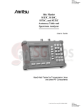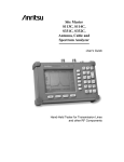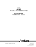
1
Site Master™
Models S114C and S332C
Antenna, Cable and Spectrum Analyzers
MAINTENANCE MANUAL
490 JARVIS DRIVE · MORGAN HILL, CA 95037-2809
P/N: 10580-00068
REVISION D
PRINTED: June 2009
COPYRIGHT ã 2002-2009 ANRITSU CO.
Table of Contents
1. INTRODUCTION . . . . . . . . . . . . . . . . . . . . . . . . . . . . . . . . . . . . . . . . 4
2. DESCRIPTION . . . . . . . . . . . . . . . . . . . . . . . . . . . . . . . . . . . . . . . . . 4
3. SITE MASTER FREQUENCY ACCURACY . . . . . . . . . . . . . . . . . . . . . . . . . . 4
4. RETURN LOSS VERIFICATION . . . . . . . . . . . . . . . . . . . . . . . . . . . . . . . . 5
5. SPECTRUM ANALYZER FREQUENCY ACCURACY . . . . . . . . . . . . . . . . . . . . 5
6. INTERNAL REFERENCE FREQUENCY ADJUSTMENT . . . . . . . . . . . . . . . . . . 6
7. SPECTRUM ANALYZER PHASE NOISE VERIFICATION . . . . . . . . . . . . . . . . . 7
8. SPECTRUM ANALYZER SECOND HARMONIC DISTORTION TEST . . . . . . . . . . . 9
9. SPECTRUM ANALYZER RESIDUAL SPURIOUS RESPONSE TEST . . . . . . . . . . . 10
10. SPECTRUM ANALYZER RESOLUTION BANDWIDTH ACCURACY TEST . . . . . . . 12
11. SPECTRUM ANALYZER MEASUREMENT ACCURACY TEST . . . . . . . . . . . . . 13
12. DISPLAYED AVERAGE NOISE LEVEL . . . . . . . . . . . . . . . . . . . . . . . . . . 16
13. SPECTRUM ANALYZER DYNAMIC RANGE TEST . . . . . . . . . . . . . . . . . . . . 17
14. POWER MONITOR VERIFICATION . . . . . . . . . . . . . . . . . . . . . . . . . . . . 18
15. TERMINATION VERIFICATION . . . . . . . . . . . . . . . . . . . . . . . . . . . . . . 19
16. INSTACAL MODULE VERIFICATION . . . . . . . . . . . . . . . . . . . . . . . . . . . 22
17. BATTERY PACK REMOVAL AND REPLACEMENT. . . . . . . . . . . . . . . . . . . . 23
18. BATTERY INFORMATION . . . . . . . . . . . . . . . . . . . . . . . . . . . . . . . . . 24
19. FRONT PANEL ASSEMBLY REMOVAL AND REPLACEMENT . . . . . . . . . . . . . 25
20. LCD ASSEMBLY REPLACEMENT . . . . . . . . . . . . . . . . . . . . . . . . . . . . . 26
21. KEY PAD PCB REPLACEMENT . . . . . . . . . . . . . . . . . . . . . . . . . . . . . . 26
22. KEY PAD MEMBRANE REPLACEMENT . . . . . . . . . . . . . . . . . . . . . . . . . 27
23. MAIN PCB ASSEMBLY REPLACEMENT . . . . . . . . . . . . . . . . . . . . . . . . . 27
24. REPLACEABLE PARTS . . . . . . . . . . . . . . . . . . . . . . . . . . . . . . . . . . . 28
Site Master S114C/S332C MM
i/ii
1.
(a) Press the Preset key, then select Preset All (F1).
INTRODUCTION
This manual provides maintenance instructions for
the Site Master Model S114C and S332C Antenna,
Cable, and Spectrum Analyzers. It describes the
product and provides performance verification procedures, parts replacement procedures, and a replaceable parts list.
2.
(b) Press the Frequency key.
(c) Press the 1 key and then the GHz key
to change the Center Frequency to 1
GHz.
(d) Press the Span key.
(e) Press the 7, 5, 0, and kHz keys sequentially to change the Frequency
Span to 750 kHz.
DESCRIPTION
The Site Master is a hand held SWR/RL (standing
wave ratio/return loss), Distance-To-Fault and spectrum analysis measurement instrument. It combines
a synthesized source, VSWR Bridge, receiver and
spectrum analyzer circuitry in a compact
instrument. An optional power monitor is also available.
(f) Press the RBW key.
(g) Press the 1, 0 and kHz keys sequentially to change the RBW to 10 kHz.
(h) Press the VBW key.
(i) Press the Filter Off soft key (F3) to
turn the VB filter off.
The following sections contain tests that can be used
to verify the performance of the Site Master models
S114C and S332C having any version of firmware.
3.
(j) Press the Amplitude key.
(k) Press the 0, and dBm keys sequentially to change the Reference Level
to 0 dBm.
SITE MASTER FREQUENCY ACCURACY
The following test can be used to verify the CW frequency accuracy of the Site Master. Measurement
calibration of the Site Master is not required for this
test.
a.
(l) Press the Log Scale soft key (F5)
(m) Select 2 dB/Div (F3) and the press the
return soft key (F6).
(n) Press the Marker key.
Equipment Required:
(o) Press the Zone Width soft key (F5).
· Spectrum Analyzer Anritsu Model
MS2663C or equivalent
(p) Select the Spot soft key (F1).
6.
b.
Procedure:
1.
Press and hold the ESCAPE/CLEAR key,
then press the ON/OFF key to turn on the
Site Master. (This sets the instrument to
the factory preset state.)
NOTE
Before continuing, allow a five minute warm
up for the internal circuitry to stabilize.
2.
Press the FREQ/DIST key, then press the
F1 soft key and set F1 to 1000 MHz, then
press the ENTER key.
3.
Press the F2 soft key, set F2 to 1000 MHz,
then press the ENTER key.
4.
Connect the RF cable from the Site Master Reflection Test Port to the RF Input
on the MS2663C or equivalent.
5.
Set up the Spectrum Analyzer as follows:
Site Master S114C/S332C MM
On the Site Master, press the SYS key,
the OPTIONS soft key and then the FIXED
CW soft key to turn Fixed CW on.
NOTE
If the Site Master has gone into the hold mode,
press the RUN/HOLD key to return to normal
mode.
7.
On the Spectrum Analyzer, press A, B
then the Storage soft key (F5).
8.
Press the MaxHold soft key (F2).
9.
When a smooth peak response appears
on the Spectrum Analyzer, press the
Marker Peak Search key on the Spectrum
Analyzer. Verify that the marker peak
readout value is 1000 MHz ±75 kHz.
10.
On the Site Master, press the SYS key,
the OPTIONS soft key and then the FIXED
CW soft key to turn Fixed CW Off.
1
4.
RETURN LOSS VERIFICATION
The following test can be used to verify the accuracy
of return loss measurements. Measurement calibration of the Site Master is required for this test.
a.
Equipment Required:
· 20 dB offset, Anritsu SC5270
b.
Procedure:
1.
Connect the 10 MHz reference source to
the Anritsu MG3692A Synthesized Signal Source.
2.
Connect the output of the source to the
RF Input of the Site Master.
3.
Connect the external power supply
(Anritsu part number 40-115) to the Site
Master.
4.
Press and hold the ESCAPE/CLEAR key,
then press the ON/OFF key to turn on the
Site Master. (This sets the instrument to
the factory preset state.)
5.
Turn on the 10 MHz reference source
and the Anritsu MG3692A Synthesized
Signal Source.
6.
Set the MG3692A output to 1000 MHz
CW for the S114C (2000 MHz CW for the
S332C), with an RF output level of 0
dBm.
· 6 dB offset, Anritsu SC5237
· Open/Short, Anritsu 22N50
· 50 Ohm Termination,
Anritsu 28N50-2 or SM/PL
b.
Procedure:
1.
Press and hold the ESCAPE/CLEAR key,
then press the ON/OFF key to turn on the
Site Master. (This sets the instrument to
the factory preset state.)
NOTE
Before continuing, allow a five minute warm
up for the internal circuitry to stabilize.
2.
Press the MODE key.
3.
Use the Up/Down arrow key to highlight
RETURN LOSS, then press ENTER.
4.
Press the START CAL key.
5.
Follow the instructions on the screen to
perform a calibration using a 22N50
Open/Short and 28N50-2 or SM/PL Termination.
6.
7.
5.
Connect the 20 dB offset to the Refl Test
Port and verify that the reading is 20 dB
± 1.7 dB.
Connect the 6 dB offset to the Refl Test
Port and verify that the reading is 6 dB
± 1.2 dB.
7.
On the Site Master, press the MODE key.
Use the up/down arrow key to highlight
SPECTRUM ANALYZER and press ENTER
to select spectrum analyzer mode.
8.
Press the AMPLITUDE key and the REF
LEVEL soft key.
9.
Enter 20 and press the ENTER key to set
the Reference Level to 20 dBm.
10.
Press the FREQ/DIST key and the CENTER
soft key.
11.
For the S114C, enter 1000 and press the
MHz soft key to set the center frequency
to 1000 MHz. For the S332C, enter 2000
and press the MHz soft key to set the center frequency to 2000 MHz.
12.
Press the SPAN soft key and enter 50.
Press the kHz soft key to set the span to
50 kHz.
13.
Press the SWEEP key.
14.
Press the RBW soft key and then the
MANUAL soft key. Use the Up/down arrow
key to select 10 kHz. Press ENTER to set
SPECTRUM ANALYZER FREQUENCY
ACCURACY
The following test can be used to verify the CW frequency accuracy of the Site Master Spectrum Analyzer.
a.
Equipment Required:
· Anritsu MG3692A Synthesized Signal
Source, with options 4 and 15A
· 10 MHz Reference Standard
2
NOTE
Before continuing, allow a 30-minute warm up
for the internal circuitry to stabilize.
the resolution bandwidth to 10 kHz and
press the BACK soft key.
Site Master S114C/S332C MM
15.
Press the VBW soft key and then the
MANUAL soft key. Use the Up/down arrow
key to select 3 kHz. Press ENTER to set
the video bandwidth to 3 kHz.
16.
Press the MARKER key, then the M1 soft
key.
17.
Select the EDIT soft key and use the
Up/down arrow key to center the marker
on the waveform. Verify that the marker
frequency is 1000 MHz, ± 2 kHz for the
S114C, or 2000 MHz ± 4 kHz for the
S332C.
NOTE
If the unit fails the Spectrum Analyzer Frequency Accuracy test, contact Anritsu
Customer Service.
6.
SPECTRUM ANALYZER PHASE NOISE
VERIFICATION
This test can be used to verify the phase noise of the
Site Master Spectrum Analyzer.
a.
Press the RBW soft key and the MANUAL
soft key. Use the Up/down arrow key to
select 10 kHz. Press ENTER to set the
resolution bandwidth to 10 kHz then
press the BACK soft key.
8.
Press the VBW soft key and the MANUAL
soft key. Use the Up/down arrow key to
select 3 kHz. Press ENTER to set the
video bandwidth to 3 kHz.
9.
Press the FREQ/DIST key and the CENTER
soft key.
10.
Enter 1000 and press the ENTER key to
set the center frequency to 1000 MHz.
11.
Press the SPAN soft key and enter 0.1.
Press the ENTER key to set the span to
0.100 MHz.
12.
Press the AMPLITUDE key.
13.
Press the REF LEVEL soft key and enter
–27. Press ENTER to set the reference
level to –27 dBm.
14.
Press the MARKER key, then the M1 soft
key.
15.
Press EDIT and enter 1000. Press ENTER
to set the M1 marker frequency to 1000
MHz.
16.
Press the BACK soft key and the M2 soft
key.
17.
Press EDIT and enter 1000.03. Press
ENTER to set the M2 marker frequency to
Equipment Required:
· Anritsu MG3692A Synthesized Signal
Source, with options 2A, 4 and 15A, or
equivalent
b.
7.
Procedure:
1.
2.
3.
Connect the output of the source to the
Site Master RF Input.
Connect the external power supply
(Anritsu part number 40-115) to the Site
Master.
Press and hold the ESCAPE/CLEAR key,
then press the ON/OFF key to turn on the
Site Master. (This sets the instrument to
the factory preset state.)
NOTE
Before continuing, allow a 30-minute warm up
for the internal circuitry to stabilize.
4.
Set the MG3692A output to 1000 MHz,
with an RF output level of –30 dBm.
5.
On the Site Master, press and hold the
ESCAPE/CLEAR key, then press the
ON/OFF key to turn on the Site Master.
(This sets the instrument to the factory
preset state.)
6.
Press the SWEEP key.
Site Master S114C/S332C MM
1000.03 MHz (30 kHz higher than the
center frequency).
18.
Press the DELTA (M2-M1) soft key.
19.
Press the RUN/HOLD key and read and
record the D 2 reading
20.
Press the RUN/HOLD key to read and record five values, then calculate the average of the five recorded values.
21.
Substract 40 dB from the average value
and verify that the result is £ –75
dBc/Hz. (For example: –35 dBc measured
– 40 dB = –75 dBc/Hz.)
22.
(For example: –35 dBc measured +
(-40 dB) = –75 dBc/Hz.)
3
NOTE
The measured value is converted to dBc/Hz using the following formula:
dBc / Hz = - measured dBc - 10log ( RBW
1Hz )
[
At 10 kHz RBW, 10log (
) = 40 , so
dBc / Hz = - measured dBc - 40.
]
3.
Connect the external power supply
(Anritsu part number 40-115) to the Site
Master.
4.
On the Site Master, press and hold the
ESCAPE/CLEAR key, then press the
ON/OFF key to turn on the Site Master.
(This sets the instrument to the factory
preset state.)
5.
Turn on the 10 MHz reference source
and the Anritsu MG3692A Synthesized
Signal Source.
6.
Set the MG3692A output to 40MHz CW,
with an RF output level of –30 dBm.
RBW
1Hz
23.
Press the BACK soft key and the M3 soft
key.
24.
Press the EDIT key and enter 999.970.
Press MHz to set the M3 marker frequency to 999.970 MHz (30 kHz lower
than the center frequency).
25.
Press the DELTA (M3-M1) soft key.
26.
Press the RUN/HOLD key. Read and record
the D 3 reading.
27.
Press the RUN/HOLD key to read and record five values, then calculate the average of the five recorded values.
28.
7.
Substract 40 dB from the average value
and verify that the result is £ –75
dBc/Hz. (For example: –35 dBc measured
– 40 dB = –75 dBc/Hz.)
SPECTRUM ANALYZER SECOND
HARMONIC DISTORTION TEST
7.
On the Site Master, press the MODE key.
Use the up/down arrow key to highlight
SPECTRUM ANALZYER and press ENTER
to select spectrum analyzer mode.
8.
Press the AMPLITUDE key and the REF
LEVEL soft key.
9.
Enter –27 and press the ENTER key to set
the Reference Level to –27 dBm.
10.
Press the SCALE soft key and enter 7
then press ENTER.
11.
Press the FREQ/DIST key and then the
CENTER soft key.
12.
Enter 40 and press the MHz soft key to
set the center frequency to 40 MHz.
13.
Press the SPAN soft key and enter 0.2.
Press the MHz soft key to set the span to
0.200 MHz.
· 10 MHz Reference Standard
14.
Press the SWEEP key.
· 50 MHz Low Pass Filter
15.
Press the RBW soft key and then the
MANUAL soft key. Use the Up/down arrow
key to select 10 kHz. Press ENTER to set
The following test can be used to verify the input related spurious response of the Site Master Spectrum
Analyzer.
a.
NOTE
Before continuing, allow a 30-minute warm up
for the internal circuitry to stabilize.
Equipment Required:
· Anritsu MG3692A Synthesized Signal
Source with options 2A, 4 and 15A, or
equilvalent
· RF coaxial cable, N male to N male
b.
4
the resolution bandwidth to 10 kHz and
select BACK.
Procedure:
1.
Connect the 10 MHz reference source to
the Anritsu MG3692A Synthesized Signal Source.
2.
Connect one end of the 50 MHz Low Pass
Filter to the output of the source and the
other end to the Site Master Spectrum
Analyzer RF Input with the RF coaxial
cable.
16.
Press the VBW soft key and then the
MANUAL soft key. Use the Up/down arrow
key to select 3 kHz. Press ENTER to set
the video bandwidth to 3 kHz.
17.
Press the MARKER key, then the M1 soft
key.
18.
Select the EDIT soft key, then enter 40.
Press the MHz soft key to set M1 to 40
MHz .
Site Master S114C/S332C MM
19.
On the MG3692A Synthesized Signal
Source, adjust the output level so that
the M1 reading of Site Master Spectrum
Analyzer is –30 dBm at 40 MHz.
3.
On the Site Master, press the MODE key.
Use the up/down arrow key to highlight
SPECTRUM ANALZYER and press ENTER
to select spectrum analyzer mode.
20.
On the Site Master, press the FREQ/DIST
key and then the CENTER soft key.
4.
Press the AMPLITUDE key and the REF
LEVEL soft key.
21.
Enter 80 and press the MHz soft key to
set the center frequency to 80 MHz.
5.
Enter –75 and press the ENTER key to set
the Reference Level to –75 dBm.
22.
Press the MARKER key and the M1 soft
key.
6.
Press the SCALE soft key and enter 5,
then press ENTER.
23.
Select the EDIT soft key, then enter 80.
Press the MHz soft key to set M1 to 80
MHz .
7.
Press the SWEEP key.
8.
Press the RBW soft key and then the
MANUAL soft key. Use the Up/down arrow
key to select 10 kHz. Press ENTER to set
24.
Record the amplitude of the signal at M1
80 MHz:
the resolution bandwidth to 10 kHz and
select BACK.
Second Harmonic Level @ 80 MHz =____dBm
9.
25.
Convert this measured value to dBc using the following formula:
Press the VBW soft key and then the
MANUAL soft key. Use the Up/down arrow
key to select 100 Hz and press ENTER to
set the video bandwidth to 100 Hz.
8.
Input Related Spurious Response (dBc) =
[Second Harmonic Level @ 80 MHz] +
30 dBm = ___ dBc
10.
Press the FREQ/DIST key and the START
soft key.
11.
Enter 500 and press the kHz soft key to
set the start frequency to 500 kHz.
Specifications for this measurement are –45
dBc with –30 dBm into the first mixer.
12.
Press the STOP soft key and enter 4, then
press the MHz soft key to set the stop frequency to 4 MHz.
13.
Wait till one full sweep is complete.
14.
Press the MARKER key and then the M1
soft key.
15.
Press the ON/OFF soft key and then the
MARKER TO PEAK soft key.
16.
Record the M1 amplitude reading and
verify whether it is less than or equal to
–90 dBm.
SPECTRUM ANALYZER RESIDUAL
SPURIOUS RESPONSE TEST
The following test can be used to verify the residual
spurious response of the Site Master Spectrum Analyzer.
a.
Equipment Required:
· Anritsu 28N50-2 or SM/PL 50 ohm Termination or equivalent
b.
Procedure:
1.
Connect the 50 ohm termination to the
Site Master RF Input.
2.
On the Site Master, press and hold the
ESCAPE/CLEAR key, then press the
ON/OFF key to turn on the Site Master.
(This sets the instrument to the factory
preset state.)
NOTE
Before continuing, allow a 30-minute warm up
for the internal circuitry to stabilize.
Site Master S114C/S332C MM
NOTE
If a spur with an amplitude larger than –90
dBm occurs, wait another full sweep and observe whether the spur occurs at the same
point on the second sweep. If the spur does not
occur at the same point on the second sweep,
then the spur on the first sweep was not real.
17.
Press the SWEEP key.
18.
Press the VBW soft key and then the
MANUAL soft key. Use the Up/down arrow
key to select 3 kHz and press ENTER to set
the video bandwidth to 3 kHz.
5
19.
Press the FREQ/DIST key and the START
soft key.
39.
Press the ON/OFF soft key and then the
MARKER TO PEAK soft key.
20.
Enter 4 and press the MHz soft key to set
the start frequency to 4 MHz.
40.
Record the M1 amplitude reading and
verify it is £ –90 dBm.
21.
Press the STOP soft key and enter 1000,
then press the MHz soft key to set the
stop frequency to 1000 MHz.
22.
Wait until one full sweep is complete.
23.
Press the MARKER key and then the M1
soft key.
24.
Press the ON/OFF soft key and then the
MARKER TO PEAK soft key.
25.
Record the M1 amplitude reading and
verify it is £ –90 dBm.
· Anritsu MG3692A Synthesized Signal
Source with options 2A, 4 and 15, or
equivalent
26.
Press the FREQ/DIST key and the START
soft key.
· 10 MHz Reference Standard
27.
Enter 1000 and press the MHz soft key to
set the start frequency to 1000 MHz.
28.
Press the STOP soft key.
29.
For the S114C, enter 1600, then press the
MHz soft key to set the stop frequency to
1600 MHz.
1.
Connect the 10 MHz reference source to
the Anritsu MG3692A Synthesized Signal Source.
For the S332C, enter 2000, then press
MHz soft key to set the stop frequency to
2.
Connect the output of the Anritsu
MG3692A Synthesized Signal Source to
the Site Master Spectrum Analyzer RF
Input.
3.
On the Site Master, press and hold the
ESCAPE/CLEAR key, then press the
ON/OFF key to turn on the Site Master.
(This sets the instrument to the factory
preset state.)
9.
SPECTRUM ANALYZER RESOLUTION
BANDWIDTH ACCURACY TEST
The following test can be used to verify the resolution bandwidth accuracy of the Site Master Spectrum Analyzer at four frequencies.
a.
Equipment Required:
· 3 GHz RF cable (Nm to Nm) or equivalent
b.
Procedure:
2000 MHz.
30.
Wait until one full sweep is complete.
31.
Press the MARKER key and then the M1
soft key.
32.
Press the ON/OFF soft key and then the
MARKER TO PEAK soft key.
33.
Record the M1 amplitude reading and
verify it is £ –90 dBm.
NOTE
Continue on to Step 34 only if the unit being
tested is a Model S332C Site Master.
6
34.
Press the FREQ/DIST key and the START
soft key.
35.
Enter 2000 and press the MHz soft key to
set the start frequency to 2000 MHz.
36.
Press the STOP soft key and enter 3000,
then press the MHz soft key to set the
stop frequency to 3000 MHz.
37.
Wait until one full sweep is complete.
38.
Press the MARKER key and then the M1
soft key.
NOTE
Before continuing, allow a 30-minute warm up
for the internal circuitry to stabilize.
4.
Set the MG3692A output to 1 GHz, with
an RF output level of –30 dBm.
5.
On the Site Master, press the MODE key.
Use the up/down arrow key to highlight
SPECTRUM ANALZYER and press ENTER
to select spectrum analyzer mode.
6.
Press the AMPLITUDE key and the REF
LEVEL soft key.
7.
Enter –27 and press the ENTER key to set
the Reference Level to –27 dBm.
8.
Press the SCALE soft key and enter 3,
then press ENTER.
Site Master S114C/S332C MM
9.
Press the FREQ/DIST key and the CENTER
soft key.
10.
Enter 1 and press the GHz soft key to set
the center frequency to 1GHz.
NOTE
The Measured Occupied BW value for each
RBW setting can be recorded in Table 1.
30 kHz RBW Test
23.
Press the FREQ/DIST key.
24.
Press the SPAN soft key, enter .1 and
press the MHz soft key to set the span to
0.1 MHz.
25.
Press the SWEEP key.
26.
Press the RBW soft key and then the
MANUAL soft key. Use the Up/down arrow
key to select 30 kHz. Press ENTER to set
1 MHz RBW Test
11.
Press the SPAN soft key, enter 5 and press
the MHz soft key to set the span to 5
MHz.
12.
Press the SWEEP key.
13.
Press the RBW soft key and then the
MANUAL soft key. Use the Up/down arrow
key to select 1 MHz. Press ENTER to set
the resolution bandwidth to 1 MHz and
select BACK.
14.
Press the VBW soft key and then the
MANUAL soft key. Use the Up/down arrow
key to select 3 kHz and press ENTER to set
the video bandwidth to 3 kHz.
15.
Press the MEASURE soft key, the OBW soft
key and then the METHOD soft key to
measure a 3 dB bandwidth.
16.
Press the MEASURE soft key and read the
displayed Meas Occ BW value. The Meas
Occ BW value should be ± 20% of the
RBW.
the resolution bandwidth to 30 kHz and
select BACK.
27.
Press the MEASURE soft key, the OBW
soft key and then the METHOD soft key to
measure a 3 dB bandwidth.
28.
Press the MEASURE soft key and read the
displayed Meas Occ BW value. The Meas
Occ BW value should be ± 20% of the
RBW.
10 kHz RBW Test
29.
Press the FREQ/DIST
30.
Press the SPAN soft key, enter .04 and
press the MHz soft key to set the span to
0.04 MHz.
31.
Press the SWEEP key.
32.
Press the RBW soft key and then the EDIT
soft key. Use the Up/down arrow key to
select 10 kHz. Press ENTER to set the resolution bandwidth to 10 kHz and select
BACK.
33.
Press the MEASURE soft key, the OBW
soft key and then the METHOD soft key to
measure a 3 dB bandwidth.
34.
Press the MEASURE soft key and read the
displayed Meas Occ BW value. The Meas
Occ BW value should be ± 35% of the
RBW.
100 kHz RBW Test
17.
Press the FREQ/DIST key.
18.
Press the SPAN soft key, enter 1 and press
the MHz soft key to set the span to 1
MHz.
19.
Press the SWEEP key.
20.
Press the RBW soft key and then the
MANUAL soft key. Use the Up/down arrow
key to select 100 kHz. Press ENTER to set
the resolution bandwidth to 100 kHz and
select BACK.
21.
22.
Table 1.
RBW
Setting
Press the MEASURE soft key, the OBW soft
key and then the METHOD soft key to
measure a 3 dB bandwidth.
1 MHz
Press the MEASURE soft key and read the
Meas Occ BW value. The Meas Occ BW
value should be ± 20% of the RBW.
Site Master S114C/S332C MM
RBW Check
Lower
Limit
Measured
Value
Upper
Limit
0.8 MHz
1.2 MHz
100 kHz
80 kHz
120 kHz
30 kHz
24 kHz
36 kHz
10 kHz
6.5 kHz
13.5 kHz
7
10. SPECTRUM ANALYZER MEASUREMENT
ACCURACY TEST
This test verifies the level accuracy of the Site Master Spectrum Analyzer.
a.
3.
Connect the external power supply
(Anritsu part number 40-115) to the Site
Master.
4.
On the Site Master, press and hold the
ESCAPE/CLEAR key, then press the
ON/OFF key to turn on the Site Master.
(This sets the instrument to the factory
preset state.)
5.
Turn on the power meter and signal
source.
Equipment Required:
· Anritsu MG3692A Synthesized Signal
Source, with options 2A, 4 and 15A
· Anritsu ML2430A-Series Power Meter or
equivalent
NOTE
Before continuing, allow a 30-minute warm up
for the internal circuitry to stabilize.
· Anritsu MA2442A High Accuracy Power
Sensor or equivalent
· Anritsu N241A50 Power Splitter or
equivalent
6.
On the Site Master, press the MODE key.
Use the up/down arrow key to highlight
SPECTRUM ANALZYER and press ENTER
to select spectrum analyzer mode.
7.
Press the SWEEP key.
8.
Press the RBW soft key and then the
MANUAL soft key. Use the Up/down arrow
key to select 10 kHz. Press ENTER to set
the resolution bandwidth to 10 kHz.
9.
Press BACK, then the VBW soft key and
then the MANUAL soft key. Use the
Up/down arrow key to select 3 kHz. Press
ENTER to set the video bandwidth to 3
kHz.
10.
Press BACK, then MEASURE, then DETECTION, then AVERAGE.
11.
Press the FREQ/DIST key.
· Anritsu 34NN50A 50 ohm adapter or
equivalent
· Anritsu 34RSN50 50 ohm adapter or
equivalent
· Anritsu 15NNF50-1.5C RF Coaxial Cable
or equivalent
b.
Procedure:
1.
Connect the power sensor to the power
meter and calibrate the sensor.
2.
Using the power splitter, coaxial cable
and adapters, connect the Site Master to
the signal source and the power sensor
as shown in Figure 1.
ML2438A POWER METER
C le a r
E n try
F re q u e n c y
MA2442A
SENSOR
B a c k
S p a c e
L e v e l
7
8
M o d u la tio n
4
S y s te m
1
L in e
9
5
6
2
0
O u tp u t
.
3
O n O ff
R F O u tp u t
5 0 9
15NNF50-1.5C
+ /-
N241A50
O p e ra te
S ta n d b y
MG3692A SOURCE
34NN50A
ADAPTER
34RSN50 ADAPTER
Site Master S332C
1
AUTO
SCALE
RECALL
SETUP
3
5
LIMIT
7
SAVE
DISPLAY
9
ON
OFF
MODE
FREQ/DIST
AMPLITUDE
2
START
CAL
SAVE
SETUP
ESCAPE
CLEAR
4
6
MARKER
8
RECALL
DISPLAY
0
ENTER
RUN
HOLD
+/-
PRINT
.
SYS
SWEEP
S332C
Figure 1.
8
Measurement Accuracy Setup
Site Master S114C/S332C MM
12.
Press the SPAN soft key and enter .5,
then press the MHz key to set the span to
.5 MHz.
13.
Press the AMPLITUDE key.
14.
Press the REF LEVEL soft key, enter 20
and press the ENTER key to set the reference level to +20 dBm.
15.
Press the FREQ/DIST key and the CENTER
soft key.
16.
Enter 50 and press the MHz soft key to
set the center frequency to 50 MHz.
17.
On the Anritsu ML2430A-Series Power
Meter, press the Sensor key and then the
CalFactor soft key. Select the FREQ soft
key and enter 50 MHz for the Input Signal Frequency. This sets the power meter
to the proper power sensor cal factor.
18.
Set the MG3692A output to 50 MHz CW
and the power level to +10 dBm as indicated on the power meter.
NOTE
To insure accuracy, set the output of the signal
source using the power meter reading. Do not
rely on the signal source display.
19.
Press the MARKER key, then the M1 soft
key.
20.
Select the MARKER TO PEAK soft key to
position the marker at the center of the
response for the test frequency.
NOTE
Table 2 can be used to record the results of
this test for future reference.
21.
Verify that the M1 reading is ± 2 dB
maximum from the input signal.
22.
Press the AMPLITUDE key.
23.
Press the REF LEVEL soft key, enter 0 and
press ENTER to set the reference level to
0 dBm.
24.
Set the MG3692A power level to –10
dBm as indicated on the power meter.
25.
Verify that the M1 reading is ± 2 dB
maximum from the input signal.
26.
Press the AMPLITUDE key.
27.
Press the REF LEVEL soft key, enter –20
and press ENTER to set the reference
level to –20 dBm.
Site Master S114C/S332C MM
28.
Set the MG3692A power level to –30
dBm as indicated on the power meter.
29.
Verify that the M1 reading is ± 2 dB
maximum from the input signal.
30.
Press the AMPLITUDE key.
31.
Press the REF LEVEL soft key and enter
–40. Press ENTER to set the reference
level to –40 dBm.
32.
Set the MG3692A power level to –50
dBm as indicated on the power meter.
33.
Verify that the M1 reading is ± 2 dB
maximum from the input signal.
34.
Repeat steps 15 through 33 for frequencies of 500 MHz, 1000 MHz, 1500 MHz,
2000 MHz, 2500 MHz and 2950 MHz.
Table 2. Measurement Accuracy Test Results
Power
Level
(dBm)
Site Master
Ref Level
(dBm)
50
+10
–10
–30
–50
+20
+20
–20
–40
500
+10
–10
–30
–50
+20
+20
–20
–40
1000
+10
–10
–30
–50
+20
+20
–20
–40
1500
+10
–10
–30
–50
+20
+20
–20
–40
+10
–10
–30
–50
+20
+20
–20
–40
+10
–10
–30
–50
+20
+20
–20
–40
+10
–10
–30
–50
+20
+20
–20
–40
Freq (MHz)
2000
(S332C only)
2500
(S332C only)
2950
(S332C only)
M1 Reading
9
11. DISPLAYED AVERAGE NOISE LEVEL
The following test can be used to verify the displayed
average noise level of the Site Master Spectrum Analyzer.
a.
Equipment Required:
· Anritsu 28N50-2 or SM/PL 50 ohm Termination or equivalent
b.
Enter 100 and press the kHz soft key to
set the start frequency to 100 kHz.
14.
Press the STOP soft key and enter 500,
then press the kHz soft key to set the stop
frequency to 500 kHz.
15.
Wait until a full sweep is complete.
16.
Press the MARKER key and then press
the M1 soft key.
17.
Press the MARKER TO PEAK soft key. Record the M1 amplitude reading and verify it is £ –80 dBm.
18.
Press the FREQ/DIST key and the START
soft key.
19.
Enter 500 and press the kHz soft key to
set the start frequency to 500 kHz.
20.
Press the STOP soft key and enter 4, then
press the MHz soft key to set the stop frequency to 4 MHz.
21.
Wait until a full sweep is complete.
22.
Press the MARKER key and then press
the M1 soft key.
23.
Press the MARKER TO PEAK soft key. Record the M1 amplitude reading and verify it is £ –95 dBm.
24.
Press the SWEEP key.
25.
Press the VBW soft key, and then the
MANUAL soft key. Use the Up/down arrow
key to select 3 kHz, and press ENTER to
Procedure:
1.
Connect the 50 ohm termination to the
Site Master Spectrum Analyzer RF Input.
2.
On the Site Master, press and hold the
ESCAPE/CLEAR key, then press the
ON/OFF key to turn on the Site Master.
(This sets the instrument to the factory
preset state.)
NOTE
Before continuing, allow a 30-minute warm up
for the internal circuitry to stabilize.
3.
On the Site Master, press the MODE key.
Use the up/down arrow key to highlight
SPECTRUM ANALZYER and press ENTER
to select spectrum analyzer mode.
4.
Press the AMPLITUDE key and the REF
LEVEL soft key.
5.
Enter –75 and press the ENTER key to set
the Reference Level to –75 dBm.
6.
Press the SCALE soft key and enter 5,
then press ENTER.
7.
Press the SWEEP key and then the MEASURE soft key.
8.
Press the DETECTION soft key, then press
AVERAGE soft key.
9.
Press the SWEEP key.
10.
11.
12.
10
13.
Press the RBW soft key and then the
MANUAL soft key. Use the Up/down arrow
key to select 10 kHz. Press ENTER to set
the resolution bandwidth to 10 kHz and
select BACK.
Press the VBW soft key and then the
MANUAL soft key. Use the Up/down arrow
key to select 100 Hz and press ENTER to
set the video bandwidth to 100 Hz.
Press the FREQ/DIST key and the START
soft key.
set the video bandwidth to 3 kHz.
26.
Press the FREQ/DIST key and the START
soft key.
27.
Enter 4 and press the MHz soft key to set
the start frequency to 4 MHz.
28.
Press the STOP soft key and enter 1000,
then press the MHz soft key to set the
stop frequency to 1000 MHz.
29.
Wait until a full sweep is complete.
30.
Press the MARKER key and then press
the M1 soft key.
31.
Press the MARKER TO PEAK soft key. Record the M1 amplitude reading and verify it is £ –95 dBm.
32.
Press the FREQ/DIST key and the START
soft key.
33.
Enter 1000 and press the MHz soft key to
set the start frequency to 1000 MHz.
Site Master S114C/S332C MM
34.
Press the STOP soft key.
35.
For the S114C, enter 1600 then press the
MHz soft key to set the stop frequency to
1600 MHz.
1.
Connect the output of the Power Splitter
to the RF In port of the Site Master Spectrum Analyzer.
For the S332C, enter 2000 then press the
MHz soft key to set the stop frequency to
2.
Connect the output of the both signal
sources to the input of the Power Splitter.
Turn on both sources.
b.
Procedure:
2000 MHz.
36.
Wait until a full sweep is complete.
3.
37.
Press the MARKER key and then press
the M1 soft key.
4.
38.
Press the MARKER TO PEAK soft key. Record the M1 amplitude reading and verify it is £ –95 dBm.
NOTE
Continue to Step 39 only if the unit is a Site
Master Model S332C.
(This sets the instrument to the factory
preset state.)
NOTE
Before continuing, allow a 30-minute warm up
for the internal circuitry to stabilize.
39.
Press the FREQ/DIST key and the START
soft key.
5.
Set the CW frequency of the first source
to 1.0 GHz.
40.
Enter 2000 and press the MHz soft key to
set the start frequency to 2000 MHz.
6.
Set the CW frequency of the second
source to 1.2 GHz.
41.
Press the STOP soft key and enter 3000,
then press the MHz soft key to set the
stop frequency to 3000 MHz.
7.
On the Site Master, press the MODE key.
Use the up/down arrow key to highlight
SPECTRUM ANALZYER and press ENTER
to select spectrum analyzer mode.
42.
Wait until a full sweep is complete.
8.
Press the FREQ/DIST key.
43.
Press the MARKER key and then press
the M1 soft key.
9.
44.
Press the MARKER TO PEAK soft key. Record the M1 amplitude reading and verify it is £ –95 dBm.
Press the CENTER soft key, enter 1100,
then press the MHz soft key to set the
center frequency to 1100 MHz.
12. SPECTRUM ANALYZER DYNAMIC
RANGE TEST
This test can be used to verify the dynamic range of
the Site Master spectrum analyzer.
a.
On the Site Master, press and hold the
ESCAPE/CLEAR key, then press the
ON/OFF key to turn on the Site Master.
Equipment required:
· Two Anritsu MG3692A Synthesized Signal Sources with options 2A, 4 and 15A,
or equivalent
· Anritsu N241A50 Power Splitter or
equivalent
· Anritsu 34NN50A 50 ohm adapter or
equivalent
· Anritsu 34RSN50 50 ohm adapter or
equivalent
Site Master S114C/S332C MM
10.
Press the SPAN soft key and enter 500,
then press the MHz key to set the span to
500 MHz.
11.
Press the AMPLITUDE key and then the
REF LEVEL soft key.
12.
Enter –20 and then press the ENTER key
to set the reference level to –20 dBm.
13.
Press the SWEEP key.
14.
Press the RBW soft key and then the
MANUAL soft key. Use the Up/down arrow
key to select 30 kHz, the press ENTER to
set the resolution bandwidth to 30 kHz.
15.
Press BACK, then the VBW soft key and
then the MANUAL soft key. Use the
Up/down arrow key to select 30 kHz, then
press ENTER to set the video bandwidth
to 30 kHz.
11
16.
Adjust the signal levels of both signal
sources so that both signal peaks are at
–20 dBm as indicated on the Site Master
Spectrum Analyzer display.
b.
Procedure
1.
Connect the DC power supply to the
MA2418A Reference Source (Figure 2).
2.
Connect the MA2418A Reference Source
to the input of the 560-7N50B RF detector.
3.
Connect the RF Detector output to the
RF Detector input of the Site Master.
4.
Connect the DC power supply to the appropriate line voltage to supply power to
the MA2418A Reference Source.
5.
Press and hold the ESCAPE/CLEAR key,
then press the ON/OFF key to turn on the
Site Master. (This sets the instrument to
the factory preset state.)
13. POWER MONITOR VERIFICATION
6.
Press the MODE soft key.
If the Power Monitor (Option 5) is installed in the
Site Master, the following test can be used to verify
the accuracy of the power measurements. Measurement calibration of the Site Master is not required
for this test.
7.
Use the Up/Down arrow key to highlight
POWER MONITOR, then press ENTER.
8.
Press the ZERO soft key to zero the power
monitor. When complete, ZERO ADJ:ON is
displayed in the message area.
9.
Verify that the power monitor reading is
0.0 dBm ± 1 dB.
10.
Connect the output of the MA2418A Reference Source to the two attenuators so
as to add 40 dB of attenuation (Figure 2).
11.
Connect the MA2418A Reference Source
and the attenuators to the input of the
560-7N50B RF detector.
12.
Verify that the power monitor reading is
now –40.0 dBm ±2 dB.
17.
Referring to steps 13 through 15, set the
RBW to 10 kHz and the VBW to 1 kHz.
18.
Wait until the sweep is complete, then
reduce the power level of the second
source signal to below –85 dBm and verify that the signal is visible at below –85
dBm.
NOTE
Be sure to wait until the sweep is complete before changing the power level of the second
source.
a.
Equipment Required:
· RF Detector, 10 MHz to 20 GHz,
Anritsu 560-7N50B
· 10 dB Attenuator, Weinschel 1-10
· 30 dB Attenuator, Weinschel 1-30
· RF Reference Source, 0.050 GHz,
Anritsu MA2418A
· DC Power Supply, Anritsu 2000-933
Attenuators
560-7N50B
RF Detector
MA2418A Reference Source
50 MHz, 50 W
0dBm
15-24V DC
20 mA
MA2418A
Reference Source
Site Master S331B
1
2
START
CAL
AUTO
SCALE
SAVE
SETUP
RECALL
SETUP
3
5
LIMIT
7
SAVE
DISPLAY
9
ON
OFF
MODE
FREQ/DIST
AMPLITUDE
ESCAPE
CLEAR
4
6
DC Power Supply 2000-933
MARKER
8
RECALL
DISPLAY
0
ENTER
RUN
HOLD
+/-
PRINT
.
SYS
SWEEP
Site Master w/ Option 5 Installed
Figure 2.
12
Power Monitor Verification
Site Master S114C/S332C MM
14. TERMINATION VERIFICATION
This test verifies the accuracy of the Site Master
SM/PL termination using the precision return loss
mode of the 541XXA Scalar Measurement System.
Measurements of terminations using this mode provide results that are traceable to the NIST (National
Institute of Standards and Technology) standards for
the precision airline.
a.
4.
Using the Menu up-down keys: Highlight
RESET, then press the Select key.
5.
At the RESET MENU display, use the
Menu up-down keys to highlight RESET
TO FACTORY DEFAULTS, then press the
Select key.
6.
Set the signal source for the frequency
range as follows:
(a) Press the Frequency key.
Equipment Required:
(b) Using the Data Entry Keypad or
Data Entry Knob, set the Start frequency to 0.01 GHz. Press the Enter
key.
· Scalar Measurement System,
Anritsu 541XXA
· Offset SWR Autotester,
Anritsu 560-97A50-20
(c) Using the Data Entry Keypad or
Data Entry Knob, set the Stop frequency to 4.0 GHz. Press the Enter
key.
· Precision Airline, Anritsu 18N50
· Open/Short, Anritsu 22N50
· 50 Ohm Termination, Anritsu 28N50-2
7.
Press the Channel 2 Display On/Off key
to Off.
8.
Press the Channel 1 Menu key.
· Source Adapter, Anritsu 34NN50A
b.
Procedure
1.
9.
Connect the test equipment as shown in
Figure 3.
2.
Press the Power key on the 541XXA to
On.
3.
Press the System Menu key.
Using the Menu up-down keys: Highlight
PRECISION RL, then press the Select key.
10.
At the PRECISION RETURN LOSS
menu display, use the Menu up-down
keys to highlight FINAL, then press the
Select key.
11.
Press the Calibration key.
Open/Short
50 Ohm
Termination
Termination
under Test
541XXA Scalar Measurement System
Beadless
End
Precision
Air Line
Connect Dashed Line Connections
When Directed By Procedure
A
B
Source
Adapter
Figure 3.
Offset SWR
Autotester
541XXA Precision Return Loss Setup
Site Master S114C/S332C MM
13
12.
13.
14.
At the CALIBRATION menu display, use
the Menu up-down keys to highlight
START CAL, then press the Select key.
Press the Select key when ready.
16.
At the PRECISION RETURN LOSS
CALIBRATION menu prompt, connect
the Open to the beadless end of the airline. Press the Select key to start the calibration.
19.
14
+ 0 .0 d B
At the next menu prompt, remove the
Open and connect the Short to the
beadless end of the airline. Press the Select key to start the calibration process.
At the next menu prompt, remove the
Short and connect the 50 Ohm Termination to the beadless end of the air line.
Press the Select key to start the calibration process.
20.
When the calibration is complete, remove
the 50 Ohm Termination.
21.
Connect the SM/PL termination to the
beadless end of the air line and press the
Select key to begin the measurement.
22.
Observe that the waveform displayed resembles that shown in Figure 5.
23.
Press the Cursor On/Off key to On.
5 4 1 4 7 A
C O N N E C T O P E N
T O A IR L IN E
P R E S S S E L E C T
W H E N R E A D Y
S T A R T : 0 .0 1 0 0 G H z
4 0 1 p ts
Figure 4.
0 .4 G H z /D IV
S T O P : 4 .0 0 0 0 G H z
L E V E L + 7 .0 d B m
Example of a Good Connection
24.
Observe the Cursor menu readout. The
minimum return loss reading for the
SM/PL termination should be 42 dB.
1 : P R E C S N R L (A )
2 : O F F
1 0 .0 d B /D IV
O F F S E T
+ 0 .0 d B
5 4 1 4 7 A
C U R S O R
1 : -4 6 .0 2 d B
Verify that the display resembles that
shown in Figure 4, page 14.
CAUTION
During both calibration and measurement, be sure to properly
align the beadless connector of the
airline. When the connectors are
mis-aligned, a spike will usually
be visible on the display.
18.
O F F S E T
Connect the precision air line to the Offset SWR Autotester test port. Position
the air line pointing vertically upward.
Downward or horizontal positions make
connector pin alignment difficult.
15.
1 0 .0 d B /D IV
P R E C IS IO N
R E T U R N L O S S
C A L IB R A T IO N
At the PRECISION RETURN LOSS
CALIBRATION menu display prompt,
connect the Offset SWR Autotester to
Input A, if you have not done so yet.
NOTE
Ensure that the beadless end of the precision
airline is at the measurement connection
point.
17.
1 : P R E C S N R L (A )
2 : O F F
2 .4 0 5 0 G H z
P R E S S S E L E C T
F O R
C U R S O R M E N U
S T A R T : 0 .0 1 0 0 G H z
4 0 1 p ts
Figure 5.
0 .4 G H z /D IV
S T O P : 4 .0 0 0 0 G H z
L E V E L + 7 .0 d B m
Direct Readout of the Precision Return Loss
15. INSTACAL MODULE VERIFICATION
This test verifies the performance of the Anritsu Site
Master InstaCal Calibration Module. The InstaCal
Module, part number ICN50, is an optional accessory
for the S114C and S332C.
NOTE
Full verification of the InstaCal module over
its entire frequency range (2 - 4000 MHz) requires both an S114C and S332C Site Master.
However, limited verification is possible with
either instrument for the frequency range of
that instrument only. The frequency range of
the S114C is 2 to 1600 MHz. The frequency
range of the S332C is 25 to 4000 MHz.
Site Master S114C/S332C MM
a.
Equipment Required:
· InstaCal Module, part number ICN50
· 20 dB offset, Anritsu SC5270
· 6 dB offset, Anritsu SC5237
b.
Selecting the NO soft key will temporarily
transfer only the portion of the characterization data necessary for this particular calibration. This transfer takes aproximately 30 to 60
seconds, and will have to be repeated every
time a calibration is done using this combination of Site Master and InstaCal module.
Procedure
NOTE
If performing full verification over the entire
frequency range with both an S114C and
S332C Site Master, perform this procedure
first on the S114C and then on the S332C.
1.
Press and hold the ESCAPE/CLEAR key,
then press the ON/OFF key to turn on the
Site Master. (This sets the instrument to
the factory preset state.)
NOTE
Before continuing, allow a five minute warm
up for the internal circuitry to stabilize.
2.
Press the MODE soft key.
3.
Use the Up/Down arrow key to highlight
RETURN LOSS, then press ENTER.
4.
Press the START CAL key. The message
“CONNECT OPEN or InstaCal TO RF
Out PORT” will appear in the display.
5.
Connect the InstaCal module to the RF
Out port and press the ENTER key.
6.
Verify that the calibration has been properly performed by checking that the CAL
ON! message is displayed in the upper
left corner of the display.
7.
Remove the InstaCal module from the
RF Out port and connect the 20 dB Offset to the RF Out port.
8.
Measure the return loss of the 20 dB Offset. The level should be 20 dB, ±2 dB
across the calibrated frequency range.
9.
Remove the 20 dB Offset from the RF
Out port and connect the 6 dB Offset to
the RF Out port.
10.
Measure the return loss of the 6 dB Offset. The level should be 6 dB, ±1.2 dB
across the calibrated frequency range.
NOTE
If this particular InstaCal module has been
used to calibrate this Site Master before, the
Site Master senses the familiar InstaCal
module and automatically calibrates the unit
using the OSL procedure.
If the Site Master senses that the
characterization data for the InstaCal module
connected to this Site Master is different than
the one currently stored, it will display soft
key options to keep or replace the InstaCal
characterization data.
Selecting the YES soft key transfers all of the
characterization data from this InstaCal
module to the Site Master. The transfer may
take up to three minutes. This option is
preferred if this InstaCal module is to stay
with this particular Site Master. Once
completed, the data will not need to be
transfered again for this combination of Site
Master and InstaCal module.
Site Master S114C/S332C MM
15
16. BATTERY PACK REMOVAL AND
REPLACEMENT
This procedure provides instructions for removing
and replacing the Site Master battery pack.
NOTE
Procedures in this manual may apply to many
similar instruments. Photos and illustrations
used are representative and may show instruments other than the S114C or S332C.
1.
With the Site Master standing upright on a
stable surface, locate the battery access door
(Figure 9).
Figure 7.
Removing the Battery Access Door
Figure 8.
Removing the Battery
BATTERY ACCESS DOOR
Figure 9.
2.
Battery Access Door Location
Lift up the access door handle and rotate it
90 degrees counterclockwise, as illustrated in
Figure 6.
5.
Replacement is the opposite of removal. Note
the orientation of the battery contacts, and
be sure to insert the new battery with the
contacts facing the rear of the unit (Figure
10).
BATTERY CONTACTS
Figure 6.
16
Rotate the Battery Access Door Handle
3.
Lift the door and remove, as illustrated in
Figure 7.
4.
Grasp the battery lanyard and pull the battery straight up and out of the unit, as illustrated in Figure 8.
Figure 10.
Battery Orientation
Site Master S114C/S332C MM
17. BATTERY INFORMATION
The following information relates to the care and
handling of the Site Master battery, and NiMH batteries in general.
· The Nickel Metal Hydride (NiMH) battery supplied with the Site Master is shipped in a discharged state. Beore using the Site Master, the
internal battery must first be charged for three
hours, either in the Site Master or in the optional battery charger (Anritsu part number:
2000-1029).
· Use only Anritsu approved battery packs.
· Recharge the battery only in the Site Master or
in an Anritsu approved charger.
· With a new NiMH battery, full performance is
achieved after three to five complete charge and
discharge cycles.
· When the Site Master or the charger is not in
use, disconnect it from the power source.
· Do not charge batteries for longer than 24
hours; overcharging may shorten battery life.
17.1.
Battery Testing Procedure
1.
NOTE
If the Battery Charging LED does not light,
the battery may be to low to immediately start
full charging. Leaving the unit connected to
AC power for several hours may bring the battery up to a level where full charging can begin. Turn the unit off and back on to see if the
Battery Charging LED lights indicating a full
charge cycle has begun.
2.
the battery is fully charged.
3.
Press and hold the ESCAPE/CLEAR key,
then press the ON/OFF key to turn on the
Site Master. This sets the instrument to
the factory preset state. Press ENTER
when prompted to continue.
4.
Press the SYS key, followed by the
STATUS soft key. Verify that the indicated
battery charge is ³ 80%. If the value is
80% or above, press the ESCAPE/CLEAR
key and continue with this procedure.
· Discharge an NiMH battery from time to time
to improve battery performance and battery life.
If the value is lower than 80%, a discharge/charge cycle may be needed to improve the battery capacity. Completely
discharge the battery, as described in
Steps 5 and 6 below, and then recharge
the battery as described in Steps 1 and 2.
If the battery capacity does not increase
after a discharge/charge cycle, replace
the battery.
· The battery can be charged and discharged hundreds of times, but it will eventually wear out.
· The battery may need to be replaced when the
operating time between charging becomes noticeably shorter than normal.
· Never use a damaged or worn out charger or
battery.
· Storing the battery in extreme hot or cold places
will reduce the capacity and lifetime of the battery.
5.
Press the START CAL key (to keep the
Site Master from going into HOLD mode)
and make note of the test start time.
6.
When the Site Master display fades and
the Site Master switches itself off, make
note of the test stop time.
7.
The total test time (Step 5 to Step 6)
should be ³ 2.5 hours. If the battery
charge is near 80% and the total test
time is <2.5 hours, replace the battery.
· Never short-circuit the battery terminals.
· Do not drop, mutilate or attempt to disassemble
the battery.
· Do not dispose of batteries in a fire!
· Batteries must be recycled or disposed of properly. Do not place batteries in household garbage.
· Always use the battery for its intended purpose
only.
Site Master S114C/S332C MM
Disconnect the AC-DC Adapter when the
Battery Charging LED turns off, indicating
· If left unused a fully charged battery will discharge itself over time.
· Temperature extremes will affect the ability of
the battery to charge: allow the battery to cool
down or warm up as necessary before use or
charging.
With the Site Master off and the battery
installed, connect the Universal AC
Adapter to the 12.5-15VDC (1100 mA) connector. The External Power LED and the
Battery Charging LED will light.
17
18. FRONT PANEL ASSEMBLY REMOVAL
AND REPLACEMENT
8.
Remove the front panel assembly.
This procedure provides instructions for removing
and replacing the Site Master front panel assembly.
With the front panel assembly removed, the LCD
display, keypad PCB, keypad membrane, and main
PCB assemblies can be removed and replaced.
J15
J4
1.
Place the Site Master face up on a work surface.
2.
Remove the four rubber corner bumpers by
carefully sliding the bumpers off of the case
corners (Figure 11).
J12
Figure 12.
9.
Site Master Front Panel Cable Connections
Reverse the above steps to replace the front
panel assembly.
NOTE
The corner bumpers only mount one way. That
is, the raised area inside one end of the
bumper (Figure 12) is made to conform to the
contour of the front cover only.
Figure 11.
3.
4.
Removing the Corner Bumpers
With the bumpers removed, the access holes
for the case screws are revealed. Use a Phillips screwdriver to remove the four screws
securing the two halves of the Site Master
case together.
Carefully lift up on the right side (as viewed
from the front) of the front half of the case
and begin to separate the two halves.
CAUTION
Do not force or pull the two halves of the case
apart as there are delicate cables attached between the two halves that must be disconnected first.
18
RAISED AREA
5.
Carefully depress the latch tab and disconnect the LCD display cable from J12 on the
main PCB.
6.
Carefully disconnect the keypad interface cable from J4 on the main PCB.
7.
Carefully disconnect the LCD display
backlight cable from J15 on the main PCB.
Figure 13.
Corner Bumper Detail
Site Master S114C/S332C MM
19. LCD ASSEMBLY REPLACEMENT
20. KEY PAD PCB REPLACEMENT
This procedure provides instructions for removing
and replacing the Liquid Crystal Display (LCD) once
the front panel assembly has been separated from
the Site Master.
This procedure provides instructions for removing
and replacing the key pad PCB.
1.
2.
3.
4.
1.
Remove the front panel assembly as directed
in section 18.
Remove the front panel assembly as directed
in section 18.
2.
Place the front panel assembly face down on
a protected work surface.
Place the front panel assembly face down on
a protected work surface.
3.
Remove the 14 Phillips screws that attach
the backing plate to the front panel assembly.
Remove the 14 Phillips screws that attach
the backing plate to the front panel assembly.
4.
Release the LCD display cable from the retaining clip on the front panel backing plate
(Figure 14).
5.
Remove the front panel backing plate, carefully feeding the LCD cable through the access hole to avoid damage to the cable or connector.
6.
Remove the rubber cushion pad from the key
pad PCB and remove the PCB.
Release the LCD display cable from the retaining clip on the front panel backing plate.
FRONT PANEL
BACKING PLATE
LCD CABLE
RETAINING CLIP
KEYPAD PCB
Figure 14.
Front Panel Backing Plate
5.
Remove the front panel backing plate, carefully feeding the LCD cable through the access hole to avoid damage to the cable or
connector.
6.
Remove the rubber cushion pad from the
LCD assembly and remove the assembly.
7.
Reverse the above steps to install the replacement assembly.
Site Master S114C/S332C MM
Figure 15.
7.
Front Panel Keypad PCB Location
Reverse the above steps to install the replacement assembly.
19
21. KEY PAD MEMBRANE REPLACEMENT
This procedure provides instructions for replacing
the key pad membrane.
1.
Remove the front panel assembly as directed
in section 18.
2.
Remove the key pad PCB as directed in section 20.
3.
Remove the keypad membrane by gently
pulling the membrane up and out of the
holes in the front panel.
KEYPAD MEMBRANE
BATTERY
CONNECTOR
PCB MOUNTING
SCREWS (3)
Figure 16.
5.
Control PCB
Remove the three .25” standoffs and four
Phillips screws and remove the Spectrum
Analyzer PCB.
PCB MOUNTING SCREWS
Figure 18.
4.
Front Panel Keypad Membrane
Reverse the above steps to install the replacement membrane.
22. MAIN PCB ASSEMBLY REPLACEMENT
This procedure provides instructions for replacing
the main PCB assembly with the connector panel attached. The assembly consist of two PCBs (Control
and Spectrum Analyzer) which must be replaced together.
20
1.
Remove the front panel assembly as directed
in section 18.
2.
Disconnect the battery connector from J13 on
the main PCB.
3.
Disconnect the semi-rigid coaxial cable from
the RF In connector on the connector panel.
4.
Remove the three PCB mounting screws and
remove the Control PCB assembly with the
connector panel attached.
STANDOFFS
Figure 17.
6.
Spectrum Analyzer PCB
Reverse the above steps to install the new
main PCB.
NOTE
The main PCB connector panel fits into
grooves in the two halves of the case. Make
sure the panel is correctly aligned with the
grooves before reassembling the two halves together.
Site Master S114C/S332C MM
23. REPLACEABLE PARTS
Replaceable parts for the Site Master Models S114C
and S332C are listed below.
Table 3.
Replaceable Parts List
Part Number
Description
Qty
Part Number
Accessories
Description
Qty
Hardware
10580-00060
User's Guide, Site Master
S113C, S114C, S331C, S332C
1
10580-00061
Programming Manual, Site Master
S113C, S114C, S331C, S332C
(available on disk only)
1
2300-347
Software Tools CD, Site Master
1
40-115
Universal AC Adapter
1
2000-1029
Battery Charger
22N50
Precision Short/Open, N Male
1
SM/PL
Precision RF Terminator, N Male
1
OSLN50LF
Precision Open/Short/Load, N
Male
1
806-62
Cable Assy, Cig Plug, Female
1
800-441
Serial Interface Cable Assy
1
48258
Soft Carrying Case
1
Replaceable Parts
900-861
Pan Head Screw, 4-20, 0.365
19
900-869
Screw, 4-40, 0.875
4
900-720
Screw, 4-40, 0.187
3
900-697
Screw, 4-40, 0.312
3
785-927
M-F Stand off, 4-40, 11/16
3
900-326
Kep Nut, 4-40, 0.187
8
761-79
Cap Vinyl, Black, round
1
Case Parts
46652-1
Top Case
1
46653-1
Bottom Case
1
48231-1
Battery Door
1
790-509
790-510
790-511
Battery Door Latch (3 pieces)
46655
Case Corner Bumpers
4
46662
LCD Retainer Plate
1
48241
Foam, LCD Corners
8
48278
Foam, LCD Window
1
1
510-87
N-Connector
2
ND57371
Option 05 Input Connector
with cable
1
15-102
Liquid Crystal Display Assembly
1
46659
Foam, LCD Backing
1
633-27
Rechargeable Battery, NiMH
1
46661
Foam, Keypad Backing
1
ND57961
Control and SA PCB Assembly,
S114C
1
48246
Foam, Battery Door
4
720-19
Cable Clamp
1
ND57965
Control and SA PCB Assembly,
S332C
1
790-515
Spring, Battery Compartment
1
ND57962
Control and SA PCB Assembly,
S114C with Option 05
1
55226
ID Label, Model S114C
1
55214
ID Label, Model S332C
1
ND57966
Control and SA PCB Assembly,
S332C with Option 05
1
52737-3
Keypad PCB Assy
1
46649-1
Membrane Keypad, Main
1
633-26
Lithium Coin Clock Battery
1
Site Master S114C/S332C MM
21
23.1.
Anritsu Customer Service
Online support and updates to the product software
or documentation, if any, can be downloaded from the
Anritsu Web site at:
http://www.us.anritsu.com
For the latest service and sales contact information
in your area, please visit:
http://www.anritsu.com/contact.asp