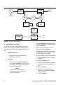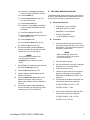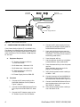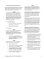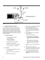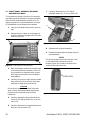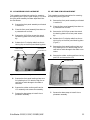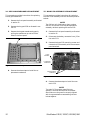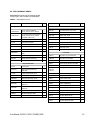
1
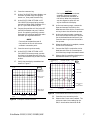
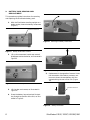
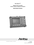
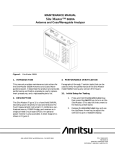
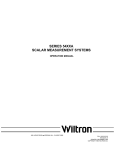
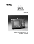
MAINTENANCE MANUAL
Site Master™ Models S113C, S331C and S115BQ
Antenna and Cable Analyzers
Figure 1.
1.
Site Master Model S331C
INTRODUCTION
This manual provides maintenance instructions for
the Site Master S113C/S331C and S115BQ Antenna
and Cable Analyzer. It describes the product and
provides performance verification procedures, parts
replacement procedures, and a replaceable parts list.
3.
Paragraphs 4 through 9 contain tests that can be
used to verify the performance of the Site Master
models S113C/ S331C and S115BQ having any version of firmware.
3.1.
2.
PERFORMANCE VERIFICATION
Initial Setup for Testing
DESCRIPTION
The Site Master (Figure 1) is a hand held SWR/RL
(standing wave ratio/return loss), and Distance-To-Fault measurement instrument. It combines a synthesized source, VSWR Bridge, and receiver on a single printed circuit board (PCB). An
optional power monitor is also available. A block diagram is shown in Figure 2.
490 JARVIS DRIVE · MORGAN HILL, CA 95037-2809
1.
Press and hold the ESCAPE/CLEAR key,
then press the ON/OFF key to turn on the
Site Master. (This sets the instrument to
the factory preset state.)
2.
Release the ESCAPE/CLEAR key and use
the Up/Down arrow key to adjust the
contrast to give a readable display.
P/N: 10580-00062
REVISION A
PRINTED: FEBRUARY 2002
COPYRIGHT 2002 ANRITSU CO.
C o u p le r
D iv id e r /
M u ltip lie r
R F
S o u rc e
x
T e s t
P o rt
x
L O
S D
S D
A D C
D is p la y
Figure 2.
4.
The following test can be used to verify the CW frequency accuracy of the Site Master. Measurement
calibration of the Site Master is not required for this
test.
2.
Press the FREQ/DIST key, then press the
F1 soft key and set F1 to 1000 MHz, then
press the ENTER key.
3.
Press the F2 soft key, set F2 to 1000
MHz, then press the ENTER key.
4.
Connect the RF cable from the Site Master Reflection Test Port to the RF Input
on the MS2663C or equivalent.
5.
Set up the Spectrum Analyzer as follows:
Equipment Required:
· Spectrum Analyzer Anritsu Model
MS2663C or equivalent
b.
S e r ia l
P o rt
Site Master Block Diagram
FREQUENCY ACCURACY
a.
C P U
Procedure:
(a) Press the Preset key, then select Preset All (F1).
(b) Press the Frequency key.
1.
Press and hold the ESCAPE/CLEAR key,
then press the ON/OFF key to turn on the
Site Master. (This sets the instrument to
the factory preset state.)
NOTE
Before continuing, allow a five
minute warm up for the internal
circuitry to stabilize.
2
(c) Press the 1 key and then the GHz key
to change the Center Frequency to 1
GHz.
(d) Press the Span key.
(e) Press the 7, 5, 0, and kHz keys sequentially to change the Frequency
Span to 750 kHz.
(f) Press the RBW key.
Site Master S113C/S331C/S115BQ MM
(g) Press the 1, 0 and kHz keys sequentially to change the RBW to 10 kHz.
5.
(h) Press the VBW key.
The following test can be used to verify the accuracy
of return loss measurements. Measurement calibration of the Site Master is required for this test.
(i) Press the Filter Off soft key (F3) to
turn the VB filter off.
(j) Press the Amplitude key.
RETURN LOSS VERIFICATION
a.
Equipment Required:
· 20 dB offset, Anritsu SC5270
(k) Press the 1, 0, and dBm keys sequentially to change the Reference Level
to 10 dBm.
· 6 dB offset, Anritsu SC5237
· Open/Short, Anritsu 22N50
(l) Press the Log Scale soft key (F5)
· 50 Ohm Termination,
Anritsu 28N50-2 or SM/PL
(m) Select 2 dB/Div (F3) and the press the
return soft key (F6).
(n) Press the Marker key.
(o) Press the Zone Width soft key (F5).
(p) Select the Spot soft key (F1).
6.
7.
On the Spectrum Analyzer, press the A, B
and then the Storage key (F5).
8.
Press the Max Hold soft key (F2).
9.
A peak response should appear on the
Spectrum Analyzer.
11.
Procedure:
1.
On the Site Master, press the SYS key,
the OPTIONS soft key and then the FIXED
CW soft key to turn Fixed CW on.
NOTE:
If the Site Master has gone into
the hold mode, press the
RUN/HOLD key to return to normal
mode.
10.
b.
Press the Marker Peak Search key on the
Spectrum Analyzer. Verify that the
marker peak readout value is 1000 MHz
±75 kHz.
Press and hold the ESCAPE/CLEAR key,
then press the ON/OFF key to turn on the
Site Master. (This sets the instrument to
the factory preset state.)
NOTE
Before continuing, allow a five
minute warm up for the internal
circuitry to stabilize.
2.
Press the MODE soft key.
3.
Use the Up/Down Arrow key to highlight
RETURN LOSS, then press ENTER.
4.
Press the START CAL key.
5.
Follow the instructions on the screen to
perform a calibration using a 22N50
Open/Short and 28N50-2 or SM/PL Termination.
6.
Connect the 20 dB offset to the Refl Test
Port and verify that the reading is:
q S113C/S115BQ: 20 dB ± 1.7 dB
On the Site Master, press the SYS key,
the OPTIONS soft key and then the FIXED
CW soft key to turn Fixed CW Off.
q S331C: 20 dB ± 1.7 dB
7.
Connect the 6 dB offset to the Refl Test
Port and verify that the reading is:
q S113C/S115BQ: 6 dB ± 1.2 dB
q S331C: 6 dB ± 1.2 dB.
Site Master S113C/S331C/S115BQ MM
3
Attenuators
560-7N50B
RF Detector
MA2418A Reference Source
50 MHz, 50 W
0dBm
15-24V DC
20 mA
MA2418A
Reference Source
Site Master S331C
1
2
START
CAL
AUTO
SCALE
SAVE
SETUP
RECALL
SETUP
3
5
LIMIT
7
SAVE
DISPLAY
9
ON
OFF
MODE
FREQ/DIST
AMPLITUDE
ESCAPE
CLEAR
4
6
DC Power Supply 2000-933
MARKER
8
RECALL
DISPLAY
0
ENTER
RUN
HOLD
+/-
PRINT
.
SYS
SWEEP
Site Master w/ Option 5 Installed
Figure 3.
6.
Power Monitor Verification
4.
Connect the DC power supply to the appropriate line voltage to supply power to
the MA2418A Reference Source.
5.
Press and hold the ESCAPE/CLEAR key,
then press the ON/OFF key to turn on the
Site Master. (This sets the instrument to
the factory preset state.)
6.
Press the MODE soft key.
· RF Detector, 10 MHz to 20 GHz,
Anritsu 560-7N50C
7.
Use the Up/Down Arrow key to highlight
POWER MONITOR, then press ENTER.
· 10 dB Attenuator, Weinschel 1-10
8.
Press the ZERO soft key to zero the power
monitor.
When complete, ZERO ADJ:ON is displayed in the message area.
9.
Verify that the power monitor reading is
0.0 dBm ± 1 dB.
10.
Connect the output of the MA2418A Reference Source to the two attenuators so
as to add 40 dB of attenuation (Figure 3).
POWER MONITOR VERIFICATION
If the Power Monitor (Option 5) is installed in the
Site Master, the following test can be used to verify
the accuracy of the power measurements. Measurement calibration of the Site Master is not required
for this test.
a.
Equipment Required:
· 30 dB Attenuator, Weinschel 1-30
· RF Reference Source, 0.050 GHz,
Anritsu MA2418A
· DC Power Supply, Anritsu 2000-933
b.
4
Procedure
1.
Connect the DC power supply to the
MA2418A Reference Source. (Refer to
Figure 3, page 4.)
11.
Connect the MA2418A Reference Source
and the attenuators to the input of the
560-7N50C RF detector.
2.
Connect the MA2418A Reference Source
to the input of the 560-7N50C RF detector.
12.
Verify that the power monitor reading is
now –40.0 dBm ±2 dB.
3.
Connect the RF Detector output to the
RF Detector input of the Site Master.
Site Master S113C/S331C/S115BQ MM
7.
INSTACAL MODULE VERIFICATION
This test verifies the performance of the Anritsu Site
Master InstaCal Calibration Module. The InstaCal
Module, part number ICN50, is an optional accessory for the S113C, S331C, and S115BQ.
NOTE
Full verification of the InstaCal module over
its entire frequency range (2 - 4000 MHz) requires both an S113C (or S115BQ) and an
S331C Site Master. However, limited verification is possible with either instrument for the
frequency range of that instrument only. The
frequency range of the S113C and S115BQ is 2
to 1600 MHz. The frequency range of the
S331C is 25 to 4000 MHz.
a.
Equipment Required:
· InstaCal Module, part number ICN50
· 20 dB offset, Anritsu SC5270
· 6 dB offset, Anritsu SC5237
b.
Procedure
NOTE
If performing full verification over the entire
frequency range with both an S113C (or
S115BQ) and an S331C Site Master, perform
this procedure first on the S113C (or S115BQ)
and then on the S331C.
1.
Press and hold the ESCAPE/CLEAR key,
then press the ON/OFF key to turn on the
Site Master. (This sets the instrument to
the factory preset state.)
NOTE
Before continuing, allow a five minute warm
up for the internal circuitry to stabilize.
2.
Press the MODE soft key.
3.
Use the Up/Down Arrow key to highlight
RETURN LOSS, then press ENTER.
4.
Press the START CAL key. The message
“CONNECT OPEN or InstaCal TO RF
Out PORT” will appear in the display.
5.
Connect the InstaCal module to the RF
Out port and press the ENTER key.
Site Master S113C/S331C/S115BQ MM
NOTE
If this particular InstaCal module has been
used to calibrate this Site Master before, the
Site Master senses the familiar InstaCal module and automatically calibrates the unit using the OSL procedure.
If the Site Master senses that the characterization data for the InstaCal module connected
to this Site Master is different than the one
currently stored, it will display soft key options to keep or replace the InstaCal characterization data.
Selecting the YES soft key transfers all of the
characterization data from this InstaCal module to the Site Master. The transfer may take
up to three minutes. This option is preferred if
this InstaCal module is to stay with this particular Site Master. Once completed, the data
will not need to be transfered again for this
combination of Site Master and InstaCal module.
Selecting the NO soft key will temporarily
transfer only the portion of the characterization data necessary for this particular calibration. This transfer takes aproximately 30 to 60
seconds, and will have to be repeated every
time a calibration is done using this combination of Site Master and InstaCal module.
6.
Verify that the calibration has been properly performed by checking that the CAL
ON! message is displayed in the upper
left corner of the display.
7.
Remove the InstaCal module from the
RF Out port and connect the 20 dB Offset to the RF Out port.
8.
Measure the return loss of the 20 dB Offset. The level should be 20 dB, ±2 dB
across the calibrated frequency range.
9.
Remove the 20 dB Offset from the RF
Out port and connect the 6 dB Offset to
the RF Out port.
10.
Measure the return loss of the 6 dB Offset. The level should be 6 dB, ±1.2 dB
across the calibrated frequency range.
5
Open/Short
50 Ohm
Termination
Termination
under Test
541XXA Scalar Measurement System
Beadless
End
Precision
Air Line
Connect Dashed Line Connections
When Directed By Procedure
A
B
Source
Adapter
Figure 4.
8.
541XXA Precision Return Loss Setup
TERMINATION VERIFICATION
This test verifies the accuracy of the Site Master
SM/PL termination using the precision return loss
mode of the 541XXA Scalar Measurement System.
Measurements of terminations using this mode provide results that are traceable to the NIST (National
Institute of Standards and Technology) standards for
the precision airline.
a.
Offset SWR
Autotester
4.
Using the Menu up-down keys: Highlight
RESET, then press the Select key.
5.
At the RESET MENU display, use the
Menu up-down keys to highlight RESET
TO FACTORY DEFAULTS, then press the
Select key.
6.
Set the signal source for the frequency
range as follows:
(a) Press the Frequency key.
Equipment Required:
(b) Using the Data Entry Keypad or
Data Entry Knob, set the Start frequency to 0.01 GHz. Press the Enter
key.
· Scalar Measurement System,
Anritsu 541XXA
· Offset SWR Autotester,
Anritsu 560-97A50-20
(c) Using the Data Entry Keypad or
Data Entry Knob, set the Stop frequency to 4.0 GHz. Press the Enter
key.
· Precision Airline, Anritsu 18N50
· Open/Short, Anritsu 22N50
· 50 Ohm Termination, Anritsu 28N50-2
7.
Press the Channel 2 Display On/Off key
to Off.
8.
Press the Channel 1 Menu key.
9.
Using the Menu up-down keys: Highlight
PRECISION RL, then press the Select key.
· Source Adapter, Anritsu 34NN50A
b.
Procedure
1.
6
Connect the test equipment as shown in
Figure 4, page 6.
2.
Press the Power key on the 541XXA to
On.
3.
Press the System Menu key.
10.
At the PRECISION RETURN LOSS
menu display, use the Menu up-down
keys to highlight FINAL, then press the
Select key.
Site Master S113C/S331C/S115BQ MM
11.
Press the Calibration key.
12.
At the CALIBRATION menu display, use
the Menu up-down keys to highlight
START CAL, then press the Select key.
13.
At the PRECISION RETURN LOSS
CALIBRATION menu display prompt,
connect the Offset SWR Autotester to Input A, if you have not done so yet.
14.
CAUTION
During both calibration and measurement, be sure to properly
align the bead-less connector of
the airline. When the connectors
are mis-aligned, a spike will usually be visible on the display.
Connect the precision air line to the Offset SWR Autotester test port. Position
the air line pointing vertically upward.
Downward or horizontal positions make
connector pin alignment difficult.
NOTE
Ensure that the bead-less end of
the precision airline is at the measurement connection point.
18.
At the next menu prompt, remove the
Open and connect the Short to the
bead-less end of the airline. Press the Select key to start the calibration process.
19.
At the next menu prompt, remove the
Short and connect the 50 Ohm Termination to the bead-less end of the air line.
Press the Select key to start the calibration process.
20.
When the calibration is complete, remove
the 50 Ohm Termination.
15.
Press the Select key when ready.
21.
16.
At the PRECISION RETURN LOSS
CALIBRATION menu prompt, connect
the Open to the bead-less end of the airline. Press the Select key to start the calibration.
Connect the SM/PL termination to the
bead-less end of the air line and press
the Select key to begin the measurement.
22.
Observe that the waveform displayed resembles that shown in Figure 6.
17.
Verify that the display resembles that
shown in Figure 5.
1 : P R E C S N R L (A )
2 : O F F
1 0 .0 d B /D IV
O F F S E T
+ 0 .0 d B
1 : P R E C S N R L (A )
2 : O F F
1 0 .0 d B /D IV
O F F S E T
+ 0 .0 d B
C U R S O R
5 4 1 4 7 A
1 : -4 6 .0 2 d B
P R E C IS IO N
R E T U R N L O S S
C A L IB R A T IO N
5 4 1 4 7 A
2 .4 0 5 0 G H z
C O N N E C T O P E N
T O A IR L IN E
P R E S S S E L E C T
F O R
C U R S O R M E N U
S T A R T : 0 .0 1 0 0 G H z
P R E S S S E L E C T
W H E N R E A D Y
S T A R T : 0 .0 1 0 0 G H z
4 0 1 p ts
Figure 5.
0 .4 G H z /D IV
S T O P : 4 .0 0 0 0 G H z
L E V E L + 7 .0 d B m
Example of a Good Connection
Site Master S113C/S331C/S115BQ MM
4 0 1 p ts
Figure 6.
0 .4 G H z /D IV
S T O P : 4 .0 0 0 0 G H z
L E V E L + 7 .0 d B m
Direct Readout of the Precision Return Loss
23.
Press the Cursor On/Off key to On.
24.
Observe the Cursor menu readout. The
minimum return loss reading for the
SM/PL termination should be 42 dB.
7
9.
BATTERY PACK REMOVAL AND
REPLACEMENT
This procedure provides instructions for removing
and replacing the Site Master battery pack.
1.
With the Site Master standing upright on a
stable surface, locate the battery access door
(Figure 7).
BATTERY ACCESS DOOR
Figure 9.
Figure 7.
2.
Battery Access Door Location
Lift up the access door handle and rotate it
90 degrees counterclockwise, as illustrated in
Figure 8.
Figure 10.
5.
Figure 8.
Removing the Battery
Replacement is the opposite of removal. Note
the orientation of the battery contacts, and
be sure to insert the new battery with the
contacts facing the rear of the unit (Figure
10).
Rotate the Battery Access Door Handle
3.
Lift the door and remove, as illustrated in
Figure 11.
4.
Grasp the battery lanyard and pull the battery straight up and out of the unit, as illustrated in Figure 9.
BATTERY CONTACTS
Figure 11.
8
Removing the Battery Access Door
Battery Orientation
Site Master S113C/S331C/S115BQ MM
10. BATTERY INFORMATION
The following information relates to the care and
handling of the Site Master battery, and NiMH batteries in general.
· The Nickel Metal Hydride (NiMH) battery supplied with the Site Master is shipped in a discharged state. Before using the Site Master, the
internal battery must first be charged for three
hours, either in the Site Master or in the optional battery charger (Anritsu part number:
2000-1029).
· Use only Anritsu approved battery packs.
· Batteries must be recycled or disposed of properly. Do not place batteries in household garbage.
· Always use the battery for its intended purpose
only.
10.1.
Battery Testing Procedure
1.
2.
· Recharge the battery only in the Site Master or
in an Anritsu approved charger.
· With a new NiMH battery, full performance is
achieved after three to five complete charge and
discharge cycles.
Disconnect the AC-DC Adapter when the
Battery Charging LED turns off, indicating
the battery is fully charged.
3.
Press and hold the ESCAPE/CLEAR key,
then press the ON/OFF key to turn on the
Site Master. This sets the instrument to
the factory preset state. Press ENTER
when prompted to continue.
4.
Press the SYS key, followed by the
STATUS soft key. Verify that the indicated
battery charge is ³ 80%. If the value is
80% or above, press the ESCAPE/CLEAR
key and continue with this procedure.
· When the Site Master or the charger is not in
use, disconnect it from the power source.
· Do not charge batteries for longer than 24
hours; overcharging may shorten battery life.
With the Site Master off and the battery
installed, connect the Universal AC
Adapter to the 12.5-15VDC (1100 mA) connector. The External Power LED and the
Battery Charging LED will light.
· If left unused a fully charged battery will discharge itself over time.
· Temperature extremes will affect the ability of
the battery to charge: allow the battery to cool
down or warm up as necessary before use or
charging.
If the value is lower than 80%, a discharge/charge cycle may be needed to improve the battery capacity. Completely
discharge the battery, as described in
Steps 5 and 6 below, and then recharge
the battery as described in Steps 1 and 2.
If the battery capacity does not increase
after a discharge/charge cycle, replace
the battery.
· Discharge an NiMH battery from time to time
to improve battery performance and battery life.
· The battery can be charged and discharged
hundreds of times, but it will eventually wear
out.
· The battery may need to be replaced when the
operating time between charging becomes noticeably shorter than normal.
5.
Press the START CAL key (to keep the
Site Master from going into HOLD mode)
and make note of the test start time.
· Never use a damaged or worn out charger or
battery.
6.
When the Site Master display fades and
the Site Master switches itself off, make
note of the test stop time.
7.
The total test time (Step 5 to Step 6)
should be ³ 2.5 hours. If the total test
time is <2.5 hours, replace the battery.
· Storing the battery in extreme hot or cold places
will reduce the capacity and lifetime of the battery.
· Never short-circuit the battery terminals.
· Do not drop, mutilate or attempt to disassemble
the battery.
· Do not dispose of batteries in a fire!
Site Master S113C/S331C/S115BQ MM
9
11. FRONT PANEL ASSEMBLY REMOVAL
AND REPLACEMENT
7.
Carefully disconnect the LCD display
backlight cable from J15 on the main PCB.
This procedure provides instructions for removing
and replacing the Site Master front panel assembly.
With the front panel assembly removed, the LCD
display, keypad PCB, keypad membrane, and main
PCB assemblies can be removed and replaced.
J15
J4
1.
Place the Site Master face up on a work surface.
2.
Remove the four rubber corner bumpers by
carefully sliding the bumpers off of the case
corners (Figure 15).
J12
Figure 13.
Figure 12.
3.
4.
Removing the Corner Bumpers
8.
Remove the front panel assembly.
9.
Reverse the above steps to replace the front
panel assembly.
NOTE
The corner bumpers only mount one way. That
is, the raised area inside one end of the
bumper (Figure 13) is made to conform to the
contour of the front cover only.
With the bumpers removed, the access holes
for the case screws are revealed. Use a Phillips screwdriver to remove the four screws
securing the two halves of the Site Master
case together.
RAISED AREA
Carefully lift up on the right side (as viewed
from the front) of the front half of the case
and begin to separate the two halves.
CAUTION
Do not force or pull the two halves of the case
apart as there are delicate cables attached between the two halves that must be disconnected first.
10
Corner Bumper Detail
5.
Carefully depress the latch tab and disconnect the LCD display cable from J12 on the
main PCB.
6.
Carefully disconnect the keypad interface cable from J4 on the main PCB.
Figure 14.
Site Master Front Panel Cable Connections
Site Master S113C/S331C/S115BQ MM
12. LCD ASSEMBLY REPLACEMENT
13. KEY PAD PCB REPLACEMENT
This procedure provides instructions for removing
and replacing the Liquid Crystal Display (LCD) once
the front panel assembly has been separated from
the Site Master.
This procedure provides instructions for removing
and replacing the key pad PCB.
1.
2.
3.
4.
1.
Remove the front panel assembly as directed
in section 11.
Remove the front panel assembly as directed
in section 11.
2.
Place the front panel assembly face down on
a protected work surface.
Place the front panel assembly face down on
a protected work surface.
3.
Remove the 14 Phillips screws that attach
the backing plate to the front panel assembly.
Remove the 14 Phillips screws that attach
the backing plate to the front panel assembly.
4.
Release the LCD display cable from the retaining clip on the front panel backing plate
(Figure ).
5.
Remove the front panel backing plate, carefully feeding the LCD cable through the access hole to avoid damage to the cable or connector.
6.
Remove the rubber cushion pad from the key
pad PCB and remove the PCB.
Release the LCD display cable from the retaining clip on the front panel backing plate.
FRONT PANEL
BACKING PLATE
LCD CABLE
RETAINING CLIP
KEYPAD PCB
Figure 15.
Front Panel Backing Plate
5.
Remove the front panel backing plate, carefully feeding the LCD cable through the access hole to avoid damage to the cable or
connector.
6.
Remove the rubber cushion pad from the
LCD assembly and remove the assembly.
7.
Reverse the above steps to install the replacement assembly.
Site Master S113C/S331C/S115BQ MM
Figure 16.
7.
Front Panel Keypad PCB Location
Reverse the above steps to install the replacement assembly.
11
14. KEY PAD MEMBRANE REPLACEMENT
15. MAIN PCB ASSEMBLY REPLACEMENT
This procedure provides instructions for replacing
the key pad membrane.
This procedure provides instructions for replacing
the main PCB assembly with the connector panel attached.
1.
Remove the front panel assembly as directed
in section 11.
2.
Remove the key pad PCB as directed in section 13.
3.
Remove the keypad membrane by gently
pulling the membrane up and out of the
holes in the front panel.
NOTE
The lithium-coin clock battery (part number
633-26) on the main PCB may be replaced as
necessary without replacing the entire PCB.
1.
Remove the front panel assembly as directed
in section 11.
2.
Disconnect the battery connector from J13 on
the main PCB.
3.
Remove the three PCB mounting screws and
remove the PCB assembly with the connector
panel attached.
KEYPAD MEMBRANE
CLOCK
BATTERY
J13 BATTERY
ONNECTOR
Figure 17.
4.
Front Panel Keypad Membrane
Reverse the above steps to install the replacement membrane.
PCB MOUNTING
SCREWS (3)
Figure 18.
4.
Main PCB
Reverse the above steps to install the new
main PCB.
NOTE
The main PCB connector panel fits into
grooves in the two halves of the Site Master
case. Make sure the panel is correctly aligned
with the grooves before reassembling the two
halves together.
12
Site Master S113C/S331C/S115BQ MM
16. REPLACEABLE PARTS
Replaceable parts for the Site Master Model
S113C/S331C and S115BQ are listed below.
Table 1.
Replaceable Parts List
Part Number
Description
Qty
Part Number
Description
Qty
Hardware
Accessories
900-861
Pan Head Screw, 4-20, 0.365
15
900-869
Screw, 4-40, 0.875
4
900-720
Screw, 4-40, 0.187
3
900-697
Screw, 4-40, 0.312
3
1
785-929
M-F Stand off, 4-40, 11/16
3
Universal AC Adapter
1
900-326
Kep Nut, 4-40, 0.187
8
2000-1029
Battery Charger
1
790-516
Hole Plug, 0.6875L
1
22N50
Precision Short/Open, N Male
1
790-42
Hole Plug, 0.625
1
SM/PL
Precision RF Terminator, N Male
1
761-79
Cap Vinyl, Black, round
1
OSLN50LF
Precision Open/Short/Load, N
Male
1
806-62
Cable Assy, Cig Plug, Female
1
46652-1
Top Case only, S113C/S331C
1
800-441
Serial Interface Cable Assy
1
46652-2
Top Case only, S115BQ
1
48258
Soft Carrying Case
1
46653-1
Bottom Case only
1
48297
Plastic Display Window, S115BQ
1
48231-1
Battery Door
1
Battery Door Latch (3 pieces)
10580-00060
User's Guide, Site Master
S113C, S114C, S331C, S332C
1
10580-00061
Programming Manual, Site Master
S113C, S114C, S331C, S332C
(available on disk only)
1
2300-347
Software Tools CD, Site Master
40-115
Replaceable Parts
Case Parts
510-87
N-Connector
1
ND57371
Option 05 Input Connector
with cable
1
790-509
790-510
790-511
15-102
Liquid Crystal Display Assy
1
46655
Case Corner Bumpers
4
633-27
Rechargeable Battery, NiMH
1
46662
LCD Retainer Plate
1
ND57959
Main PCB Assembly, S113C
1
48241
Foam, LCD Corners
8
ND57963
Main PCB Assembly, S331C
1
48278
Foam, LCD Window
1
ND57960
Main PCB Assembly, S113C with
Option 05
1
46659
Foam, LCD Backing
1
46661
Foam, Keypad Backing
1
ND57964
Main PCB Assembly, S331C with
Option 05
1
48246
Foam, Battery Door
4
47812-3
Keypad PCB Assy
1
720-19
Cable Clamp
1
46649-1
Membrane Keypad, Main
1
790-515
Spring, Battery Compartment
3
633-26
Lithium Coin Clock Battery
1
55216
ID Label, Model S113C
1
55223
ID Label, Model S331C
1
55224
ID Label, Model S115BQ
1
Site Master S113C/S331C/S115BQ MM
1
13
NOTES
Table 2.
Anritsu Service Centers
UNITED STATES
FRANCE
SINGAPORE
ANRITSU COMPANY
685 Jarvis Drive
Morgan Hill, CA 95037-2809
Telephone: (408) 776-8300
FAX: 408-776-1744
ANRITSU S.A
9 Avenue du Quebec
Zone de Courtaboeuf
91951 Les Ulis Cedex
Telephone: 016-09-21-550
FAX: 016-44-61-065
ANRITSU (SINGAPORE) PTE LTD
10, Hoe Chiang Road
#07-01/02
Keppel Towers
Singapore 089315
Tel:65-282-2400
Fax:65-282-2533
ANRITSU COMPANY
10 NewMaple Ave., Unit 305
Pine Brook, NJ 07058
Telephone: (201) 227-8999
FAX: 201-575-0092
ANRITSU COMPANY
1155 E. Collins Blvd
Richardson, TX 75081
Telephone: 1-800-ANRITSU
FAX: 972-671-1877
AUSTRALIA
ANRITSU PTY. LTD.
Unit 3, 170 Foster Road
Mt Waverley, VIC 3149
Australia
Telephone: 03-9558-8177
FAX: 03-9558-8255
BRAZIL
ANRITSU ELECTRONICA LTDA.
Praia de Botafogo 440. Sala 2401
CEP22250-040,Rio de Janeiro,RJ, Brasil
Telephone: 021-527-6922
Fax: 021-53-71-456
CANADA
ANRITSU INSTRUMENTS LTD.
215 Stafford Road, Unit 102
Nepean, Ontario K2H 9C1
Telephone: (613) 828-4090
FAX: (613) 828-5400
CHINA (SHANGHAI)
ANRITSU ELECTRONICS CO LTD
2F,Rm.B, 52 Section Factory Bldg.
NO 516 Fu Te Road (N)
Waigaoqiao Free Trade Zone
Pudong, Shanghai 200131
PR CHINA
Telephone: 86-21-58680226
FAX: 86-21-58680588
GERMANY
ANRITSU GmbH
Grafenberger Allee 54-56
D-40237 Dusseldorf
Germany
Telephone: 0211-968550
FAX: 0211-9685555
SOUTH AFRICA
ETESCSA
12 Surrey Square Office Park
330 Surrey Avenue
Ferndale, Randburt, 2194
South Africa
Telephone: 011-27-11-787-7200
Fax: 011-27-11-787-0446
INDIA
MEERA AGENCIES (P) LTD
A-23 Hauz Khas
New Delhi, India 110 016
Telephone: 011-685-3959
FAX: 011-686-6720
ISRAEL
TECH-CENT, LTD
4 Raul Valenberg St.
Tel-Aviv, Israel 69719
Telephone: 972-36-478563
FAX: 972-36-478334
ITALY
ANRITSU Sp.A
Rome Office
Via E. Vittorini, 129
00144 Roma EUR
Telephone: (06) 50-2299-711
FAX: 06-50-22-4252
JAPAN
ANRITSU CUSTOMER SERVICE LTD.
1800 Onna Atsugi—shi
Kanagawa-Prf. 243 Japan
Telephone: 0462-96-6688
FAX: 0462-25-8379
KOREA
ANRITSU SERVICE CENTER
8F Sanwon Bldg.
1329-8 Seocho-Dong
Seocho-Ku
Seoul, Korea 137-070
Telephone: 82-2-581-6603
FAX: 82-2-582-6603
SWEDEN
ANRITSU AB
Botvid Center
Fittja Backe 13A
145 84
Stockholm, Sweden
Telephone: (08) 534-707-00
FAX: (08)534-707-30
TAIWAN
ANRITSU CO., LTD.
6F, No. 96, Section 3
Chien Kuo N. Road
Taipei, Taiwan, R.O.C.
Telephone: (02) 515-6050
FAX: (02) 509-5519
UNITED KINGDOM
ANRITSU LTD.
200 Capability Green
Luton, Bedfordshire
LU1 3LU, England
Telephone: 015-82-43-3200
FAX: 015-82-73-1303