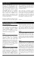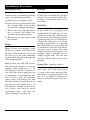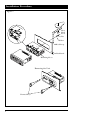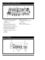
1
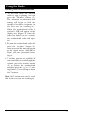
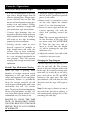
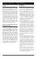
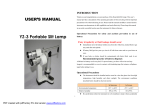
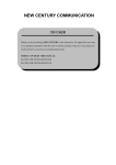
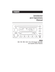
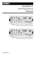
R
Installation
and Operations
Manual
M9850 High Power (35 Watts x 4) AM/FM/WB Stereo
Receiver and Auto Reverse Cassette Deck
M9860 High Power (40 Watts x 4) AM/FM/WB Stereo
Receiver and Auto Reverse Cassette Deck
© Copyright 1998
Magnadyne Corporation
Introduction
Your new AM/FM/WB cassette unit
incorporates a microcomputer managed electronic AM/FM stereo tuning system and FM Optimizer along
with rugged auto reverse cassette
mechanism. The two as a combination will provide the user with the
finest crystal clear AM/FM stereo
radio broadcast reproduction and
flawless reproduction of your personal cassette tape library.
To insure trouble free long term performance from your new unit, please
take a moment to read this manual
completely to make yourself aware of
all basic radio operation and memory
setting procedures.
Also at this time, it would be a good
idea to write down the serial number
of the unit in the space provided. In
the unlikely event that the radio will
need warranty service, you will need
this number to obtain the service.
Serial # ________________________
Mechanical Installation
Space Requirements:
To mount your new AM/FM cassette
unit, you will need a rectangle hole in
the mounting location 182mm
(width) x 53mm (height), (7⁄8” x 2 1⁄8”)
and a full 6” of unobstructed space
behind the mounting location.
Step 1:
After obtaining the required space
and mounting hole dimensions
required, remove the mounting
sleeve from the unit. Insert the
mounting sleeve into the hole on the
dashboard. Secure it by bending the
tabs inward as shown in fig 1. Select
the appropriate tab according to the
thickness of the dashboard.
Step 2:
Bring the power, ground, antenna
and speaker wires through the center
of the mounting sleeve. Make all the
speaker and power connections to
the main harness supplied with the
unit. Refer to the “wiring” section of
2
this unit for proper connection. After
all the connections have been made
and are correct, plug the harness and
the antenna cable into the mating
plugs located on the rear of the unit.
Step 3:
Turn on the ignition key and do a
pre-installation check of all the functions with the unit out of the dashboard to make sure that everything is
operating properly before final installation.
Step 4:
Securely attach the rear support strap
provided to the rear of the unit with
the fasteners provided. Bend the
strap to allow the unit to slide into it’s
mounting sleeve. Reach up behind
the unit and grab the strap while sliding the unit into the mounting sleeve
until it snaps into place. Secure the
end of the strap to a solid portion of
the dashboard structure or the fire
wall.
Installation Procedure
Removing the Unit:
Red Wire:
In the event that the unit requires
removal from it’s mounting location,
repeat the following procedures.
Connect the red wire to a source of
12 volts that is controlled by the ignition key. Use a test light or volt meter
to locate a connection point at the
fuse block.
A. Release the rear support strap.
B. Insert the keys provided into the
slot on both sides of the chassis
until locked. (snapped into place)
C. Pull on the keys with equal pressure to release and remove the
unit from the mounting sleeve.
D. Disconnect the wire harness and
the antenna.
Wiring:
Note 1: If you are installing a completely new system, install all of the
speakers and antenna first, then run
the wires up to the radio mounting
location and bring them through the
radio mounting hole.
Note 2: Your new AM/ FM cassette
unit has been designed to operate
properly when connected to a “12
Volt Negative Ground” electrical system. Any other power supply may not
be acceptable. Connecting your new
unit to other than the specified
power source will damage the unit
and will void the warranty. If you are
not sure that your vehicle uses a “12
Volt Negative Ground” electrical system, contact your local car stereo
installation center and find out
before making any connections.
Black Wire:
Connect the black wire to the frame
of the vehicle. It is strongly recommended that the black wire be connected to a part of the vehicles frame,
floorboard or sub structure to insure
a good ground. It is Not advisable to
connect the black wire to a factory
provided ground wire. It is possible
that many other electrical items will
be connected to this wire and electrical noises such as pops and clicks
could be present in your speakers. In
addition, shared grounds tend to
amplify engine noise into the unit
and you will hear the noise in your
speakers.
Orange Wire: (with fuse holder)
Connect the orange wire to a constant source of 12 volts. The battery
(+) post or the battery portion of the
fuse block is a good location for this
wire. Use a test light or volt meter to
locate a connection point at the fuse
block.
3
Installation Procedure
Figure 1
Sheet
Metal
Screw
Nut
Washer
Metal Strap
Dashboard
VO
PW L
R
BA
PU L
LL
BA
SS
FA
D
TR
EB
LE
TU
NE
Mounting Sleeve
SC
AN
BA
ND
1
R.
2
AU40w
TO
AM
FR
EQ
3
WE
AT
HE
R
x
RE4 HI
/ FMVE GH
RS PO
/W E W
B CA ER
ST SS
ER ET
EO TE
4
5
40
w
x4
W
EA
TH
ER
BA
ND
Removing the Unit
Removal Keys
4
Installation Procedure
Speaker Connections:
Wiring Two Speakers:
Note: Every speaker has a positive (+)
and a negative (-) connection terminal, therefore every speaker must
have two wires connected to it. To
properly connect the speaker system
to your new AM/FM cassette unit,
you must have a + and - wire coming
from every speaker to connect to the
unit.
Green Wire:
Connect the Green wire to the Left
speaker “Positive” wire.
If you are connecting 2 speakers, you
should have 4 wires to connect. If you
are connecting 4 speakers, you
should have 8 wires to connect.
Wiring Four Speakers:
(Fader Control Operational)
Green Wire:
Connect the Green wire to the Left
Front speaker “Positive” wire.
Green/Black Wire:
Connect the Green/Black wire to
the Left speaker “Negative” wire.
Gray Wire:
Connect the Gray wire to Right
speaker “Positive” wire.
Gray/Black Wire:
Connect the Gray/Black wire to the
Right speaker “Negative” wire.
Warning !
1. Do Not Ground any speakers to the
frame of the vehicle or to any
other grounding system.
Green/Red Wire:
Connect the Green/Red wire to the
Left Rear speaker “Positive” wire.
2. The fader control used in the
M9850/M9860 radio can not be
deleted. When connecting two
speakers to the unit, use only the
front set of wires provided in the
harness. Insulate the remaining
rear speaker wires provided in the
harness. (Tape the wires)
Black/Green Wire:
Connect the Black/Green wire to the
Left Rear speaker “Negative” wire.
3. Do Not Connect the left front and
left rear wires together for any reason. This will damage the unit.
Green/Black Wire:
Connect the Green/Black wire to
Left Front speaker “Negative” wire.
Gray Wire:
Connect the Gray wire to Right
Front speaker “Positive” wire.
Gray/Black Wire:
Connect the Gray/Black wire to the
Right Front speaker “Negative” wire.
Gray/Red Wire:
Connect the Gray/Red wire to the
Right Rear speaker “Positive” wire.
Black/Gray Wire:
Connect the Black/Gray wire to the
Right Rear speaker “Negative” wire.
5
Installation Procedure
Four Speaker Wiring
9
8
7
6
5
4
3
2
1
-
+
-
Gray Wire
Green/Black Wire
Green Wire
Red Wire 12 VDC Ign./Acc. Lead
Orange Wire 12 VDC Constant
10A
-
10
+
+
11
Black Wire 12 VDC Ground
Black/Gray Wire
Gray/Red Wire
Black/Green Wire
Green/Red Wire
Gray/Black Wire
-
12
Right
Rear Speaker
+
Right
Front Speaker
Left
Rear Speaker
Left
Front Speaker
Two Speaker Wiring
Right Front Speaker
12
11
10
9
8
7
6
5
4
3
2
1
Black Wire 12 VDC Ground
Black/Gray Wire
+
-
Gray/Red Wire
Black/Green Wire
Green/Red Wire
Gray/Black Wire
Gray Wire
Tape
Ends
Green/Black Wire
Green Wire
Red Wire 12 VDC Ign./Acc. Lead
Orange Wire 12 VDC Constant
10A
+
-
Left Front Speaker
6
Control Button Identification
Figure 2
2 1
6
3
5
4 12 7
8
13
10
11
9
1. On/Off Power Switch, Balance
Control and Volume Level
Adjuster.
2. Fader Control.
3. Bass/Treble Tone Controls.
4. Radio Band Selector Button.
5. Manual Tuning Control Buttons.
6. Radio Station Scan Button.
7. Frequency Selector Button.
8. Weatherband Radio Selector
Switch.
9. Display.
10. Tape Door Slot.
11. Fast Forward and Rewind
Buttons.
12. Eject Button.
13. Preset Stations Buttons.
Radio Display
Figure 3
9
9a
9b
9c
9e
9d
7
Radio Display
Figure 4
Using the Radio
Listening to the Radio:
<
<
1. Turn the vehicle’s ignition key to
the “on” or “acc” position to provide power to the radio.
2. Rotate knob (1) clockwise to turn
the radio on. Adjust the volume
knob (1) to a low listening level.
3. Use the band button (4) to select
the AM or FM radio band. The FM
band has 3 banks (FM1, 2, and 3).
The AM band has 2 banks (AM 1
and AM 2)
4. Use the tuning button (5) to select
a desired radio station. Press the
“ “(up) button to tune to
higher radios stations.Use the “ “
(down) button to tune to lower
radio stations. Pressing and releasing the tuning control buttons (5)
will cause the tuner to move up or
down two decimal increments.
Pressing and holding the up or
down tuning buttons (5) will cause
the tuner to count up or down at
high speed.
5. If you are traveling in an area
where you are not familiar with the
local radio stations, Press and
release the scan button (6). This
will activate the auto tuning system
and the tuner will scan up to the
8
next available strong station and
stop for 5 seconds. After 5 seconds
has passed, the tuner will search up
to the next strongest station and
stop. If you find a station to your
liking, simply press and release the
scan button once again to stop the
scan operation.
6. Adjust the treble, bass, fader, balance and volume controls as needed using the information “Audio
adjustments” section of this manual.
Display Priority Note:
The priority of the display area (9) is
for the clock. 5 seconds after the last
tuning control command, the display
will change and display the clock. To
recall the radio frequency, press and
release the “R.Freq” button (7). The
display will change to show the radio
frequency then will revert back to the
clock after 5 seconds.
Using the Radio
Listening to the Weatherband Radio
1. At any time when the AM/FM
radio or tape is playing, you can
press the “Weather” button (8).
The automatic weatherband seek
tuning will begin to find the
strongest broadcast frequency in
the area you are traveling in .
When the weatherband radio is
activated, “WB” will appear in the
display area (Figure 4). Once the
tuner has locked on to a station,
the weatherband radio will operate.
2. To turn the weatherband radio off,
press the “weather” button (8)
once more and the unit will return
to the signal source (AM/FM or
Tape) you were previously listening to.
<
<
3. 7 weather stations are available. If
you would like to scroll though the
stations, press the weather button
(8) to activate the weatherband
and then press the “ “ or “ “ tuning button (5) to scroll up or down
the 7 stations.
Note: All 7 stations may not be available in the area you are traveling in.
9
Cassette Operation
Some Notes About Cassette Tapes
How to Listen to a Tape
* It is not recommended to use any
tape with a length longer than 90
minutes playing time. Longer tapes
create excessive load on the tape
motor and mechanism causing premature wear and failures. Longer
tapes have a tendency to tangle and
jam automotive tape mechanisms.
1. Turn the vehicles ignition key to
the ON or ACC position to provide
power to the radio.
2. Rotate knob (1) clockwise to turn
on the unit. Adjust the volume
knob (1) to a low listening level.
3. Insert a cassette tape into the the
cassette opening (10) with the
thick side pointing toward the
right
Note: The cassette tape will only fit
in one direction. If the tape does
not insert easily, DO NOT FORCE
IT. Turn the tape over and reinsert it. At this time the display
(9) will be showing the tape play
indicators (9e)
4. Adjust the volume, bass and treble
controls to suit your taste.
* Cassette tape housings that are
warped or that have loose indicator
labels should not be used. Doing so
will result in the tape becoming
jammed in the mechanism.
* Storing cassette tapes in areas
directly exposed to sunlight or
high temperatures will cause the
cassette cases to warp rendering
them unusable. Store cassette tapes
in a case designed specifically for
that purpose. This will prevent
warpage and foreign material contamination.
Periodic Tape Mechanism Cleaning
While the tape is playing, small
deposits of foreign material attach
themselves to the tape head, pinch
rollers and capstans of the tape player
mechanism. Failure to periodically
clean the foreign material off will
result in poor sound quality and a tape
mechanism that will “eat” cassette
tapes. To prevent this from happening,
the use of a good quality “wet type” cassette head and capstan cleaner is recommended every 10 hours of use.
FAILURE TO CLEAN THE TAPE
DECK AT REASONABLE INTERVALS WILL RESULT IN TAPE DECK
SERVICE THAT IS NOT COVERED
BY WARRANTY.
10
Changing the Tape Program
Cassette tapes have two playing sides,
side (A) and side (B). The cassette
player in this unit will play either side
of the tape. If you wish to change play
from side (A) to side (B) or vise versa,
press and release the FF and REW
buttons at the same time. The tape
play indicator (9E) will show the new
direction and the tape will begin to
play.
Note: If the tape is allowed to run to
the end of the side that is playing , it
will automatically change over to the
remining side and play.
Cassette Operation
Programming
Programming the Radio Station
Recall Buttons
The two buttons located to the right
side of the tape opening (10) are the
fast forward and rewind buttons (11).
While the tape is playing you can use
these buttons to fast advance the tape
to search for special sound tracks or
rewind the tape to listen to it from
the beginning. To operate these buttons, simply press one or the other in
until it locks. To release it, press the
opposite button slightly. The “FF”
button will always fast advance the
tape forward and the “REW” button
will always fast rewind the tape.
1. Rotate knob (1) clockwise to turn
on the unit. Adjust the volume
knob (1) to a low listening level.
2. Use the band button (4) to select
the AM or FM radio band you want
to memorize a radio station. The
FM band has 3 banks (FM 1, 2, and
3). The AM band has 2 banks (AM
1 and 2). Continue pressing the
band button (4) until the desired
radio band is displayed (9a).
3. Use the tuning button (5) to select
a desired radio station. Press the
“ ” (up) button to tune to higher
radios stations. Use the “ ” (down)
button to tune to lower radio stations. Pressing and releasing the
tuning control buttons (5) will
cause the tuner to move up or
down two decimal increments.
Pressing and holding the up or
down tuning buttons (5) will cause
the tuner to count up or down at
high speed.
4. Once the desired station is selected, press and hold down one of the
5 station recall buttons (13) until
the channel indicator (9d) is
displayed, release the button. The
station is now memorized to the
band indicated (9a) and the recall
button indicated (9d). Repeat procedures 2 thru 4 for all 5 preset
buttons.
5. Select another radio bank and
repeat steps 2 thru 4 above to
memorize all 15 FM radio stations
and 10 AM radio stations.
<
<
Using the Fast Forward and Rewind
Controls
Listing to the Radio Tuner While Fast
Advancing the Tape
To listen to the AM/FM radio while
the tape is rewinding or fast forwarding, press the “R.FREQ” button after
the FF or REW button is pushed. This
will turn on the radio tuner until the
FF or REW button is released and the
tape begins to play again. Once this
feature is turned on, each time the
“FF and “REW” buttons are pushed,
the radio tuner will come on automatically. If you want to turn this feature off, press the ‘R.FREQ” button
while the tape is fast forwarding or
rewinding. The tuner will be off.
11
Clock Settings
1. Turn the vehicles ignition key to
the ON or ACC position to provide
power to the radio. You will know
that radio has sufficient power as
the clock will be displayed in the
LCD display window (9).
2. Press the ‘R.FREQ” button (7) and
hold it down.
3. Adjust the HOURS by pressing the
“ “ (down) tuner control button
(5) until the correct hour is displayed.
Note: The clock is a 12 hour clock
and does not indicate “ AM or
PM”.
4. Adjust the MINUTES by pressing
the “ “ (up) tuner control button
(5) until the correct minutes are
displayed.
1. While the radio is on, press the
‘R.FREQ” button (7) to display the
time. Hold the button down.
2. Adjust the HOURS by pressing the
“ “ (down) tuner control button
(5) until the correct hour is
displayed.
Note: The clock is a 12 hour clock
and does not indicate “ AM or
PM”.
3. Adjust the MINUTES by pressing
the “ “ (up) tuner control button
(5) until the correct minutes are
displayed.
<
<
12
<
Setting the Clock with the Radio On
<
Setting the Clock with the Radio Off
Audio
Audio Adjustments
Volume Level
1. Rotate the volume control knob
(1) clockwise to increase the
volume.
2. Rotate the volume control knob
(1) counter clockwise to decrease
the volume.
Left to Right Balance
1. Pull the volume control knob (1)
outward until it locks.
2. Rotating the knob to the left will
balance the speakers to the left.
3. Rotating the knob to the right will
balance the speakers to the right
4. The mechanical center of the control has a “click” feel to it.
5. When the speaker balance is set as
desired, unlock the knob by pushing on it. The knob will now adjust
the volume.
Front to Rear Speaker Balance
(Fader Control)
Rotate the fader control clockwise or
counter clockwise to adjust the speaker balance from the front of the vehicle to the rear of the vehicle.
Treble Tone Control
1. Rotate the treble control (3) clockwise to increase the high tones.
2. Rotate the treble control (3)
counter clockwise to decrease the
high tones.
3. The mechanical center of the control has a “click” feel and is considered zero.
Loudness Boost
1. The loudness boost is automatic.
For the first 1/2 rotation of the volume control, the loudness circuit is
active and will boost up the low
range (100Hz) and high range
(10Khz) to compensate for the
music tones that are not normally
heard at low volume listening.
2. After the volume control is rotated
past the 1/2 way mark, the loudness effect will diminish as at these
higher volumes, the boost is not
needed.
Bass Tone Control
1. Rotate the bass control (3) clockwise to increase the bass tones.
2. Rotate the bass control (3) counter
clockwise to decrease the bass
tones.
3. The mechanical center of the control has a “click” feel and is considered flat.
13
Specifications
AM/FM Tuner
FM Frequency Range . . . . . . . . . . . . . . . . . . . . . . . . . . . . . . . . . . . . 87.5 - 107.9MHz
AM Frequency Range . . . . . . . . . . . . . . . . . . . . . . . . . . . . . . . . . . . . . 520 - 1720 KHz
IF Rejection . . . . . . . . . . . . . . . . . . . . . . . . . . . . . . . . . . . . . . . . . . . . . . . . . AM 45dB
. . . . . . . . . . . . . . . . . . . . . . . . . . . . . . . . . . . . . . . . . . . . . . . . . . . . . . . . . . . . . . .FM 70dB
Image Rejection . . . . . . . . . . . . . . . . . . . . . . . . . . . . . . . . . . . . . . . . . . . . . . AM 55dB
. . . . . . . . . . . . . . . . . . . . . . . . . . . . . . . . . . . . . . . . . . . . . . . . . . . . . . . . . . . . . . .FM 55dB
Selectivity . . . . . . . . . . . . . . . . . . . . . . . . . . . . . . . . . . . . . . . . . . . . . . . . . . . AM 30dB
. . . . . . . . . . . . . . . . . . . . . . . . . . . . . . . . . . . . . . . . . . . . . . . . . . . . . . . . . . . . . . .FM 60dB
S/N ratio (Signal to Noise) . . . . . . . . . . . . . . . . . . . . . . . . . . . . . . . . . . . . . AM 48dB
. . . . . . . . . . . . . . . . . . . . . . . . . . . . . . . . . . . . . . . . . . . . . . . . . . . . . . . . . . . . . . .FM 65dB
Stereo Separation . . . . . . . . . . . . . . . . . . . . . . . . . . . . . . . . . . . . . . . . . . . . . . . . 32dB
Cassette:
Wow & Flutter . . . . . . . . . . . . . . . . . . . . . . . . . . . . . . . . . . . Less than 0.35% WRMS
Signal to Noise . . . . . . . . . . . . . . . . . . . . . . . . . . . . . . . . . . . Ratio Better than 45dB
Frequency Response . . . . . . . . . . . . . . . . . . . . . . . . . . . . . . . . . . . . . . . 60Hz - 10kHz
General:
Power Requirements . . . . . . . . . . . . . . . . . . . . . 11.2V - 14.4V DC Negative Ground
Treble Control . . . . . . . . . . . . . . . . . . . . . . . . . . . . . . . . . . . . . . . . . ± 10dB @ 10kHz
Bass Control . . . . . . . . . . . . . . . . . . . . . . . . . . . . . . . . . . . . . . . . . . ± 10 dB @ 100Hz
Speaker Impedance Requirements
4 or 8 Ohm
Output Power:
M9850
20 Watts x 4 @ 10% THD
35 Watts x 4 Max
M9860
22 Watts x 4 @ 10% THD
40 Watts x 4 Max
Weight . . . . . . . . . . . . . . . . . . . . . . . . . . . . . . . . . . . . . . . . . . . . . . . . . . . . . . . . . . 2.5 lbs.
Features and Specifications are subject to change and improvement without notice.
14
Notes:
15
Warranty
ONE (1) YEAR LIMITED WARRANTY
Magnadyne Corporation or its authorized agents will within 1 year from the date of
sale to you, repair, replace or refund the retail sales price of said product or any part
thereof, at the option of the Magnadyne Corporation or its authorized agents, if said
product or part is found defective in materials or workmanship, when properly connected and operating on the correct power requirements designated for the specific product. This warranty and Magnadyne Corporation or its authorized agents
obligations hereunder do not apply where the product was; damaged while in the
possession of the consumer, subjected to unreasonable or unintended use, not reasonably maintained, utilized in commercial or industrial operations, or serviced by
anyone other than Magnadyne Corporation or its authorized agents, or where the
warning seal on the product is broken or the power and/or plugs are detached from
the unit. Magnadyne Corporation or any of its authorized agents will not assume any
labor costs for the removal and re-installation of any product found to be defective,
or the cost of transportation to Magnadyne Corporation or its authorized agents.
Such cost are the sole responsibility of the purchaser.
This warranty does not cover the cabinet appearance items or accessories used in
connection with this product, or any damage to recording or recording tape, or any
damage to the products resulting from improper installation, alteration, accident,
misuse, abuse or acts of nature.
MAGNADYNE CORPORATION OR ITS AUTHORIZED AGENTS SHALL NOT BE
LIABLE TO ANYONE FOR CONSEQUENTIAL OR INCIDENTAL DAMAGES OR
CLAIMS EXCEPT THOSE ACCORDED BY LAW. NO EXPRESSED WARRANTY OR
IMPLIED WARRANTY IS GIVEN EXCEPT THOSE SET FORTH HEREIN. NO
IMPLIED WARRANTY SHALL EXTEND BEYOND 1 YEAR FROM THE DATE OF
SALE.
This warranty extends only to the original purchaser of the product and is not transferable.
Some states do not allow limitations on how long an implied warranty lasts, and
some states do not allow the exclusion or limitation of incidental or consequential
damages, so the above limitations or exclusion may not apply to you. This warranty
gives you specific legal rights, and you may have other rights that vary from state to
state.
Defective merchandise should be returned to the original point of purchase or secondly, to Magnadyne Corporation, 1111 W. Victoria Street, Compton CA 90220, or
2061 Cohen Street, Montreal, Quebec H4R 2N7. Return Authorization must be
obtained before sending, or merchandise may be refused.
© Copyright 1998
Magnadyne Corporation