1
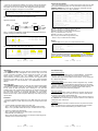
CTC Union Technologies Co.,Ltd.
Far Eastern Vienna Technology Center
(Neihu Technology Park)
8F, No. 60 Zhouzi St., Neihu, Taipei 114,
Taiwan
T +886-2-26591021
F +886-2-26590237
E [email protected]
[email protected]
[email protected]
H www.ctcu.com
2012 CTC Union Technologies Co., LTD.
All trademarks are the property of their respective owners.
Technical information in this document is subject to
change without notice.
User Guide
Gigabit Ethernet Fiber Switch
FRM220A-1002ES
Introduction
FRM220A-1002ES is an industrial temperature grade, dual copper to
dual fiber, Gigabit Ethernet managed switch designed to make conversion
between 10/100/1000Base-T and 100/1000Base-SX/LX with SFP
transceiver. Using SNMP and Web-based management in the FRM220 or
FRM220A chassis, the network administrator can monitor, configure and
control the activity of each chassis installed FRM220A-1002ES switch card.
The functions include Auto Laser Shutdown, Link Fault Forwarding,
bandwidth control, VLAN, Q-in-Q, duplex and speed configuration.
Features
Table of Contents
Introduction / Features
Specifications
Management Features
Panel / Installation
LED Indicators / Applications
Console Management
Port VLAN
802.1Q VLAN
Link Loss Forwarding
Upgrading
Troubleshooting
------- 1
------- 2
------- 2
------- 3
------- 4
------- 5-8
------- 8
------- 9-10
------- 11
------- 12
------- 13
-40 to +85°C “industrial” operating temperature range
10/100/1000Base-T to 100/1000Base-X (dual fiber rate)***
Network management via terminal, web or SNMP in FRM220 chassis
Stand-alone local console management via CH01M console port
Auto or Forced Ethernet mode; Auto MDI/MDIX
MTU 10.24K bytes (jumbo packets)
Supports 802.1Q tagging (16 groups) and 802.1ad Q-in-Q
VLAN port mapping feature
Supports Link Fault Pass Through (LFP) function
Supports Auto Laser Shutdown (ALS)
Digital Diagnostic Monitor of supported SFP modules
Provides 1Gb backplane Ethernet uplink in FRM220A
FRM220A-1002ES SFP sockets support a wide range of standard SFP
modules to address any network situation. Such as: Single-mode, Multimode, Multi-rate, Single fiber bi-directional, Coarse and Dense Wave
Division Multiplexing (CWDM and DWDM).
***Dual Rate Notice: When configuring for 100Base-FX, the SFP must
support Fast Ethernet data rate (e.g. 155Mbps). For Gigabit Ethernet, the
SFP must support 1.25Gbps data rate. A multi-rate SFP may also be used,
assuming it can cover both data rates.
WARNING: Fiber optic equipment may emit laser or infrared light that can
injure your eyes. Never look into an optical fiber or connector port. Always
assume that fiber optic cables are connected to an active laser light source.
Version 1.0 April 2012 Release
-1w w w . C T C U . c o m
w w w . C T C U . c o m
Panel
Figure 1. Front Panel of FRM220A-1002ES
Specifications
Optical Interface
Connector
2 x SFP cage (dual rate 100/1000)
Data rate
GbE (1.25Gbps optical rate), FE (125Mbps optical)
Duplex mode
Full duplex, Ethernet
Fiber Mode
Depends on SFP
Distance
Depends on SFP
Wavelength
Depends on SFP
Electrical Interface
Connector
2 x RJ-45, shielded
Data rate
10m/100m/1000mbps, Auto or Forced
Duplex mode
Auto, Forced Full or Half
Cable
Cat 5e or better
Distance
100meters maximum
Indications
LED (PWR, RPF,LFP, Link)
RJ45 indicators (Link, Full)
Power
(Card supports hot-swapping)
Input
Card : 12VDC, Standalone : AC, DC options
Consumption <8W
Dimensions
155 x 88 x 23mm (D x W x H)
Weight
120g
Temperature
-40 ~ 85°C (Operating), -40 ~ 85°C (Storage)
Humidity
0 ~ 95% non-condensing
Certification
CE, FCC, LVD, RoHS
MTBF
75000 hrs
Yellow:
1000M
2 x SFP ports, support
any 155M or 1.25G
transceiver
1002ES
Green:
100M
1
Off:
10M
2
LED Indicators
Power
3
Test
1, 2 Link
4
On: Link
Flash:
Activity
DEFAULT:
Use to recover lost password
or to return TCP/IP settings
to factory default values.
Off:
no link
Installation
Figure 2. Slide-in Card mounting of FRM220A-1002ES
Note: This converter card can be placed in CH01, CH01M 1-slot w/console, CH02M
2-slot w/console, CH02-NMC 2-slot with NMC or the full CH20 chassis.
Management Features
This model has no DIP Switch setting. When placed in FRM220-CH01M
with DB9 RS-232 console port, the card can be stand-alone configured
using an easy to use text menu system. When placed in a managed
chassis, the card is configured and monitored through the chassis NMC
(network management controller) via console, Telnet, Web HTTP or SNMP.
When placed in FRM220A 20 slot chassis with GSW/SNMP aggregate
card, this card supports gigabit Ethernet uplink.
CH20 Chassis
w/ NMC
CH02M Chassis
AC, DC, 2AC,
2DC, or AD
CH01 (CH01M)
AC, DC, 2AC,
2DC, or AD
CH02-NMC Chassis
AC, DC, 2AC, 2DC,
or AD
Follow all ESD precautions when handling the card and SFP modules.
-2-
-3-
w w w . C T C U . c o m
w w w . C T C U . c o m
LED Indicators
FX1
FX2
PWR
LINK
SPEED
FRM220A-1002ES converter works in point-to-point applications, either
as a stand-alone or when placed in FRM220-CH20 managed rack.
TEST
Linear Fiber Drops
RJ-45
Panel
1002ES
LED
PWR
Color
(Green)
FX1
(Green)
FX2
(Green)
TEST
(Red)
LINK
(RJ-45)
(Green)
SPEED
(RJ-45)
(Yellow)
(Green)
(Off)
State
On
Off
On
Off
On
Off
On
Flash
Off
On
Flash
Off
On
On
Off
Status
Power on
No Power or Card Disabled
Fiber Port 1 Link is OK
Fiber Port 1 Link is down
Fiber Port 2 Link is OK
Fiber Port 2 Link is down
Loop back test is active
During upgrade (rapid flashing)
Normal Operation
UTP link is OK
UTP link has active traffic
No UTP link
1000Base-T
100Base-TX
10Base-T
Applications
With its two optical and two electrical ports, FRM220A-1002ES works as
a copper to fiber or fiber to fiber converter, either as a stand-alone or when
placed in FRM220-CH20 managed rack.
Media Converter
1002ES
100M or 1G
Third party
Device
10/100/1000
Device
(electrical)
RJ45
SFP
SFP
1002ES
SFP
SFP
SFP
RJ45
RJ45
RJ45
10/100/1000
Device
10/100/1000
Device
10/100/1000
Device
Install OC3 or gigabit SFP modules appropriate for the fiber distance.
Console Management
When placed in the 1-slot CH01M or 2-slot CH02M chassis, this card can
be locally managed by connecting a simple serial terminal such as a
notebook computer that has an RS232 port or via a commonly available
USB to RS232 adapter. In Windows XP, HyperTerminal™ is an application
available for emulating a serial terminal. You can also search for TeraTerm
or PuTTY which are free alternatives, especially if your operating system
does not include HyperTerminal.
Settings
Baud Rate: 38,400 | Data bits: 8 | Parity bits: none | Stop bits: 1
Handshaking: none | Emulation: VT-100 | Default PASSWORD admin
Connect the serial cable to the CH01/2M's DB9. Run the terminal
emulation program. With power on, press [ESC], [space] or [Enter] to login
and display the "Main Menu" screen. The following is an example.
Optical
Install OC3 or gigabit SFP module appropriate for the fiber distance.
-4-
-5-
w w w . C T C U . c o m
w w w . C T C U . c o m
*****************************************
*** CTC UNION TECHNOLOGIES CO.,LTD
***
*** FRM220A-1002ES
Manager
***
*****************************************
Ver:[1.000-1.100-0.000-0.000]
[CH-01M
]
<1>
<2>
<3>
<4>
<5>
<6>
<7>
<8>
<P>
FX Port Explanation of Settings
<<
<1>
<2>
<3>
<4>
<5>
<6>
<7>
FX 1
Status and Configure
FX 2
Status and Configure
UTP 3
Status and Configure
UTP 4
Status and Configure
Device
Status and Configure
VLAN Tag
Status and Configure
Port VLAN
Status and Configure
Link Fault Pass-Through Status and Configure
Password change
FX status show “Link UP” with SFP that supports DOM
Example of Main Menu Console Screen, FRM220A-1002ES
Operation
Select any of the menu items by keying in the menu item number or letter.
Use the [ESC] to return to a previous menu. Any setting is immediately
applied to the transponder's circuitry but not saved in non-volatile ram. After
all of the parameter settings have been selected, go to the Device Status
sub-menu "5" from the main menu and press "5" to store the configuration
in non-volatile RAM (NVRAM).
Main Menu Navigation
<1>. Go to the sub menu for the Fiber port #1
<2>. Go to the sub menu for the Fiber port #2
<3>. Go to the sub menu for the UTP port #3
<4>. Go to the sub menu for the UTP port #4
<5>. Go to the Device setting menu
<6>. Go to the VLAN setting sub menu
<7>. Go to the port VLAN setting menu
<8>. Go to and configure the Link Fault Pass-thru settings
<P>. Modify the login password
<1>. Port Active: This allows disabling the fiber port, stopping all
transmissions through it.
<2>. Speed: This switch supports dual rate with selected optics for either
100Base-FX or 1000Base-X. This is a manual setting.
<3> Auto Laser Shutdown: ALS is a safety mechanism that will turn off
laser transmission in the event received optical signal is lost. ALS may be
enabled or disabled with this option.
<4> Loop Back Function: Loop back is a diagnostic utility to help isolate
link issues.
<5> Ingress Limit: Incoming packets can be limited with granularities of
64K, 1M and 10M.
<6> Egress Limit: Outgoing packets can be limited with granularities of
64K, 1M and 10M.
<7> SFP Digital Diagnostics: DOM or just DD are extra readable
parameters within the SFP module. Display those parameters here.
Example of reading Digital Diagnostics Information display.
<< Fiber D/D Function Status >>
Vendor Name
:[ FIBERXON INC.
Vendor Part Number :[ FTM-3125C-L40
Fiber Type
:[ Single ]
Wave Length
:[ 1310 nm ]
Link Length
:[ 0040 Km ]
Tx Power
:[ 01 dBm]
Rx Power
:[-12 dBm]
Rx Sensitivity
:[ 00 dBm]
Temperature
:[ 050 C ]
]
]
-6-
-7-
w w w . C T C U . c o m
w w w . C T C U . c o m
UTP Port Explanation of Settings
Example settings for Port VLAN, acting as two converters
<< UTP 3 Status and Configuration >>
<1> Port Active [ Enable ]
Link
[ Link Up
<2> Negotiation [ Auto ]
<3> Speed
[ 1000 ]
Status [ 1000 ]
Duplex
[ Full ]
Status [ Full ]
<5> Loop Back Function [ Disable ]
<6> Ingress Limit [ Unlimited ]
<7> Egress Limit [ Unlimited ]
<< Port VLAN Status and Configuration >>
]
<1>
<2>
<3>
<4>
UTP status show “Link UP” with 1000/Full connection
Port VLAN
FRM220A-1002ES supports a simple internal port mapping scheme.
Acts like 2
media
converters
RJ45
SFP
RJ45
SFP
1
2
3
4
A
[*]
[ ]
[*]
[ ]
B
[ ]
[*]
[ ]
[*]
802.1Q VLAN
<1>. Port Active: This allows disabling the UTP port, stopping all
transmissions through it.
<2>. Negotiation: This brings up the sub-menu to set auto or forced mode
for the UTP port.
<3>. Speed: This switch supports three rates. When Auto Negotiation is
enabled, speed is auto detected. If Forced mode is set, the speed can be
manually set here as 10M, 100M or 1000M.
<4>. Duplex: When set to Forced mode, the FX port can be configured to
either Full or Half Duplex. If speed is 1000, only Full Duplex is supported.
<5> Loop Back Function: Loop back is a diagnostic utility to help isolate
link issues.
<6> Ingress Limit: Incoming packets can be limited with granularities of
64K, 1M and 10M.
<7> Egress Limit: Outgoing packets can be limited with granularities of
64K, 1M and 10M.
1002ES
Group
:Fiber
:Fiber
:UTP
:UTP
<P> :Port VLAN
[Enable]
<ESC>:Go to Previous Menu.
<ESC> Go to previous menu.
LAN-B
[ Yes ]
<ESC> Go to previous menu.
<ESC> Logout
LAN-A
FX 1 Status and Configuration >>
FX Link
[ Up
]
SFP
[ Exist ]
D/D Function
Port Active [ Enable ]
Speed
[ 1000 ]
Auto Laser Shutdown [ Disable ]
Loop Back Function [ Disable ]
Ingress Limit [ Unlimited ]
Egress Limit [ Unlimited ]
SFP Digital Diagnostics
Optical
1002ES
SFP
RJ45
LAN-A
SFP
RJ45
LAN-B
<< 802.1Q VLAN status and Configuration >>
Port 1: <1> :VID [1]
<2>
Port 2: <3> :VID [1]
<4>
Port 3: <5> :VID [1]
<6>
Port 4: <7> :VID [1]
<8>
<V> VLAN Tag Function [ Disable ]
<T> Tag Type (Hex) [8100]
<Z> Go to VLAN Table Configuration Page.
:QinQ
:QinQ
:QinQ
:QinQ
Support
Support
Support
Support
[Disable]
[Disable]
[Disable]
[Disable]
The VID settings above for each port determine the tag that is added to all
incoming packets on that port. If the packets are already tagged, they may
be double tagged by enabling QinQ for that port. The actual VLAN function
will start when using the “V” menu item to “Enable” VLAN.
The tag type for normal c-tag (customer or inner tag) defaults to 0x8100.
802.1ad recommends 0x88a8 for s-tag (service provider or outer tag).
The “Z” item will open the static VLAN table that determines the action
taken on packets leaving ports.
Item | VLAN ID |
< 0 > |
1
|
< 1 > |
1
|
< 2 > |
1
|
< 3 > |
1
|
< 4 > |
1
|
< 5 > |
1
|
< 6 > |
1
|
< 7 > |
1
|
< 8 > |
1
|
< 9 > |
1
|
< a > |
1
|
Snip %<
<ESC>:Go to Port VID
Port 1
Unmodified
Unmodified
Unmodified
Unmodified
Unmodified
Unmodified
Unmodified
Unmodified
Unmodified
Unmodified
Unmodified
|
|
|
|
|
|
|
|
|
|
|
|
Port 2
Unmodified
Unmodified
Unmodified
Unmodified
Unmodified
Unmodified
Unmodified
Unmodified
Unmodified
Unmodified
Unmodified
|
|
|
|
|
|
|
|
|
|
|
|
Port 3
Unmodified
Unmodified
Unmodified
Unmodified
Unmodified
Unmodified
Unmodified
Unmodified
Unmodified
Unmodified
Unmodified
Configuration Page.
-8-
-9-
w w w . C T C U . c o m
w w w . C T C U . c o m
|
|
|
|
|
|
|
|
|
|
|
|
Port 4
Unmodified
Unmodified
Unmodified
Unmodified
Unmodified
Unmodified
Unmodified
Unmodified
Unmodified
Unmodified
Unmodified
Link Loss Forwarding
There are 16 VLAN groups available. For a group, enter the VID and then
select how the packet is sent out of that port (two fiber and two electrical).
The packet can be sent un-modified, sent untagged (meaning tag will be
removed), sent tagged or dropped as a non-member.
---------------------------------------------------------------------Egress mode Select :
<1>: Unmodified
<2>: Untagged
<3>: Tagged
<4>: Nonmember
<ESC> Go to previous menu. Please select an item.
If a packet is double tagged, the untag process will only remove the outer
tag. The packet will still egress with the original inner tag.
Application Example
Connection
carrying VID
100 & 200
Switch
LAN-A
VID=100
RJ45
LAN-B
VID=200
RJ45
SFP
1002ES
SFP
Optical
RJ45
LAN-A
RJ45
LAN-B
Step 1. Configure the FRM220A-1002ES Ethernet LAN ports to add tag for
packets coming from LAN A and LAN B.
<< 802.1Q VLAN status and Configuration >>
Port 1: <1> :VID [1]
<2>
Port 2: <3> :VID [1]
<4>
Port 3: <5> :VID [100]
<6>
Port 4: <7> :VID [200]
<8>
<V> VLAN Tag Function [ Enable ]
<T> Tag Type (Hex) [8100]
<Z> Go to VLAN Table Configuration Page.
:QinQ
:QinQ
:QinQ
:QinQ
Support
Support
Support
Support
[Disable]
[Disable]
[Disable]
[Disable]
Port 1
Tagged
Tagged
Unmodified
|
Port 2
|
Port 3
| Unmodified | Untagged
| Unmodified | Nonmember
| Unmodified | Unmodified
<<
Link Loss Forwarding Configuration >>
|
Condition
|
| Port 1 | Port 2 | Port 3 | Port 4 |
| Logical | Link Loss| Link Loss| Link Loss| Link Loss|
-----------------+----------+----------+----------+----------+----------|
Port 1 Power Off | <0>[AND] |
| <1>[ ] | <2>[ ] | <3>[ ] |
-----------------+----------+----------+----------+----------+----------|
Port 2 Power Off | <4>[AND] | <5>[ ] |
| <6>[ ] | <7>[ ] |
-----------------+----------+----------+----------+----------+----------|
Port 3 Power Off | <8>[AND] | <9>[ ] | <A>[ ] |
| <B>[ ] |
-----------------+----------+----------+----------+----------+----------|
Port 4 Power Off | <C>[AND] | <D>[ ] | <E>[ ] | <F>[ ] |
|
-----------------+----------+----------+----------+----------+----------+
<R> :Reset Settings.
<S> :Confirm and Save Settings.
<ESC>:Go to Previous Menu.
Example 1: FX port 1 Tx off if any port 2,3,4 Rx loss:
keyin 1,2,3 and keyin 0 to change 'and' to 'or'
Example 2: FX port 1 Tx off if all ports 2,3,4 Rx loss
keyin 1,2,3 and leave Port 1 as 'And'
Example 3: FX port 1 Tx off if port 3 Rx loss
keyin 2 (only one selected so logic doesn't care)
Press ‘s’ key to confirm and save settings.
Device
From the Main menu, press “5” to enter the Device menu
Step 2. Go to the static VLAN menu (menu item “Z”).
Item | VLAN ID |
< 0 > |
100
|
< 1 > |
200
|
< 2 > |
1
|
Snip %<
< e > |
1
|
< f > |
1
|
<ESC>:Go to Port VID
Link Loss Forwarding (LLF) is a method to report loss of Rx from any fiber
or UTP port and effectively stop Tx on any other fiber or UTP port. Since
FRM220A-1002ES has 4 ports, the LLF function is configured via a 4x4
matrix table and with 'and' or 'or' logic operations.
|
Port 4
| Nonmember
| Untagged
| Unmodified
Unmodified | Unmodified | Unmodified | Unmodified
Unmodified | Unmodified | Unmodified | Unmodified
Configuration Page.
<< Device Status and Configuration >>
<1> Device Active
[ Enable ]
<2> Flow Control
[ Enable ]
<3> Port Reset
<4> Factory Default
<5> Store Parameters
The entire device can be taken offline by disabling it. “Flow control”
(802.3X) is enabled by default, but may be disabled here. The “Port Reset”
function will warm start the switch. “Factory Default” will return all settings.
“Store parameters” is required so settings are remembered at next power
up.
- 10 -
- 11 -
w w w . C T C U . c o m
w w w . C T C U . c o m
Upgrading
Troubleshooting
The FRM220A-1002ES card may be firmware upgraded when it is placed
in the FRM220 with NMC management card. The user may use a local
console connection to the NMC, a remote Telnet (IP) connection, or a Web
based (HTTP) connection with any available browser. The NMC
communicates to all cards through a serial control bus. The upgrade code is
transferred to the NMC by way of TFTP server. All of these mentioned
upgrade methods are well documented in the FRM220-NMC Operation
Manual.
About SFP Units
The FRM220A-1002ES accepts any SFP unit that complies with the MSA
standard and is rated for a data rate of 1.25Gbps for GbE or 125/155Mbps
for FE. Follow all ESD precautions when handling the card and SFP
modules. Fiber optic components and cables are very sensitive to dirt, dust
and mishandling, especially in high-speed networks. Dirty or mistreated
fiber may cause errors and an unwanted degradation of signal quality.
Remove the dust caps on SFP and patch cables only when ready to plug in
optical cables.
Installation
CTC Union supplied SFP modules are of the Bale Clasp type. The bale
clasp SFP module has a bale clasp that secures the module into the SFP
cage.
• Inserting a Bale Clasp SFP Module into a SFP cage
Step 1 Close the bale clasp upward before inserting the SFP module.
Step 2 Line up the SFP module with the port, and slide it into the cage.
UTP Port link problems
The TP port of the 1002ES supports 10/100/1000Base-T. Avoid Duplex
Mismatch conditions by connecting auto to auto or forced to forced.
The UTP port supports auto-polarity and auto MDI-X, so any straight Cat
5e or better cable will work.
FX Port link problems
The FX port supports FE or GbE by manual configuration only. The SFP
used must support FE or gigabit Ethernet speed depending on the setting.
There is no recognized standard for automatically determining FE or GbE
speed from the transceiver. For link problems please double check the
speed is set according to the SFP being deployed.
Other link problems
Check if LFP is enabled. If LFP is enabled, the converter requires good
link on both FX and TP ports. If either has no link, then the other will also
not link. So, if link testing, please disable LFP.
FX link can be check by using an LC simplex cable to loop the SFP Tx to
Rx. CAUTION: Do not do this when the TP port is linked to a live network or
a broadcast storm could result.
Conclusion
Once configuration has been confirmed and FX / TP ports check for link
state, most problems end up being cables. Swap different UTP and fiber
cables, and SFP modules before blaming the media converter.
• Removing a Bale Clasp SFP Module
Step 1 Open the bale clasp on the SFP module. Press the clasp
downward with your index finger.
Step 2 Grasp the SFP module between your thumb and index finger and
carefully remove it from the SFP cage.
- 12 -
- 13 -
w w w . C T C U . c o m
w w w . C T C U . c o m