1
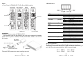
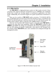
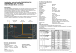
CTC Union Technologies Co.,Ltd.
Far Eastern Vienna Technology Center
(Neihu Technology Park)
8F, No. 60 Zhouzi St., Neihu, Taipei 114,
Taiwan
T +886-2-26591021
F +886-2-26590237
E [email protected]
[email protected]
[email protected]
H www.ctcu.com
2009-2011 CTC Union Technologies Co., LTD.
All trademarks are the property of their respective owners.
Technical information in this document is subject to
change without notice.
User Guide
G.703E1 and T1(DS1) over Fiber
FRM220-E1/T1
(Fiber Optical Modem)
Introduction
The FRM220-E1/T1 family are stand-alone fiber media converters available
in a number of different models that also act as cards for placement in the
FRM220 Platform media converter chassis. The FRM220-E1/T1R is a fiber
media transport for both G.703 E1 120 ohm and T1 100 ohm transmission
with RJ45 connector. The FRM220-E1B model provides unbalanced E1 75
ohm coaxial connections. All media converters are available with either
multi-model 2km or single-mode 15/30/50/80/120km optical transceivers
and with connectors for SC, ST, FC. In single fiber WDM mode, the SC
connector is also available in 20, 40, 60 and 80km. When the FRM220E1/T1 card is placed in the FRM220 rack with SNMP management, the card
status, type, version, fiber link status, E1 or T1 link status and alarms can all
be displayed. Configuration in also available to enable or disable the port,
reset the port, do far end fault setting and initiate local or far end loopback
tests.
Features
Table of Contents
Introduction & Features
Specifications
Panel & Installation
LED Indicators & E1 Pinout
DIP Location, DIP 1 Setting
DIP 2 Setting
DIP 3 Setting
Loop Back Tests
Console Operation
SFP Modules
------- 1
------- 2-3
------- 4
------- 5
------- 6
------- 7
------- 8
------- 9
------- 10-11
------- 12-13
Interface connectors: RJ-48C for E1T1R, BNC x 2 for E1B
Supports fiber connection to FRM220-DATA and FRM220-ET100 (E1
only)
E1/T1, Line Code, Full or Fractional setting
Frame setting, E1(CCS/CAS), T1(D4/ESF)
CRC enable disable setting
Idle code setting (0x7E or 0xFF)
Auto laser shutdown setting
Auto generation of blue (AIS) alarm enable disable setting
AIS always generated in the event of fiber receive loss of signal
Active timeslot number setting (E1 CCS 1-31, E1 CAS 1-30, T1 1-24
Base timeslot setting (E1 CCS 1-31, E1 CAS 1-15 and 17-31, T1 1-24)
Loop Back (LLB,RLB,RRLB) set by DIPSW on front panel (when
standalone)
Timing source setting (Remote recovery, Internal oscillator, Local
recovery E1/T1)
Read DDOM of SFP (SFP model only)
Version 1.1 November 2011 (update)
-1w w w . C T C U . c o m
w w w . C T C U . c o m
Technical Specifications
Optical Specifications
Connector Type 1x9 Transceiver: ST,SC,FC or WDM (single fiber)
SFP Transceiver: SFP or SFP WDM (single fiber)
Optical mode
Multi-mode or Single-mode
Wave length
1310nm,1550nm,WDM
Power Margin
11dB(2Km,M/M) ,12dB~ 35 dB(15 ~ 120Km,S/M)
Data rate
36.864Mbps
Line coding
Scrambled NRZ
Bit Error Rate
Less than 10e-10
Test Loops
-LLB (Local Loop Back)
-RLB (Remote Loop Back)
-RRLB (Far end remote loop back)
E1 Specifications
Ports
Standards
Framing
Line Code
Data Rate
Min. Rx Level
Line impedance
1 port
ITU-T G.703,G.704,G.823
Unframed, PCM30(CAS) or PCM31(CCS)
HDB3/AMI
2.048 Mbps
-43dB
75 ohm for BNC type
120 ohm for RJ-48C type
Pulse amplitude Nominal 2.37+/-10% for 75 ohms
Nominal 3.0+/-10% for 120 ohms
Zero amplitude +/-0.1V
Connector
E1/T1: RJ-45 E1: BNC x 2
Test Loops
-LLB (Local Loop Back)
-RLB (Remote Loop Back)
-RRLB (Far end remote loop back)
Bit Error Rate
Less than 10e-10
T1 Specifications
Ports
Standards
Framing
Line Code
Data Rate
Min. Rx Level
Line impedance
Pulse amplitude
Zero amplitude
Connector
Test Loops
Bit Error Rate
1 port
ITU-T G.703,G.704,G.824
Unframed, D4(SF) or ESF
B8ZS/AMI
1.544 Mbps
-36dB
100 ohm
Nominal 3.0+/-20%
+/-0.15V
RJ-45
-LLB (Local Loop Back)
-RLB (Remote Loop Back)
-RRLB (Far end remote loop back)
Less than 10e-10
Environment
Operating
Storage
Humidity
0°C – 50°C
0°C – 70°C,
10 – 90%, (non-condensing)
Power
Adapter:
Built-in AC
Built-in DC
Consumption
12V DC 1A
100~240 VAC
18~72VDC
<4 watts
Dimensions: (W x D x H) mm
E1/T1-DC12
88 × 160 × 24
E1/T1-AC
135 × 201 × 35
E1/T1-DC48
135 × 201 × 35
E1/T1-AD
135 × 201 × 35
Weight
FRM220-E1/T1 (card): 140g
FRM220-E1/T1-DC12: 400g
FRM220-E1/T1-DC48: 750g
FRM220-E1/T1-AC: 750g
FRM220-E1/T1-AD: 800g
-2-
-3-
w w w . C T C U . c o m
w w w . C T C U . c o m
LED Indicators
Panel
Front Panel of FRM220-E1/T1 (RJ-45 and BNC models)
TDM on Fiber
LED
PWR
(Green)
FX LINK
(Green)
E1T1
SIG
TEST
(Green)
(Red)
RD
(Green)
TD
(Green)
SYN
(Green)
AIS
(Green)
LED indicators
E1/T1 on RJ45
FRM220-E1/T1
Loop back (manual)
Installation
Slide-in Card mounting of FRM220-E1/T1
This converter card can be placed in the CH01 with external AC adapter,
CH01 w/built-in power, CH01M, CH-02M, CH02-NMC, CH08 or the full CH20 chassis.
CH01 Chassis
CH01M Chassis
CH02M Chassis
AC, DC, 2AC, 2DC, or AD
State
On
Flash
Off
On
Flash
Off
On
Off
On
Off
On
Off
Flash
On
Off
Flash
On
Off
On
Off
Status
Power on
During upgrade
Power off or port disabled
Fiber link
Remote side sync loss
Fiber no link
E1/T1 Signal present
Loss of Signal
Loop Back Test active
Normal operation
Receive zero data
Receive one data
Data flow
Transmit zero data
Transmit one data
Data flow
E1/T1 Sync OK
LOS or LOF
Unit is transmitting AIS
No local AIS alarm
E1 Pin Assignment
The RJ-45 connector follows USOC RJ48C wiring standard for a
terminating unit. RJ48C utilizes pairs 1&2 and 4&5. In a terminating unit,
pair 1&2 is receive signal while pair 4&5 is transmit signal.
CH02-NMC Chassis
AC, DC, 2AC, 2DC, or AD
FRM220-CH20
Follow all ESD precautions when handling the card.
Pin 1 – RxRing
Pin 4 – TxRing
Pin 2 - RxTip
Pin 5 - TxTip
-4-
-5-
w w w . C T C U . c o m
w w w . C T C U . c o m
DIP Switches On PCB
DIP SW2
Rx
Tx
SW1
Tx
Rx
SW2
DIP SW1
1
SW3
SW STATE
1
OFF
ON
Function
E1/T1 Setting
E1
T1
2
OFF
ON
Line Code Setting
HDB3(E1)/B8ZS(T1)
AMI
3
OFF
ON
Full or Fraction Setting
Full E1/T1
Fractional E1/T1
4
OFF
ON
Frame setting
CCS(E1), D4(SF)(T1)
CAS(E1), ESF(T1)
5
5
OFF
ON
CRC setting
Disable
Enable
6
6
OFF
ON
Auto transmitted AIS when received signal loss
Disable
Enable
2
3
4
7,8
7
OFF
ON
OFF
ON
8
OFF
OFF
ON
ON
E1/T1 transmitted timing setting
Recovery from remote side E1/T1 or DATA.
Internal oscillator.
Recovery from local E1/T1 receive.
Reserved
1,2,3,4,5
SW STATE
Function
1
OFF
2
OFF
3
OFF
4
OFF
5
OFF
Fraction timeslot number
Full E1/T1
1 timeslot
ON
OFF
OFF
OFF
OFF
OFF
ON
OFF
OFF
OFF
2 timeslot
ON
ON
OFF
OFF
OFF
3 timeslot
OFF
OFF
ON
OFF
OFF
4 timeslot
ON
OFF
ON
OFF
OFF
5 timeslot
OFF
ON
ON
OFF
OFF
6 timeslot
ON
ON
ON
OFF
OFF
7 timeslot
OFF
OFF
OFF
ON
OFF
8 timeslot
ON
OFF
OFF
ON
OFF
9 timeslot
OFF
ON
OFF
ON
OFF
10 timeslot
ON
ON
OFF
ON
OFF
11 timeslot
OFF
OFF
ON
ON
OFF
12 timeslot
ON
OFF
ON
ON
OFF
13 timeslot
OFF
ON
ON
ON
OFF
14 timeslot
ON
ON
ON
ON
OFF
15 timeslot
OFF
OFF
OFF
OFF
ON
16 timeslot
17 timeslot
ON
OFF
OFF
OFF
ON
OFF
ON
OFF
OFF
ON
18 timeslot
ON
ON
OFF
OFF
ON
19 timeslot
OFF
OFF
ON
OFF
ON
20 timeslot
ON
OFF
ON
OFF
ON
21 timeslot
OFF
ON
ON
OFF
ON
22 timeslot
ON
ON
ON
OFF
ON
23 timeslot
OFF
OFF
OFF
ON
ON
24 timeslot
25 timeslot (T1 does not use TS25~31)
ON
OFF
OFF
ON
ON
OFF
ON
OFF
ON
ON
26 timeslot
ON
ON
OFF
ON
ON
27 timeslot
OFF
OFF
ON
ON
ON
28 timeslot
ON
OFF
ON
ON
ON
29 timeslot
OFF
ON
ON
ON
ON
30 timeslot
ON
ON
ON
ON
ON
31 timeslot
6
6
7
8
Auto laser shutdown setting
OFF
Disable
ON
Enable
7
OFF
Unused timeslot idle code
0x7E
ON
0xFF
8
Reserved
-6-
-7-
w w w . C T C U . c o m
w w w . C T C U . c o m
DIP SW3
1,2,3,4,5
SW STATE
Function
1
OFF
2
OFF
3
OFF
4
OFF
5
OFF
First timeslot of contiguous TS setting
Full E1/T1
Timeslot 1
ON
OFF
OFF
OFF
OFF
OFF
ON
OFF
OFF
OFF
Timeslot 2
ON
ON
OFF
OFF
OFF
Timeslot 3
OFF
OFF
ON
OFF
OFF
Timeslot 4
ON
OFF
ON
OFF
OFF
Timeslot 5
OFF
ON
ON
OFF
OFF
Timeslot 6
ON
ON
ON
OFF
OFF
Timeslot 7
OFF
OFF
OFF
ON
OFF
Timeslot 8
Timeslot 9
ON
OFF
OFF
ON
OFF
OFF
ON
OFF
ON
OFF
Timeslot 10
ON
ON
OFF
ON
OFF
Timeslot 11
OFF
OFF
ON
ON
OFF
Timeslot 12
ON
OFF
ON
ON
OFF
Timeslot 13
OFF
ON
ON
ON
OFF
Timeslot 14
ON
ON
ON
ON
OFF
Timeslot 15
OFF
OFF
OFF
OFF
ON
Timeslot 16 (except if E1 is CAS)
ON
OFF
OFF
OFF
ON
Timeslot 17
OFF
ON
OFF
OFF
ON
Timeslot 18
ON
ON
OFF
OFF
ON
Timeslot 19
OFF
OFF
ON
OFF
ON
Timeslot 20
ON
OFF
ON
OFF
ON
Timeslot 21
OFF
ON
ON
OFF
ON
Timeslot 22
ON
ON
ON
OFF
ON
Timeslot 23
OFF
OFF
OFF
ON
ON
Timeslot 24
ON
OFF
OFF
ON
ON
Timeslot 25 (T1 does not use TS25~31)
OFF
ON
OFF
ON
ON
Timeslot 26
ON
ON
OFF
ON
ON
Timeslot 27
OFF
OFF
ON
ON
ON
Timeslot 28
ON
OFF
ON
ON
ON
Timeslot 29
OFF
ON
ON
ON
ON
Timeslot 30
ON
ON
ON
ON
ON
Timeslot 31
6, 7
6, 7
Reserved
8
8
OFF
Loopback Group
Fiber
ON
E1/T1
Panel
Switch
LB1
OFF
LB2
OFF
Loopback Group
Loop Back DIsabled
ON
OFF
Local Loop Back (LLB)
OFF
ON
Remote Loop Back (RLB)
ON
ON
Request Remote Loop Back (RRLB)
Loop back Testing (LBT):
This fiber modem incorporates loop back features which allow loop back
testing to confirm that the fiber loop and interface transceivers are operating
normally or not. Loop back is enabled by DIP switch or via NMC manager in
FRM220 chassis
E1/T1 Port Loop Back
LLB
Local
Loop Back
Local Side
Remote Side
Local Side
Remote Side
Local Side
Remote Side
Local Side
Remote Side
RLB
Remote
Loop Back
RRLB
Request
Remote
Loop Back
Fiber Loop Back
LLB
Local
Loop Back
RLB
Remote
Loop Back
RRLB
Request
Remote
Loop Back
-8-
-9-
w w w . C T C U . c o m
w w w . C T C U . c o m
Console Operation
E1 Parameter settings
FRM220-E1/T1 may be configured with a local serial console when the card is placed
in either a CH01M or a CH02M chassis with serial console port connection. When
console port is chosen for configuration, the DIP switch settings have no effect.
Connect serial console using terminal emulation with settings:
38400, 8 bits, no parity, 1 stop, no low control (Press Enter key first to display menu)
***************************************************
***
CTC UNION TECHNOLOGIES CO., LTD.
***
*** FRM220 E1/T1
Ver:1.000-1.130-1.020 ***
[Local] ***************************************************
<1> :Port Active :[Enable]
CH-01M
FX Link
:[Up]
FX Signal :[Yes]
FX FEF
:[Off]
RD State
:[Flash]
TD State :[Flash]
Test State :[Normal]
E1/T1 Signal:[Normal] Frame Sync:[Loss]
Receive AIS:[No]
Connector
:[BNC]
<2> :E1/T1 Parameter setting.
<3> :Timing Source
:[Recovery from remote side]
<4> :Auto Laser Shutdown(ALS) :[Disable]
<5> :Active Rate
:[Full E1]
<6> :Start Timeslot
:[Full E1]
<7> :Loop Back Setting
:[Off]
<8> :Port Reset.
<9> :Set to Default.
Small Form Pluggable(SFP):[Off] Digital Diagnostic(D/D):[Off]
<N>
<P>
<Q>
<S>
E1/T1 Parameter Set Menu.
<1> :E1/T1 Select
:[E1]
<2> :Line Code Setting
:[HDB3(E1)/B8ZS(T1)]
<3> :Full/Fractional
:[Fractional]
<4> :Framer Setting
:[CCS(E1)/D4(T1)]
<5> :CRC Setting
:[Enable]
<6> :Rx Loss Tx AIS
:[Disable]
<7> :Unused Timeslot Code :[0x7E]
<ESC>: Go to previous menu. Please select an item.
1. E1/T1 Select: For converter with RJ-45, selects between E1 and T1 operation mode
2. Line code setting: For E1, selects between HDB3 and AMI; for T1, selects between
B8ZS and AMI
3. Full/Fractional: Selects between unframed (2048K) or fractional (nx64) frame mode
4. Framer setting: When set for fractional operation, this selects the framer setting
5. CRC Setting: This enables or disables CRC4 for E1 or CRC6 for T1
6. RX Loss Tx AIS: Normal protocol requires AIS be transmitted in the event of receive
signal loss. Enabling this provides this function.
7. Unused Timeslot code: The unused timeslots in fractional mode may stuff either 7E
or FF value
Active Rate
:Go to the Remote Menu.
:Password Setup.
:Quit Terminal.
:Save Setting Value.
Description of Functions
1. Port Active: Use this to enable or disable this device
2. E1/T1 Parameter setting: Opens a sub-menu, explained on next page
3. Timing source: Selects between Internal oscillator, recover from E1/T1 or
recover from remote (fiber)
4. Auto Laser Shutdown: Enable or disable the ALS safety function
5. Active Rate: sets the nx64 rate, shown on next page
6. Start timeslot: Sets the first timeslot of a contiguous group of nx64 timeslots
7. Loop Back Setting: Sets the fiber and E1/T1 loop back, shown on next page
8. Port Reset: Resets the CPLD chip and initializes the CPU
9. Set to default: Returns all settings to factory default
D. Display SFP Information: Applicable only if converter has SFP module
N. Go to remote card menu: Using EOC, enter the configuration screen for the remote
card
P. Password Setup: To protect against unauthorized access, a console password can
be setup.
Q. Quit Terminal: leaves the terminal menu
S. Save Setting Value: Stores the parameter settings to the card
IMPORTANT: Settings must be saved or they revert at next power on.
Active Rates :
<1>:64K
<2>:128K <3>:192K <4>:256K <5>:320K <6>:384K
<8>:512K
<9>:576K <A>:640K <B>:704K <C>:768K <D>:832K <E>:896K
<G>:1024K
<H>:1088K <I>:1152K <J>:1216K <K>:1280K <L>:1344K <M>:1408K
<O>:1536K
<P>:1600K <Q>:1664K <R>:1728K <S>:1792K <T>:1856K <U>:1920K
<W>:Full
<ESC>: Go to previous menu. Please select an item.
<7>:448K
<F>:960K
<N>:1472K
<V>:1984K
First Timeslot
Start timeslot :
<1>:TS1 <2>:TS2 <3>:TS3 <4>:TS4 <5>:TS5
<9>:TS9 <A>:TS10 <B>:TS11 <C>:TS12 <D>:TS13
<H>:TS17 <I>:TS18 <J>:TS19 <K>:TS20 <L>:TS21
<P>:TS25 <Q>:TS26 <R>:TS27 <S>:TS28 <T>:TS29
<ESC>: Go to previous menu. Please select an
<6>:TS6
<E>:TS14
<M>:TS22
<U>:TS30
item.
<7>:TS7
<F>:TS15
<N>:TS23
<V>:TS31
<8>:TS8
<G>:TS16
<O>:TS24
<W>:Full
The active rate and first timeslot are used to select the contiguous range of
timeslots to carry data/voice within the framed E1 or T1 transmission.
- 10 -
- 11 -
w w w . C T C U . c o m
w w w . C T C U . c o m
Monitoring SFP models and SFP with DDOM
***************************************************
***
CTC UNION TECHNOLOGIES CO., LTD.
***
*** FRM220 CH01M E1/T1 Ver:1.000-1.130-1.020 ***
[Local] ***************************************************
Display SFP information.
Vendor Name
:[ FIBERXON INC.
]
Vendor Part Number :[ FTM-3125C-L40
]
Fiber Type
:[ Single ]
Tx Wave Length
:[ 1310nm ]
Rx Wave Length
:[ 1310nm ]
Link Length
:[
40km ]
Tx Power
:[ +01dBm ]
Rx Power
:[ +02dBm ]
Rx Sensitivity
:[ +00dBm ]
Temperature
:[ +39C
]
Installation of SFP Modules
CTC Union supplied SFP modules are of the Bale Clasp type. The bale
clasp SFP module has a bale clasp that secures the module into the SFP
cage.
Inserting a Bale Clasp SFP Module into a SFP cage
Step 1 Close the bale clasp upward before inserting the SFP module.
Step 2 Line up the SFP module with the port, and slide it into the cage.
Removing a Bale Clasp SFP Module
Step 1 Open the bale clasp on the SFP module. Press the clasp
downward with your index finger.
Step 2 Grasp the SFP module between your thumb and index finger and
carefully remove it from the SFP cage.
Identifying E1/T1 Card Version
Upgrading
FRM220-E1/T1 card may be firmware upgraded when it is placed in the
FRM220 with NMC management card. The user may use a local console
connection to the NMC, a remote Telnet (IP) connection, or a Web based
(HTTP) connection with any available browser. The NMC communicates to
all cards through a serial RS485 control bus. The upgrade code is
transferred to the NMC by way of TFTP server. All of these mentioned
upgrade methods are well documented in the FRM220-NMC Software
Operation Manual.
[Local]
***************************************************
***
CTC UNION TECHNOLOGIES CO., LTD.
***
*** FRM220 CH01M E1/T1 Ver:1.000-1.130-1.020 ***
***************************************************
Each page viewed from the console menu has a ‘header’ that can identify
the version of the E1/T1 card. There are three (3) fields shown. From left to
right, these fields represent hardware, firmware and CPLD versions.
In the above example, the card is
About SFP Units
The FRM220-E1/T1(S) accepts any SFP unit that complies with the MSA
standard. Follow all ESD precautions when handling the card and SFP
modules. Fiber optic components and cables are very sensitive to dirt, dust
and mishandling, especially in high-speed networks. Dirty or mistreated
fiber may cause errors and an unwanted degradation of signal quality.
Remove the dust caps on SFP only when ready to plug in optical cables.
Hardware Version: 1.000
Firmware Version: 1.130
CPLD Version: 1.020
When choosing SFP optical modules, the SFP must be able to support
the required data rate. The optical data rate of this device is 36.864Mbps.
Make sure the SFP modules chosen are suitable for the required data rate.
- 12 -
- 13 -
w w w . C T C U . c o m
w w w . C T C U . c o m