1
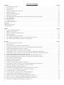
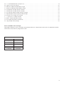
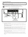
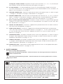
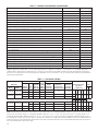
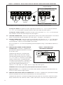
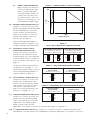
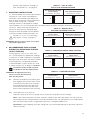
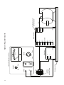
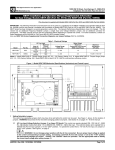
Series 5 Inverter
NEMA 4X, IP-65
Installation and Operating Manual
4/06
MN781BW
TABLE OF CONTENTS
Page
Section
1 Quick-Start Instructions . . . . . . . . . . . . . . . . . . . . . . . . . . . . . . . . . . . . . . . . . . . . . . . . . . . . . . . . . . . . . . . . 4
2 Safety Warning . . . . . . . . . . . . . . . . . . . . . . . . . . . . . . . . . . . . . . . . . . . . . . . . . . . . . . . . . . . . . . . . . . . . . . 5
3 Introduction . . . . . . . . . . . . . . . . . . . . . . . . . . . . . . . . . . . . . . . . . . . . . . . . . . . . . . . . . . . . . . . . . . . . . . . . . 6
4 Important Application Information . . . . . . . . . . . . . . . . . . . . . . . . . . . . . . . . . . . . . . . . . . . . . . . . . . . . . . . 12
5 Wiring Instructions . . . . . . . . . . . . . . . . . . . . . . . . . . . . . . . . . . . . . . . . . . . . . . . . . . . . . . . . . . . . . . . . . . . 13
6 Setting Selectable Jumpers . . . . . . . . . . . . . . . . . . . . . . . . . . . . . . . . . . . . . . . . . . . . . . . . . . . . . . . . . . . . 16
7 Mounting Instructions . . . . . . . . . . . . . . . . . . . . . . . . . . . . . . . . . . . . . . . . . . . . . . . . . . . . . . . . . . . . . . . . 19
8 Recommended High Voltage Dielectric Withstand Testing (Hi-Pot Testing) . . . . . . . . . . . . . . . . . . . . . . . . . 19
9 Drive Operation . . . . . . . . . . . . . . . . . . . . . . . . . . . . . . . . . . . . . . . . . . . . . . . . . . . . . . . . . . . . . . . . . . . . . 21
10 AC Line Fusing . . . . . . . . . . . . . . . . . . . . . . . . . . . . . . . . . . . . . . . . . . . . . . . . . . . . . . . . . . . . . . . . . . . . . 21
11 Diagnostic LEDs . . . . . . . . . . . . . . . . . . . . . . . . . . . . . . . . . . . . . . . . . . . . . . . . . . . . . . . . . . . . . . . . . . . . 21
12 Trimpot Adjustments . . . . . . . . . . . . . . . . . . . . . . . . . . . . . . . . . . . . . . . . . . . . . . . . . . . . . . . . . . . . . . . . . 22
Appendix . . . . . . . . . . . . . . . . . . . . . . . . . . . . . . . . . . . . . . . . . . . . . . . . . . . . . . . . . . . . . . . . . . . . . . . . . . . . . 26
Baldor District Offices . . . . . . . . . . . . . . . . . . . . . . . . . . . . . . . . . . . . . . . . . . . . . . . . . . . . . . . . . . . . . . . . . . . . 27
Limited Warranty . . . . . . . . . . . . . . . . . . . . . . . . . . . . . . . . . . . . . . . . . . . . . . . . . . . . . . . . . . . . . . . . . . . . . . . 28
Tables
Page
1 Jumper Selectable Features . . . . . . . . . . . . . . . . . . . . . . . . . . . . . . . . . . . . . . . . . . . . . . . . . . . . . . . . . . . . 8
2 Optional Accessories . . . . . . . . . . . . . . . . . . . . . . . . . . . . . . . . . . . . . . . . . . . . . . . . . . . . . . . . . . . . . . . . . . 8
3 General Performance Specifications . . . . . . . . . . . . . . . . . . . . . . . . . . . . . . . . . . . . . . . . . . . . . . . . . . . . . 10
4 Electrical Ratings . . . . . . . . . . . . . . . . . . . . . . . . . . . . . . . . . . . . . . . . . . . . . . . . . . . . . . . . . . . . . . . . . . . . 10
5 Terminal Block Wiring Information . . . . . . . . . . . . . . . . . . . . . . . . . . . . . . . . . . . . . . . . . . . . . . . . . . . . . . . 13
6 Drive Operating Condition and Run/Fault Relay Contact Status . . . . . . . . . . . . . . . . . . . . . . . . . . . . . . . . . 16
7 Drive Operating Condition and Status LED Indicator . . . . . . . . . . . . . . . . . . . . . . . . . . . . . . . . . . . . . . . . . 22
Figures
Page
1 Quick-Start Connection Diagram . . . . . . . . . . . . . . . . . . . . . . . . . . . . . . . . . . . . . . . . . . . . . . . . . . . . . . . . . 4
2 Control Layout . . . . . . . . . . . . . . . . . . . . . . . . . . . . . . . . . . . . . . . . . . . . . . . . . . . . . . . . . . . . . . . . . . . . . . . 9
3 Catalog No. ID5601 Mechanical Specifications . . . . . . . . . . . . . . . . . . . . . . . . . . . . . . . . . . . . . . . . . . . . . 11
4 Catalog Nos. ID5602, ID5203, ID5403, ID5405 Mechanical Specifications . . . . . . . . . . . . . . . . . . . . . . . . 11
5 Maximum Allowed Motor Torque vs. Speed . . . . . . . . . . . . . . . . . . . . . . . . . . . . . . . . . . . . . . . . . . . . . . . . 12
6 Open Ventilated Motor with External Fan Cooling . . . . . . . . . . . . . . . . . . . . . . . . . . . . . . . . . . . . . . . . . . . 12
7 Catalog Nos. ID5601, ID5602 AC Line Input, Motor, and Ground Connections . . . . . . . . . . . . . . . . . . . . . 13
8 Catalog Nos. ID5203, ID5403, ID5405 AC Line Input, Motor, and Ground Connections . . . . . . . . . . . . . . 14
9 Remote Main Speed Potentiometer Connection . . . . . . . . . . . . . . . . . . . . . . . . . . . . . . . . . . . . . . . . . . . . 14
10 Remote Start/Stop Switch Connection with Normally Open Stop Contact . . . . . . . . . . . . . . . . . . . . . . . . 15
11 Remote Start/Stop Switch Connection with Normally Closed Stop Contact . . . . . . . . . . . . . . . . . . . . . . . 15
12 Start/Stop Function Eliminated . . . . . . . . . . . . . . . . . . . . . . . . . . . . . . . . . . . . . . . . . . . . . . . . . . . . . . . . . 15
13 Voltage Following Connections . . . . . . . . . . . . . . . . . . . . . . . . . . . . . . . . . . . . . . . . . . . . . . . . . . . . . . . . . 15
14 Enable Circuit Connection . . . . . . . . . . . . . . . . . . . . . . . . . . . . . . . . . . . . . . . . . . . . . . . . . . . . . . . . . . . . . 16
15 Run/Fault Relay Output Contacts Connection . . . . . . . . . . . . . . . . . . . . . . . . . . . . . . . . . . . . . . . . . . . . . . 16
16 Catalog Nos. ID5601, ID5602 AC Line Input Voltage Selection (Jumper J1) . . . . . . . . . . . . . . . . . . . . . . . 16
17 Removing Jumper J1 on Catalog Nos. ID5601, ID5602 . . . . . . . . . . . . . . . . . . . . . . . . . . . . . . . . . . . . . . 17
18 Motor Horsepower Selection (Jumper J2) . . . . . . . . . . . . . . . . . . . . . . . . . . . . . . . . . . . . . . . . . . . . . . . . . 17
19 Automatic Ride-Through or Manual Restart Selection (Jumper J3) . . . . . . . . . . . . . . . . . . . . . . . . . . . . . . 17
20 60 Hz and 50 Hz Motor Selection (Jumpers J4 and J5) . . . . . . . . . . . . . . . . . . . . . . . . . . . . . . . . . . . . . . 17
21 Available Torque vs. Output Frequency . . . . . . . . . . . . . . . . . . . . . . . . . . . . . . . . . . . . . . . . . . . . . . . . . . . 18
22 120 Hz and 100 Hz Drive Output Frequency Selection . . . . . . . . . . . . . . . . . . . . . . . . . . . . . . . . . . . . . . . 18
23 Fixed or Adjustable Boost Selection (Jumper J6) . . . . . . . . . . . . . . . . . . . . . . . . . . . . . . . . . . . . . . . . . . . . 18
24 Regenerative or DC Injection Braking Selection (Jumper J7) . . . . . . . . . . . . . . . . . . . . . . . . . . . . . . . . . . . 18
25 “Run” or “Fault” Output Relay Operation Selection (Jumper J8) . . . . . . . . . . . . . . . . . . . . . . . . . . . . . . . . . 19
26 Normally Open or Closed Stop Contact Selection (Jumper J9) . . . . . . . . . . . . . . . . . . . . . . . . . . . . . . . . . 19
27 Constant or Variable Torque Selection (Jumper J10) . . . . . . . . . . . . . . . . . . . . . . . . . . . . . . . . . . . . . . . . . 19
ii
28
29
30
31
32
33
34
35
36
37
38
39
40
I 2 t Overload Selection (Jumper J11) . . . . . . . . . . . . . . . . . . . . . . . . . . . . . . . . . . . . . . . . . . . . . . . . . . . . .
Typical Hi-Pot Test Setup . . . . . . . . . . . . . . . . . . . . . . . . . . . . . . . . . . . . . . . . . . . . . . . . . . . . . . . . . . . . . .
Minimum Speed Trimpot (MIN) Range . . . . . . . . . . . . . . . . . . . . . . . . . . . . . . . . . . . . . . . . . . . . . . . . . . . .
Maximum Speed Trimpot (MAX) Range . . . . . . . . . . . . . . . . . . . . . . . . . . . . . . . . . . . . . . . . . . . . . . . . . . .
Acceleration Trimpot (ACCEL) Range . . . . . . . . . . . . . . . . . . . . . . . . . . . . . . . . . . . . . . . . . . . . . . . . . . . . .
Deceleration Trimpot (DECEL) Range . . . . . . . . . . . . . . . . . . . . . . . . . . . . . . . . . . . . . . . . . . . . . . . . . . . . .
DC Injection Brake Trimpot (DECEL) Range . . . . . . . . . . . . . . . . . . . . . . . . . . . . . . . . . . . . . . . . . . . . . . . .
Slip Compensation Trimpot (COMP) Range . . . . . . . . . . . . . . . . . . . . . . . . . . . . . . . . . . . . . . . . . . . . . . . .
Current Limit Trimpot (CL) Range . . . . . . . . . . . . . . . . . . . . . . . . . . . . . . . . . . . . . . . . . . . . . . . . . . . . . . . .
I 2 t Trip Time vs. Motor Current . . . . . . . . . . . . . . . . . . . . . . . . . . . . . . . . . . . . . . . . . . . . . . . . . . . . . . . . .
Boost Trimpot (BOOST) Range . . . . . . . . . . . . . . . . . . . . . . . . . . . . . . . . . . . . . . . . . . . . . . . . . . . . . . . . .
Run-Stop-Jog Switch Connection . . . . . . . . . . . . . . . . . . . . . . . . . . . . . . . . . . . . . . . . . . . . . . . . . . . . . . .
Jog Trimpot (JOG) Range . . . . . . . . . . . . . . . . . . . . . . . . . . . . . . . . . . . . . . . . . . . . . . . . . . . . . . . . . . . . .
19
20
22
22
22
23
23
23
23
24
25
25
25
Items Included In this Package:
Adjustable Frequency Drive, Installation and Operation Manual, Trimpot Adjustment Tool, CE Approved Product
Information Card, Warranty Registration Card.
Catalog No.
Black
White*
ID5601-BO
ID5601-WO
ID5602-BO
ID5602-WO
ID5203-BO
ID5203-WO
ID5403-BO
ID5403-WO
ID5405-BO
ID5405-WO
*White FDA approved finish.
iii
1
QUICK-START INSTRUCTIONS
Important – You must read these simplified instructions before proceeding. These instructions are to be
used as a reference only and are not intended to replace the details provided herein. You must read the
Safety Warning on, page 5, before proceeding.
See Figure 1. Also see Section 4 - Important Application Information, on page 12.
WARNING! Disconnect main power before making connections to the drive.
FIGURE 1 – QUICK-START CONNECTION DIAGRAM*
TB1
U
Motor
3-Phase
AC Induction Motor:
see Section 5.3, on page 14.
V
MOTOR
W
L1
L2
AC LINE
L3
208/230 Volt, Single Phase,
50/60 Hz, AC Line Input
(Terminals L1, L2)
(Catalog Nos. ID5601, ID5602, ID5203):
see Section 5.1, on pages 13 – 14.
Ground (Earth):
see Section 5.2, on page 14.
208/230, 400/460 Volt, 3-Phase,
50/60 Hz, AC Line Input
(Terminals L1, L2, L3)
(Catalog Nos. ID5203, ID5403, ID5405):
see Section 5.1, on pages 13 – 14.
*Layout of Catalog No. ID5601 varies slightly.
1.1
AC LINE INPUT CONNECTION – Wire the AC line input to Terminal Block TB1. See Section 5.1, on
pages 13 – 14.
Application Note: Do not wire this drive to a GFCI. If operation with a GFCI is required, contact
your local Baldor District Office.
Note: The rated AC line voltage of the drive must match the actual AC line input voltage. On Catalog
Nos. ID5601, ID5602, the setting of Jumper J1 must match the AC line input voltage.
Catalog Nos. ID5601, ID5602: Designed to accept single-phase (Terminals “L1”, “L2”) AC line input
only. Rated for 208/230 Volt AC line input with Jumper J1 set to the “230V” position (factory setting).
Rated for 115 Volt AC line input with Jumper J1 set to the “115V” position. See Figure 7, on page 13.
Note: Catalog No. ID5602 is rated for 11⁄2 HP maximum with 115 Volt AC line input and 2 HP maximum with 208/230 Volt AC line input.
Catalog No. ID5203: Designed to accept single-phase (Terminals “L1”, “L2”) or 3-phase (Terminals
“L1”, “L2”, “L3”) AC line input. Rated for 208/230 Volt AC line input only. See Figure 8, on page 14.
Note: Rated for 2 HP maximum with single-phase AC line input and 3 HP maximum with 3-phase AC
line input.
4
Catalog Nos. ID5403, ID5405: Designed to accept 3-phase (Terminals “L1”, “L2”, “L3”) AC line input
only. Rated for 400/460 Volt AC line input only. See Figure 8, on page 14.
1.2
AC LINE FUSING – It is recommended that a fuse(s) or circuit breaker be installed in the AC line.
Fuse each conductor that is not at ground potential. For the recommended fuse size, see Table 4, on
page 10. Also see Section 10, on page 21.
1.3
GROUND CONNECTION – Connect the ground wire (earth) to the ground screw, as shown in Figure
7, on page 13, and Figure 8, on page 14. See Section 5.2, on page 14.
1.4
MOTOR CONNECTION – Wire the motor to Terminal Block TB1 Terminals “U”, “V”, “W”, as shown in
Figure 7, on page 13, and Figure 8, on page 14. (Special reactors may be required for cable lengths
over 100 ft. (30 m) – contact your local Baldor District Office.) See Section 5.3, on page 14.
1.5
60 Hz and 50 Hz MOTOR OPERATION – The drive is factory set for 60 Hz 3-phase motor operation
(Jumper J5 set to the “60Hz” position). For 50 Hz motor operation, set Jumper J5 to the “50Hz” position. See Section 6.4, on page 17.
1.6. ON/OFF AC LINE SWITCH – The drive is supplied with a prewired On/Off AC Line Switch to disconnect the AC line. See Appendix, on page 26.
1.7
START/STOP SWITCH – The drive is supplied with a prewired Start/Stop Switch to electronically
“start” and “stop” the drive, as described in Section 5.5, on pages 14 – 15. This switch must be used
to “start” the drive each time the AC line is applied to the drive or to “restart” the drive. Also see
Section 6.8, on page 18.
1.8
JUMPER SETTINGS – All jumpers have been factory set for most applications, as shown in Figure 2,
on page 9. Some applications require setting of the jumpers in order to tailor the drive for a specific
requirement. See Section 6, on pages 16 – 18.
1.9
TRIMPOT SETTINGS – All trimpots have been factory set for most applications, as shown in Figure
2, on page 9. Some applications require adjustment of the trimpots in order to tailor the drive for a
specific requirement. See Section 12, on pages 22 – 25.
1.10 DIAGNOSTIC LEDs – After power has been applied, observe the LEDs to verify proper drive operation, as described in Section 11, on pages 21 – 22.
2
SAFETY WARNING
Definition of Safety Warning Symbols
Electrical Hazard Warning Symbol – Failure to observe this warning could result in electrical
shock or electrocution.
Operational Hazard Warning Symbol – Failure to observe this warning could result in serious
injury or death.
This product should be installed and serviced by a qualified technician, electrician, or
electrical maintenance person familiar with its operation and the hazards involved. Proper
installation, which includes wiring, fusing or other current protection, and grounding can reduce the
chance of electrical shocks, and/or fires, in this product or products used with this product, such as
electric motors, switches, coils, solenoids, and/or relays. Do not use this drive in an explosion-proof
application. Eye protection must be worn and insulated adjustment tools must be used when working
with drive under power. This product is constructed of materials (plastics, metals, carbon, silicon, etc.)
which may be a potential hazard. Proper shielding, grounding, and filtering of this product can reduce
the emission of radio frequency interference (RFI) which may adversely affect sensitive electronic
equipment. It is the responsibility of the equipment manufacturer and individual installer to supply this
Safety Warning to the ultimate end user of this product. Be sure to follow all instructions carefully.
Fire and/or electrocution can result due to improper use of this product. (SW 1/2006)
5
This product complies with all CE directives pertinent at the time of manufacture. Contact your
local Baldor District Office for Declaration of Conformity. Installation of a CE approved RFI filter is
required. Additional shielded cable and/or AC line cables may be required along with a signal isolator.
3
INTRODUCTION
The Baldor Series 5 Inverters are variable speed controls housed in a rugged NEMA-4X / IP-65 washdown
and watertight die-cast aluminum enclosure. They are designed to operate 208 – 230 and 400/460 Volt 50
& 60 Hz 3-phase AC induction motors from subfractional thru 5 HP. The sine wave coded Pulse Width
Modulated (PWM) output operates at a carrier frequency of 16 kHz which provides high motor efficiency and
low noise. Adjustable Linear Acceleration and Deceleration are provided, making the drive suitable for softstart applications.
Due to its user-friendly design, the drive is easy to install and operate. Tailoring to specific applications is
accomplished with selectable jumpers and trimpots, which eliminate the computer-like programming
required on other drives. However, for most applications no adjustments are necessary.
Main features include adjustable RMS Current Limit and I 2 t Motor Overload Protection.* In addition,
Adjustable Slip Compensation with Static Auto-Tune and Boost provides high torque and excellent load regulation over a wide speed range. Power Start™ delivers over 200% motor torque to ensure start-up of high
frictional loads. Electronic Inrush Current Limit (EICL™) eliminates harmful AC line inrush current. A Run/Fault
Relay is provided, which can be used to turn on or off equipment or to signal a warning if the drive is put
into the Stop Mode or if a fault has occurred. The drive is suitable for machine or variable torque (HVAC)
applications. Also, a jumper is provided for selection of Regenerative or DC Injection Braking.
Standard front panel features include Diagnostic LEDs for “Power On” and “Drive Status”, an On/Off AC Line
Switch, a Start/Stop Switch, and a Main Speed Potentiometer. Other features include a Barrier Terminal
Block to facilitate wiring of the AC line and motor, adjustable trimpots (MIN, MAX, ACCEL, DECEL, COMP,
CL, JOG, BOOST), customer selectable jumpers (Line Voltage (dual voltage models only), Motor
Horsepower, Automatic Ride-Through / Manual Start, Motor Frequency, Frequency Multiplier,
Fixed/Adjustable Boost, Regenerative / Injection Braking, “Run” or “Fault” Output Relay Operation, NO/NC
Stop Contact, Constant/Variable Torque, I 2 t Overload Selection).
Optional accessories include: Forward-Stop-Reverse Switch, Signal Isolator, Auto/Manual Switch, and Class
”A” AC Line Filter. A connector is provided for easy installation of accessories. Custom software: all models
can be factory programmed for applications which require special timing, PLC functions, and GFCI operation
– contact your local Baldor District Office.
*UL approved as an electronic overload protector for motors.
3.1
STANDARD FEATURES
• Industrial Duty Die-Cast Aluminum Case with Hinged Cover – Available in black finish or FDA
approved white finish.
• Simple to Operate – Does not require programming. Uses trimpots and jumpers, which are factory
set for most applications.
• Motor HP Selection Jumper – Allows the drive to be used on a wide range of motors without
recalibration.
• Diagnostic LEDs – Power on (POWER) and drive status (STATUS).
• Run/Fault Relay Output Contacts – Can be used to turn on or off equipment or to signal a
warning if the drive is put into the Stop Mode or a fault has occurred.
• On/Off AC Line Switch – Disconnects the AC line.
• Start/Stop Switch – Provides electronic start and stop functions.
• Barrier Terminal Block – Facilitates wiring of motor, AC line, and Run/Fault Relay Output Contacts.
6
• Jumper Selection of Drive Output Frequency – Increases the motor speed up to two times the
rated RPM.
• Ride-Through – Provides smooth recovery to the previous set speed during a momentary power
loss (of less than 2 seconds).
• Holding Torque at Zero Speed – Resists motor shaft rotation when the drive is in Stop Mode.
3.2
PERFORMANCE FEATURES
• Power Start™ – Provides more than 200% starting torque which ensures startup of high
frictional loads.
• Slip Compensation with Static Auto-Tune and Boost – Provides excellent load regulation over a
wide speed range.
• Speed Range – 60:1
3.3
PROTECTION FEATURES
• Motor Overload (I 2 t) with RMS Current Limit* – Provides motor overload protection which prevents motor burnout and eliminates nuisance trips.*
• Electronic Inrush Current Limit (EICL™) – Eliminates harmful Inrush AC line current during startup.
• Short Circuit – Shuts down the drive if a short circuit occurs at the motor (phase-to-phase).
• Regeneration – Eliminates tripping due to high bus voltage caused by rapid deceleration of high
inertial loads.
• Undervoltage and Overvoltage – Shuts down the drive if the AC line input voltage goes above or
below the operating range.
• MOV Input Transient Suppression.
• Microcontroller Self Monitoring and Auto Reboot.
*UL approved as an electronic overload protector for motors.
3.4
TRIMPOT ADJUSTMENTS
• Minimum Speed (MIN) – Sets the minimum speed of the motor. See Section 12.1, on page 22.
• Maximum Speed (MAX) – Sets the maximum speed of the motor. See Section 12.2, on page 22.
• Acceleration (ACCEL) – Sets the amount of time for the motor to accelerate from zero speed to full
speed. See Section 12.3, on page 22.
• Deceleration (DECEL) – Sets the amount of time for the motor to decelerate from full speed to zero
speed. See Section 12.4, on page 23.
• DC Injection Brake (DECEL) – When the drive is set for DC Injection Braking (Jumper J7 set to the
“INJ” position), the DECEL trimpot is used to set the DC Injection Brake voltage and time. See
Section 12.5, on page 23.
• Slip Compensation (COMP) – Maintains set motor speed under varying loads. See Section 12.6,
on page 23.
• Current Limit (CL) – Sets the current limit (overload) which limits the maximum current to the motor.
See Section 12.7, on page 24.
• Boost (BOOST) – Sets the amount of Boost which can be used to obtain maximum low speed performance. See Section 12.8, on pages 24 – 25.
• Jog (JOG) – Sets the “jog” speed of the motor. Must be used with an optional Run-Stop-Jog
Switch. See Section 12.9, on page 25.
7
TABLE 1 – JUMPER SELECTABLE FEATURES
PC Board Catalog No. Catalog No. Catalog No. Catalog No. Catalog No.
Designation ID5601
ID5602
ID5203
ID5403
ID5405
Description1
AC Line Input Voltage (115, 230)
J1
3
3
—
—
—
Motor Horsepower (see Table 4 - Electrical Ratings, on page 10)
J2
3
3
3
3
3
Automatic Ride-Through or Manual Restart (A*, M)
J3
3
3
3
3
3
Frequency Multiplier (1X, 2X)
J4
3
3
3
3
3
Motor Frequency (50Hz, 60Hz)
J5
3
3
3
3
3
Fixed or Adjustable Boost (FIX, ADJ)
J6
3
3
3
3
3
Regenerative or DC Injection Braking (RG, INJ)
J7
3
3
3
3
3
“Run” or “Fault” Output Relay Operation (R, F)
J8
3
3
3
3
3
Normally Open or Closed Stop Contact (NO, NC)
J9
3
3
3
3
3
Constant or Variable Torque (VT, CT)
J10
3
3
3
3
3
I 2 t Overload Selection (1, 2)
J11
3
3
3
3
3
Notes: 1. Bold indicates factory setting. 2. In Automatic Ride-Through Mode, the drive will automatically restart due to a momentary power loss of less
than 2 seconds.
TABLE 2 – OPTIONAL ACCESSORIES
Description
Catalog No. Catalog No. Catalog No. Catalog No. Catalog No.
ID5601
ID5602
ID5203
ID5403
ID5405
Forward-Stop-Reverse Switch – Provides motor reversing and stop
functions.Mounts on the enclosure cover and is sup\plied with a switch
seal to maintain liquidtight integrity.
ID5FRS-1
ID5FRS-1
ID5FRS-1
ID5FRS-1
ID5FRS-1
Signal Isolator – Provides isolation between a non-isolated signal
voltage source and the drive. Mounts on the drive’s PC board with four
snap-ins.
ID5SI-2*
ID5SI-2*
ID5SI-2*
ID5SI-2*
ID5SI-2*
Auto/Manual Switch – When used with the Signal Isolator, it selects
remote process signal or the Main Speed Potentiometer. Mounts on the
enclosure cover and is supplied with a switch seal to maintain liquidtight integrity.
ID5AMS-1
ID5AMS-1
ID5AMS-1
ID5AMS-1
ID5AMS-1
Notes: Complies with CE Council Directive 39/336/EEC Industrial Standard.
* Warning! It is highly recommended that the ID5SI-2 Signal Isolator be installed when using the drive with
external control signals.
8
9
TB2
P2
P1
JOG
MAX
MIN
ACCEL
See Appendix, on page 26, for On/Off AC Line Switch connections.
J11: I2 t Overload selection.
See Section 6.10, on page 18.
CON1: Used to connect
optional accessories to the drive.
See Table 2, on page 8.
P3
BOOST
CL
A
B
C
D
E
JOG
COMP
J9: Normally Open or Closed
Stop Contact selection.
See Section 6.8, on page 18.
J10: Constant or Variable
Torque selection.
See Section 6.9, on page 18.
DECEL
JOG Terminal.
See Section 12.9, on page 25.
Adjustable Trimpots.
See Section 12, on pages 22 – 25.
J1: AC Line Input Voltage selection
(Catalog Nos. ID5601, ID5602).
See Section 6.1, on pages 16 – 17.
J2: Motor Horsepower selection.2
See Section 6.2, on page 17.
J3: Automatic Ride-Through
or Manual Restart selection.
See Section 6.3, on page 17.
J4: 1X or up to 2X
Rated Motor RPM Operation selection.
See Section 6.4, on page 17.
J5: 60 Hz or 50 Hz
Motor Operation selection.
See Section 6.4, on page 17.
J6: Fixed or Adjustable Boost selection.
See Section 6.5, on page 18.
J7: Regenerative or
Injection Braking selection.
See Section 6.6, on page 18.
J8: "Run" or "Fault"
Output Relay Operation selection.
See Section 6.7, on page 18.
Notes: 1. Layout of Catalog No. ID5601 varies slightly. 2. Jumper J2 on Catalog No. ID5601 is labeled “1”, “3/4”, “1/2”, “1/4”, “1/8” (factory set to the “1” position). Jumper J2 on Catalog No. ID5602 is labeled “2”, “11⁄2”, “1”, “3/4”, “1/2”
(factory set to the “11⁄2” position). Jumper J2 on Catalog Nos. ID5203, ID5403, ID5405 is labeled “A”, “B”, “C”, “D”, “E” (factory set according to Table 4, on page 10.
Run/Fault Relay
Output Contacts:
see Section 5.8,
on pages 15 –16.
Start/Stop Switch:
see Section 5.5,
on pages 14 – 15.
Normally Open
Relay Common
Normally Closed
Red
Black
White
Main Speed Potentiometer:
see Section 5.4, on page 14.
White (Low) (P1)
Orange (Wiper) (P2)
Violet (High) (P3)
POWER
STATUS
All jumpers and trimpots are shown in factory set positions.
J3
CON2
CON3
FIGURE 2 – CONTROL LAYOUT 1
J2
Diagnostic LEDs:
see Section 11, on pages 21 – 22.
FWD
COM
REV
RUN
COM
STOP
NO COM NC
M
A
1X
2X
60Hz
50Hz
J4
J5
CON1
J6
J7
FIX
ADJ
RG
INJ
R
F
NC
NO
J8
J9
J10
J11
CT
VT
2
1
TABLE 3 – GENERAL PERFORMANCE SPECIFICATIONS
Description
Specification
Factory Setting
115 Volt AC Line Input Voltage Operating Range (Volts AC)
115 (±15%)
—
208/230 Volt AC Line Input Voltage Operating Range (Volts AC)
208 (-15%) / 230 (+15%)
—
400/460 Volt AC Line Input Voltage Operating Range (Volts AC)
380 (-15%) – 460 (+15%)
—
Maximum Load (% Current Overload for 2 Minutes)
150
—
Carrier, Switching Frequency (kHz)
16, 8
—
Signal Following Input Voltage Range1 (Volts DC)
0–5
—
Output Frequency Resolution (Bits, Hz)
10, .06
—
Minimum Speed Trimpot (MIN) Range (% Frequency Setting)
0 – 40
0
Maximum Speed Trimpot (MAX) Range (% Frequency Setting)
70 – 110
100
Acceleration Trimpot (ACCEL) and Deceleration Trimpot (DECEL) Range (Seconds)
.3 – 20
1.5
Boost Trimpot (BOOST) Range (Volts/Hz)
0 – 30
5
Slip Compensation Trimpot (COMP) Range at Drive Rating (Volts/Hz)
0–3
1.5
Current Limit Trimpot (CL) Range (% Full Load)
40 – 200
160
Jog Trimpot (JOG) Range (% Frequency Setting)
0 – 100
35
Motor Frequency Setting (Hz) (Jumper J5)
50, 60
60
Output Frequency Multiplier (1X, 2X) (Jumper J4) 2
1, 2
1
1
—
Speed Range (Ratio)
60:1
—
Speed Regulation (30:1 Speed Range, 0 – Full Load) (% Base Speed) 3
2.5
—
6
—
Undervoltage/Overvoltage Trip Points for 115 Volt AC Line Input (± 5%) (Volts AC) 4
76 – 141
—
Undervoltage/Overvoltage Trip Points for 208/230 Volt AC Line Input (± 5%) (Volts AC) 4
151 – 282
—
Undervoltage/Overvoltage Trip Points for 400/460 Volt AC Line Input (± 5%) (Volts AC) 4
302 – 567
—
Run/Fault Relay Output Contact Rating (Amps at 30 Volts DC, 125 Volts AC, 250 Volts AC)
1, 0.5, 0.25
—
0 – 45 / 32 – 113
—
Minimum Operating Frequency at Motor (Hz)
Overload Protector Trip Time for Stalled Motor (Seconds)
Operating Temperature Range (°C / °F)
Notes: 1. Requires an isolated signal. If a non-isolated signal is used, or if using 0 to ±2.5 thru 0 to ±25 Volts DC, or 4 – 20 mA DC signal input,
install the ID5SI-2 Signal Isolator. 2. Allows the motor to operate up to two times the rated RPM. Constant horsepower will result when operating the
drive in the “X2” mode above the motor rated frequency. 3. Dependent on motor performance. 4. Do not operate the drive outside the specified AC line
input voltage operating range.
TABLE 4 – ELECTRICAL RATINGS
AC Line Input
Catalog No.
Black
White1
Fuse or
Circuit
Maximum Breaker
Volts AC Phase Current
Rating
(50/60 Hz) (φ) (Amps AC) (Amps)
Drive Output
Voltage
Maximum
Range
Continuous
Maximum
(Nominal)
Load Current
Horsepower
(Volts AC) (RMS Amps/Phase) (HP (kW))
115
1
16
20
0 – 230
208/230
1
10
15
0 – 230
115
1
22
25
208/230
1
15
20
1
15
3
ID5403-BO3 ID5403-WO3 400/600
ID5405-BO3 ID5405-WO3 400/600
ID5601-BO ID5601-WO
ID5602-BO ID5602-WO
Motor Horsepower
Net Wt.
Selection 2
(Jumper J2)
lbs kg
3.6
1 (.75)
1 3/4 1/2 1/4 1/8 5.9 2.7
0 – 230
5.5
11⁄2 (1.13)
—
0 – 230
6.7
2 (1.5)
24
20
0 – 230
6.7
2 (1.5)
—
10.8
15
0 – 230
9.0
3 (2.25)
35
3
5.3
10
0 – 400/460
4.6
3 (2.25)
3
2
11⁄2
1 3/4 10.3 4.7
3
9.6
10
0 – 400/460
8.3
5 (3.75)
5
3
2
11⁄2
A
ID5203-BO ID5203-WO
208/230
11⁄2 4 1 3/4 1/2 10.3 4.7
B
C
2 5 11⁄2
D
E
1 3/4 10.3 4.7
1 10.3 4.7
Notes: 1. White FDA approved finish. 2. Bold indicates factory setting. Jumper J2 on Catalog No. ID5601 is labeled “1”, “3/4”, “1/2”, “1/4”, “1/8” (factory set to the “1” position). Jumper J2 on Catalog No. ID5602 is labeled “2”, “11⁄2”, “1”, “3/4”, “1/2” (factory set to the “11⁄2” position). Jumper J2 on
Catalog Nos. ID5203, ID5403, ID5405 is labeled “A”, “B”, “C”, “D”, “E” (factory set according to the table). 3. Catalog Nos. ID5403, ID5405 are rated
0 – 400 Volts AC for 50 Hz motor operation and 0 – 460 Volts AC for 60 Hz motor operation. 4. Catalog No. ID5602 is rated 11⁄2 HP maximum with 115
Volt AC line input and 2 HP maximum with 208/230 Volt AC line input. 5. Catalog No. ID5203 is rated 2 HP maximum with single-phase AC line input
and 3 HP maximum with 3-phase AC line input.
10
8.85
225
2.53
64.4
3*
1*
8.20
208
9.53
242
Maximum Depth:
5.86
149
Contains 2 mounting holes for standard 1/2” liquidtight fittings
2*
4*
2X ∅ 0.25
6.4
* Tighten these screws, in the sequence shown, to 12 in-lbs (14 kg-cm).
0.31
7.97
5.51
140
5.06
129
FIGURE 3 – CATALOG NO. ID5601 MECHANICAL SPECIFICATIONS (INCHES/mm)
11
0.25
6.4
7.55
192
7.15
181
2X
1.00
25.4
3.05
77.7
3*
1*
2X
8.50
216
2X
9.25
235
Maximum Depth:
0.30
7.37
7.25
184
9.80
249
* Tighten these screws, in the sequence shown, to 12 in-lbs (14 kg-cm).
Contains 2 mounting holes for standard 1/2” liquidtight fittings and 1 mounting hole for standard 3/4” liquidtight fitting.
2*
4*
4X ∅
2X
FIGURE 4 – CATALOG NOS. ID5602, ID5203, ID5403, ID5405 MECHANICAL SPECIFICATIONS (INCHES/mm)
4
IMPORTANT APPLICATION INFORMATION
4.1
MOTOR WITH EXTERNAL FAN COOLING – Most totally enclosed fan-cooled (TEFC) and open ventilated 3-phase AC induction motors will overheat if used beyond a limited speed range at full torque.
Therefore, it is necessary to reduce motor load as speed is decreased.
Note: Some fan-cooled motors can be used over a wider speed range. Consult the motor
manufacturer for details.
WARNING! Some motors have low speed characteristics which cause overheating and winding
failure under light load or no load conditions. If the motor is operated in this manner for an
extended period of time, it is recommended that the unloaded motor current be checked from
2 – 15 Hz (60 – 450 RPM) to ensure motor current does not exceed the nameplate rating. Do not
use motor if the motor current exceeds the nameplate rating.
It is recommended that the drive be used with Inverter Duty or TENV motors.
If external fan cooling is provided,
open ventilated motors can also
achieve an extended speed range at
full rated torque. A box fan or blower
with a minimum of 100 CFM per HP
is recommended. Mount the fan or
blower so the motor is surrounded
by the airflow. See Figure 6.
4.2
FIGURE 5 – MAXIMUM ALLOWED MOTOR TORQUE VS. SPEED
100
Inverter Duty
and TENV
Motors
80
Maximum Allowed
Motor Torque (%)
Inverter duty and most totally
enclosed non-ventilated (TENV)
motors can provide full rated torque
over an extended speed range
without overheating. See Figure 5.
Fan Cooled
TEFC and Open Ventilated
Motors
60
40
20
0
0
10
20
30
40
50
60
70
80
90
100
Motor Speed (%)
FIGURE 6 – OPEN VENTILATED MOTOR WITH EXTERNAL FAN COOLING
ELECTRONIC MOTOR OVERLOAD
PROTECTION – The drive contains
Airflow
Modified I 2 t Overload Protection.*
Part of this function consists of a
Current Limit (CL) circuit, which limits
Fan or Blower
the drive current to a factory preset
Open Ventilated Motor
(100 CFM Min.
level of 160% of the rated drive
per HP)
current. The CL Trimpot is used to
recalibrate the drive current from
60% thru 200%. The Power Start™
circuit provides an overshoot function
that allows most motors to develop
more than 200% of starting torque and breakdown torque.
Standard I 2 t is undesirable because it causes nuisance tripping. It allows a very high motor current to
develop and will turn the drive off after a short period of time. The RMS Current Limit Circuit avoids
this nuisance tripping while providing maximum motor protection.
If the motor is overloaded to 120% of full load (75% of the CL setting), the I 2 t Timer starts. If the
motor continues to be overloaded at the 120% level, the timer will shut down the drive after 30
minutes. If the motor is overloaded to 160% of full load, the drive will trip in 6 seconds.
*UL approved as an overload protector for motors.
12
5
WIRING INSTRUCTIONS
WARNING! Read Safety Warning, on page 5, before using the drive. Disconnect main
power before making connections to the drive. To avoid electric shock, be sure to
properly ground the drive. It is highly recommended that the ID5SI-2 Signal Isolator be installed
when using signal following.
Application Note – To avoid erratic operation, do not bundle the AC line and motor wires with each
other or with wires from signal following, start/stop contacts, or any other signal wires. Also, do not
bundle motor wires from multiple drives in the same conduit. Use shielded cables on all signal wiring
over 12” (30 cm). The shield should be earth grounded on the drive side only. Wire the drive in
accordance with the National Electrical Code requirements and other local codes that may apply.
Be sure to properly fuse each AC line conductor that is not at ground potential. Do not fuse neutral
or grounded conductors. A separate AC line switch or contactor must be wired as a disconnect so
that each ungrounded conductor is opened. For fuse or circuit breaker selection, see Table 5. Also
see Section 10, on page 21.
To maintain the watertight integrity of the drive, be sure to use suitable watertight connectors and
wiring which are appropriate for the application. Catalog No. ID5601 contains two mounting holes
for standard 1/2” liquidtight fittings (not supplied) (one watertight plug is provided, if only one knockout is used). Catalog Nos. ID5602, ID5203, ID5403, ID5405 contain two mounting holes for standard
1/2” liquidtight fittings (not supplied) and one mounting hole for standard 3/4” liquidtight fitting (not
supplied) (two watertight plugs are provided, if only one knockout is used).
The drive is designed with a hinged case so that when the front cover is open, all wiring stays intact.
To open the cover, the four screws must be loosened so they are no longer engaged in the case
bottom. After mounting and wiring, close the cover making sure that the wires do not get caught or
crimped as the cover is closed. Tighten the four screws so that the gasket is slightly compressed.
The recommended tightening torque is 12 in-lbs (14 kg-cm). See Figures 3 and 4, on page 11, for the
tightening sequence. Do not overtighten.
TABLE 5 – TERMINAL BLOCK WIRING INFORMATION
Terminal
Block
Maximum Wire Size (Cu)
Description
TB1
AC Line Input and Motor Wiring
TB2
Run/Fault Relay Output Contacts
5.1
Recommended Tightening Torque
Catalog No.
AWG
mm 2
in-lbs
ID5601
12
3.3
7
8
ID5602, ID5203, ID5403, ID5405
12
3.3
12
14
All
16
1.3
3.5
3
AC LINE INPUT CONNECTION – Wire
the AC line input to Terminal Block TB1.
GFCI Operation – Do not connect
this drive to an AC power source
controlled by a Ground Fault Circuit
Interrupter. Special software is available for GFCI operation – contact
your local Baldor District Office.
Note: The rated AC line voltage of the
drive must match the actual AC line
input voltage. On Catalog Nos. ID5601,
ID5602, the setting of Jumper J1 must
match the AC line input voltage.
kg-cm
FIGURE 7 – CATALOG Nos. ID5601, ID5602*
AC LINE INPUT, MOTOR, AND GROUND CONNECTIONS
TB1
MOTOR
AC LINE
U
V
Motor
W
L1
L2
115, 208/230 Volt
Single-Phase
AC Line Input
Ground (Earth)
*Catalog No. ID5602 is rated 11⁄2 HP maximum with 115 Volt AC line input and
2 HP maximum with 208/230 Volt AC line input.
Catalog Nos. ID5601, ID5602:
Designed to accept single-phase (Terminals “L1”, “L2”) AC line input only. Rated for 208/230 Volt AC
line input with Jumper J1 set to the “230V” position (factory setting). Rated for 115 Volt AC line input
with Jumper J1 set to the “115V” position. See Figure 7.
13
FIGURE 8 – CATALOG Nos. ID5203, ID5403, ID5405 AC LINE INPUT, MOTOR, AND GROUND CONNECTIONS
Catalog No. ID5203 Only
Wire the single-phase AC line input
to Terminals "L1", "L2", as shown below.
TB1
U
V
MOTOR
Motor
W
L1
L2
L3
AC LINE
208/230, 400/460 Volt
3-Phase, 50/60 Hz
AC Line Input
L1
Ground (Earth)
L2
AC LINE
L3
208/230 Volt
Single-Phase, 50/60 Hz
AC Line Input
Ground (Earth)
*Catalog No. ID5203 is rated 2 HP maximum with single-phase AC line input and 3 HP maximum with 3-phase AC line input.
Catalog No. ID5203: Designed to accept single-phase (Terminals “L1”, “L2”) or 3-phase (Terminals
“L1”, “L2”, “L3”) AC line input. Rated for 208/230 Volt AC line input only. See Figure 8.
Catalog Nos. ID5403, ID5405: Designed to accept 3-phase (Terminals “L1”, “L2”, “L3”) AC line input
only. Rated for 400/460 Volt AC line input only. See Figure 8.
5.2
GROUND CONNECTION – Connect the ground wire (earth) to the Green Ground Screw. The Ground
Screw is located next to Terminal Block TB1. See Figure 7, on page 13, and Figure 8.
5.3
MOTOR CONNECTION – Wire the motor to Terminal Block TB1 Terminals “U”, “V”, “W”. See Figure
7, on page 13, and Figure 8. Motor cable length should not exceed 100 ft (30 m) – special reactors
may be required – contact your local Baldor District Office.
Be sure Jumper J2 is set to the corresponding motor horsepower rating, as described in Section 6.2,
on page 17.
5.4
REMOTE MAIN SPEED POTENTIOMETER
CONNECTION – The drive is supplied with a
prewired Main Speed Potentiometer mounted
on the front cover.
FIGURE 9 – REMOTE MAIN SPEED
POTENTIOMETER CONNECTION
To operate the drive from a remote potentiometer (5 kΩ), remove the white, orange,
Main Speed
and violet potentiometer leads from Terminals
Potentiometer
“P1”, “P2”, and “P3”. The wires may be taped
and left inside the drive. The potentiometer
assembly may be removed if a watertight seal
is used to cover the hole in the front cover.
Wire the Main Speed Potentiometer to
Terminals “P1” (low side), “P2” (wiper), and “P3” (high side). See Figure 9.
White (Low)
Orange (Wiper)
Violet (High)
P3
P2
P1
WARNING! Do not earth ground any Main Speed Potentiometer terminals.
Application Note – If it is required that the Remote Main Speed Potentiometer be isolated from the
AC line, install the ID5SI-2 Signal Isolator.
5.5
REMOTE START/STOP SWITCH CONNECTION – The drive is supplied with a prewired Start/Stop
Switch mounted on the front cover to electronically start and stop the drive.
To operate the drive from a remote Start/Stop Switch (type (ON)-OFF-ON, SPDT), remove the white,
black, and red wires from Terminals “RUN”, “COM”, and “STOP”. The wires may be taped and left
14
FIGURE 10 – REMOTE START/STOP SWITCH CONNECTION
WITH NORMALLY OPEN STOP CONTACT
(J9 Installed in “NO” Position)
NC
NO
STOP
Red
STOP
FIGURE 11 – REMOTE START/STOP SWITCH CONNECTION
WITH NORMALLY CLOSED STOP CONTACT
(J9 INSTALLED IN “NC” POSITION)
START
NC
FIGURE 12 – START/STOP FUNCTION ELIMINATED
(TERMINALS HARDWIRED) (JUMPER INSTALLED)
(J9 INSTALLED IN “NO” POSITION)
COM
NC
RUN
WARNING! Using a jumper to eliminate the
start/stop function will cause the motor to
run at the Main Speed Potentiometer setting when
the AC line is applied.
NO
STOP
5.7
J9
COM
STOP
J9
To eliminate the start/stop function, hardwire Terminals ”RUN” and “COM” with the jumper
that is provided. Be sure Jumper J9 is set to the
“NO” position. See Figure 12.
NO
Normally Closed
Momentary Contact
(Push to Stop)
RUN
Normally Open
Momentary Contact
(Push to Start)
STOP
AUTOMATIC RESTART – Automatic
restart requires the elimination of the
Start/Stop Switch. Remove the white,
black, and red wires from Terminals
“RUN”, “COM”, and “STOP”. The wires
may be taped and left inside the drive.
The switch assembly may be removed if
a liquidtight seal is used to cover the hole
in the front cover.
COM
Black
For Start/Stop Switch with normally open stop
contact, set Jumper J9 to the “NO” position
(factory setting). For Start/Stop Switch with
normally closed stop contact, set Jumper J9
to the “NC” position. See Figures 10 and 11.
Also see Section 6.8, on page 18.
5.6
White
J9
START
RUN
inside the drive. The switch assembly may be
removed if a liquidtight seal is used to cover
the hole in the front cover. After applying
power to the drive, momentarily set the
Start/Stop switch to the “START” position.
VOLTAGE FOLLOWING CONNECTION – An isolated* 0 – 5 Volt DC analog signal input can also be
used to control motor speed in lieu
of the Main Speed Potentiometer.
FIGURE 13 – VOLTAGE FOLLOWING CONNECTIONS (ISOLATED)
The drive output will linearly follow
the analog signal input. Wire the sig+
10k + 0 – 10
0–5
V
10k
V
nal input positive lead (+) to Terminal
- Volts DC
- Volts DC
“P2” and the negative lead (-) to
Terminal “P1”. With external circuitry,
a 0 – 10 Volt DC analog signal can
also be used. See Figure 13.
P3
P2
P1
P3
P2
P1
*If a non-isolated signal is used,
install the ID5SI-2 Signal Isolator. The ID5SI-2 accepts voltage (0 to ±2.5 thru 0 to ±25 Volts DC) or
current (4 – 20 mA DC) signal inputs. See Table 2, on page 8.
Note: For signal following operation, the Minimum Speed Trimpot (MIN) must be set fully counterclockwise.
WARNING! The signal input must be isolated from the AC line. Earth grounding signal
wiring will damage the drive and void the warranty. It is highly recommended that the
ID5SI-2 Signal Isolator be installed when using signal following.
5.8
ENABLE CIRCUIT CONNECTION – The drive can also be started and stopped with an Enable circuit
(close to run, open to stop). See Figure 14, on page 16.
15
The Enable function is established by
wiring a switch or contact in series with
the orange Main Speed Potentiometer
lead which connects to Terminal “P2”.
When the Enable Switch is closed, the
motor will accelerate to the Main
Speed Potentiometer setting. When
the Enable Switch is opened, the
motor will decelerate to stop.
FIGURE 14 – ENABLE CIRCUIT CONNECTION
White (Low)
Orange (Wiper)
Violet (High)
Enable Switch or Relay
(Close to Run)
Main Speed
Potentiometer
P3
WARNING! If the Enable
Switch is to be mounted
remotely, it is highly recommended
that the ID5SI-2 Signal Isolator
be installed.
P1
FIGURE 15 – RUN/FAULT RELAY OUTPUT
CONTACTS CONNECTION
Run/Fault Relay Connection – The Run/Fault
Relay Output Contacts are located at TB2 and
can be used to turn on or off equipment or to
signal a warning if the drive is put into the Stop
Mode or a fault has occurred. See Figure 15.
NO COM NC
Normally Closed
Relay Common
Normally Open
TB2
5.9
P2
The Run/Fault Relay Contact status for various
drive operating conditions is shown in Table 6.
Run/Fault Relay
Output Contacts
TABLE 6 – DRIVE OPERATING CONDITION AND RUN/FAULT RELAY CONTACT STATUS
Drive
Operating
Condition
Description
Run Relay Operation
(Jumper J8 Installed in “R” Position)
(Factory Setting)
Fault Relay Operation
(Jumper J8 Installed in “F” Position)
Normally
Open Contact
Normally
Closed Contact
Normally
Open Contact
Normally
Closed Contact
Power Off
Main Power Disconnected
Open
Closed
Open
Closed
Run Mode*
Normal Drive Operation
Closed
Open
Closed
Open
Stop Mode*
Selected by Operator
Open
Closed
Closed
Open
Fault**
Drive Tripped
Open
Closed
Open
Closed
*Run Mode or Stop Mode is selected using the Start/Stop Switch. **Overload, I 2 t, Short Circuit, Undervoltage, Overvoltage.
6
SETTING SELECTABLE
JUMPERS
The drive has customer selectable jumpers which must be set
before the drive can be used.
For the location of jumpers, see
Figure 2, on page 9.
FIGURE 16 – CATALOG Nos. ID5601*, ID5602 AC LINE INPUT VOLTAGE SELECTION
208/230 Volt AC Line Input
(Factory Setting)
(J1 Installed on Terminal “230V”)
115 Volt AC Line Input
(J1 Installed on Terminal “115V”)
J1
J1
Note: Disconnect the AC line
before changing position of
jumpers.
6.1
16
115V
230V
115V
230V
LINE INPUT VOLTAGE
SELECTION (J1
*Layout of Catalog No. ID5601 varies slightly.
(CATALOG NOS. ID5601,
ID5602)) – Jumper J1 is factory installed on Terminal “230V” for 208/230 Volt AC line input. For 115
Volt AC line input, the jumper must be removed and installed on Terminal “115V”. See Figure 16.
Using pliers, gently rock the female terminal back and forth
while pulling it upward. See Figure 17
FIGURE 17 – REMOVING JUMPER J1
ON CATALOG NOS. ID5601, ID5602
6.2
MOTOR HORSEPOWER SELECTION (J2) – Set Jumper
J2 to the corresponding position for the motor being used.
See Figure 18.
6.3
AUTOMATIC RIDE-THROUGH OR MANUAL RESTART
SELECTION (J3) – Jumper J3 is factory set to the “A” position for Automatic Ride-Through. If the power is interrupted
for up to 2 seconds, the drive will shut down and then
“ride-through” and automatically return to the set frequency.
If Jumper J3 is set to the “M” position, the drive will have to
be manually restarted for a momentary power loss using the Start/Stop Switch. See Figure 19. Also
see Section 11.2, on page 22, for the Status (ST) LED indication.
6.4
60 Hz AND 50 Hz MOTOR
OPERATION AND DRIVE
OUTPUT FREQUENCY
SELECTION (J4 AND J5) –
Both jumpers must be set for
the appropriate motor nameplate frequency rating.
Terminal
Removed
Terminal
Installed
FIGURE 18 – MOTOR HORSEPOWER SELECTION
J2
Catalog No. Catalog No.
ID5601
ID5602
Catalog No. Catalog No. Catalog No.
ID5203*
ID5403*
ID5405*
1
2**
A
3***
3
5
3/4
11⁄2**
B
2***
2
3
1/2
1
C
11⁄2
11⁄2
2
1/4
3/4
D
1
1
11⁄2
6.4.1 SETTING THE DRIVE
1/8
1/2
E
3/4
3/4
1
FOR 60 Hz OR 50 Hz
MOTOR OPERATION –
The factory setting is shown in bold.
The drive is factory set
*Jumper J2 on Catalog Nos. ID5203, ID5403, ID5405 is labeled “A”, “B”, “C”, “D”, “E”.
to operate 60 Hz
**Catalog No. ID5602 is rated 11⁄2 HP maximum with 115 Volt AC line input and 2 HP
motors. Jumper J4 is
maximum with 208/230 Volt AC line input. ***Catalog No. ID5203 is rated 2 HP maximum
factory set to the “1X”
with single-phase AC line input and 3 HP maximum with 3-phase AC line input.
position and Jumper J5
is factory set to the “60Hz” position. For
FIGURE 19 – AUTOMATIC RIDE-THROUGH
50 Hz motors, set Jumper J5 to the
OR MANUAL RESTART SELECTION
“50Hz” position, and be sure Jumper J4
is set to the “1X” position. See Figure 20.
Automatic Ride-Through
M
M
Manual Restart
(J3 Installed in “M” Position)
A
J3
A
FIGURE 20
60 Hz & 50 Hz MOTOR SELECTION
J5
2X
50Hz 60Hz
1X
50 Hz Motor Operation
(J4 Installed in “1X” Position)
(J5 Installed in “50Hz” Position)
J4
J5
2X
50Hz 60Hz
1X
60 Hz Motor Operation
(Factory Setting)
(J4 Installed in “1X” Position)
(J5 Installed in “60Hz” Position)
J4
For 120 Hz output with 60 Hz
motor, set Jumper J4 to the
“2X” position and be sure
Jumper J5 is set to the “60Hz”
position. For 100 Hz output with
50 Hz motor, set Jumper J4 to
the “2X” position and set
Jumper J5 to the “50Hz” position. See Figure 22, on page 18.
(Factory Setting)
(J3 Installed in “A” Position)
J3
6.4.2 SETTING THE DRIVE FOR TWO TIMES
THE RATED MOTOR RPM – The drive
can also be used to operate the motor up
to two times the rated RPM. However,
constant horsepower will result when
operating the drive in the “2X” mode
above the motor rated frequency.
See Figure 21, on page 18.
17
100
BRAKING MODE SELECTION (J7) –
Jumper J7 is factory set to the “RG”
position for Regenerative Braking when
the Start/Stop Switch is set to the
“STOP” position. For DC Injection
Braking, set Jumper J7 to the “INJ”
position. See Figure 24. Also see
Section 12.5, on page 23.
0
2
50/60
100/120
Output Frequency (Hz)
FIGURE 22
120 HZ & 100 HZ DRIVE OUTPUT FREQUENCY SELECTION
J5
2X
FIGURE 23 – FIXED OR ADJUSTABLE BOOST SELECTION
Adjustable Boost
(J6 Installed in “ADJ” Position)
ADJ
J6
ADJ
FIGURE 24 – REGENERATIVE OR DC INJECTION BRAKING SELECTION
INJ
J7
RG
TORQUE MODE SELECTION (J10) –
Jumper J10 is factory set to the “CT”
position for Constant Torque Mode,
which is desirable for most machine
applications. For Variable Torque
Mode, used for HVAC and fan
applications, set Jumper J10 to the “VT” position. See Figure 27, on page 19.
RG
DC Injection Braking
(J7 Installed in “INJ” Position)
INJ
Regenerative Braking
(Factory Setting)
(J7 Installed in “RG” Position)
J7
6.9
STOP CONTACT SELECTION (J9) –
Jumper J9 is factory set to the “NO”
position for a normally open stop
contact. For remote normally closed
stop contact, set Jumper J9 to the
“NC” position. See Figure 26, on
page 19. For wiring information, see
Section 5.5, on pages 14 – 15.
FIX
Fixed Boost
(Factory Setting)
(J6 Installed in “FIX” Position)
J6
6.8
50Hz 60Hz
1X
100 Hz Output with 50 Hz Motor
(J4 Installed in “2X” Position)
(J5 Installed in “50Hz” Position)
J4
J5
50Hz 60Hz
120 Hz Output with 60 Hz Motor
(J4 Installed in “2X” Position)
(J5 Installed in “60Hz” Position)
FIX
For Run/Fault Relay output contacts,
see Section 5.8, on pages 15 – 16.
The Run/Fault Relay contact status for
various drive operating conditions is
shown in Table 6, on page 16.
0
1X
RUN/FAULT OUTPUT RELAY
OPERATION SELECTION (J8) –
Jumper J8 is factory set to the “R”
position for “Run” operation of the
Run/Fault Relay. For “Fault” operation
of the Run/Fault Relay, set Jumper J8
to the “F” position. See Figure 25, on
page 19.
50
2X
When the Injection Brake Mode is
selected, the DECEL Trimpot is used
to adjust the brake time and intensity.
6.7
FIGURE 21 – AVAILABLE TORQUE VS. OUTPUT FREQUENCY
J4
6.6
BOOST MODE SELECTION
(J6) – Jumper J6 is factory set
to the “FIX” position for Fixed
Boost. For Adjustable Boost
using the BOOST Trimpot, set
Jumper J6 to the “ADJ” position. See Figure 23. Also see
Section 12.8, on pages 24 – 25,
for the BOOST Trimpot range.
% Torque
6.5
6.10 I 2 t OVERLOAD SELECTION (J11) – Jumper J11 is factory set to the “1” position for Inverter Duty
Rated Motors. For Non Inverter Duty Rated Motors and HVAC applications, set Jumper J11 to the “2”
18
position. See Figure 28, on page 19.
Also see Section 12.7, on page 24.
7
MOUNTING INSTRUCTIONS
FIGURE 25 – “RUN” OR “FAULT”
OUTPUT RELAY OPERATION SELECTION
“Run” Output Relay Operation
(Factory Setting)
(J8 Installed in “R” Position)
“Fault” Output Relay Operation
(J8 Installed in “F” Position)
R
NC
F
J8
NO
J9
NO
Variable Torque
(J10 Installed in “VT” Position)
VT
J10
CT
Constant Torque
(Factory Setting)
(J10 Installed in “CT” Position)
FIGURE 28 – I 2 t OVERLOAD SELECTION
Inverter Duty Rated Motor
(Factory Setting)
(J11 Installed in “1” Position)
Non Inverter Duty Rated
Motor Operation
(J11 Installed in “2” Position)
8.2
The hi-pot tester must have an
automatic ramp-up to the test voltage and an automatic ramp-down to zero voltage.
1
J11
2
Connect all equipment AC power input
lines together and connect them to the
H.V. lead of the hi-pot tester. Connect
the RETURN lead of the hi-pot tester
to the frame on which the drive and
other auxiliary equipment are mounted.
2
8.1
1
WARNING! All equipment AC line
inputs must be disconnected
from the AC power.
FIGURE 27 – CONSTANT OR VARIABLE TORQUE SELECTION
CT
Testing agencies such as UL, CSA, VDE,
etc., usually require that equipment undergo
a hi-pot test. In order to prevent catastrophic
damage to the drive which has been installed
in the equipment, the following procedure
is recommended. A typical hi-pot test setup
is shown in Figure 29, on page 20. All drives
have been factory hi-pot tested in
accordance with UL requirements.
VT
RECOMMENDED HIGH VOLTAGE
DIELECTRIC WITHSTAND TESTING
(HI-POT TESTING)
J11
8
J10
WARNING! Do not use this drive in an explosion-proof application.
J9
NC
F
J8
R
It is recommended that the drive be mounted
vertically on a flat surface with adequate
ventilation. Leave enough room below the
drive to allow for AC line, motor connections,
and any other wiring that is required.
Although the drive is designed for outdoor
and washdown use, care should be taken to avoid extreme hazardous locations where physical damage
can occur. When mounting the drive in an
FIGURE 26 – NORMALLY OPEN
enclosure, the enclosure should be large
OR CLOSED STOP CONTACT SELECTION
enough to allow for proper heat dissipation
Normally Open Stop Contact
so that the ambient temperature does not
(Factory Setting)
Normally Closed Stop Contact
exceed 45 °C (113 °F) at full rating.
(J9 Installed in “NO” Position)
(J9 Installed in “NC” Position)
See Figures 3 and 4, on page 11.
Note: If the hi-pot tester does not have automatic ramping, then the hi-pot output must be manually
increased to the test voltage and then manually reduced to zero. This procedure must be followed for
each machine to be tested. A suggested hi-pot tester is Slaughter Model 2550.
CAUTION! Instantly applying the hi-pot voltage will cause irreversible damage to the drive, which will
void the warranty.
19
20
RESET
H. V.
Machine Equipment or Frame
Connect Hi-Pot
to AC Line Inputs
(Main Power Disconnected)
AC Line Input
TEST
10mA
RETURN
0mA
LEAKAGE
0
ZERO
1
W
L3
P3
P2
L2
Chassis
V
L2
Signal Inputs
U
Adjustable Frequency Drive
L1
P1
3
L1
Auxiliary Equipment
VOLTAGE
MAX
2
AC KILOVOLTS
High Voltage Dielectric Withstand Tester (Hi-Pot Tester)
FIGURE 29 – TYPICAL HI-POT TEST SETUP
Chassis
Motor Wires
Connect All Drive Terminals Together
(Main Power Disconnected)
Frame
9
DRIVE OPERATION
9.1
START-UP PROCEDURE – After the drive has been properly setup (jumpers and trimpots set to the
desired positions) and wiring completed, the start-up procedure can begin. Set the On/Off AC Line
Switch to the “ON” position. If the AC power has been properly brought to the drive, the power (PWR)
LED will illuminate green. The status (ST) LED will indicate drive status, as described in Section 11.2.
To start the drive, momentarily set the Start/Stop Switch to the “START” position. The motor will begin
to accelerate to the set speed.
WARNING! Using a jumper to eliminate the start/stop function will cause the motor to run at the
Main Speed Potentiometer setting when the AC line is applied. See Section 9.2.
Note: If the motor rotates in the incorrect direction, it will be necessary to disconnect the AC line,
reverse any two motor leads, and repeat the start-up procedure.
9.2
STARTING THE DRIVE AFTER A FAULT HAS BEEN CLEARED 1, 2 – The drive monitors four faults
(Undervoltage, Overvoltage, Short Circuit (at the motor (phase-to-phase)), and Overload). See Section
11.2 for the Status (ST) LED indication. Also see Section 6.3, on page 17, for Automatic RideThrough or Manual Restart selection with Jumper J3.
To start the drive after a fault has been cleared, use the Start/Stop Switch 2, 3.
If the Start/Stop Switch has been eliminated (bypassed), see Section 5.6, on page 15.4 The drive can
be started (after the fault has been cleared), by disconnecting the AC power until all LEDs are no
longer illuminated and then reconnecting the AC power.
Notes: 1. For an Overload Fault, be sure the fault has been cleared before restarting the drive. Check
the motor current with an AC RMS responding ammeter. Also, the CL setting may be set too low.
See Section 12.7, on page 24. 2. For an Overvoltage Fault, if the drive is set for Automatic RideThrough, the drive will automatically restart when the AC line voltage returns to below the specified
Overvoltage Trip Point. 3. If the Forward-Stop-Reverse Switch has been installed, it can be used to
restart the drive. 4. If the Start/Stop Switch has been eliminated (bypassed), the AC line must be
used to start the drive after an Overload Fault has been cleared.
10 AC LINE FUSING
The drive does not contain line fuses. Most electrical codes require that each ungrounded conductor contain circuit protection. Do not fuse neutral or ground connections. It is recommended to install a fuse
(Littelfuse 312 / 314, Buss ABC, or equivalent) or a circuit breaker in series with each ungrounded conductor. Do not fuse motor leads. For the recommended fuse size, see Table 4, on page 10.
Wire the drive in accordance with the National Electrical Code requirements and other local codes that may
apply to the application.
11 DIAGNOSTIC LEDS
The drive contains two diagnostic LEDs mounted on the enclosure cover to display the drive’s
operational status.
11.1 POWER ON LED (PWR) – The “PWR” LED will illuminate green when the AC line is applied
to the drive.
WARNING! Do not depend on the PWR LED as a guaranteed power off condition.
Be sure the main power switch or circuit breaker is in the “OFF” position before
servicing this drive.
11.2 STATUS LED (ST) – The “ST” LED is a tricolor LED which provides indication of a fault or abnormal
condition. The information provided can be used to diagnose an installation problem such as incorrect
input voltage, overload condition, and drive output miswiring. It also provides a signal which informs
21
the user that all drive and microcontroller operating parameters are normal. Table 7, summarizes the
“ST” LED functions.
TABLE 7 – DRIVE OPERATING CONDITION AND STATUS LED INDICATOR
Drive Operating Condition
Flash Rate1 and LED Color
Normal Operation
Slow Flash Green
Overload (120% – 160% Full Load)
Steady Red 2
I2t
(Drive Timed Out)
Quick Flash Red 2
Short Circuit
Slow Flash Red
Undervoltage
Quick Flash Red / Yellow 3
Overvoltage
Slow Flash Red / Yellow 3
Stop
Steady Yellow
Stand-By 4
Slow Flash Yellow
Notes: 1. Slow Flash = 1 second on and 1 second off. Quick Flash = 0.25 second on and 0.25 second off. 2. When the Overload is
removed, before the I 2 t times out and trips the drive, the “ST” LED will flash green. 3. When the Undervoltage or Overvoltage condition is
corrected, the “ST” LED will flash Red / Yellow / Green. 4. Only if the Forward-Stop-Reverse Switch is installed.
12 TRIMPOT ADJUSTMENTS
The drive contains trimpots which are factory set for most applications.
See Figure 2, on page 9, for the location of the trimpots and their
approximate factory calibrated positions. Some applications may require
readjustment of the trimpots in order to tailor the drive for a specific
requirement. The trimpots may be readjusted as described below.
WARNING! If possible, do not adjust trimpots with the
main power applied. If adjustments are made with the
main power applied, an insulated adjustment tool must be used and
safety glasses must be worn. High voltage exists in this drive. Fire
and/or electrocution can result if caution is not exercised. Safety
Warning, on page 5, must be read and understood before
proceeding.
12.1 MINIMUM SPEED (MIN) – Sets the minimum speed of the
motor. The MIN Trimpot is factory set to 0% of frequency setting.
For a higher minimum speed setting, rotate the MIN Trimpot
clockwise. See Figure 30.
12.2 MAXIMUM SPEED (MAX) – Sets the maximum speed of the
motor. The MAX Trimpot is factory set to 100% of frequency setting. For a lower maximum speed setting, rotate the MAX Trimpot
counterclockwise. For a higher maximum speed setting, rotate
the MAX Trimpot clockwise. See Figure 31.
12.3 ACCELERATION (ACCEL) – Sets the amount of time for the
motor to accelerate from zero speed to full speed. The ACCEL
Trimpot is factory set to 1.5 seconds. For a longer acceleration
time, rotate the ACCEL Trimpot clockwise. For more rapid
acceleration, rotate the ACCEL Trimpot counterclockwise.
See Figure 32.
FIGURE 30 – MINIMUM SPEED
TRIMPOT RANGE
30
15
35
0
40
MIN
(Shown Factory Set to 0% Frequency Setting)
FIGURE 31 – MAXIMUM SPEED
TRIMPOT RANGE
80
75
90
70
110
100
MAX
(Shown Factory Set to 100% Frequency Setting)
FIGURE 32 – ACCELERATION
TRIMPOT RANGE
10
3
17
1.5
0.3
20
ACCEL
(Shown Factory Set to 1.5 Seconds)
Note: Rapid acceleration settings may cause the current limit circuit to activate, which will extend the
acceleration time.
22
12.4 DECELERATION (DECEL) – Sets the amount of time for the
motor to decelerate from full speed to zero speed. The DECEL
Trimpot is factory set to 1.5 seconds. For longer deceleration time,
rotate the DECEL Trimpot clockwise. For more rapid deceleration,
rotate the DECEL Trimpot counterclockwise. See Figure 33.
FIGURE 33 – DECELERATION
TRIMPOT RANGE
10
3
17
1.5
Application Note – On applications with high inertial loads, the
20
0.3
deceleration may automatically increase in time. This will slow
DECEL
down the rate of speed of decrease to prevent the bus voltage
(Shown Factory Set to 1.5 Seconds)
from rising to the Overvoltage Trip point. This function is called
Regeneration Protection. It is recommended that for very high
inertial loads that both
the ACCEL and DECEL
FIGURE 34 – DC INJECTION BRAKE TRIMPOT RANGE
Trimpots be set to
Catalog Nos. ID5601, ID5602, ID5203
Catalog Nos. ID5403, ID5405
greater than 10 seconds.
40, 2.0
80, 2.0
12.5 DC INJECTION BRAKE
43, 1.5
31, 2.5
86, 1.5
62, 2.5
(DECEL) – The drive is
49, 1.2
98, 1.2
factory set for
57, 1.0
23, 3.0
114, 1.0
46, 3.0
Regenerative Braking
DECEL
DECEL
(Jumper J7 set to the “RG”
(Shown Factory Set to 49 Volts for 1.2 Seconds)
(Shown Factory Set to 98 Volts for 1.2 Seconds)
position). When the drive is
set for DC Injection Brake
(Jumper J7 set to the
“INJ” position), the DECEL trimpot is used to set the DC Injection
FIGURE 35 – SLIP COMPENSATION
Brake voltage and time. See Figure 34. Also see Section 6.6,
TRIMPOT RANGE
on page 18.
1.5
The DC Injection Brake voltage and time range is 10% of full drive
output voltage for 3 seconds with the trimpot fully clockwise and
25% of full drive output voltage for 1 second with the trimpot fully
counterclockwise. Catalog Nos. ID5601, ID5602, ID5203 are factory set for 49 Volts for 1.2 seconds and Catalog Nos. ID5403,
ID5405 are factory set for 98 Volts for 1.2 seconds.
0.8
2.3
0
3
COMP
(Shown Factory Set to 1.5 Volts/Hz)
Adjust the trimpot so that the load stops within the required time.
12.6 SLIP COMPENSATION (COMP) – Sets the amount of Volts/Hz
to maintain set motor speed under varying loads. The COMP
Trimpot is factory set to 1.5 Volts/Hz, which provides excellent
speed regulation for most motors. To increase the slip compensation, rotate the COMP Trimpot clockwise. To decrease the slip
compensation, rotate the COMP Trimpot counterclockwise.
See Figure 35.
The slip compensation may be adjusted as follows:
FIGURE 36 – CURRENT LIMIT
TRIMPOT RANGE
120
80
160
40
200
CL
(Shown Factory Set to 160% Full Load)
1.
Wire an AC RMS ammeter in series with one motor phase.
2.
Run the motor and set the unloaded speed to approximately 50% (900 RPM on 4-pole
1500/1725 RPM motors).
3.
Using a tachometer, record the unloaded speed.
4.
Load the motor to the nameplate rated current (AC Amps).
5.
Adjust the COMP Trimpot until the loaded RPM is equal to the unloaded RPM.
6.
The motor is now compensated to provide constant speed under varying loads.
23
12.7 MOTOR OVERLOAD (I 2 t) WITH RMS CURRENT LIMIT (CL)* – Sets the current limit (overload),
which limits the maximum current to the motor, which prevents motor burnout and eliminates nuisance trips. The CL Trimpot is factory set to 160% of the drive rated current. To increase the current
limit, rotate the CL Trimpot clockwise. To decrease the current limit, rotate the CL Trimpot counterclockwise. See Figure 36, on page 23, and Figure 37.
*UL approved as an electronic overload protector for motors.
CAUTION! Adjusting the current limit above 160% of the motor nameplate rating can cause overheating of the motor. Consult the motor manufacturer. Do not leave the motor in a locked rotor condition
for more than a few seconds since motor damage may occur.
In order to ensure that the motor is properly protected with the I 2 t feature, it is required that
the CL Trimpot be set for 160% of the motor nameplate rated current, as described below.
Note: This adjustment must be made within 6 seconds or the I 2 t Trip will occur.
The current limit may be adjusted as follows:
1.
Connect an AC RMS ammeter in series with one motor phase.
2.
Set the CL Trimpot fully counterclockwise.
3.
Adjust the speed setting to 30%.
4.
Lock the motor shaft and adjust the CL Trimpot to 160% of the motor nameplate rated current.
FIGURE 37 – I 2 t TRIP TIME VS. MOTOR CURRENT
1000
Trip Time (Minutes)
100
10
CL (Factory Setting)
1
0.1
110
120
130
140
150
160
Motor Current (%)
12.8 BOOST (BOOST) – The drive is factory set for Fixed Boost (Jumper J6 set to the “FIX” position).
When the drive is set for Adjustable Boost (Jumper J6 set to the “ADJ” position), the BOOST Trimpot
can be used to adjust the amount of boost voltage to the motor. See Figure 38, on page 25. Also see
Section 6.5, on page 18.
Application Note – The Boost function operates over a frequency range of 0 – 15 Hz. If the frequency range required is above 15 Hz, Boost adjustment is not necessary.
24
WARNING! To avoid motor winding overheating and failure,
do not overboost the motor.
FIGURE 38 – BOOST
TRIMPOT RANGE
Note: An unloaded motor with excessive boost will draw more
current than a partially loaded motor.
8
15
22
5
The boost voltage may be adjusted as follows:
0
30
1.
Wire an AC RMS ammeter in series with one motor phase.
2.
Run the motor unloaded at approximately 4 Hz (or 120 RPM).
3.
Increase the boost until the ammeter reaches the motor
nameplate rated current (Amps AC).
4.
Using the Main Speed Potentiometer, slowly adjust the motor speed over a 1 – 15 Hz (0 – 450
RPM) range. If the motor current exceeds the nameplate rating, decrease the boost setting.
BOOST
(Shown Factory Set to 5 Volts/Hz)
12.9 JOG (JOG) – The Jog feature requires the installation of a Run-Stop-Jog Switch. The switch must be
wired according to Figure 39. The JOG Trimpot range is shown in Figure 40.
The orange Main Speed Potentiometer wire (wiper) which connects to Terminal “P2” on the drive must
be removed and installed on Terminal “RUN” on the switch. The “JOG” Terminal on the drive connects
to “JOG” on the switch. Terminal “P2” on the drive connects to the center (common) terminal on the
switch.
When the switch is in the “JOG” position, the JOG Trimpot is used to set the “jog” speed. When the
switch is in the “RUN” position, the Main Speed Potentiometer is used for speed setting.
FIGURE 39 – RUN-STOP-JOG SWITCH CONNECTION (SPDT – CENTER OFF)
Jog Trimpot
Main Speed
Potentiometer
Violet (High) (P3)
Orange (Wiper)
P3
P2
P1
JOG
MAX
MIN
ACCEL
DECEL
BOOST
A
J3
J2
M
White (Low) (P1)
(JOG)
CL
JOG
COMP
A
B
C
D
E
(P2)
Run-Stop-Jog Switch
(SPDT - Center Off)
(Wiper)
FIGURE 40 – JOG
TRIMPOT RANGE
35
25
0
50
75
100
JOG
(Shown Factory Set to 35% Frequency Setting)
25
– APPENDIX –
CATALOG No. ID5601
ON/OFF AC LINE SWITCH CONNECTION
L1A
Blue
L1B
L2A
L2B
White
L1
Blue
White
L2
AC LINE
PC Board
Line Switch
CATALOG No. ID5602
ON/OFF AC LINE SWITCH CONNECTION
Blue
White
L1B
L2B
White
L2A
Blue
L1A
Line Switch
L2
AC LINE
PC Board
CATALOG No. ID5203, ID5403, ID5405
ON/OFF AC LINE SWITCH CONNECTION
L1A
L2A
L3A
Blue
Blue
Blue
L1B
L2B
L3B
White
White
White
Line Switch
26
L1
L2
AC LINE
PC Board
L3
Baldor District Offices
UNITED STATES
ARIZONA
PHOENIX
4211 S 43RD PLACE
PHOENIX, AZ 85040
PHONE: 602-470-0407
FAX: 602-470-0464
ARKANSAS
CLARKSVILLE
1001 COLLEGE AVE.
CLARKSVILLE, AR 72830
PHONE: 479-754-9108
FAX: 479-754-9205
CALIFORNIA
LOS ANGELES
6480 FLOTILLA
COMMERCE, CA 90040
PHONE: 323-724-6771
FAX: 323-721-5859
HAYWARD
21056 FORBES STREET
HAYWARD, CA 94545
PHONE: 510-785-9900
FAX: 510-785-9910
COLORADO
DENVER
2520 W BARBERRY PLACE
DENVER, CO 80204
PHONE: 303-623-0127
FAX: 303-595-3772
CONNECTICUT
WALLINGFORD
65 SOUTH TURNPIKE ROAD
WALLINGFORD, CT 06492
PHONE: 203-269-1354
FAX: 203-269-5485
FLORIDA
TAMPA/PUERTO RICO/
VIRGIN ISLANDS
3906 EAST 11TH AVENUE
TAMPA, FL 33605
PHONE: 813-248-5078
FAX: 813-247-2984
GEORGIA
ATLANTA
62 TECHNOLOGY DR.
ALPHARETTA, GA 30005
PHONE: 770-772-7000
FAX: 770-772-7200
ILLINOIS
CHICAGO
1601 FRONTENAC ROAD
NAPERVILLE, IL 60563
PHONE: 630-848-5100
FAX: 630-848-5110
INDIANA
INDIANAPOLIS
5525 W. MINNESOTA STREET
INDIANAPOLIS, IN 46241
PHONE: 317-246-5100
FAX: 317-246-5110
800-428-4141
IOWA
DES MOINES
1800 DIXON STREET, SUITE C
DES MOINES, IA 50316
PHONE: 515-263-6929
FAX: 515-263-6515
MARYLAND
BALTIMORE
6660 SANTA BARBARA RD.
SUITE 22-24
ELKRIDGE, MD 21075
PHONE: 410-579-2135
FAX: 410-579-2677
MASSACHUSETTS
BOSTON
6 PULLMAN STREET
WORCESTER, MA 01606
PHONE: 508-854-0708
FAX: 508-854-0291
MICHIGAN
DETROIT
33782 STERLING PONDS BLVD.
STERLING HEIGHTS, MI 48312
PHONE: 586-978-9800
FAX: 586-978-9969
GRAND RAPIDS
668 3 MILE ROAD NW
GRAND RAPIDS, MI 49504
PHONE: 616-785-1784
FAX: 616-785-1788
DALLAS
3040 QUEBEC
DALLAS, TX 75247
PHONE: 214-634-7271
FAX: 214-634-8874
MINNESOTA
MINNEAPOLIS
21080 134TH AVE. NORTH
ROGERS, MN 55374
PHONE: 763-428-3633
FAX: 763-428-4551
UTAH
SALT LAKE CITY
2230 SOUTH MAIN STREET
SALT LAKE CITY, UT 84115
PHONE: 801-832-0127
FAX: 801-832-8911
MISSOURI
ST LOUIS
422 INDUSTRIAL DRIVE
MARYLAND HEIGHTS, MO 63043
PHONE: 314-298-1800
FAX: 314-298-7660
WISCONSIN
MILWAUKEE
2725 SOUTH 163RD STREET
NEW BERLIN, WI 53151
PHONE: 262-784-5940
FAX: 262-784-1215
KANSAS CITY
1501 BEDFORD AVENUE
NORTH KANSAS CITY, MO 64116
PHONE: 816-587-0272
FAX: 816-587-3735
NEW YORK
AUBURN
ONE ELLIS DRIVE
AUBURN, NY 13021
PHONE: 315-255-3403
FAX: 315-253-9923
NORTH CAROLINA
GREENSBORO
1220 ROTHERWOOD ROAD
GREENSBORO, NC 27406
P O BOX 16500
GREENSBORO, NC 27416
PHONE: 336-272-6104
FAX: 336-273-6628
OHIO
CINCINNATI
2929 CRESCENTVILLE ROAD
WEST CHESTER, OH 45069
PHONE: 513-771-2600
FAX: 513-772-2219
CLEVELAND
8929 FREEWAY DRIVE
MACEDONIA, OH 44056
PHONE: 330-468-4777
FAX: 330-468-4778
OKLAHOMA
TULSA
2 EAST DAWES
BIXBY, OK 74008
PHONE: 918-366-9320
FAX: 918-366-9338
OREGON
PORTLAND
20393 SW AVERY COURT
TUALATIN, OR 97062
PHONE: 503-691-9010
FAX: 503-691-9012
PENNSYLVANIA
PHILADELPHIA
1035 THOMAS BUSCH
MEMORIAL HIGHWAY
PENNSAUKEN, NJ 08110
PHONE: 856-661-1442
FAX: 856-663-6363
PITTSBURGH
616H BEATTY ROAD
MONROEVILLE, PA 15146
PHONE: 412-380-7244
FAX: 412-380-7250
TENNESSEE
MEMPHIS
4000 WINCHESTER ROAD
MEMPHIS, TN 38118
PHONE: 901-365-2020
FAX: 901-365-3914
TEXAS
HOUSTON
4647 PINE TIMBERS
SUITE # 135
HOUSTON, TX 77041
PHONE: 713-895-7062
FAX: 713-690-4540
INTERNATIONAL SALES
FORT SMITH, AR
P.O. BOX 2400
FORT SMITH, AR 72902
PHONE: 479-646-4711
FAX: 479-648-5895
CANADA
EDMONTON, ALBERTA
4053-92 STREET
EDMONTON, ALBERTA T6E 6R8
PHONE: 780-434-4900
FAX: 780-438-2600
OAKVILLE, ONTARIO
2750 COVENTRY ROAD
OAKVILLE, ONTARIO L6H 6R1
PHONE: 905-829-3301
FAX: 905-829-3302
MONTREAL, QUEBEC
1844 WILLIAM STREET
MONTREAL, QUEBEC H3J 1R5
PHONE: 514-933-2711
FAX: 514-933-8639
VANCOUVER,
BRITISH COLUMBIA
1538 KEBET WAY
PORT COQUITLAM, BC V3C 5M5
PHONE 604-421-2822
FAX: 604-421-3113
WINNIPEG, MANITOBA
54 PRINCESS STREET
WINNIPEG, MANITOBA R3B 1K2
PHONE: 204-942-5205
FAX: 204-956-4251
AUSTRALIA
UNIT 3, 6 STANTON ROAD
SEVEN HILLS, NSW 2147,
AUSTRALIA
PHONE: (61) (2) 9674 5455
FAX: (61) (2) 9674 2495
UNIT 8, 5 KELLETTS ROAD
ROWVILLE, VICTORIA, 3178
AUSTRALIA
PHONE: (61) (3) 9753 4355
FAX: (61) (3) 9753 4366
América DEL SUR
APTDO. 9109 0818 ZONA 6
BETHANIA,
CIUDAD DE PANAMÁ, PANAMÁ
PHONE: +507 261-5347
FAX: +507 261-5355
CENTRO AMÉRICA Y CARIBE
RESIDENCIAL PINARES DE SUIZA
POL. 15 #44,
NVA. SAN SALVADOR, EL SALVADOR
PHONE: +503 2288-1519
FAX: +503 2288-1518
MUNICH, GERMANY
PHONE: (49) (89) 90508 0
FAX: (49) (89) 90508 492
INDIA
14, COMMERCE AVENUE
MAHAGANESH COLONY
PAUD ROAD
PUNE - 411 038
MAHARASHTRA, INDIA
PHONE: 91 20 25 45 95 30
FAX: 91 20 5 4 95 30
ITALY
BALDOR ASR AG
SUCCURSALE DI MENDRISIO
VIA BORROMINI, 20A
CH-6850 MENDRISIO
SWITZERLAND
PHONE: 41 91 640 9952
FAX: 41 91 630 2633
JAPAN
DIA BLDG 802,
2-21-1 TSURUYA-CHO,
KANAGAWA-KU
YOKOHAMA, 221-0835, JAPAN
PHONE: 81-45-412-4506
FAX: 81-45-412-4507
KOREA
ROOM 208-37
INCHEON INDUSTRIAL GOODS
CIRCULATING CENTER
SONGHYEON 3-DONG, DONG-GU
INCHEON. KOREA, 401-705
PHONE: 82 32 588 3253
FAX: 82 32 588 3254
MÉXICO
KM. 2.0 BLVD. AL AEROPUERTO
LEÓN 37545, GUANAJUATO,
MÉXICO
PHONE: 52 477 761 2030
FAX: 52 477 761 2010
MIDDLE EAST & NORTH AFRICA
VSE INTERNATIONAL CORP.
3233 NORTH ARLINGTON HEIGHTS
SUITE 100W
ARLINGTON HEIGHTS, IL 60004
PHONE: 847 590 5547
SINGAPORE
51 KAKI BUKIT ROAD 2
K B WAREHOUSE COMPLEX
SINGAPORE 417863
PHONE: (65) 6 744 2572
FAX: (65) 6 747 1708
SWITZERLAND
POSTFACH 73
SCHUTZENSTRASSE 59
CH-8245 FEUERTHALEN
SWITZERLAND
PHONE: (41) (52) 6474700
FAX: (41) (52) 6592394
TAIWAN
4F, NO. 25, SEC. 1,
TUNHUA S ROAD,
TAIPEI 10557, TAIWAN, R.O.C.
PHONE: (886-2) 2577-4352
FAX: (886-2) 2577-4157
UNITED KINGDOM
6 BRISTOL DISTRIBUTION PARK
HAWKLEY DRIVE
BRISTOL BS32 0BF U.K.
PHONE: 44 1454 859000
FAX: 44 1454 8590019
CHINA
SHANGHAI JIAHUA BUSINESS CENTER
ROOM NO. A-8421
808 HONG QIAO ROAD
SHANGHAI 200030
PHONE: 86-21-64473060
FAX: 86-21-64078620
GERMANY
DIESELSTRASSE 22
D-85551 KIRCHHEIM
27
LIMITED WARRANTY
For a period of 2 years from date of original purchase, BALDOR will repair or replace without charge controls which our examination proves to be defective in material or workmanship. This warranty is valid if the
unit has not been tampered with by unauthorized persons, misused, abused, or improperly installed and
has been used in accordance with the instructions and/or ratings supplied. This warranty is in lieu of any
other warranty or guarantee expressed or implied. BALDOR shall not be held responsible for any expense
(including installation and removal), inconvenience, or consequential damage, including injury to any person, caused by items of our manufacture or sale. (Some states do not allow the exclusion or limitation of
incidental or consequential damages, so the above exclusion may not apply.) In any event, BALDOR’s total
liability, under all circumstances, shall not exceed the full purchase price of the control. Claims for purchase
price refunds, repairs, or replacements must be referred to BALDOR with all pertinent data as to the defect,
the date purchased, the task performed by the control, and the problem encountered. No liability is
assumed for expendable items such as fuses.
Goods may be returned only with written notification including a BALDOR Return Authorization Number and
any return shipments must be prepaid.
Baldor Electric Company
P.O. Box 2400, Ft. Smith, AR 72902-2400
(479) 646-4711
Fax (479) 648-5792
(A40215) – Rev. A – 4/2006
Print Code