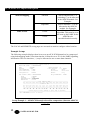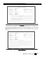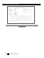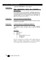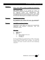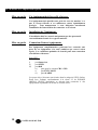
1
Dec 97 / Version 1.0
PCM/ADPCM Compression
Option: MXU9081C
Echo & Echo LANLink PCM/ADPCM
Compression Option
TECHNICAL:
SALES:
FAX:
ADDRESS:
WEB:
(0118) 965 6000
(0118) 965 5100
(0118) 965 5001
464 Basingstoke Road, Reading, Berkshire RG2 0QN
www.blackbox.co.uk
PCM/ADPCM Compression Option
How To Contact your Local Black Box
Italy:
Australia:
Black Box Italia S.P.A
Black Box Catalog Australia PTY LTD
Tel: 0227400280
Fax: 0227400219
Web Site: www.blackbox.it
Tel: 0398797100
Fax: 0398702955
Deutschland:
Brazil:
Black Box Deutschland
Black Box Do Brasil.
Tel: 0811/5541-0
Fax: 0811/5541-499
Web Site: www.blackbox-deutschland.com
Tel: (011) 5515-4000
Fax: (011) 5515-4002
Web Site: www.blackbox.com.br
Switzerland:
Canada:
Datacom Black Box Services AG
Black Box Canada Corp.
Tel: 0554517070
Fax: 0554517075
Web Site: www.black-box.ch
Tel: 0416-736-8000
Fax: 0416-736-7348
Web Site: www.blackbox.com
Netherlands:
Mexico:
Black Box Datacom BV
Black Box De Mexico S.A. de C.V
Tel: 03032417799
Fax: 0302414746
Web Site: www.blackbox.nl/
Tel: 05-420-0100
Fax: 05-420-0123
Web Site: www.blackbox.com.mx
Belgium:
Japan:
Black Box
Black Box Catalog
Tel: 027258550
Fax: 027259212
Web Site: www.blackbox.be
Tel: 03-3820-5011
Fax: 03-3820-5010
Web Site: www.blackbox.co.jp/
2
SALES: 0118 965 5100
PCM/ADPCM Compression Option
France:
U.S.A
Black Box Catalogue
Black Box Corporation
Tel: 0145606700
Fax: 0145606747
Web Site: www.blackbox.fr
Tel: 724-746-5500
Fax: 724-746-0746
Web Site: www.blackbox.com
Spain:
Chile
Black Box Comunicaciones S.A.
Black Box Chile
Tel: 34 91 663 0200
Fax: 34 91 661 84 35
Web Site: www.blackbox.es
Tel: 00 562 223 8811
Fax: 00 562 225 1002
Web Site: www.blackbox.cl
TECHNICAL: 0118 931 2233
3
PCM/ADPCM Compression Option
Echo
ADPCM Module
User Manual Supplement
WARNING - BEFORE INSTALLATION, PLEASE REFER
TO SAFETY INSTRUCTIONS IN APPENDIX A
Certified Compliant in the EC, when fitted in accordance with the installation instructions,
against the following directives/standards:
Low Voltage Directive (73/23/EEC and amendment 93/68/EEC)
EN60950
: 1992 (Safety)
Electromagnetic Compatibility directive (89/336/EEC and subsequent
amendments to date):
EN55022
EN50082-1
: 1994 (Emissions)
: 1992 (Immunity)
Telecommunications Terminal Equipment directive (91/263/EEC and
amendment 93/68/EEC) where indicated in approvals requirements section.
Contents
Contents...................................................................................................................... 4
00000000Introduction.................................................................................................. 6
4
SALES: 0118 965 5100
PCM/ADPCM Compression Option
Functional Overview.................................................................................................... 7
Mechanical Construction.................................................................................. 7
Use And Configuration................................................................................................ 9
PABX Connection............................................................................................. 9
ADPCM Configuration Display......................................................................... 9
ADPCM Timeslot Assignment........................................................................ 10
Timeslot 16 Assignment................................................................................. 11
ADPCM Parameters....................................................................................... 11
Example Set-ups............................................................................................ 12
Installation................................................................................................................. 15
ADPCM Module Installation............................................................................ 15
ADPCM Interface Cabling & Connections...................................................... 15
Internal Jumper Link....................................................................................... 15
Testing............................................................................................................ 15
Appendix 00000000A - Warnings0............................................................................ 16
Appendix B0000000 - Approval Requirements......................................................... 19
TECHNICAL: 0118 931 2233
5
PCM/ADPCM Compression Option
00000000Introduction
This User Manual Supplement describes the Installation, Operation and Use of the ECHO
ADPCM module, and must be read in conjunction with the ECHO Multiplexer User Manual.
The ECHO ADPCM module allows the ECHO multiplexer to take 30 channels of PCM
(G.711) voice, presented on the Drop & Insert (D&I) interface, and compress them down to
15 timeslots, each containing two four bit samples of 32k ADPCM (G.721).
For normal voice conversations, ADPCM (Adaptive Differential Pulse-Code Modulation)
provides voice quality that comparable to PCM digitised voice conversation.
Typical use of the ADPCM module is to interconnect two PABX systems. Even if the full 30
channels of PCM are selected, it still leaves 960Kbps of spare bandwidth free for data traffic.
Installation details for the ADPCM module are covered on page 15.
6
SALES: 0118 965 5100
PCM/ADPCM Compression Option
Functional Overview
The ADPCM module is a plug-in replacement for the Drop and Insert (D&I) card. It contains
30 bi-directional ADPCM compression units operating at 64K to 32K G.721 compression.
Each timeslot allocated to the ADPCM module maps to two compressed PCM timeslots,
determined by which mapping mode is selected. Two mapping modes, Alternate (see
Example a) and Sequential (see Example b), have been implemented to allow some
flexibility when assigning timeslots.
Timeslots may still be assigned to transparent Drop and Insert (D&I) as described in the
ECHO MULTIPLEXER User Manual as the ADPCM module incorporates all the functions
of the D&I card.
Both A-Law and u-Law PCM coding is available via soft configuration.
The ADPCM module is soft configured using the same configuration methods used for the
ECHO MULTIPLEXER. This is outlined in the ECHO MULTIPLEXER manual and in the
ADPCM Module Configuration section.
Mechanical Construction
The ADPCM module is built onto a single printed circuit board, which must be installed
inside the ECHO MULTIPLEXER enclosure.
TECHNICAL: 0118 931 2233
7
PCM/ADPCM Compression Option
8
SALES: 0118 965 5100
PCM/ADPCM Compression Option
Use And Configuration
This section only describes configuration of the ECHO ADPCM module. Configuration of
data channels is described in the USE AND CONFIGURATION section of the ECHO
MULTIPLEXER User Manual.
The ADPCM module options can be modified using the simple terminal configuration
process, described in the next section, similar to that for the ECHO MULTIPLEXER (If you
are not familiar with general configuration of the ECHO MULTIPLEXER, please refer to the
USE AND CONFIGURATION section of the ECHO MULTIPLEXER User Manual before
reading the following sections or attempting to configure the ADPCM module).
PABX Connection
The PABX may be connected to the ADPCM module using a European 120 Ohms RJ45 or
UK 75 Ohms 2 x BNC. The interface type must be selected using the internal jumper link
on the ADPCM module, before connecting the equipment.
ADPCM Configuration Display
If the ADPCM module has been fitted correctly the ECHO configuration screen will display
D&I Channels: 1 + ADPCM in the upper right area of the screen. The D&I/ADPCM
configuration display shown below is reached from any other page by locating the cursor
alongside this option, and then pressing return.
The same page for setting up the D&I card is also used for setting up the ADPCM module.
The current interface type (UK or EUR) is reported next to D&I Channel. Alongside this the
current status (SYNCHRONISED or NO CARRIER) of the D&I carrier signal is displayed.
The bandwidth allocated to the ADPCM module is displayed next to Drop Bandwidth. This
is updated as timeslots are added/removed from the main timeslot map.
TECHNICAL: 0118 931 2233
9
PCM/ADPCM Compression Option
2 MEGABIT E1 MULTIPLEXER
V1.04
============================ 12:04 16/09/97 ========================
Main Link (EUR) : SYNCHRONISED
Mode
: NORMAL
Nx64 Channels : 2
Framing
: CRC4
* D&I Channels : 1 + ADPCM
Idle Bandwidth
: 1984K
Alarms
: None
Clock Reference : LOOP
Statistics
: Main Link
Configuration
:>LOCAL
Events
: Log
D&I Channel (EUR): SYNCHRONISED
Drop Bandwidth: OFF
Mode
: NORMAL
Framing
: CRC4
ADPCM Mapping : Alternate
ADPCM Law
: A-Law
----------------------PCM TIMESLOT MAP------------------------S - - - - - - - - - - - - - - - - - - - - - - - - - - - - - - ------------------------TIMESLOT MAP--------------------------0 0 0 0 0 0 0 0 0 0 1 1 1 1 1 1 1 1 1 1 2 2 2 2 2 2 2 2 2 2 3 3
0 1 2 3 4 5 6 7 8 9 0 1 2 3 4 5 6 7 8 9 0 1 2 3 4 5 6 7 8 9 0 1
--------------------------------------------------------------S - - - - - - - - - - - - - - - - - - - - - - - - - - - - - - Cursor keys to move, CTRL-U to save, ESC to abandon
=====================================================================
Use <SPACEBAR>/<+>/<-> to select
D&I /ADPCM Configuration Page
ADPCM Timeslot Assignment
Timeslots are assigned by moving the cursor down to the TIMESLOT MAP section of the
D&I Channels screen.
Timeslots may be assigned directly by pressing the appropriate key on the
Supervisor port terminal keyboard e.g.:
Pressing:
1
2
3
4
D
A
-
assigns the slot to Nx64 Channel 1
assigns the slot to Nx64 Channel 2
assigns the slot to Nx64 Channel 3 (if fitted)
assigns the slot to Nx64 Channel 4 (if fitted)
assigns the slot to the D&I Channel
assigns the slot to the ADPCM module
un-assigns the timeslot
Unlike the other assignments, the ADPCM module may only be assigned to certain timeslots,
determined by the ADPCM Mapping. An attempt to allocate an invalid slot will be ignored.
Timeslots assigned to the ADPCM module will also highlight which PCM timeslots are being
assigned in the PCM TIMESLOT MAP above the main timeslot map, each PCM channel
being represented by a ‘P’. Note that each ADPCM assignment will map to two PCM
channels since it carries two compressed PCM samples.
Timeslots may also be assigned to transparent using the Drop and Insert (D&I) function as
described in the ECHO MULTIPLEXER User Manual. A ‘D’ in the PCM timeslot map
indicates that a channel is being transparently passed to the remote (i.e. no compression).
10
SALES: 0118 965 5100
PCM/ADPCM Compression Option
Timeslot 16 Assignment
For correct operation of the PABX signalling information, timeslot 16 must be passed
transparently to the remote PABX i.e. timeslot 16 must be assigned to ‘D’, drop and insert.
This is not done automatically, and must be set manually by the user if any voice channels are
to be used.
ADPCM Parameters
Locating the cursor alongside the entry in exactly the same manner as used on the
ECHO MULTIPLEXER accesses parameters for the ADPCM module.
To view the valid choices for the parameter, press the spacebar, + or - keys.
The choices by parameter are:
PARAMETER
CHOICES
NOTES
Mode
NORMAL
Normal run mode
LOCAL LOOP
D&I Port Loopback, causes
D&I to get carrier even when
not connected to link
REMOTE LOOP
Payload loopback, causes
data at D&I port to be echoed
back to the PABX
CRC4
16 Frame Synchronisation,
using CRC4 pattern, Allows
better link diagnostics
Non-CRC4
2 Frame Synchronisation
only.
Framing
TECHNICAL: 0118 931 2233
11
PCM/ADPCM Compression Option
ADPCM Mapping
ADPCM Law
Alternate
Allows odd timeslots 1-31
(excluding 17) to be allocated
to the ADPCM module. See
Examples
Sequential
Allows timeslots 1-15 to be
allocated to the ADPCM
module. See Examples
Affects the ADPCM
algorithm. This must be set to
the same as the PABX for the
ADPCM to be
encoded/decoded correctly.
A-Law
u-Law
The LOCAL and REMOTE set-up pages are accessed as usual to configure either location.
Example Set-ups
The following example displays show how to set-up all 30 PCM channels to be compressed
using both mapping modes. Note that timeslot 16 must be set to ‘D’ for the PABX signalling
information. The free timeslots (‘-‘) may be allocated to one or more data channels.
2 MEGABIT E1 MULTIPLEXER
V1.04
================================ 12:04 16/09/97 ===============================
Main Link (EUR) : SYNCHRONISED
Mode
: NORMAL
Nx64 Channels : 2
Framing
: CRC4
* D&I Channels : 1 + ADPCM
Idle Bandwidth
: 960K
Alarms
: None
Clock Reference : LOOP
Statistics
: Main Link
Configuration
:>LOCAL
Events
: Log
D&I Channel (EUR): SYNCHRONISED
Drop Bandwidth: 1024K
Mode
: NORMAL
Framing
: CRC4
ADPCM Mapping : Alternate
ADPCM Law
: A-Law
----------------------PCM TIMESLOT MAP------------------------S P P P P P P P P P P P P P P P D P P P P P P P P P P P P P P P
------------------------TIMESLOT MAP--------------------------0 0 0 0 0 0 0 0 0 0 1 1 1 1 1 1 1 1 1 1 2 2 2 2 2 2 2 2 2 2 3 3
0 1 2 3 4 5 6 7 8 9 0 1 2 3 4 5 6 7 8 9 0 1 2 3 4 5 6 7 8 9 0 1
--------------------------------------------------------------S A - A - A - A - A - A - A - A D - - A - A - A - A - A - A - A
Cursor keys to move, CTRL-U to save, ESC to abandon
==========================================================================
Use <SPACEBAR>/<+>/<-> to select
Set-up Example 1 – All 30 PCM channels selected for compression (Alternate ADPCM
Mapping)
12
SALES: 0118 965 5100
PCM/ADPCM Compression Option
2 MEGABIT E1 MULTIPLEXER
V1.04
================================ 12:04 16/09/97 ===============================
Main Link (EUR) : SYNCHRONISED
Mode
: NORMAL
Nx64 Channels : 2
Framing
: CRC4
* D&I Channels : 1 + ADPCM
Idle Bandwidth
: 960K
Alarms
: None
Clock Reference : LOOP
Statistics
: Main Link
Configuration
:>LOCAL
Events
: Log
D&I Channel (EUR): SYNCHRONISED
Drop Bandwidth: 1024K
Mode
: NORMAL
Framing
: CRC4
ADPCM Mapping : Sequential
ADPCM Law
: A-Law
----------------------PCM TIMESLOT MAP------------------------S P P P P P P P P P P P P P P P D P P P P P P P P P P P P P P P
------------------------TIMESLOT MAP--------------------------0 0 0 0 0 0 0 0 0 0 1 1 1 1 1 1 1 1 1 1 2 2 2 2 2 2 2 2 2 2 3 3
0 1 2 3 4 5 6 7 8 9 0 1 2 3 4 5 6 7 8 9 0 1 2 3 4 5 6 7 8 9 0 1
--------------------------------------------------------------S A A A A A A A A A A A A A A A D - - - - - - - - - - - - - - Cursor keys to move, CTRL-U to save, ESC to abandon
===============================================================================
Use <SPACEBAR>/<+>/<-> to select
Set-up Example 2 – All 30 PCM channels selected for compression (Sequential ADPCM
Mapping)
The following example displays show how to set-up PCM channels 1, 2, 20 and 21 to be
compressed using both mapping modes. Note that timeslot 16 must be set to ‘D’ for the
PABX signalling information. The free timeslots (‘-‘) may be allocated to one or more data
channels.
2 MEGABIT E1 MULTIPLEXER
V1.04
================================ 12:04 16/09/97 ===============================
Main Link (EUR) : SYNCHRONISED
Mode
: NORMAL
Nx64 Channels : 2
Framing
: CRC4
* D&I Channels : 1 + ADPCM
Idle Bandwidth
: 960K
Alarms
: None
Clock Reference : LOOP
Statistics
: Main Link
Configuration
:>LOCAL
Events
: Log
D&I Channel (EUR): SYNCHRONISED
Drop Bandwidth: 1024K
Mode
: NORMAL
Framing
: CRC4
ADPCM Mapping : Alternate
ADPCM Law
: A-Law
----------------------PCM TIMESLOT MAP------------------------S P P - - - - - - - - - - - - - D - - - P P - - - - - - - - - ------------------------TIMESLOT MAP--------------------------0 0 0 0 0 0 0 0 0 0 1 1 1 1 1 1 1 1 1 1 2 2 2 2 2 2 2 2 2 2 3 3
0 1 2 3 4 5 6 7 8 9 0 1 2 3 4 5 6 7 8 9 0 1 2 3 4 5 6 7 8 9 0 1
--------------------------------------------------------------S A - - - - - - - - - - - - - - D - - - - A - - - - - - - - - Cursor keys to move, CTRL-U to save, ESC to abandon
===============================================================================
Use <SPACEBAR>/<+>/<-> to select
Set-up Example 3 – PCM channels 1, 2, 20 and 21 selected for compression (Alternate
ADPCM Mapping)
TECHNICAL: 0118 931 2233
13
PCM/ADPCM Compression Option
2 MEGABIT E1 MULTIPLEXER
V1.04
================================ 12:04 16/09/97 ===============================
Main Link (EUR) : SYNCHRONISED
Mode
: NORMAL
Nx64 Channels : 2
Framing
: CRC4
* D&I Channels : 1 + ADPCM
Idle Bandwidth
: 960K
Alarms
: None
Clock Reference : LOOP
Statistics
: Main Link
Configuration
:>LOCAL
Events
: Log
D&I Channel (EUR): SYNCHRONISED
Drop Bandwidth: 1024K
Mode
: NORMAL
Framing
: CRC4
ADPCM Mapping : Sequential
ADPCM Law
: A-Law
----------------------PCM TIMESLOT MAP------------------------S P P - - - - - - - - - - - - - D - - - P P - - - - - - - - - ------------------------TIMESLOT MAP--------------------------0 0 0 0 0 0 0 0 0 0 1 1 1 1 1 1 1 1 1 1 2 2 2 2 2 2 2 2 2 2 3 3
0 1 2 3 4 5 6 7 8 9 0 1 2 3 4 5 6 7 8 9 0 1 2 3 4 5 6 7 8 9 0 1
--------------------------------------------------------------S A - - - - - - - - A - - - - - D - - - - - - - - - - - - - - Cursor keys to move, CTRL-U to save, ESC to abandon
===============================================================================
Use <SPACEBAR>/<+>/<-> to select
Set-up Example 4 – PCM channels 1, 2, 20 and 21 selected for compression (Sequential
ADPCM Mapping)
14
SALES: 0118 965 5100
PCM/ADPCM Compression Option
Installation
WARNING – Refer to Appendix A for Safety Instructions.
WARNING - The multiplexer must be disconnected from the power supply and all
peripheral connections before opening.
ADPCM Module Installation
With power turned OFF and DISCONNECTED, the screws on the left, right and top of the
multiplexer are removed using a No. 1 Pozidrive screwdriver to gain access to the interior of
the multiplexer. Remove the two screws from either side of the D&I port on the rear panel
of the unit. This will release the blanking plate or the D&I card (if fitted). The ADPCM
module plugs into connector J9 on the ECHO baseboard (replacing the D&I card if fitted).
The two screws should then be used to retain the module once fitted.
ADPCM Interface Cabling & Connections
Suitable connection may be arranged using an RJ45 connector (for European installations) or
BNC connectors (for UK installations) as described in the ECHO MULTIPLEXER User
Manual.
Internal Jumper Link
The internal jumper link on the ADPCM module must be set to the required interface type.
Fit to LK3 for European installations, LK4 for UK installations.
Testing
Replace the cover and screws before powering up the unit. Correct installation of the
ADPCM module may be confirmed by D&I Channels: 1 + ADPCM being displayed in the
upper right area of all ECHO configuration screens.
TECHNICAL: 0118 931 2233
15
PCM/ADPCM Compression Option
Appendix 00000000A - Warnings0
WARNING:
THIS EQUIPMENT
GROUNDED
MUST
BE
EARTHED
/
This equipment relies on the EARTH / GROUND connection to
ensure safe operation such that the user and TELECOM Network
are adequately protected. It must not under any circumstances be
operated without an earth connection, which could nullify its
approval for connection to a network.
WARNING:
INSTALLATION OF EQUIPMENT
Installation of this equipment must only be performed by suitably
trained service personnel.
WARNING:
CONNECTION OF OTHER EQUIPMENT
This equipment allows connection only of suitably approved
equipment to its ports, the safety status of which are defined
below.
SELV Ports:
i)
ii)
iii)
Supervisor port
MAIN port
D&I port
iv)
CH1 and CH2 (Channel ports)
v)
EXT CLOCK
vi)
ALARM port
The above named ports are classified as SELV (Safety Extra Low
Voltage) in accordance with in Clause 2.3 of EN60950 (BS7002,
IEC950 as applicable), and must only be connected to equipment
which similarly complies with the SELV safety classification.
16
SALES: 0118 965 5100
PCM/ADPCM Compression Option
Warnung:
Dieses Gerät Muß an einem Anschluß mit Schutzleiter
betrieben werden.
Zum sicheren Betrieb ist der Anschluß des Gerätes an
Spannungsversorgungen mit Schutzleiter notwendig. Nur so kann
ein
optimaler
Schutz
für
Bedienpersonal
und
Übertragungseinrichtungen gewährleistet werden. Unter keinen
Umständen darf dieses Gerät ohne Schutzleiter betrieben werden,
da ansonsten die Zulassung für den Anschluß an Netzen erlischt.
Warnung:
Installation des Gerätes
Die Installation des Gerätes darf nur von entsprechend
ausgebildetem und autorisiertem Personal durchgeführt werden.
Warnung:
Anschluß von anderen Geräten
Angeschlossen werden dürfen nur Systeme mit entsprechenden
zugelassenen und geeigneten Schnittstellen, siehe auch
nachfolgende Tabelle:
SELV Ports
i)
ii)
iii)
Supervisor port
MAIN port
D&I port
iv)
CH1 and CH2 (Channel ports)
v)
EXT CLOCK
vi)
ALARM port
Die oben aufgeführten Ports sind klassifiziert als SELV (Safety Extra
Low Voltage) in Übereinstimmung mit Absatz 2.3 der Verordnung
EN60950 (BS7002, IEC950 soweit anwendbar), und dürfen nur
zusammen mit Geräten verwendet werden, die dieser Bestimmung
entsprechen.
TECHNICAL: 0118 931 2233
17
PCM/ADPCM Compression Option
Mise en garde:
Cet équipement doit être relié a la terre
Cet équipement doit posséder une prise de terre de manière à ce
que le réseau télécom et ses utilisateurs soient équitablement
protégés. Tout manquement à cette obligation entraînerait
l'annulation de l'autorisation de connexion a un réseau.
Mise en garde:
Installation de l'équipment
L'installation doit être assurée uniquement par des personnels
convenablement formés à ce type de matériel.
Mise en garde:
Connexion d'autres équipements
Des équipement complémentaires pourrant être connectés aux
ports de cet équipement à la seule condition que ceux-ci soient
agrées. Les conditions optimales de sécurité pour toute connexion
sont définies ci-dessous:
Ports SELV.
i)
ii)
iii)
port Supervisor
port MAIN
port D&I
iv)
ports pour les canaux CH1 à CH2
v)
port EXT CLOCK
vi)
port ALARM
Les ports cités ci-dessous sont classés dans la catégorie SELV (Safety
Extra Low Voltage) conformément à la classe 2.3 de EN60950
(BS7002, IEC950 applicable) et doivent être connectés à des
équipements répondant à la norme de sécurité SELV.
18
SALES: 0118 965 5100
PCM/ADPCM Compression Option
Appendix B0000000 - Approval Requirements
The Echo MULTIPLEXER carrying the BABT / CE168 assessment symbols and approval
number, is approved for connection to the networks identified in this Appendix as follows:
G.703
In the UK, to PD7024 (75 Ohm Un-balanced) via 2 x BNC connectors. The internal link
must be set to the UK position, as detailed in the installation instructions.
Throughout Europe (Pan European) to CTR12 based on NET12 via RJ45 Connector (120
Ohms Balanced). The internal link must be set to the EUR position, as detailed in the
installation instructions.
TECHNICAL: 0118 931 2233
19