1
MaXiO series
System Manual
Please note that when you select the analog or S/PDIF input channels, the input signals from that
specific channel pair from the E.D.I or M.D.I multichannel ports are no longer used.
Please keep in mind that the M.D.I analog and S/PDIF input selection buttons should not be used if
you do not want to use the S/PDIF or analog input signals from the device or cable connected to the
M.D.I port – use them only when you are using the M.D.I breakout cable (S/PDIF inputs, no analog
inputs) or a M.D.I extension like the MaXiO 032 breakout box (both S/PDIF and analog inputs).
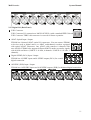
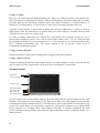
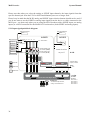
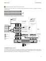
5.2.1 Input signal path block diagram
E.D.I Connector #2
E.D.I Connector #1
E.D.I 1
E.D.I 2
IN PORT1
M.D.I Connector
1/2
3/4
5/6
7/8
IN PORT2
8 ch. audio stream
M.D.I [1/4]
M.D.I [2/4]
M.D.I [3/4]
M.D.I [4/4]
S/PDIF IN
ANALOG IN
S
X X
A
X X
S
S
A
A A
Mono MIX
X X
S
Onboard S/PDIF Input
Ch. selection (CH3/4)
same structure
as port 1
Onboard Analog Input
Ch. selection (CH1/2)
z REC DMA
1/2/3/4/5/6/7/8 ch.
Total 32ch DMA
at (max.) 192kHz
z REC DMA
9/10/11/12/13/14/15/16 ch.
Monitor ON
To PC
X X Monitor OFF
1/2
3/4
5/6
7/8
9/10
11/12
13/14
Internal 64ch 32bit Digital Mixer
MASTER OUT
To Selected output Channel,
analog out and S/PDIF out
30
15/16
IN PORT3
IN PORT4
OUT PORT 1
OUT PORT 2
OUT PORT 3
OUT PORT 4