1
SPA Bus
Communication
Server
for Microsoft Windows
and InTouch Applications
User Manual
Ver 1.x Rev 2.3
DR120 10
DR120 11
KLINKMANN AUTOMATION
P.O. Box 38
FIN-00371 Helsinki Finland
tel. int. + 358 9 5404940
fax int. + 358 9 5413541
www.klinkmann.com
Klinkmann Automation SPA Bus Server
i
Table Of Contents
Overview ......................................................................................................................... 1
Communication Protocols ............................................................................................... 2
Accessing Remote Items via the SPA Server ................................................................. 3
Installing the SPA Bus Server ......................................................................................... 4
Installing the Server .................................................................................................. 4
Licensing by using HASP HL key ............................................................................. 7
Software license key ................................................................................................. 7
Transferring the software license to other computer ............................................. 8
Installing the I/O Server Infrastructure ...................................................................... 10
Configuring the SPA Server ............................................................................................ 10
Server Settings Command ........................................................................................ 10
Configure Communication Port Command ............................................................... 13
Saving SPA Configuration File .................................................................................. 14
Configuration File Location ....................................................................................... 15
Topic Definition Command........................................................................................ 15
Item Names ..................................................................................................................... 18
Monitoring and Controlling Communication with a SPA device ................................ 19
Item/Point Naming Examples.................................................................................... 20
SPA Server Unit Definition File ....................................................................................... 21
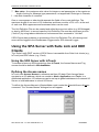
Using the SPA Server with Suite Link and DDE Clients .................................................. 22
Using the SPA Server with InTouch .......................................................................... 22
Defining the Access names ...................................................................................... 22
Defining the Tag Names ........................................................................................... 24
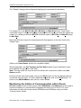
Monitoring the Status of Communication with InTouch ............................................. 26
Using the SPA Server with OPC Clients ......................................................................... 27
Configuring DCOM ................................................................................................... 27
Running SPA “OPC & DDE” version as Windows NT Service .................................. 29
Using the SPA with OPCLink Server ............................................................................... 30
OPCLink Topic Definition .......................................................................................... 30
Accessing SPA Items via the OPCLink Server ......................................................... 31
Notes on Using Microsoft Excel ...................................................................................... 32
Reading Values into Excel Spreadsheets ................................................................. 32
Writing Values to SPA Points.................................................................................... 32
Troubleshooting .............................................................................................................. 34
WIN.INI entries ......................................................................................................... 34
Troubleshooting menu .............................................................................................. 35
Internal Logger .......................................................................................................... 36
SPA Server Ver1.x User Manual Rev 2.3
120XXM23
Klinkmann Automation SPA Bus Server
1
SPA Bus
Communication Server
Overview
The SPA Bus Communication Server (hereafter referred to as the “SPA Server” or
“SPA” or “Server”) is a Microsoft Windows application program that acts as a
communication protocol server and allows other Windows application programs to access
to data from SPA bus devices. The SPA bus consists of one IBM PC or compatible
computer as a master and several slaves. The IBM PC is connected to the physical SPA
bus via serial communication using Bus Connection Module. For fibre optic connections
the SPA-ZC 22 unit can be used. The interface to Bus Connection Module can be RS485 (RTS lines must present) or RS-232. If RS-485 is used then RS-232/RS-485
converter (e.g., OPTO22 AC7A/B Adapter Card) or IBM serial adapter card (e.g.,
OPTO22 AC37 Remote Bus Adapter Card) can be used. The Server is also capable to
communicate with SACO 100M device. In this case there is no need for the RS2-32/RS485 converter.
There are two different SPA Server versions described in this manual:
- Server version (ordering number DR 120 10) supporting SuiteLink, FastDDE and DDE
protocols; this version hereafter is referred to as the “Suite Link & DDE” version.
- Server version (ordering number DR 120 11), supporting OPC and DDE protocols;
this version hereafter is referred to as the “OPC & DDE” version;
The separate installation package is supplied for each version of the Server. In all cases
the name of Server executable file is SPA.EXE. All further information in this manual is
same for all versions of the Server, with the exception of few points where communication
protocol specific features are explained.
SPA Server Ver 1.x User Manual Rev 2.3
120XXM23
Klinkmann Automation SPA Bus Server
2
Communication Protocols
Dynamic Data Exchange (DDE) is a communication protocol developed by Microsoft to
allow applications in the Windows environment to send/receive data and instructions
to/from each other. It implements a client-server relationship between two concurrently
running applications. The server application provides the data and accepts requests from
any other application interested in its data. Requesting applications are called clients.
Some applications such as Wonderware InTouch and Microsoft Excel can simultaneously
be both a client and a server.
FastDDE provides a means of packing many proprietary Wonderware DDE messages
into a single Microsoft DDE message. This packing improves efficiency and performance
by reducing the total number of DDE transactions required between a client and a server.
Although Wonderware's FastDDE has extended the usefulness of DDE for our industry,
this extension is being pushed to its performance constraints in distributed environments.
The SPA Server “Suite Link & DDE version” supports the FastDDE Version 3 -- an
extension to Wonderware’s proprietary FastDDE Version 2. This extension supports the
transfer of Value Time Quality (VTQ) information. The original DDE and FastDDE Version
2 formats are still supported, providing full backward compatibility with older DDE clients.
FastDDE Version 3 works on Windows 9x systems as well as Windows NT systems.
NetDDE extends the standard Windows DDE functionality to include communication over
local area networks and through serial ports. Network extensions are available to allow
DDE links between applications running on different computers connected via networks
or modems. For example, NetDDE supports DDE between applications running on IBM
compatible computers connected via LAN or modem and DDE-aware applications
running on non-PC based platforms under operating environments such as VMS and
UNIX.
SuiteLink uses a TCP/IP based protocol and is designed by Wonderware specifically to
meet industrial needs such as data integrity, high-throughput, and easier diagnostics.
This protocol standard is only supported on Microsoft Windows NT 4.0 or higher.
SuiteLink is not a replacement for DDE, FastDDE, or NetDDE. The protocol used
between a client and a server depends on your network connections and configurations.
SuiteLink was designed to be the industrial data network distribution standard and
provides the following features:
-
-
Value Time Quality (VTQ) places a time stamp and quality indicator on all data values
delivered to VTQ-aware clients.
Extensive diagnostics of the data throughput, server loading, computer resource
consumption, and network transport are made accessible through the Microsoft
Windows NT operating system Performance Monitor. This feature is critical for the
scheme and maintenance of distributed industrial networks.
Consistent high data volumes can be maintained between applications regardless if
the applications are on a single node or distributed over a large node count.
The network transport protocol is TCP/IP using Microsoft’s standard WinSock
interface.
OPC (OLE for Process Control) is an open interface standard to provide data from a data
source and communicate the data to any client application in a common standard way.
SPA Server Ver 1.x User Manual Rev 2.3
120XXM23
Klinkmann Automation SPA Bus Server
3
The OPC is based on Microsoft OLE, COM and DCOM technologies and enables simple
and standardised data interchange between the industrial or office sector and the
production sector. From general point of view many aspects of OPC are similar to DDE,
but main difference is in the implementation by using Microsoft's COM (Component
Object Model) technology. It enables fast exchange with process automation data and
OPC open interface allows access to data from OPC Server in same standard way from
OPC client applications supplied by different developers.
For more information on the basics of OPC, please refer to the OPC Specification. The
OPC Data Access Custom Interface Specification is maintained by OPC Foundation, the
current specification is 2.04 dated September 2000.
The OPC support for SPA Server “OPC & DDE” version is implemented based on
FactorySoft OPC Server Development Toolkit and it conforms to OPC Data Access
Custom Interface Specification 2.04. The SPA Server “OPC & DDE” version is tested for
compliance and is compatible with OPC Foundation OPC Data Access Compliance Test
Tool.
The Suite Link, FastDDE (Version 3) and DDE support for SPA Server “Suite Link &
DDE” version is implemented by Wonderware I/O Server Toolkit ver. 7.0 (060).
The FastDDE (Version 2) and DDE support for SPA Server “OPC & DDE” version is
implemented by Wonderware I/O Server Toolkit ver. 5.0 (008).
Accessing Remote Items via the SPA Server
The communication protocol addresses an element of data in a conversation that uses a
three-part naming convention that includes the application name, topic name and item
name. The following briefly describes each portion of this naming convention:
application name
The name of the Windows program (Server) that will be accessing the data element. In
the case of data coming from or going to SPA bus devices, the application portion of the
address is SPA.
topic name
Meaningful names are configured in the Server to identify specific devices. These names
are then used as the topic name in all conversations to that device. For example, spa02.
Note. You can define multiple topic names for the same device to poll different items at
different rates.
item name
Item is a specific data element within the specified topic. For the SPA Server, an item is
an individual point (Input, Output, Setting, Variable, Memory message) in the SPA bus
device (The item/point names are fixed by the SPA Server as described in the Item
Names section).
Note. In some cases, the term "point" is used interchangeably with the term "item".
SPA Server Ver 1.x User Manual Rev 2.3
120XXM23
Klinkmann Automation SPA Bus Server
4
Installing the SPA Bus Server
Installing the Server
The SPA Bus Server installation package is supplied as a Microsoft Installer file
DR12010_xxx.msi (for “Suite Link & DDE” version) or DR12011_xxx.msi (for “OPC & DDE”
version), where xxx is the current (latest) version of SPA Bus Server.
To install the SPA Server, run the DR12010_xxx.msi (for “Suite Link & DDE” version) or
DR12011_xxx.msi (for “OPC & DDE” version) and proceed as directed by the SPA Bus
Server Setup Wizard. The installation is simple and straightforward, only it is important to
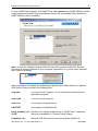
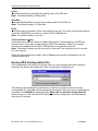
select the correct protection (HASP key or software license) in “Custom Setup” dialog:
The HASP key or software license key is needed for full time running of SPA Bus Server.
The HASP key is an USB key (dongle) to be installed into PC USB port and needs the
SafeNet Sentinel LDK Run-time Environment (HASP HL Runtime Package) to be
installed and running – see details in “Licensing by using HASP HL key” section below.
The software license key is a 16-character alphanumeric “computer-dependent” string,
provided after purchasing the SPA Bus Server (for more information, see “Software
license key” section below. Without HASP key installed or software license key entered,
the SPA Bus Server will run one hour in demo mode. After purchasing the SPA Bus
Server, the appropriate HASP key or software license key is provided and no reinstallation of SPA Bus Server is needed.
In case “HASP Device driver” and “HASP Files” are not selected then HASP USB key
will not be supported and only the software license will be available (files needed for
HASP USB key will not be installed):
SPA Server Ver 1.x User Manual Rev 2.3
120XXM23
Klinkmann Automation SPA Bus Server
5
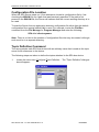
In case “HASP Device driver” and “HASP Files” are selected then HASP USB key will be
supported and both HASP-key and software license will be available (files needed for
HASP USB key will be installed):
Note: In case the SafeNet Sentinel LDK Run-time Environment (HASP HL Runtime
Package) is already installed on your computer (separately or by some other software)
then it can be disabled:
When installation is finished, the subdirectory specified as a folder where to install the
SPA Server files will contain the following files:
SPA.EXE
The SPA Server Program. This is a Microsoft Windows 32-bit
application program.
SPA.CHM
The SPA Server Help file.
SPA.CFG
An example configuration file.
UNIT.DEF
An example unit definition file.
hasp_windows_44
42.dll
Dynamic Link Library installed only if “HASP Files” is selected
during the installation in “Custom Setup” dialog.
haspdinst.exe
Sentinel LDK Run-time Environment Installer (HASP HL
SPA Server Ver 1.x User Manual Rev 2.3
120XXM23
Klinkmann Automation SPA Bus Server
6
Runtime Package), copied to SPA Server folder only if “HASP
Device driver” is selected during the installation in “Custom
Setup” dialog.
LICENSE.RTF
Klinkmann Automation software license file.
KLSERVER.DLL
Dynamic Link Library necessary for “OPC & DDE” version of
the Server.
WWDLG32.DLL
Dynamic Link Library necessary only for “OPC & DDE” version of
the Server.
In case the “HASP Device driver” is selected during the installation in “Custom Setup”
dialog, the Sentinel LDK Run-time Environment (HASP HL Runtime Package) is installed
during the SPA Server installation (and will be uninstalled during the SPA Bus Server
uninstallation). The presence of Sentinel LDK Run-time Environment can be checked
after the SPA Bus Server installation by looking-up in Control Panel / Administrative Tools
Services – the Service “Sentinel Local License Manager” must be started.
Notes:
1. The SPA Bus Server “Suite Link & DDE” version is developed with Wonderware I/O
Server Toolkit (ver 7,2,1,6) and needs the Wonderware FS 2000 Common
Components to be installed on computer where the SPA Server is running. If using
Wonderware InTouch 8.0 or newer, install the FS 2000 Common Components before
installing InTouch (see also Wonderware Tech Notes 404 and 313). The Wonderware
FS2000 Common Components are installed automatically when any of Wonderware
product (e.g. InTouch or some Wonderware I/O server) is installed.
2. If SPA Bus Server “Suite Link & DDE” version will run on PC where Wonderware
FS2000 Common Components are not installed then a special I/O Server Infrastructure
installation package can be obtained from Klinkmann Automation (see Installing the
I/O Server Infrastructure section below). This I/O Server Infrastructure installation
package contains the minimum set of software needed to run the SPA Bus Server and
these infrastructure files must be install prior to executing the SPA Bus Server.The I/O
Server Infrastructure does not support using SPA Bus Server as a Windows Service
and remote access to SPA Bus Server (when DDE/SuiteLink Client is not located on
same computer as SPA Bus Server).
To uninstall the SPA Bus Server, start Control Panel, select “Uninstall a program”
(“Add/Remove Programs” on XP/2003) and select the “ABB SPA Bus SuiteLink and DDE
Server” or “ABB SPA Bus OPC and DDE Server” from the list of available software
products. Click on “Uninstall” (“Add/Remove…” on XP/2003) and proceed as directed by
the Uninstall Wizard.
SPA Server Ver 1.x User Manual Rev 2.3
120XXM23
Klinkmann Automation SPA Bus Server
7
Licensing by using HASP HL key
The following should be done to enable the licensing by HASP HL key:
-
-
-
The “HASP Device driver” and “HASP Files” are selected during the SPA Bus
Server installation in “Custom Setup” dialog – that causes correspondingly
haspdinst.exe and hasp_windows_4442.dll files are copied to SPA Bus Server
folder and Sentinel LDK Run-time Environment (HASP HL Runtime Package) is
installed and started, enabling the SPA Bus Server can detect the HASP HL USB
dongle;
insert the received HASP key into USB port, and wait until “Installing device driver
software” message disappears and “Device driver software installed successfully”
message appears;
start SPA Bus Server and check - if “Sofware key or HASP HL key not found!”
message does not appear then it means everything is done correctly and SPA Bus
Server runs in full mode with licensing by HASP HL key enabled.
Software license key
SPA Bus Server supports the “computer dependent” software licensing. The following
steps are required to enable it:
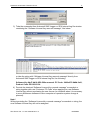
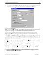
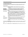
1) Start SPA Bus Server, click on "Help" menu item (also short-cut Alt+H can be used)
and pop-up menu with "Help" menu commands will appear:
Select “License” and “License” dialog will appear:
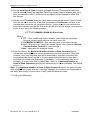
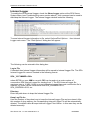
2) Here the “Customer PC Code” is “computer-dependent” string generated by SPA Bus
Server and it is unique for this computer. Write it down or Copy/Paste to e-mail when
ordering the SPA Bus Server.
3) After purchasing the SPA Bus Server, you will get the software license key - 16character alphanumeric string. Open the “License” dialog again and Copy/Paste it to
“Software Key” field:
SPA Server Ver 1.x User Manual Rev 2.3
120XXM23
Klinkmann Automation SPA Bus Server
8
4) Click OK and restart SPA Bus Server. SPA Bus Server software license now is
enabled.
Note – the “Software Key” string is saved to MS Windows system directory (e.g.
C:\Windows) WIN.INI file [SPA] section to enable it is automatically detected at SPA Bus
Server next start-up.
Transferring the software license to other computer
The transfer of Software License Key might be needed in very rare situations when it is
necessary to move Klinkmann software to other computer (or operation system change is
planned for same computer). Such transfer PERMANENTLY removes the Software
License Key, so be very careful when deciding to use this option.
The following steps are required to transfer the Software License Key:
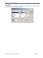
1) Start the SPA Bus Server. For SPA Bus Server “Suite Link & DDE” version, the
ArchestrA SMC Log Viewer (or Wonderware Logger) must be started. For SPA
Bus Server “OPC & DDE” version, the SPA Internal Logger and “Log to File”
should be enabled (see “Troubleshooting menu” and “Internal Logger”sections at
the end of this manual). Select Help/License from main menu and click the
“Transfer” button on “License” dialog:
2) Confirm the transfer of Software License Key by clicking on Yes button:
The “License” dialog now will contain the empty “Customer PC Code” and
“Software Key” fields:
SPA Server Ver 1.x User Manual Rev 2.3
120XXM23
Klinkmann Automation SPA Bus Server
9
3) Take the screenshot from ArchestrA SMC Logger or SPA Internal Log file window
containing the “Software License Key removal message”, like below:
or take the string with “Software License Key removal message” directly from
ArchestrA SMC Logger or SPA Internal Log file, like following:
Software Key 6dd7-4b19-8f20-500e removed. PC Code: 2496-a075-8b8b-3a91,
Product Code: DR12010 124
4) Provide the obtained “Software License Key removal message” screenshot or
string together with new “Customer PC Code” when applying for new Software
License Key without purchasing the new license (in situations when it is necessary
to move Klinkmann software to other computer or operation system change is
planned).
Note!
Without providing the “Software License Key removal message” screenshot or string, the
new Software License Key will not be assigned.
SPA Server Ver 1.x User Manual Rev 2.3
120XXM23
Klinkmann Automation SPA Bus Server
10
Installing the I/O Server Infrastructure
The I/O Server Infrastructure installation package is supplied as a self-extracting archive
(IOServerInfrastructure.exe) and can be downloaded from Klinkmann’s web site.
To install the I/O Server Infrastructure from the self-extracting archive, run the
IOServerInfrastructure.exe and proceed as directed by the I/O Server Infrastructure
Setup program.
To uninstall the I/O Server Infrastructure, start Control Panel, select “Add/Remove
Programs” and select the “IO Server Infrastructure” from the list of available software
products. Click on “Add/Remove…” and proceed as directed by the UnInstallShield
program.
Note: The I/O Server Infrastructure installation will be rejected if Wonderware FS2000
Common Components are already installed on same computer. The I/O Server
Infrastructure does not support using SPA Server as a Windows Service and remote
access to SPA Bus Server (when DDE/SuiteLink Client is not located on same computer
as SPA Bus Server).
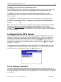
Configuring the SPA Server
After the SPA Server is initially installed, a small amount of configuration is required.
Configuring the Server automatically creates a SPA.CFG file, which holds all the topic
definitions, entered, as well as the communication port configurations. This file will
automatically be placed in the same directory in which SPA.EXE is located unless the
path where the configuration file will be placed is a specified by the /Configure/Server
Settings… command.
To perform the required configurations, start up the SPA. If the Server starts up as an
icon, double-click on the icon to open the server's window. To access the commands
used for the various configurations, open the /Configure menu:
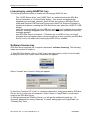
Server Settings Command
A number of parameters that control the internal operation of the Server can be set. In
most cases, the default settings for these parameters provide a good performance and do
not require changing. However, they can be changed to fine-tune the Server for a specific
environment.
SPA Server Ver 1.x User Manual Rev 2.3
120XXM23
Klinkmann Automation SPA Bus Server
11
To change the Server's internal parameters, invoke the /Configure/Server Settings...
command. The "Server Settings" dialogue box will appear:
The following describes each field in this dialogue box:
Protocol Timer Tick
This field is used to change the frequency at which the Server checks for work to do. This
should be approximately 2 to 4 times the fastest rate desired to update data from the SPA
bus devices.
NetDDE being used
Select this option if you are in network using NetDDE.
Configuration File Directory
The first field is used to specify the path (disk drive and directory) in which SPA will save
its current configuration file. SPA will use this path to load the configuration file the next
time it is started.
Notes.
1. Only the "path" may be modified with this field. The configuration file is always named
SPA.CFG.
2. There is no limit to the number of configuration files created, although each must be in
a separate directory. When using the SPA Server with InTouch, it is a good practice
to place the configuration file in the application directory.
Retry failed write messages indefinitely
This field is used to disable the deleting of pending write messages when slow poll mode
on some topic is started. As default all write messages for this topic are deleted when
topic enters the slow poll mode.
Note. Be careful when using this setting if SPA device is switched off, but client
application continues to generate new values to be written to this device -- it can cause
the computer memory overload with memory allocated for write messages.
Start automatically as Windows NT Service
Enabling this option will cause the SPA Server “Suite Link & DDE” version to start as a
Windows NT service.
Windows NT offers the capability of running applications even when a user is not logged
on to the system. This is valuable when systems must operate in an unattended mode.
Enabling this option and rebooting the system will cause the Server to run as a Windows
SPA Server Ver 1.x User Manual Rev 2.3
120XXM23
Klinkmann Automation SPA Bus Server
12
NT service. However, to view configuration information or to reconfigure the Server, the
user must log on to the system. Any Server related problems that may arise such as
missing adapter cards, licensing failures or device drivers not loading will not be visible to
the user until a log on is performed. Disabling this option and rebooting the system will
cause the Server to run as a Windows NT application program once again.
Notes.
1. The Start automatically as Windows NT Service feature can be activated only with
SPA Server “Suite Link & DDE” version. To start the SPA Server “OPC & DDE”
version as Windows NT Service, refer to Running SPA “OPC & DDE” version as
Windows NT Service section of this manual.
2. The Service Startup configuration can be changed by MS Windows NT Control
Panel/Services configuration dialogs. The Allow Service to Interact with Desktop
checkbox in “Service” dialogue box must be checked (the “Service” dialogue box can
be invoked by pressing the Startup… button on “Services” dialogue box when Service
SPA_IOServer is selected). If Allow Service to Interact with Desktop is not
selected then SPA Server full functionality is not ensured (e.g. the Server
configuration can not be changed, no message boxes will be displayed, etc.).
When all entries have been made, click on OK.
SPA Server Ver 1.x User Manual Rev 2.3
120XXM23
Klinkmann Automation SPA Bus Server
13
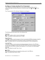
Configure Communication Port Command
This command is used to configure the communication port that will be used to
communicate with the SPA bus devices. Invoke the menu item /Configure/Com Port
Settings...
The "Communication Port Settings" dialogue box will appear:
The following describes each field in this dialogue box:
Com Port
This field is used to select a communication port.
Note. The default Communication port is COM1.
Reply Timeout
This field is used to enter the amount of time (in seconds) all SPA bus devices using the
selected communication port will be given to reply to commands from the Server.
Note. The default value of 3 seconds should be sufficient for most configurations.
Line Idle Time
This field is used to enter the delay time between the last character of the SPA bus
devices reply messages and the start of the SPA DDE Server next message, this gives
more time for the devices' software and hardware to turn around from transmitting to
receiving.
Note. The default Line Idle Time is 5 ms.
Baud Rate
The selected Baud Rate must match the setting used in the SPA bus.
Note. The default Baud Rate is 9600.
SPA Server Ver 1.x User Manual Rev 2.3
120XXM23
Klinkmann Automation SPA Bus Server
14
Parity
The selected Parity must match the setting used in the SPA bus.
Note. The default setting is Even parity.
Data Bits
The selected Data Bits must match the setting used in the SPA bus.
Note. The default setting is 7 Data Bits.
Echo
This field must be checked if echo comes back to the port. The echo can be generated by
some RS-232/RS-485 converters or by the SACO 100M device.
Note. The default setting is no echo.
Time and Date sending
These fields are used to enable or disable Date and/or Time transfers to all SPA bus
devices and to enter the intervals between Date/Time transfers. Date/Time transfer
should not be enabled if the SACO 100M device is connected to this port.
Note. The default settings are 60 seconds for Date and Time transfers and 10 seconds
for Time transfer.
When all entries have been made, click on Done to process the configuration for the
communication port.
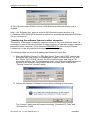
Saving SPA Configuration File
If the configuration file does not currently exist, or a new configuration path has been
specified, the Server will display the "Save Configuration" dialogue box:
This dialogue box displays the path where the Server is going to save the current
configuration file. The path may be changed if necessary. Also, the path can optionally be
recorded in the WIN.INI file by selecting the Make this the default configuration file
option. Doing so it will allow the SPA Server to find the configuration file automatically
each time it is started.
SPA Server Ver 1.x User Manual Rev 2.3
120XXM23
Klinkmann Automation SPA Bus Server
15
Configuration File Location
When the SPA Server starts up, it first attempts to locate its configuration file by, first
checking the WIN.INI file for a path that was previously specified. If the path is not
present in the WIN.INI file, the Server will assume that the current working directory is to
be used.
To start the Server from an application directory configuration file other than the default
configuration file a special switch (/d:) is used. For example, invoke the File/Run
command from the File Manager or Program Manager and enter the following:
SPA /d:c:\directoryname
Note. There is no limit to the number of configuration files that may be created, although
each must be in a separate directory.
Topic Definition Command
The user provides each SPA bus device with an arbitrary name that is used as the topic
name for all references to the device.
The following steps are taken to define the topics attached to the SPA bus device:
1.
Invoke the menu item /Configure/Topic Definition… The "Topic Definition" dialogue
box will appear:
SPA Server Ver 1.x User Manual Rev 2.3
120XXM23
Klinkmann Automation SPA Bus Server
2.
16
To modify an existing topic, select the topic name and click on Modify. To define a
new topic, click on New. The "Topic Definition" dialogue box will appear:
3. Enter the Topic Name.
Note: If using InTouch the same Topic Name is to be entered in the "Add Access Name"
dialogue box described in the Using the SPA Server with InTouch section.
4. Click on the ComPort button to associate a communication port with the topic.
Note: Additional topics may be associated with the same communication port later.
5. Select the corresponding SPA Device. These devices (units) should be defined in the
Unit Definition File. For details see the SPA Server Unit Definition File section.
Note: There must be at least one SPA unit defined in the SPA Server Unit Definition File,
otherwise the SPA Server will not work.
6. Enter a unique, same as set on connected SPA device, Station Number. The range
of Station Number is 0…999, except 900.
7. Set the Update Interval field to indicate the frequency (in milliseconds) the items on
this topic will be read (polled). The default value is 1000 milliseconds.
8. Check or uncheck the Poll Events checkbox. If Poll Events checkbox is checked
then events of this Station are requested (polled) at event Update Interval. If this
checkbox is not checked then no event polling is performed.
9. Set the event Update Interval field to indicate the frequency (in milliseconds) the
events will be polled from this Station.
SPA Server Ver 1.x User Manual Rev 2.3
120XXM23
Klinkmann Automation SPA Bus Server
17
10. Set the Send Date & Time to enable or disable Date and Time transfers and enter
interval between Date/Time transfers. Date/Time transfer may be enabled only if the
topic corresponds to SACO 100M device and should not be enabled for other SPA
bus devices.
11. Set the event File Name. Enter file name where events will be saved. Several topics
may use the same event file. If this field is left blank or Poll Events checkbox is not
checked then events are not recorded to the file. If some event is received then this
event data is written into the file. Events are stored as character strings, each event is
stored in one row in the following format:
P TTT YYYY/MM/DD HH:MM:SS Event Value
Where:
P TTT -- Port number and Station Number; these fields are necessary
because several topics may use the same event file;
YYYY/MM/DD HH:MM:SS -- date and time when event was received;
Event -- received event; event can contain its own time; (Refer to SPA bus
Communication Protocol for event formats.)
Value – data value for analogue events.
12. Enter the value in the Maximum Number of Items in Read Command field to
indicate how many data items can be requested in one read command. If this field
contains 1 then only one data item will be requested by one read command; this
choice should be used if request of several consecutive data items in one read
command can cause error responses (for example, if some requested data is not
available). If value in this field is greater than 1 then up to Maximum Number of
Items in Read Command items will be requested by one read command. The default
value is 1.
Note. If the Maximum Number of Items in Read Command value is too great for given
SPA device (Station reply with error message "Message from master too complicated for
the slave" and quality of some values is bad), then decrease this value.
13. Click on the Ok button.
SPA Server Ver 1.x User Manual Rev 2.3
120XXM23
Klinkmann Automation SPA Bus Server
18
Item Names
The SPA Server uses an item/point naming convention, based on the format of SPA bus
master messages. The SPA Server item names also must fit inside the range of data
categories and bus codes defined in the SPA Server Unit Definition File (see SPA Server
Unit Definition File section below) for the appropriate unit (device). The Unit Definition
File is read at SPA Server start-up and all item names are checked for correspondence
with data defined in the Unit Definition File, i.e. if item does not match with information
included in the Unit Definition File then item is rejected even if the item name syntax is
correct.
The item names used in the SPA Server generally may be described as:
DTc.m:p
where:
D -- Data category. Possible values for data category can be:
I, i
-- Input
O, o
-- Output
S, s
-- Setting
V, v
-- Variable
M, m
-- Memory
T – Data Type of item. Possible values can be:
D, d
-- Discrete, values: 0, 1;
I, i
-- Integer, value range: --2147483648 ... +2147483647;
R, r
-- Real, value range: --9999999999. 9999999999 ...
+9999999999.9999999999;
M, m
-- Message, maximal length 131 bytes, can contain ASCII characters
(from 0x20 to 0x7E) except CR (0x0D), LF (0x0A), ">", "<", ":", "/" and
"&";
c -- channel number, value can be 0 ... 999;
m -- data number, value can be 1 ... 999999;
:p -- optionally suffix to indicate the precision of data for write commands. The p value
can be from 0 to 10 and if item name does not contain the suffix :p then default value is 2
for Real items and 0 for Integer items. All unnecessared 0-digits and decimal point will be
removed from write command. If necessary the data value will be rounded.
For Reals the precision is the number of digits after decimal point, e.g., if value to write is
123.123456 and precision is :4 then the write command will contain the value 123.1235. If
value to write is 0.01034 and precision is :3 then the write command will contain the value
0.01 and if precision is :0 then only integer part of value will be written.
For Integers the precision can be used if the number of leading zeroes has some
importance for the slave. In this case the precision is the number of data value digits in
the write command including leading zeroes, e.g., if value to write is 123 and precision is
:5 then the write command will contain the value 00123. The precision is effective only for
positive (value equal or greater than zero) integer values.
SPA Server Ver 1.x User Manual Rev 2.3
120XXM23
Klinkmann Automation SPA Bus Server
19
There are also following additional items:
F, f
An
-- Slave identification code, Message;
-- Alarms, Message, Read Only, where n is a channel number, n value
can be 0 ... 999. These items are used for requesting the current
alarms for the channel.
Supported data categories, the range of channels, data numbers and value limits depend
on SPA unit (device) associated with the topic. To know which channels and bus codes
(i.e., data categories and data numbers) are supported by specific SPA unit (device),
refer the documentation of SPA unit (device). These parameters must be described in the
SPA Server Unit Definition File. For details see SPA Server Unit Definition File section.
Monitoring and Controlling Communication with a SPA device
For each topic, there are following build-in items offered by SPA Server to monitor and
control the communication with SPA device.
STATUS
For each topic, there is a built-in discrete item that indicates the state of communication
with device. The discrete item STATUS is set to 0 when communication fails and set to 1
when communication is successful. The STATUS value is set to 0 after 3 consecutive
unsuccessful retries to communicate with this device.
From InTouch the state of communication may be read by defining an I/O Discrete
tagname and associating it with the topic configured for the device and using STATUS as
the item name.
From Excel, the status of the communication may be read by entering the following
formula in a cell:
=SPA|topic!STATUS
UPDATEINTERVAL
The UPDATEINTERVAL item is an Integer type Read/Write item used to access the
currently set Update Interval (see Topic Definition Command section). It indicates the
current requested update interval (in milliseconds). The value of this item can be read
through DDE, Suite Link or OPC. Client can poke new values to this item. The range of
valid values is from 10 to 2147483647 milliseconds.
MAXINTERVAL
The MAXINTERVAL item is an Integer type Read Only item used to access the
measured maximum update interval (in milliseconds) of all items for the corresponding
topic for the last completed poll cycle. The range of valid values is from 0 to 2147483647
milliseconds.
The UPDATEINTERVAL and MAXINTERVAL items can be used to tune the
performance of communication.
ITEMCOUNT
SPA Server Ver 1.x User Manual Rev 2.3
120XXM23
Klinkmann Automation SPA Bus Server
20
The ITEMCOUNT item is an Integer type Read Only item used to access the number of
active items in the corresponding topic. The range of valid values is from 0 to
2147483647.
ERRORCOUNT
The ERRORCOUNT item is an Integer type Read Only item used to access the number
of active items with errors in the corresponding topic. The range of valid values is from 0
to 2147483647.
ERRORITEMS
The ERRORITEMS item is an Integer type Read/Write Only (unique for each topic) used
to access the total number of items with invalid item names (these items are rejected by
Server) and items with valid names but with non-existing address in SPA device. The
ERRORITEMS value can be reseted by writing 0 to this item. The range of valid values is
from 0 to 2147483647.
WRITECOUNT
The WRITECOUNT item is an Integer type Read Only item used to access the number of
write commands (messages) waiting for execution. The range of valid values is from 0 to
2147483647.
For example, in following way the WRITECOUNT item can be used to avoid the
increasing of memory occupied by not executed write commands:
- activate the hot link with WRITECOUNT item and start to monitor it;
- activate new write command (by poking new value) only if value of WRITECOUNT
becomes equal to 0, e.g., all previous write commands are executed and memory
occupied by them is freed.
SUSPEND
Special Read/Write Discrete Item SUSPEND may be used to control the communication
with a separate topic. If application changes SUSPEND value from 0 to 1 then
communication with topic is suspended. If SUSPEND value is changed back to 0 then
communication with this topic is resumed.
Note: If topic is suspended by setting SUSPEND value to 1, then Server rejects all new
write values to this topic, i.e., no new write messages are created after SUSPEND value
has changed from 0 to 1.
Item/Point Naming Examples
The following examples show the valid item names:
ID0.1
-- Discrete input 1, channel 0;
OR6.90 -- Real output 90, channel 6;
SD999.5 -- Discrete setting 5, channel 999;
SR1.5:3 -- Real setting 5, channel 1, precision 3;
VI455.999999
-- Integer variable 999999, channel 455;
MM85.154-- Message type memory item 154, channel 85;
F
-- Slave identification code;
A0
-- Alarms from channel 0;
STATUS -- Communication status.
SPA Server Ver 1.x User Manual Rev 2.3
120XXM23
Klinkmann Automation SPA Bus Server
21
The following examples show the invalid item names:
ID2.0, SI2.0, MM2.1000000
OI1000.2, VD1203.2, A2001
IU0.16, Md2.8, Sr10.1
d110, w183, l10, U22, m001
-- Data number is out of range;
-- Channel number is out of range;
-- Invalid data type;
-- Invalid data category.
SPA Server Unit Definition File
The SPA Server Unit Definition File (file name Unit.def) contains the list of supported
SPA units, available data categories and bus codes for each unit. This file will be read at
Server startup. This file should be located in the same directory as the SPA Server
configuration file.The general format of the Unit Definition File is the following:
{SPA unit} comment
[Data category] comment
Name Access rights Data Type Min value Max value !comment
The following describes each field in this file.
{SPA unit}
The definition of SPA unit. Unit names defined inside {} will be displayed as a selectable
SPA device names at topic configuration time. One unit definition can be common for
several data category definitions. The maximal length of SPA unit name is 16 characters.
[Data category]
The definition of data category. The cata category must be one character (a...z, both
uppercase and lowercase letters can be used). One data category definition can be
common for several bus code definitions.
Bus code definition
The parameter definition contains 7 data fields and optional comment field:
1. Name - the bus code; it consists of data category character and data number (from 1
to 3 digits, leading zeros allowed);
2. Access rights - the access rights of bus code:
r - Read Only;
w - Write Only;
r/w - Read and Write;
3. Data type:
disc - Discrete;
int - Integer;
real - Real;
string - Message;
4. Min channel - the minimum number of channel;
5. Max channel - the maximum number of channel;
6. Min value - the minimum write value for integer or real parameters; not supported if
Data type is Discrete or Message;
SPA Server Ver 1.x User Manual Rev 2.3
120XXM23
Klinkmann Automation SPA Bus Server
22
7. Max value - the maximum write value for integer or real parameters or the maximum
length of string for Message type parameters; not supported if Data type is Discrete;
! -- the start character of comment.
One or more spaces or tabs should separate the fields of bus code definition. The
maximum length of one row is 125 characters and there must be <CR> <LF> at the end
of each row. Both uppercase and lowercase letters can be used.
The Unit Definition File can be created and edited by some text editor (e.g. MS Notepad)
or also by MS Excel. In second case the Unit Definition File must be saved as a text file
(“Unit.txt”) by using tabs as delimiters of columns and then renamed to “Unit.def”.
If SPA Server has problems on processing of the Unit Definition File, all warnings and
errors will be logged to the Wonderware Logger and/or SPA Internal Logger.
Using the SPA Server with Suite Link and DDE
Clients
The “Suite Link & DDE” version of SPA Server is accessible from Suite Link clients (e.g.,
InTouch) and DDE clients (e.g., Excel).
Using the SPA Server with InTouch
To access to items on SPA bus devices from InTouch, the Access Names and Tag
names should be defined in WindowMaker.
Defining the Access names
InTouch uses Access Names to reference real-time I/O data. Each Access Name
equates to an I/O address, which can contain a Node, Application, and Topic. In a
distributed application, I/O references can be set up as global addresses to a network I/O
Server or local addresses to a local I/O Server.
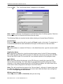
To define the Access Names in WindowMaker node invoke the /Special/Access Names...
command. The "Access Names" dialogue box will appear.
SPA Server Ver 1.x User Manual Rev 2.3
120XXM23
Klinkmann Automation SPA Bus Server
23
Click on Add…. The "Add Access Name" dialogue box will appear:
Note. If Add is selected, this dialogue box will be blank when it initially appears. Data has
been entered here to illustrate the entries that are made.
The following fields are required entries when entering an Access Name Definition:
Access Name
Enter an arbitrary name that will be used by InTouch to refer to the topic. For simplicity, it
is recommended that the name defined for the topic in SPA also be to be used here.
Node Name
If the data resides in a network I/O Server, in the Node Name box, type the remote node's
name.
Application Name
In the Application Name box, type the actual program name for the I/O Server program
from which the data values will be acquired. In case the values are coming from the SPA
Server the SPA is used. Do not enter the .exe extension portion of the program name.
Topic Name
Enter the name defined for the topic in the SPA Server to identify the topic the SPA
Server will be accessing. The Topic Name is an application-specific sub-group of data
elements. In the case of data coming from a SPA Server program, the topic name is the
exact same name configured for the topic in the SPA Server.
Note: This will usually be the same as the "Access Name", although, if desired, they may
be different. However, it must be the same name used when the topics were configured
in section Configuring the SPA Server.
Which protocol to use
Select the protocol (DDE or SuiteLink) that you are using.
SPA Server Ver 1.x User Manual Rev 2.3
120XXM23
Klinkmann Automation SPA Bus Server
24
When to advise server
Select Advise all items if you want the Server program to poll for all data whether or not
it is in visible windows, alarmed, logged, trended or used in a script. Selecting this option
will impact performance, therefore its use is not recommended.
Select Advise only active items if you want the Server program to poll only points in
visible windows and points that are alarmed, logged, trended or used in any script.
Click OK to accept the new Access Name and close the “Add Access Name” dialogue
box. The “Access Names” dialogue box will reappear displaying the new Access Name
selected in the list.
Click Close to close the “Access Names” dialogue box.
Defining the Tag Names
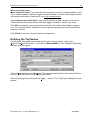
To define the Tag names associated with the new "Access Name", invoke the
/Special/Tagname Dictionary... command (in WindowMaker). The "Tagname Dictionary "
dialogue box will appear:
Click on New and enter the Tagname. (The tagname defined here is the name InTouch
will use. The SPA Server does not see this name.)
Select the tag type by clicking on the Type: … button. The "Tag Types" dialogue box will
appear:
SPA Server Ver 1.x User Manual Rev 2.3
120XXM23
Klinkmann Automation SPA Bus Server
25
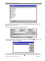
To access SPA device items, the type must be I/O Discrete, I/O Integer, I/O Real or I/O
Message. Select the Tag type.
The "Details" dialogue box for the tagname will appear:
Select the Access name for SPA Server by clicking on the Access Name: … button. The
"Access Names" dialogue box will appear:
Select the appropriate Access Name and click on Close. (If the Access Name has not
been defined as previously described, click on Add… and define the Access Name now.)
SPA Server Ver 1.x User Manual Rev 2.3
120XXM23
Klinkmann Automation SPA Bus Server
26
The "Details" dialogue box will appear displaying the selected Access Name:
For integers fill in the Min EU, Max EU, Min Raw and Max Raw fields. These fields
control the range of values that will be accepted from the Server and how the values are
scaled. If no scaling is desired, Min EU should be equal to Min Raw and Max EU equal
to Max Raw.
Enter the SPA item name to be associated with this tagname in the Item: field in the
"Details" box:
(Refer to the Item Names section for complete details.)
Where applicable, the Use Tagname as Item Name option may be selected to enter
automatically the tag name in this field.
Note: The tag name can only be used if it follows the conventions listed in the Item
Names section.
Once all entries have been made, click on the Save button (in the top dialogue box) to
accept the new tag name. To define additional tagnames click on the New button. To
return to the WindowMaker main screen, select Close.
Monitoring the Status of Communication with InTouch
InTouch supports built-in topic names called DDEStatus and IOStatus that are used to
monitor the status of communications between the Server and InTouch. For more
information on the built-in topic names DDEStatus and IOStatus, see your online
“InTouch User’s Guide”.
SPA Server Ver 1.x User Manual Rev 2.3
120XXM23
Klinkmann Automation SPA Bus Server
27
The status of communication between the Server and InTouch can be read into Excel by
entering the following DDE reference formula in a cell on a spreadsheet (in following
examples spa02 is the Topic Name configured for SPA Server):
=view|DDEStatus!spa02
or
=view|IOStatus!spa02
Using the SPA Server with OPC Clients
The “OPC & DDE” version of SPA Server is accessible from OPC Clients (e.g.,
Wonderware OPCLink I/O Server) and DDE clients (e.g., Excel).
There are following general steps needed to access an OPC item from SPA Server:
1.
2.
3.
4.
Run OPC Client application and select the “SPA OPC and DDE Server” from the list
of available OPC Servers. If SPA Server currently is not running, it will start
automatically.
Create a new group (or topic if Wonderware OPCLink application is used).
If OPC Client supports the validating of items, validate the item before adding it.
Add the item. Depending on OPC Client it can be done in several different ways, for
example:
a) By entering separately the access path to topic name (valid topic name
configured in SPA Topic definition) and separately the item name.
b) By entering the full path to item name in the format TopicName.ItemName where
TopicName is the valid topic name configured in SPA Topic definition.
c) By browsing the server address space.
The SPA Server support item filtering by data category, data type and channel number
By default the SPA Server is installed and used as a local OPC Server -- both OPC
Server and OPC Client reside on same computer. The SPA Server can run also as a
remote OPC Server – in this case OPC Server and OPC Client are located on separate
computers. Accessing the remote OPC Server is same as for local OPC Server, but some
DCOM (Distributed COM) configuration is required before accessing the remote OPC
Server. The DCOM configuration must be done both on OPC Server and OPC Client
computers.
Configuring DCOM
To access SPA Server as a remote OPC Server, it is necessary to install SPA Server on
both (OPC Server and OPC Client) computers. Also the DCOM must be configured on
both computers.
After Server installation the System Administrator must configure DCOM by
Dcomcnfg.exe (or Dcomcnfg32.exe for Win9x) system tool. This utility is located in the
Windows system directory – e.g. in \WinNT\system32\ or \Win9x\system\.
SPA Server Ver 1.x User Manual Rev 2.3
120XXM23
Klinkmann Automation SPA Bus Server
28
Below is a simple example how to configure DCOM on NT Workstations for OPC Server
computer (computer name JohnB) and on OPC Client computer (computer name
SteveL).
Action
Remote OPC Server
Computer name –
JohnB
Install the OPC Server.
Run Dcomcnfg.exe
Invoke Default Properties and set
Default Authentication Level to (None),
Default Impersonation Level to
Impersonate.
Select OPC Server from Applications list
and click on the Properties… button. Click
on the Location tab, uncheck Run
application on this computer, check
Run application on the following
computer and browse the remote
computer JohnB.
Edit Security settings:
1) set the following custom access
permissions: NETWORK, SYSTEM,
SteveL;
2) set the following custom launch
permissions: INTERACTIVE,
SYSTEM, NETWORK, SteveL;
3) be sure the Default Configuration
Permissions contain SYSTEM.
Click on the Identity tab and select The
interactive user.
OPC Client
Computer name –
SteveL
Before starting a remote OPC Server, be sure the OPC Server computer and OPC Client
computer can access each other on the network. The “Remote Procedure Call” Service
should be started on OPC Server computer.
Now remote OPC Server is accessible for OPC Client on computer SteveL. To allow the
access to more OPC Clients, configure DCOM on each OPC Client computer. The
following table contains most frequent errors when configuring DCOM.
SPA Server Ver 1.x User Manual Rev 2.3
120XXM23
Klinkmann Automation SPA Bus Server
Error message
DCOM not installed
Server execution failed
Class not registered
RPC server is unavailable
Interface not supported
Access is denied
Error 80070776
Catastrophic failure
Not enough storage
29
Possible reason
DCOM has not been installed
1) OPC Server can not be started
2) Identity for OPC server not properly configured
3) OPC Server is not located on a local hard disk
4) OPC Server path in registry is too long or uses LFN
(Long File Names)
5) DCOMCNFG Location is not set to Run on this
computer.
OPC Server has not been registered
1) Remote Procedure Call service is not running on the
OPC Server computer
2) Invalid computer name for remote OPC Server
3) Make sure TCP/IP is installed properly
1) Permission not granted to OPC Client
2) Guest account disabled
1) DCOM security not configured properly
2) OPC Server application not located on local hard disk
3) SYSTEM account in DCOMCNFG must have Access,
Launch and Configure privileges
Network error -- TCP/IP has not been configured
properly
1) Trying to access an object before it is created
2) Unhandled exception is occurs on the OPC Server
SYSTEM account in DCOMCNFG must have Access,
Launch and Configure privileges
Running SPA “OPC & DDE” version as Windows NT Service
To install SPA Server “OPC & DDE” version to run as Windows NT Service, the SPA
Server must be started with command line parameter "/Service":
SPA /Service
After this the “SPA OPC & DDE Server” NT Service will be installed with Startup type
“Manual”. The Service Startup configuration can be changed by MS Windows NT Control
Panel/Services configuration dialogue boxes. The Allow Service to Interact with
Desktop checkbox in “Service” dialogue box must be checked (the “Service” dialogue
box can be invoked by pressing the “Startup” button on “Services” dialogue box when
Service SPA OPC & DDE Server is selected). If Allow Service to Interact with
Desktop is not selected then SPA Server full functionality is not ensured (e.g. the Server
configuration can not be changed, no message boxes will be displayed, etc.).
To use SPA Server “OPC & DDE” version as Windows NT Service you may need to
configure DCOM. For details of configuring DCOM refer to Configuring DCOM section of
this manual. If “SPA OPC & DDE Server” NT Service will be accessed only from local
OPC clients (i.e. SPA Server will not be used as a remote OPC Server), then custom
access and launch permissions “NETWORK” are not needed.
SPA Server Ver 1.x User Manual Rev 2.3
120XXM23
Klinkmann Automation SPA Bus Server
30
To uninstall “SPA OPC & DDE Server” NT Service, at first the Service must be stopped
by Control Panel/Services/Stop and then SPA Server must be started manually with
command line parameter "/DelService":
SPA /DelService
After this the SPA Server “OPC & DDE” version will be still registered and accessible to
OPC clients.
Using the SPA with OPCLink Server
The Wonderware OPCLink I/O Server (hereafter referred to as “OPCLink”) is a Microsoft
Windows application program that acts as a communication protocol converter and allows
other Windows application programs access to data from local or remote OPC servers.
OPCLink connects to OPC servers, converts client commands to OPC protocol and
transfers data back to clients using DDE, FastDDE, or Suite Link protocols.
Please refer to Wonderware OPCLink Server and OPC Browser User’s Guide for
details how to install, start and use the OPCLink Server. The following information in this
section covers only the most important points about using “OPC & DDE” version of SPA
Server with OPCLink Server.
OPCLink Topic Definition
The Topic Definition option from OPC Link Configure menu is used to create, modify, or
delete OPCLink topic definitions. If OPC Link will communicate with SPA Server then
there must be one or more topics defined for SPA Server. There are following important
fields on the “OPCLink Topic Definition” dialogue box:
Topic Name
Enter a unique name (e.g. Controller1) for the SPA device in this field. If using InTouch
then same Topic Name is to be entered in the "Add Access Name" dialogue box when
defining the Access Names for OPCLink Server in InTouch WindowMaker.
OPC Server Name
Select the name of the OPC server (SPA.OPC_Server) that will be used by this topic.
The list box shows the registered OPC servers in the system.
OPC Path
Enter the name of the OPC path (e.g. SPA02.) used by this topic. This OPC path is the
first part of a full OPC item name string common to all items that will be used in this topic.
The available OPC paths for SPA Server can be obtained by clicking on Browse button
(this allows to view the SPA Server’s exposed address space).
Update Interval
Enter the frequency (in milliseconds) that the server will acquire data for the items/points
associated with this topic. If 0 (zero) is entered here, OPCLink will not gather data from
SPA Server.
Browse
SPA Server Ver 1.x User Manual Rev 2.3
120XXM23
Klinkmann Automation SPA Bus Server
31
Clicking on this button initiates the browsing through exposed address space of SPA
Server. The starting addresses of each available data area and names of pre-defined
(additional) items will appear on “Browse OPC items:” window in alphabetical order.
Accessing SPA Items via the OPCLink Server
The communication protocol addresses an element of data in a conversation that uses a
three-part naming convention that includes the application name, topic name and item
name. The following briefly describes each portion of this naming convention:
application name
The name of the Windows program (server) that will be accessing the data element. In
the case of data coming from or going to SPA Server “OPC & DDE” version, the
application portion of the address is OPCLINK.
topic name
Meaningful names are configured to identify specific devices. These names are then
used as the topic name in all conversations to that device. This must be same name as
Topic Name entered in the “OPCLink Topic Definition” dialogue box, for example,
Controller1.
Note. You can define multiple topic names for the same SPA device to poll different
points at different rates.
item name
A specific data element within the specified topic. The OPCLink Server item syntax
follows the following rules. The item names must start with:
d – discrete value
i – integer value
r -- real value
m – message
The item name that added to the OPC path of the topic (without the heading type letter)
must give a fully qualified OPC item name for the SPA Server. Some examples of
possible item names acceptable by OPCLink Server/ SPA Server connection:
ivi0.200 – integer variable 200, channel 0
did1.1 – discrete input 1, channel 1
SPA Server Ver 1.x User Manual Rev 2.3
120XXM23
Klinkmann Automation SPA Bus Server
32
Notes on Using Microsoft Excel
Data from SPA topics may be accessed from Excel spreadsheets. To do so, enter a
formula like the following into a cell on the spreadsheet.
=SPA|topic!item
Sometimes, Excel requires the topic and/or item to be surrounded by apostrophes.
In the formula, topic must be replaced with one of the valid topic names defined during
the Server configuration process. Replace item with one of the valid item names
described in the Item Names section.
Reading Values into Excel Spreadsheets
Values may be read directly into Excel spreadsheets by entering a DDE formatted
formula into a cell, as shown in the following examples:
=SPA|'topic1'!'SR2.16'
=SPA|'SACO16D1'!'ID0.1'
=SPA|'unit7'!'VI8.5'
Note: Refer to the Microsoft Excel manual for complete details on entering Remote
Reference formulas for cells.
Writing Values to SPA Points
Values may be written to the Server from Microsoft Excel by creating an Excel macro that
uses the POKE command. The proper command is entered in Excel as follows:
channel=INITIATE("SPA","topicname")
=POKE(channel,"itemname", Data_Reference)
=TERMINATE (channel)
=RETURN()
The following describes each of the above POKE macro statements:
channel=INITIATE("SPA ","topicname")
Opens a channel to a specific topic name (defined in the Server) in an application with
name SPA (the executable name less the .EXE) and assigns the number of that opened
channel to channel.
Note: By using the channel=INITIATE statement the word channel must be used in
the =POKE statement instead of the actual cell reference. The "applicationname"
and "topicname" portions of the formula must be enclosed in quotation marks.
=POKE(channel,"itemname", Data_Reference)
POKEs the value contained in the Data_Reference to the specific data element on the
SPA bus via the channel number returned by the previously executed INITIATE function.
Data_Reference is the row/column ID of the cell containing the data value. For
"itemname", use some of the valid item names specified like described in the Item
Names section.
SPA Server Ver 1.x User Manual Rev 2.3
120XXM23
Klinkmann Automation SPA Bus Server
33
=TERMINATE(channel)
Closes the channel at the end of the macro. Some applications have a limited number of
channels. Therefore they should be closed when finished. Channel is the channel
number returned by the previously executed INITIATE function.
=RETURN()
Marks the end of the macro.
The following is an example of Excel macro used to poke value from cell B2 to topic
node1 item iv0.3:
PokeMacro -Ctrl a
=INITIATE("SPA","node1")
=POKE(A2,"iv0.3",B2)
=ON.TIME(NOW()+0.01,"TerminateDDEChannel")
=RETURN()
TerminateDDEChannel
=TERMINATE(A2)
=RETURN()
Note: Refer to the Microsoft Excel manual for complete details on entering Remote
Reference formulas for cells
SPA Server Ver 1.x User Manual Rev 2.3
120XXM23
Klinkmann Automation SPA Bus Server
34
Troubleshooting
WIN.INI entries
The first time you run the SPA Server configuration, most of the items in the following list
will automatically appear in the WIN.INI file. It is usually in the MS Windows system
directory (e.g. C:\WINNT). It is an ASCII file and can be altered manually if you wish with
any text editor, for example MS Notepad (Do not use a program that formats text, such as
MS Word or Write unless the file is saved as DOS text). The following is a typical entry for
the SPA Server:
[SPA]
ProtocolTimer=10
ConfigurationFile=C:\SPA\
WinIconic=0
WinFullScreen=0
WinTop=110
WinLeft=0
WinWidth=200
WinHeight=170
ShowSend=0
ShowReceive=0
ShowErrors=1
DumpScreen=1
SlowPollRetries =3
SlowPollInterval=120
WriteRetryIndefinitely=0
The SlowPollRetries entry is used to enter the number of consecutive error retries for
one topic. If after SlowPollRetries there is still no successful response from SPA device,
then this topic is changed to slow poll mode. The WIN.INI file SlowPollInterval entry is
used to enter the slow poll mode update interval (in seconds).
Entering into slow poll mode is reported to WWLogger and (or) to SPA Internal Logger by
following string:
"Entering slow poll mode on topic <TOPICNAME>, port <PORTNAME>."
Leaving the slow poll mode is reported to WWLogger and (or) to SPA Internal Logger by
following string:
"Leaving slow poll mode on topic <TOPICNAME>, port <PORTNAME>."
The default values (they are used if WIN.INI file does not contain these entries) are
SlowPollRetries equal to 5 and SlowPollInterval equal to 60 seconds.
SPA Server Ver 1.x User Manual Rev 2.3
120XXM23
Klinkmann Automation SPA Bus Server
35
Troubleshooting menu
The following debugging choices are appended to the Server’s System Menu (the menu
that appears when you click on the Server icon in the upper left hand corner of the
Server's window):
Suspend Protocol/Resume Protocol -- these choices permit you to turn protocol
processing on and off, what means that you can suspend access to
the SPA bus.
Show Send
-- if checked then all outgoing data is displayed in ASCII format.
Show Receive
-- if checked then all incoming data is displayed in ASCII format.
Show Errors
-- if checked then all information about errors is displayed.
Show Rejected Writes -- if checked then information about rejected write messages is
logged.
Show Logger
-- if checked then SPA Internal Logger is activated and all debug
information is going to SPA Internal Logger. The SPA Internal Logger
file is named as: SPA_YYYYMMDD.LOGn, where YYYY is a year,
MM -- month, DD -- day and n -- order number of consecutive SPA
Internal Logger file, starting from 1. The maximum size of SPA Internal
Logger file is 16 MB; if there is more information logged then next
consecutive file is created, e.g. there can be consecutive files SPA
SPA_19991013.LOG1, SPA_19991013.LOG2, etc.
Dump
-- displays all information about opened ports, active topics and data
items.
Dump Devices -- displays all information about successfully defined SPA devices,
data categories and bus codes in the Unit Definition File.
Dump Screen
-- if checked then information about active read messages are
displayed on the Server main window. Can be used for debugging
purposes.
All debugs (except DumpScreen) are displayed by the Wonderware Logger or (and) SPA
Internal Logger if Show Logger checked, which must be active for these commands to
work.
Note. If you check Show Send and/or Show Receive then debug output grows very fast.
SPA Server Ver 1.x User Manual Rev 2.3
120XXM23
Klinkmann Automation SPA Bus Server
36
Internal Logger
To enable the SPA Internal Logger, check the Show Logger option at the SPA Server
System Menu (see Troubleshooting menu section above) - this command can be used to
start/stop the Internal Logger. The Internal Logger window looks like following:
To save Internal Logger information to file, select Options/Disk Options… from Internal
Logger main menu – the “Disk Options” dialog box will appear:
The following can be entered in this dialog box:
Log to File
If checked then Internal Logger information will be saved to Internal Logger File. The SPA
Internal Logger file name is created in the following format:
SPA _YYYYMMDD.LOGn
where YYYY is a year, MM is a month, DD is a day and n is a order number of
consecutive SPA Internal Logger file, starting from 1. The SPA Internal Logger file
maximum size is 16 MB; if there is more information logged then next consecutive file is
created, e.g. there can be consecutive files SPA_20030228.LOG1,
SPA_20030228.LOG2, etc.
Directory
Enter the path where to keep the Internal Logger File.
Keep Log File for
Here the number of days how long to keep the Internal Logger File can be entered. After
this number of days expires, the corresponding Internal Logger File will be automatically
deleted. The default value 0 keeps Internal Logger Files forever - in this case they can be
deleted manually.
SPA Server Ver 1.x User Manual Rev 2.3
120XXM23
Klinkmann Automation SPA Bus Server
37
Options/Font
To configure the font used by Internal Logger, select Options/Font… from Internal Logger
main menu - the “Font” dialog box will appear:
SPA Server Ver 1.x User Manual Rev 2.3
120XXM23
Klinkmann Automation SPA Bus Server
38
KLINKMANN AUTOMATION
SPA Bus Communication Server
Revision History
Mar 95
Rev 1.0
Apr 96
Aug 96
Sep 96
Jan 97
Apr 97
Jun97
Sep 97
Nov 99
Rev 1.1
Rev 1.2
Rev 1.3
Rev 1.4
Rev 1.5
Rev 1.7
Rev 1.8
Rev 2.0
Jan 2001
Mar 2002
May 2013
Rev 2.1
Rev 2.2
Rev 2.3
Release 1.0. The Server is tested with SACO 16D1 and
OPTO22 AC7A/B Adapter Card. The SACO 16D1 unit is not
supporting M and A data categories and therefore these data
categories are tested only by simulating.
NT version added. Dialogue boxes changed.
Error status and write only DDE items added.
Bitmap images changed. Corrections in the text.
Event processing modified.
Data precision added for writing of real and integer values.
Line Idle Time added.
Manual file name changed. Minor changes.
Completely new manual. Suite Link and OPC added.
Installation changed. Unit Definition File added.
OPC compliance information added.
Installation from CD information added.
“Installing the SPA Bus Server” section modified, “Licensing
by using HASP HL key” and “Software license key” subsections added. “Internal Logger” section added.
SPA Server Ver 1.x User Manual Rev 2.3
120XXM23