1
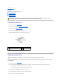
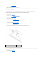
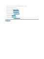
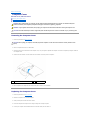
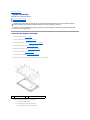
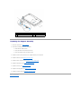
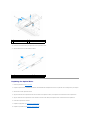
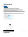
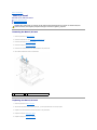
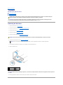
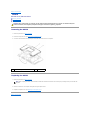
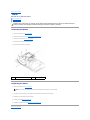
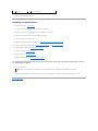
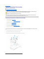
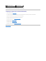
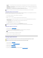
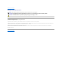
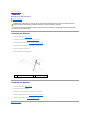
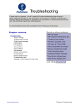
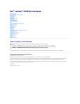
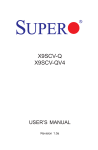
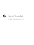
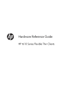
Dell Studio One 19/1909 Service Manual
Technical Overview
Before You Begin
Computer Cover
Shield
Microphone
Stand
Memory Module(s)
Back I/O Panel
Processor Fan and Heat Sink
Processor
Speakers
Drives
Cards
Inverter
System Fan and Heat Sink Assembly
Side I/O Panel
Power Supply Unit
Battery
System Board
Support Assembly
Webcam
System Setup
Notes, Cautions, and Warnings
NOTE: A NOTE indicates important information that helps you make better use of your computer.
CAUTION: A CAUTION indicates either potential damage to hardware or loss of data and tells you how to avoid the problem.
WARNING: A WARNING indicates a potential for property damage, personal injury, or death.
Information in this document is subject to change without notice.
© 2009 Dell Inc. All rights reserved.
Reproduction of these materials in any manner whatsoever without the written permission of Dell Inc. is strictly forbidden.
Trademarks used in this text: Dell and the DELL logo are trademarks of Dell Inc.; Microsoft, Windows, Windows Vista, a n d Windows Vista start button logo are either trademarks or
registered trademarks of Microsoft Corporation in the United States and/or other countries.
Other trademarks and trade names may be used in this document to refer to either the entities claiming the marks and names or their products. Dell Inc. disclaims any
proprietary interest in trademarks and trade names other than its own.
Model MTF
March 2009 Rev. A00
Back to Contents Page
Before You Begin
Dell Studio One 19/1909 Service Manual
Recommended Tools
Turning Off Your Computer
Safety Instructions
This chapter provides procedures for removing and installing the components in your computer. Unless otherwise noted, each procedure assumes that the
following conditions exist:
l
You have performed the steps in Turning Off Your Computer and Safety Instructions.
l
You have read the safety information that shipped with your computer.
l
A component can be replaced or—if purchased separately—installed by performing the removal procedure in reverse order.
Recommended Tools
The procedures in this document may require the following tools:
l
Small Phillips screwdriver
l
Hex nut driver
l
Flash BIOS update program CD
l
Flash BIOS executable update program on the Dell Support website at support.dell.com
Turning Off Your Computer
CAUTION: To avoid losing data, save and close all open files and exit all open programs before you turn off your computer.
1.
Save and close all open files and exit all open programs.
2.
3.
4.
Click the Windows Vista Start button
then click Shut Down.
, in the lower-left corner of the desktop, click the arrow
, in the lower-right corner of the Start menu, and
The computer turns off after the operating system shutdown process is complete.
Ensure that the computer and all attached devices are turned off. If your computer and attached devices did not automatically turn off when you shut
down your operating system, press and hold the power button for about 4 seconds to turn them off.
Safety Instructions
Use the following safety guidelines to help protect your computer from potential damage and to help to ensure your own personal safety.
WARNING: Before working inside your computer, read the safety information that shipped with your computer. For additional safety best
practices information, see the Regulatory Compliance Homepage at www.dell.com/regulatory_compliance.
WARNING: Disconnect all power sources before opening the enclosure to replace, remove, or install accessories. After the installation is
completed, the enclosure must be replaced and all fasteners installed before connecting to the power source.
CAUTION: Only a certified service technician is authorized to remove the computer cover and access any of the components inside the computer.
See the safety instructions for complete information about safety precautions, working inside your computer, and protecting against electrostatic
discharge.
CAUTION: When you disconnect a cable, pull on its connector or on its pull-tab, not on the cable itself. Some cables have connectors with locking
tabs; if you are disconnecting this type of cable, press in on the locking tabs before you disconnect the cable. As you pull connectors apart, keep
them evenly aligned to avoid bending any connector pins. Also, before you connect a cable, ensure that both connectors are correctly oriented
and aligned.
CAUTION: To avoid damaging the computer, perform the following steps before you begin working inside the computer.
1.
Ensure that the work surface is flat and clean to prevent the computer display from being scratched.
2.
Turn off your computer (see Turning Off Your Computer).
CAUTION: To disconnect a network cable, first unplug the cable from your computer and then unplug the cable from the network device.
3.
Disconnect all telephone or network cables from the computer.
4.
Disconnect your computer and all attached devices from their electrical outlets.
5.
Press and hold the power button while the system is unplugged to ground the system board.
CAUTION: Before touching anything inside your computer, ground yourself by touching an unpainted metal surface, such as the metal at the back
of the computer. While you work, periodically touch an unpainted metal surface to dissipate static electricity, which could harm internal
components.
Back to Contents Page
Back to Contents Page
Cards
Dell Studio One 19/1909 Service Manual
Removing the WLAN Card
Replacing the WLAN Card
Removing the RF Module
Replacing the RF Module
WARNING: Before working inside your computer, read the safety information that shipped with your computer. For additional safety best
practices information, see the Regulatory Compliance Homepage at www.dell.com/regulatory_compliance.
Removing the WLAN Card
1.
Follow the instructions in Before You Begin.
2.
Remove the computer cover (see Removing the Computer Cover).
3.
Remove the shield (see Removing the Shield).
4.
Disconnect the antenna cables from the WLAN card.
5.
Release the WLAN card by pressing the clips on either side of the card.
1
antenna cables (2)
2
WLAN card
3
clips (2)
6.
Lift the card away from the system board connector.
Replacing the WLAN Card
CAUTION: The connectors are keyed to ensure correct insertion. Use of excessive force may damage the connectors.
CAUTION: To avoid damage to the WLAN card, ensure that there are no cables under the card. Also, ensure to remove the antenna cables from
under the card.
1.
Follow the instructions in Before You Begin.
2.
Connect the appropriate antenna cables to the WLAN card you are installing. The WLAN card has two triangles on the label (black and white):
l
Connect the black cable to the connector marked with a black triangle.
l
Connect the white cable to the connector marked with a white triangle.
3.
Align the notch on the WLAN card with the tab in the connector slot.
4.
Insert the WLAN card at a 45-degree angle into the system board connector.
5.
Press down on the WLAN card until it clicks in place.
6.
Replace the shield (see Replacing the Shield).
7.
Replace the computer cover (see Replacing the Computer Cover).
Removing the RF Module
WARNING: Before working inside your computer, read the safety information that shipped with your computer. For additional safety best
practices information, see the Regulatory Compliance Homepage at www.dell.com/regulatory_compliance.
1.
Follow the instructions in Before You Begin.
2.
Remove the computer cover (see Removing the Computer Cover).
3.
Remove the shield (see Removing the Shield).
4.
Remove the stand (see Removing the Stand).
5.
Remove the back I/O panel (see Removing the Back I/O Panel).
6.
Remove the processor fan (see Removing the Processor Fan).
7.
Remove the right speaker (see Removing the Right Speaker)
8.
Remove the optical drive (see Removing the Optical Drive).
9.
Remove the screw securing the radio frequency (RF) module, flip the module and disconnect the RF module cable.
1
RF module cable
2
RF module
3
screw
Replacing the RF Module
1.
Follow the instructions in Before You Begin.
2.
To install the RF module, connect the RF module cable.
3.
Flip the RF module and align the screw hole on the RF module with the screw hole on the chassis.
4.
Replace the screw that secures the RF module.
5.
Replace the optical drive (see Replacing the Optical Drive).
6.
Replace the right speaker (see Replacing the Right Speaker).
7.
Replace the processor fan (see Replacing the Processor Fan).
8.
Replace the back I/O panel (see Replacing the Back I/O Panel).
9.
Replace the stand (see Replacing the Stand).
10.
Replace the shield (see Replacing the Shield).
11.
Replace the computer cover (see Replacing the Computer Cover).
Back to Contents Page
Back to Contents Page
Battery
Dell Studio One 19/1909 Service Manual
Removing the Battery
Replacing the Battery
WARNING: Before working inside your computer, read the safety information that shipped with your computer. For additional safety best
practices information, see the Regulatory Compliance Homepage at www.dell.com/regulatory_compliance.
WARNING: A new battery can explode if it is incorrectly installed. Replace the battery only with the same or equivalent type recommended by the
manufacturer. Discard used batteries according to the manufacturer's instructions.
Removing the Battery
1.
Record all the screens in system setup (see System Setup) so that you can restore the correct settings in step 7.
2.
Follow the procedures in Before You Begin.
3.
Remove the computer cover (see Removing the Computer Cover).
4.
Remove the shield (see Removing the Shield).
5.
Disconnect the cables to the connectors HDD_POWER and SATA_1 (see System Board Components).
6.
Locate the battery socket on the system board (see System Board Components).
CAUTION: If you pry the battery out of its socket with a blunt object, be careful not to touch the system board with the object. Ensure that the
object is inserted between the battery and the socket before you attempt to pry out the battery. Otherwise, you may damage the system board by
prying off the socket or by breaking circuit traces on the system board.
1
7.
Carefully press the battery release lever away from the battery and the battery will pop out.
8.
Remove the battery from the system and properly dispose of the battery.
coin-cell battery
2
battery socket
Replacing the Battery
1.
Follow the procedures in Before You Begin.
2.
Insert the new battery into the socket with the side labeled "+" facing up and then snap the battery into place.
3.
Reconnect the cables to the connectors HDD_POWER and SATA_1 (see System Board Components).
4.
Replace the shield (see Replacing the Shield).
5.
Replace the computer cover (see Replacing the Computer Cover).
6.
Connect your computer and devices to electrical outlets, and then turn them on.
7.
Enter system setup (see System Setup) and restore the settings you recorded in step 1.
Back to Contents Page
Back to Contents Page
Computer Cover
Dell Studio One 19/1909 Service Manual
Removing the Computer Cover
Replacing the Computer Cover
WARNING: Before working inside your computer, read the safety information that shipped with your computer. For additional safety best
practices information, see the Regulatory Compliance Homepage at www.dell.com/regulatory_compliance.
WARNING: To guard against electrical shock, always unplug your computer from the electrical outlet before removing the computer cover.
CAUTION: Ensure that sufficient space exists to support the system with the computer cover removed—at least 30 cm (1 ft.) of desk top space.
Removing the Computer Cover
1.
Follow the procedures in Before You Begin.
CAUTION: Before opening your computer, ensure that you place the computer on a soft cloth or clean surface to avoid any scratches on the
display.
2.
3.
4.
1
Place the computer face down on a flat surface.
Starting at the groove at the bottom of the computer cover, use your fingers to separate the computer cover from the computer by lifting the insides of
the computer cover.
Work around the computer cover and gently ease the computer cover away from the computer.
computer cover
5.
2
groove
Lift the computer cover away from the computer and place it aside in a secure location.
Replacing the Computer Cover
1.
Follow the procedures in Before You Begin.
2.
Position the computer cover over the computer.
3.
Gently ease the pins into the holes on the shield.
4.
Press down and push the computer cover along the edges until it snaps into place.
5.
Connect your computer and all attached devices to electrical outlets, and turn them on.
Back to Contents Page
Back to Contents Page
Support Assembly
Dell Studio One 19/1909 Service Manual
Removing the Support Assembly
Replacing the Support Assembly
WARNING: Before working inside your computer, read the safety information that shipped with your computer. For additional safety best
practices information, see the Regulatory Compliance Homepage at www.dell.com/regulatory_compliance.
CAUTION: To avoid electrostatic discharge, ground yourself by using a wrist grounding strap or by periodically touching an unpainted metal
surface (such as the computer stand).
Removing the Support Assembly
1.
Follow the instructions in Before You Begin.
2.
Remove the hard drive (see Removing the Hard Drive).
3.
Remove the power supply unit (see Removing the Power Supply Unit).
4.
Remove the optical drive (see Removing the Optical Drive).
5.
Remove the side I/O panel (see Removing the Side I/O Panel).
6.
Remove the inverter (see Removing the Inverter).
7.
Remove the system board (see Removing the System Board).
8.
Remove the fourteen screws that secure the support assembly to the LCD panel.
1
screws (14)
9.
2
support assembly
Disconnect the following cables from the LCD panel:
l
LVDS cable from LVDS connector
l
touch pad cable from the touch pad connector
l
touch panel cable from the touch panel module
1
touch pad cable
2
LVDS cable
3
touch panel cable
4
LCD panel
Replacing the Support Assembly
1.
Follow the instructions in Before You Begin.
2.
Reconnect the following cables to the LCD panel:
l
LVDS cable from LVDS connector
l
touch pad cable from the touch pad connector
l
touch panel cable from the touch panel module
3.
Replace the fourteen screws that secure the support assembly to the LCD panel.
4.
Replace the hard drive (see Replacing the Hard Drive).
5.
Replace the power supply unit (see Replacing the Power Supply Unit).
6.
Replace the optical drive (see Replacing the Optical Drive).
7.
Replace the inverter (see Replacing the Inverter).
8.
Replace the side I/O panel (see Replacing the Side I/O Panel).
9.
Replace the system board (see Replacing the System Board).
Back to Contents Page
Back to Contents Page
Drives
Dell Studio One 19/1909 Service Manual
Removing the Hard Drive
Replacing the Hard Drive
Removing the Optical Drive
Replacing the Optical Drive
WARNING: Before working inside your computer, read the safety information that shipped with your computer. For additional safety best
practices information, see the Regulatory Compliance Homepage at www.dell.com/regulatory_compliance.
Removing the Hard Drive
1.
Follow the procedures in Before You Begin.
2.
Remove the computer cover (see Removing the Computer Cover).
3.
Remove the shield (see Removing the Shield).
4.
Loosen the two captive screws securing the hard drive carrier to the chassis.
5.
Slide the hard drive towards you and lift it away from the chassis.
6.
Disconnect the hard drive connector from the hard drive.
NOTE: If you are not replacing the hard drive at this time, disconnect the other end of the data cable from the connector (SATA_1) and power
cable from the connector (HDD_POWER) on the system board and set it aside.
7.
8.
Lift the hard drive carrier out of the chassis.
1
hard drive connector
2
hard drive data cable
3
hard drive power cable
4
grooves (2)
5
captive screws (2)
Remove the four screws securing the hard drive to the hard drive carrier.
1
hard drive
2
screws (4)
3
hard drive carrier
Replacing the Hard Drive
1.
2.
Follow the procedures in Before You Begin.
Prepare the new hard drive for installation and check the documentation that accompanied the drive to verify that the drive is configured for your
computer.
3.
Align the screws holes on the hard drive with the screw holes on the hard drive carrier.
4.
Replace the four screws that secure the hard drive to the hard drive carrier.
5.
Reconnect the hard drive connector to the hard drive.
6.
Slide the hard drive carrier into the grooves in the chassis.
7.
Align the screw holes on the hard drive carrier with the screw holes on the chassis.
8.
Tighten the two captive screws that secures the hard drive carrier to the chassis.
9.
Replace the shield (see Replacing the Shield).
10.
Replace the computer cover (see Replacing the Computer Cover).
Removing the Optical Drive
1.
Follow the procedures in Before You Begin.
2.
Remove the computer cover (see Removing the Computer Cover).
3.
Remove the shield (see Removing the Shield).
4.
Remove the stand (see Removing the Stand).
5.
Remove the back I/O panel (see Removing the Back I/O Panel).
6.
Remove the processor fan (see Removing the Processor Fan).
7.
Remove the right speaker (see Removing the Right Speaker).
8.
Disconnect the optical drive connector.
NOTE: If you are not replacing the optical drive at this time, disconnect the other end of the data cable (SATA_2) and power cable (ODD_POWER)
from the system board and set it aside.
9.
Remove the three screws securing the optical drive carrier to the chassis and slide the optical drive carrier out of the computer.
1
optical drive data cable
2
optical drive power cable
3
optical drive connector
4
screws (3)
10.
Remove the four screws securing the optical drive to the optical drive carrier.
11.
Slide the optical drive out of the optical drive carrier.
1
optical drive carrier
2
screws (4)
Replacing the Optical Drive
1.
Follow the procedures in Before You Begin.
2.
Prepare the optical drive for installation and check the documentation that accompanied the drive to verify that the drive is configured for your computer.
3.
Slide the drive into the optical drive carrier.
4.
Align the screw holes on the optical drive with the screw holes on the optical drive carrier, and replace the four screws that secure the optical drive.
5.
Align the screw holes on the optical drive carrier with the screw holes on the chassis, and replace the three screws that secure the optical drive.
6.
Reconnect the optical drive connector.
7.
Replace the right speaker (see Replacing the Right Speaker).
8.
Replace the processor fan (see Replacing the Processor Fan).
9.
Replace the back I/O panel (see Replacing the Back I/O Panel).
10.
Replace the stand (see Replacing the Stand).
11.
Replace the shield (see Replacing the Shield).
12.
Replace the computer cover (see Replacing the Computer Cover).
Back to Contents Page
Back to Contents Page
Processor Fan and Heat Sink
Dell Studio One 19/1909 Service Manual
Removing the Heat Sink
Replacing the Heat Sink
Removing the Processor Fan
Replacing the Processor Fan
WARNING: Before working inside your computer, read the safety information that shipped with your computer. For additional safety best
practices information, see the Regulatory Compliance Homepage at www.dell.com/regulatory_compliance.
WARNING: The heat sink may be very hot during normal operation. Be sure that it has had sufficient time to cool before you touch it.
CAUTION: Do not perform the following steps unless you are familiar with hardware removal and replacement. Performing these steps
incorrectly could damage your system board. For technical service information, see the Setup Guide.
Removing the Heat Sink
CAUTION: To ensure maximum cooling for the processor, do not touch the heat transfer areas on the processor heat sink. The oils in your skin
can reduce the heat transfer capability of the thermal grease.
1.
Follow the procedures in Before You Begin.
2.
Remove the computer cover (see Removing the Computer Cover).
3.
Remove the shield (see Removing the Shield).
4.
Remove the stand (see Removing the Stand).
5.
Remove the back I/O panel (see Removing the Back I/O Panel).
6.
Loosen the four captive screws that secure the heat sink to the system board.
7.
Remove the screw that secures the heat sink to the chassis.
8.
Carefully lift the heat sink away from the computer.
1
heat sink
2
captive screws (4)
3
screw
Replacing the Heat Sink
CAUTION: Incorrect alignment of the processor heat sink can cause damage to the system board and processor.
1.
Follow the procedures in Before You Begin.
NOTE: The original thermal grease can be reused if the original processor and processor heat sink are reinstalled together. If either the processor
or the processor heat sink is replaced, use the thermal grease provided in the kit to ensure that thermal conductivity is achieved.
2.
Clean the thermal grease from the bottom of the heat sink and reapply it.
3.
Align the screws on the processor heat sink with the screw holes on the chassis.
CAUTION: To prevent damage to the processor follow the marked sequence, this ensures equal pressure on the processor at all times.
4.
Use the marked sequence on the processor heat sink to tighten the four captive screws at the lower end of the processor heat sink.
5.
Replace the screw that secures the heat sink to the chassis.
6.
Replace the back I/O panel (see Replacing the Back I/O Panel).
7.
Replace the stand (see Replacing the Stand).
8.
Replace the shield (see Replacing the Shield).
9.
Replace the computer cover (see Replacing the Computer Cover).
Removing the Processor Fan
WARNING: Do not touch the fan when the computer is powered on.
1
1.
Follow the procedures in Before You Begin.
2.
Remove the computer cover (see Removing the Computer Cover).
3.
Remove the shield (see Removing the Shield).
4.
Remove the three screws securing the processor fan.
5.
Disconnect the processor fan cable from the connector (CPU_FAN1) on the system board.
screws (3)
2
processor fan cable
6.
Lift the processor fan away from the computer and place it in a secure location.
Replacing the Processor Fan
1.
Follow the procedures in Before You Begin.
2.
Connect the processor fan cable to the connector (CPU_FAN1) on the system board.
3.
Replace the three screws securing the processor fan.
4.
Replace the shield (see Replacing the Shield).
5.
Replace the computer cover (see Replacing the Computer Cover).
Back to Contents Page
Back to Contents Page
Inverter
Dell Studio One 19/1909 Service Manual
Removing the Inverter
Replacing the Inverter
WARNING: Before working inside your computer, read the safety information that shipped with your computer. For additional safety best
practices information, see the Regulatory Compliance Homepage at www.dell.com/regulatory_compliance.
Removing the Inverter
1.
Follow the procedures in Before You Begin.
2.
Remove the computer cover (see Removing the Computer Cover).
3.
Remove the shield (see Removing the Shield).
4.
Remove the stand (see Removing the Stand).
5.
Remove the back I/O panel (see Removing the Back I/O Panel).
6.
Remove the processor fan and heat sink (see Removing the Heat Sink and Removing the Processor Fan).
7.
Remove the right speaker (see Removing the Right Speaker).
8.
Remove the optical drive (see Removing the Optical Drive).
9.
Remove the two screws that secure the inverter to the chassis.
10.
Disconnect the inverter cable from the inverter.
11.
Disconnect the two cables that connect the inverter to the LCD panel.
12.
Lift the inverter out of the chassis.
1
screws (2)
2
cables to the LCD panel (2)
3
inverter cable
Replacing the Inverter
1.
Follow the procedures in Before You Begin.
2.
To replace the inverter, connect the two cables from the LCD panel to the inverter.
3.
Connect the inverter cable to the system board connector (INVERTER).
4.
Replace the two screws that secure the inverter to the chassis.
5.
Replace the optical drive (see Replacing the Optical Drive).
6.
Replace the right speaker (see Replacing the Right Speaker).
7.
Replace the processor fan and heat sink (see Replacing the Heat Sink and Replacing the Processor Fan).
8.
Replace the back I/O panel (see Replacing the Back I/O Panel).
9.
Replace the stand (see Replacing the Stand).
10.
Replace the shield (see Replacing the Shield).
11.
Replace the computer cover (Computer Cover).
Back to Contents Page
Back to Contents Page
Back I/O Panel
Dell Studio One 19/1909 Service Manual
Removing the Back I/O Panel
Replacing the Back I/O Panel
WARNING: Before working inside your computer, read the safety information that shipped with your computer. For additional safety best
practices information, see the Regulatory Compliance Homepage at www.dell.com/regulatory_compliance.
Removing the Back I/O Panel
1.
Follow the procedures in Before You Begin.
2.
Remove the computer cover (see Removing the Computer Cover).
3.
Remove the shield (see Removing the Shield).
4.
Remove the stand (see Removing the Stand).
5.
Remove the two screws that secure the back I/O panel to the system board.
6.
Lift the back I/O panel away from the system board.
1
screws (2)
2
back I/O panel connector
Replacing the Back I/O Panel
1.
Follow the procedures in Before You Begin.
2.
Slide the back I/O panel into the connector (PCIE_4X_1) on the system board until it is securely in place.
3.
Replace the two screws that secure the back I/O panel to the system board.
4.
Replace the stand (see Replacing the Stand).
5.
Replace the shield (see Replacing the Shield).
6.
Replace the computer cover (see Replacing the Computer Cover).
7.
Connect your computer and all attached devices to electrical outlets, and turn them on.
Back to Contents Page
Back to Contents Page
Memory Module(s)
Dell Studio One 19/1909 Service Manual
Removing Memory Module(s)
Replacing Memory Module(s)
WARNING: Before working inside your computer, read the safety information that shipped with your computer. For additional safety best
practices information, see the Regulatory Compliance Homepage at www.dell.com/regulatory_compliance.
Removing Memory Module(s)
1.
Follow the procedures in Before You Begin.
2.
Remove the computer cover (see Removing the Computer Cover).
3.
Remove the shield (see Removing the Shield).
4.
To remove the memory module, push apart the securing clips on the memory module connector until the module pops up.
1
memory module connector
2
tab
3
securing clips (2)
4
memory module
Replacing Memory Module(s)
CAUTION: If the memory module is not installed properly, the computer may not boot.
1.
Follow the procedures in Before You Begin.
2.
Align the notch of the memory module with the tab on the memory module connector.
3.
Slide the module firmly into the slot at a 45-degree angle, and press the module down until it clicks into place.
If you do not hear the click, remove the module and reinstall it.
4.
Replace the shield (see Replacing the Shield).
5.
Replace the computer cover (see Replacing the Computer Cover).
6.
Connect your computer and all attached devices to electrical outlets, and then turn them on.
7.
When the message appears stating that memory size has changed, press <F1> to continue.
8.
Log on to your computer.
9.
To verify that the memory is installed correctly, click
® Control Panel ® System.
10.
Check the amount of memory (RAM) listed.
Back to Contents Page
Back to Contents Page
Microphone
Dell Studio One 19/1909 Service Manual
Removing the Microphone
Replacing the Microphone
WARNING: Before working inside your computer, read the safety information that shipped with your computer. For additional safety best
practices information, see the Regulatory Compliance Homepage at www.dell.com/regulatory_compliance.
Removing the Microphone
1.
Follow the procedures in Before You Begin.
2.
Remove the computer cover (see Removing the Computer Cover).
3.
Remove the shield (see Removing the Shield).
4.
Remove the two screws that secure the microphone to the support assembly.
5.
Disconnect the cable from the microphone.
6.
Lift the microphone away from the support assembly.
1
microphone
2
screws (2)
3
microphone cable
Replacing the Microphone
1.
Follow the procedures in Before You Begin.
2.
Reconnect the cable to the microphone.
3.
Replace the two screws that secure the microphone to the system assembly.
4.
Replace the shield (see Replacing the Shield).
5.
Replace the computer cover (see Replacing the Computer Cover).
6.
Connect your computer and all attached devices to electrical outlets, and turn them on.
Back to Contents Page
Back to Contents Page
Processor
Dell Studio One 19/1909 Service Manual
Removing the Processor
Replacing the Processor
WARNING: Before working inside your computer, read the safety information that shipped with your computer. For additional safety best
practices information, see the Regulatory Compliance Homepage at www.dell.com/regulatory_compliance.
CAUTION: Do not perform the following steps unless you are familiar with hardware removal and replacement. Performing these steps
incorrectly could damage your system board. For technical service information, see the Setup Guide.
Removing the Processor
1.
Follow the procedures in Before You Begin.
2.
Remove the computer cover (see Removing the Computer Cover).
3.
Remove the shield (see Removing the Shield).
4.
Remove the stand (see Removing the Stand).
5.
Remove the back I/O panel (see Removing the Back I/O Panel).
WARNING: The heat sink may be very hot during normal operation. Be sure that it has had sufficient time to cool before you touch it.
6.
Remove the processor heat sink (see Removing the Heat Sink).
NOTE: Unless a new heat sink is required for the new processor, reuse the original heat sink when you replace the processor.
7.
Press and push the release lever down and out to release it from the tab that secures it.
8.
Open the processor cover.
1 processor cover
2 processor
3 processor socket 4 release lever
CAUTION: When removing or replacing the processor, do not touch any of the pins inside the socket or allow any objects to fall on the pins in the
socket.
9.
Lift up the processor to remove it from the socket, place it aside in a safe and secure place.
Replacing the Processor
1.
Follow the procedures in Before You Begin.
2.
Lift the release lever to the release position so that the socket is ready for the new processor.
CAUTION: Ground yourself by touching an unpainted metal surface or the computer stand.
3.
Unpack the new processor.
1
processor cover
2
processor
3
processor socket
4
center cover latch
5
release lever
6
front alignment notch
7
processor pin-1 indicator
8
rear alignment notch
9
tab
4.
If the release lever on the socket is not fully extended, move it to that position.
CAUTION: Socket pins are delicate. To avoid damage, ensure that the processor is aligned properly with the socket, and do not use excessive
force when you install the processor. Be careful not to touch or bend the pins on the system board.
CAUTION: You must position the processor correctly in the socket to avoid permanent damage to the processor.
5.
Orient the front and rear alignment notches on the processor with the front and rear alignment notches on the socket.
6.
Align the pin-1 corners of the processor and socket.
7.
Place the processor lightly in the socket and ensure that the processor is positioned correctly.
8.
When the processor is fully seated in the socket, close the processor cover.
Ensure that the tab on the processor cover is positioned underneath the center cover latch on the socket.
9.
10.
Pivot the socket release lever back towards the socket, and snap it into place to secure the processor.
Clean the thermal grease from the bottom of the heat sink.
CAUTION: Ensure that you apply new thermal grease. New thermal grease is critical for ensuring adequate thermal bonding, which is a
requirement for optimal processor operation.
11.
Apply the new thermal grease to the top of the processor.
CAUTION: Ensure that the processor heat sink is correctly seated and secure.
12.
Replace the processor heat sink (see Replacing the Heat Sink).
13.
Replace the back I/O panel (see Replacing the Back I/O Panel).
14.
Replace the stand (see Replacing the Stand).
15.
Replace the shield (see Replacing the Shield).
16.
Replace the computer cover (see Replacing the Computer Cover).
17.
Connect your computer and all attached devices to electrical outlets, and then turn them on.
Back to Contents Page
Back to Contents Page
Power Supply Unit
Dell Studio One 19/1909 Service Manual
Removing the Power Supply Unit
Replacing the Power Supply Unit
WARNING: Before working inside your computer, read the safety information that shipped with your computer. For additional safety best
practices information, see the Regulatory Compliance Homepage at www.dell.com/regulatory_compliance.
WARNING: To guard against likelihood of electric shock, laceration by moving fan blades or other unexpected injuries, always unplug your
computer from the electrical outlet before removing the computer cover.
WARNING: Ensure that the part number of the replacement power supply unit matches that of the current power supply unit.
CAUTION: Do not perform the following steps unless you are familiar with hardware removal and replacement. Performing these steps
incorrectly could damage your computer. For technical assistance, see the Setup Guide.
Removing the Power Supply Unit
1.
Follow the procedures in Before You Begin.
2.
Remove the computer cover (see Removing the Computer Cover).
3.
Remove the shield (see Removing the Shield).
4.
Remove the stand (see Removing the Stand).
5.
Disconnect the power plug cable from the power supply unit.
6.
Disconnect the power supply unit cable from the connector (ATX_POWER1) on the system board.
7.
Remove the four screws that secure the power supply unit to the chassis.
1
power supply unit cable
2
screws (4)
3
protective grounding cable screw
4
power plug cable
8.
Place the power supply unit in a secure location.
Replacing the Power Supply Unit
1.
Follow the procedures in Before You Begin.
2.
Replace the four screws that secure the power supply unit to the chassis.
3.
Connect the power supply unit cable to the connector (ATX_POWER1) on the system board.
4.
Connect the power plug cable to the power supply unit.
WARNING: Ensure that the protective grounding cable screw is secure.
5.
Replace the stand (see Replacing the Stand).
6.
Replace the shield (see Replacing the Shield).
7.
Replace the computer cover (see Replacing the Computer Cover).
Back to Contents Page
Back to Contents Page
Shield
Dell Studio One 19/1909 Service Manual
Removing the Shield
Replacing the Shield
WARNING: Before working inside your computer, read the safety information that shipped with your computer. For additional safety best
practices information, see the Regulatory Compliance Homepage at www.dell.com/regulatory_compliance.
Removing the Shield
1.
Follow the procedures in Before You Begin.
2.
Remove the computer cover (see Removing the Computer Cover).
3.
To remove the shield loosen the eight captive screws that secure the shield to the computer.
1
captive screws (8)
2
shield
Replacing the Shield
1.
Follow the procedures in Before You Begin.
NOTE: Before replacing the shield, ensure that all the cables are connected and that no tools or extra parts (including screws) are left inside the
computer.
2.
Position the shield over the computer and tighten the eight captive screws.
3.
Replace the computer cover (see Replacing the Computer Cover).
Back to Contents Page
Back to Contents Page
Side I/O Panel
Dell Studio One 19/1909 Service Manual
Removing the Side I/O Panel
Replacing the Side I/O Panel
WARNING: Before working inside your computer, read the safety information that shipped with your computer. For additional safety best
practices information, see the Regulatory Compliance Homepage at www.dell.com/regulatory_compliance.
Removing the Side I/O Panel
1.
Follow the procedures in Before You Begin.
2.
Remove the computer cover (see Removing the Computer Cover).
3.
Remove the shield (see Removing the Shield).
4.
Remove the stand (see Removing the Stand).
5.
Remove the left speaker (see Removing the Left Speaker).
6.
Remove the hard drive (see Removing the Hard Drive).
7.
Remove the screw that secures the side I/O panel to the chassis.
8.
Lift and pull the side I/O panel from the clamps
NOTE: Make note of the cable routing before you dislodge the cables.
9.
10.
Disconnect the cables from the connectors (F_AUDIO and SIDE_BOARD_1) on the system board.
Slide the side I/O panel away from the clamps and place it in a secure location.
1
screw
2
connector (F_AUDIO)
3
connector (SIDE_BOARD_1)
Replacing the Side I/O Panel
1.
2.
Follow the procedures in Before You Begin.
To replace the side I/O panel, route the cables back into position and connect them to the connectors (F_AUDIO and SIDE_BOARD_1) on the system
board.
3.
Slide the side I/O panel towards the clamps until it is firmly seated.
4.
Replace the screw that secures the side I/O panel to the chassis.
5.
Replace the hard drive (see Replacing the Hard Drive).
6.
Replace the left speaker (see Replacing the Left Speaker).
7.
Replace the stand (see Replacing the Stand).
8.
Replace the shield (see Replacing the Shield).
9.
Replace the computer cover (see Replacing the Computer Cover).
Back to Contents Page
Back to Contents Page
Speakers
Dell Studio One 19/1909 Service Manual
Removing the Right Speaker
Replacing the Right Speaker
Removing the Left Speaker
Replacing the Left Speaker
WARNING: Before working inside your computer, read the safety information that shipped with your computer. For additional safety best
practices information, see the Regulatory Compliance Homepage at www.dell.com/regulatory_compliance.
Removing the Right Speaker
NOTE: To locate the right speaker, see Inside View of Your Studio One.
1.
Follow the procedures in Before You Begin.
2.
Remove the computer cover (see Removing the Computer Cover).
3.
Remove the shield (see Removing the Shield).
4.
Remove the stand (see Removing the Stand).
5.
Remove the processor fan and heat sink (see Removing the Heat Sink and Removing the Processor Fan).
6.
Remove the four screws that secure the speaker to the chassis.
NOTE: Make a note of the cable routing before you dislodge the cable.
7.
Disconnect the right speaker cable from the connector (SPEAKER_2) on the system board.
1
screws (4)
8.
2
speaker cable
Lift the speaker away from the chassis.
Replacing the Right Speaker
1.
Follow the procedures in Before You Begin.
2.
To replace the speaker, route the speaker cables back into position.
3.
Connect the right speaker cable to the connector (SPEAKER_2) on the system board.
4.
Place the speaker in position and replace the four screws that secure the speaker to the chassis.
5.
Replace the processor fan and heat sink (see Replacing the Heat Sink and Replacing the Processor Fan).
6.
Replace the stand (see Replacing the Stand).
7.
Replace the shield (see Replacing the Shield).
8.
Replace the computer cover (see Replacing the Computer Cover).
9.
Connect your computer and all attached devices to electrical outlets, and turn them on.
Removing the Left Speaker
NOTE: To locate the left speaker, see Inside View of Your Studio One.
1.
Follow the procedures in Before You Begin.
2.
Remove the computer cover (see Removing the Computer Cover).
3.
Remove the shield (see Removing the Shield).
4.
Remove the four screws that secure the speaker to the chassis.
NOTE: Make a note of the cable routing before you dislodge the cable.
5.
Disconnect the left speaker cable from the connector (SPEAKER_1) on the system board.
1
screws (4)
6.
2
speaker cable
Lift the speaker away from the system board.
Replacing the Left Speaker
1.
Follow the procedures in Before You Begin.
2.
To replace the speaker, route the cables back into position.
3.
Reconnect the left speaker cable to the connector (SPEAKER_1) on the system board.
4.
Replace the four screws that secure the speaker to the chassis.
5.
Replace the shield (see Replacing the Shield).
6.
Replace the computer cover (see Replacing the Computer Cover).
Back to Contents Page
Back to Contents Page
Stand
Dell Studio One 19/1909 Service Manual
Removing the Stand
Replacing the Stand
WARNING: Before working inside your computer, read the safety information that shipped with your computer. For additional safety best
practices information, see the Regulatory Compliance Homepage at www.dell.com/regulatory_compliance.
Removing the Stand
1.
Follow the procedures in Before You Begin.
2.
Remove the computer cover (see Removing the Computer Cover).
3.
Remove the shield (see Removing the Shield).
4.
Remove the four screws securing the stand.
5.
Lift the stand away from the computer.
1
screws (4)
2
stand
Replacing the Stand
1.
Follow the procedures in Before You Begin.
NOTE: Ensure that you remove the labels from the existing stand and fix them on the new stand.
2.
To replace the stand, align the screw holes on the stand with the screw holes on the chassis.
3.
Replace the four screws that secure the stand.
4.
Replace the shield (Replacing the Shield).
5.
Replace the computer cover (see Replacing the Computer Cover).
Back to Contents Page
Back to Contents Page
System Board
Dell Studio One 19/1909 Service Manual
Removing the System Board
Replacing the System Board
WARNING: Before working inside your computer, read the safety information that shipped with your computer. For additional safety best
practices information, see the Regulatory Compliance Homepage at ww.dell.com/regulatory_compliance.
CAUTION: To avoid electrostatic discharge, ground yourself by using a wrist grounding strap or by periodically touching an unpainted metal
surface (such as the stand).
The system board's BIOS chip contains the Service Tag, which is also visible on a barcode label on the computer. The replacement kit for the system board
includes a CD that provides a utility for transferring the Service Tag to the replacement system board.
CAUTION: Handle components and cards by their edges, and avoid touching pins and contacts.
Removing the System Board
1.
Follow the instructions in Before You Begin.
2.
Remove the computer cover (see Removing the Computer Cover).
3.
Remove the shield (see Removing the Shield).
4.
Remove the stand (see Removing the Stand).
5.
Remove the back I/O panel (see Removing the Back I/O Panel).
6.
Remove the processor fan and heat sink (see Removing the Processor Fan and Removing the Heat Sink).
7.
Remove the system fan and heat sink assembly (see Removing the System Fan and Heat Sink Assembly).
NOTE: Make note of the cable routing before disconnecting the cables from the system board.
8.
Disconnect all the cables connected the system board.
9.
Remove the five screws that secure the system board to the chassis.
10.
Remove the five M2.5 x 5-mm screws that secure the system board to the chassis.
1
screws (5)
11.
2
M2.5 x 5-mm screws (5)
Lift the system board out of the chassis.
Replacing the System Board
1.
Follow the instructions in Before You Begin.
2.
To replace the system board place the system board back in the chassis.
3.
Replace the five M2.5 x 5-mm screws that secure the system board to the chassis.
4.
Replace the five screws that secure the system board to the chassis.
5.
Reconnect the cables to the system board.
6.
Replace the system fan and heat sink assembly (see Replacing the System Fan and Heat Sink Assembly).
7.
Replace the processor fan and heat sink (see Replacing the Processor Fan and Replacing the Heat Sink).
8.
Replace the back I/O panel (see Replacing the Back I/O Panel).
9.
Replace the stand (see Replacing the Stand).
10.
Replace the shield (see Replacing the Shield).
11.
Replace the computer cover (see Replacing the Computer Cover).
CAUTION: Before turning on the computer, replace all screws and ensure that no stray screws remain inside the computer. Failure to do so may
result in damage to the computer.
12.
Turn on the computer.
NOTE: After you have replaced the system board, enter the computer Service Tag in the BIOS of the replacement system board.
13.
Insert the CD that accompanied the replacement system board into the appropriate drive. Follow the instructions that appear on the screen.
Back to Contents Page
Back to Contents Page
System Fan and Heat Sink Assembly
Dell Studio One 19/1909 Service Manual
Removing the System Fan and Heat Sink Assembly
Replacing the System Fan and Heat Sink Assembly
WARNING: Before working inside your computer, read the safety information that shipped with your computer. For additional safety best
practices information, see the Regulatory Compliance Homepage at www.dell.com/regulatory_compliance.
WARNING: Do not touch the fan when the computer is powered on.
CAUTION: Do not perform the following steps unless you are familiar with hardware removal and replacement. Performing these steps
incorrectly could damage your system board. For technical service information, see the Setup Guide.
Removing the System Fan and Heat Sink Assembly
1.
Follow the procedures in Before You Begin.
2.
Remove the computer cover (see Removing the Computer Cover).
3.
Remove the shield (see Removing the Shield).
4.
Remove the stand (see Replacing the Stand).
5.
Remove the back I/O panel (see Removing the Back I/O Panel).
6.
Remove the three screws securing the system fan to the system board.
CAUTION: The heat sink assembly may be very hot during normal operation. Be sure that it has had sufficient time to cool before you touch it.
7.
Loosen the two captive screws securing the heat sink to the system board.
8.
Slide and lift the system fan away from the frame of the computer.
9.
Disconnect the system fan cable from the connector (SYS_FAN1) on the system board.
1
heat sink captive screws (2)
2
system fan screws (3)
3
system fan cable
10.
Lift the assembly away from the system board and place it in a secure location.
Replacing the System Fan and Heat Sink Assembly
1.
Follow the procedures in Before You Begin.
2.
To replace the system fan and heat sink assembly, connect the system fan cable to the connector (SYS_FAN1) on the system board.
3.
Tighten the two captive screws securing the heat sink to the system board.
4.
Replace the three screws securing the system fan to the system board.
5.
Replace the back I/O panel (see Replacing the Back I/O Panel).
6.
Replace the stand (see Replacing the Stand).
7.
Replace the shield (see Replacing the Shield).
8.
Replace the computer cover (see Replacing the Computer Cover).
Back to Contents Page
Back to Contents Page
System Setup
Dell Studio One 19/1909 Service Manual
Overview
Clearing Forgotten Passwords
Clearing CMOS Settings
Flashing the BIOS
Overview
Use system setup to:
l
Change the system configuration information after you add, change, or remove any hardware in your computer
l
Set or change a user-selectable option such as the user password
l
Read the current amount of memory or set the type of hard drive installed
CAUTION: Unless you are an expert computer user, do not change the settings for this program. Certain changes can make your computer work
incorrectly.
NOTE: Before you change system setup, it is recommended that you write down the system setup screen information for future reference.
Entering System Setup
1.
Turn on (or restart) your computer.
2.
When the blue DELL™ logo is displayed, watch for the F2 prompt to appear and then press <F2> immediately. NOTE: The F2 prompt indicates that the keyboard has initialized. This prompt can appear very quickly, so you must watch for it to display, and
then press <F2>. If you press <F2> before you are prompted, this keystroke will be lost. If you wait too long and the operating system logo
appears, continue to wait until you see the Microsoft® Windows® desktop. Then, shut down your computer (see Turning Off Your Computer) and
try again.
System Setup Screens
The system setup screen displays current or changeable configuration information for your computer. Information on the screen is divided into three areas: the
options list, active options field, and key functions.
Options List — This field appears on the left side of the system setup
window. The field is a scrollable list containing features that define the
configuration of your computer, including installed hardware, power
conservation, and security features.
Options Field — This field appears on the right side of the system setup
window and contains information about each option listed in the Options List.
In this field you can view information about your computer and make changes
to your current settings.
Scroll up and down the list with the up- and down-arrow keys. As an option
Press the up-arrow and down-arrow keys to highlight an option. Press
is highlighted, the Options Field displays more information about that option <Enter> to make that selection active and return to the Options List.
and the option's current and available settings.
NOTE: Not all settings listed in the Options Field are changeable.
Key Functions — This field appears below the Options Field and lists keys and their functions within the active system setup field.
System Setup Options
NOTE: Depending on your computer and installed devices, the items listed in this section may appear, or may not appear exactly as listed.
System Info
Bios Info
Displays the BIOS version number.
System
Displays the system name.
Service Tag
Displays the service tag of the computer.
Processor Type
Displays processor information
CPU Speed
Displays the processor speed.
Processor L1 Cache
Displays the processor L1 cache size.
Processor L2 Cache
Displays the processor L2 cache size.
Memory Installed
Indicates the amount of installed memory in MB.
Memory Available
Indicates the amount of memory available in MB.
Memory Speed
Indicates the memory speed in MHz.
Standard CMOS Features
System Time
Displays current time in hh:mm:ss format.
System Date
Displays the current date in mm:dd:yy format.
AHCI Port0
Auto detects IDE devices in port 0.
AHCI Port1
Auto detects IDE devices in port 1.
Advanced BIOS Features
CPU Feature
Describes type of processor.
USB Device Setting
Enable or disable the USB controller /Set the operational USB speed.
Advanced Chipset Features
Onboard Audio Controller
Allows you to enable or disable the audio controller.
SATA Mode select
Allows you to switch between AHCI and IDE.
Onboard LAN Controller
Allows you to enable or disable onboard Broadcom network controller.
Onboard LAN Boot ROM
Allows you to enable or disable ROM for Broadcom PCI E Network Controller.
Boot Device Configuration
Boot Settings Configuration
Enable or disable fast boot and Numlock key.
Hard Disk Boot Priority
Sets the hard drive boot priority. The items displayed are dynamically updated according to the hard drives detected.
1st Boot Device
Specifies the boot sequence from the available devices.
Removable; CD/DVD; Hard Drive; Disabled (Removable by default).
2nd Boot Device
Specifies the boot sequence from the available devices.
Removable; CD/DVD; Hard Drive; Disabled (CD/DVD by default).
3rd Boot Device
Specifies the boot sequence from the available devices.
Removable; CD/DVD; Hard Drive; Disabled (CD/DVD by default).
Boot Other Device
Allows you to boot through any other device.
Power Management Features
ACPI Suspend Type
Specifies the suspend type. The default is S3.
C1E Support
This option allows you to enable or disable the "Enhanced Halt State".
Remote Wake Up
This option turns on the computer when a user tries to access the computer through the LAN. The default is Enabled.
AC Recovery
Auto Power On
Enables you to set an alarm to turn on the computer automatically. The default is Disabled.
BIOS Security Features
Supervisor Password
Status of supervisor password installed.
User Password
Status of user password installed.
Set Supervisor Password
Allows to set the desired supervisor password.
Exit
Exit Options
Provides options to Load Optimal Default, Save and Exit Setup, and Exit Without Saving.
Boot Sequence
This feature allows you to change the boot sequence for devices.
Boot Options
l
Hard Drive — The computer attempts to boot from the primary hard drive. If no operating system is on the drive, the computer generates an error
message.
l
CD/DVD Drive — The computer attempts to boot from the CD/DVD drive. If no CD/DVD is in the drive, or if the CD/DVD has no operating system, the
computer generates an error message.
l
USB Flash Device — Insert the memory device into a USB port and restart the computer. When F12 = Boot Menu appears in the upper-right corner of
the screen, press <F12>. The BIOS detects the device and adds the USB flash option to the boot menu.
NOTE: To boot to a USB device, the device must be bootable. To ensure that your device is bootable, check the device documentation.
Changing Boot Sequence for the Current Boot
You can use this feature to change the current boot sequence, for example, to boot from the CD/DVD drive to run the Dell Diagnostics on the Drivers and
Utilities media. On completion of diagnostic tests, the previous boot sequence is restored.
1.
If you are booting to a USB device, connect the USB device to a USB connector.
2.
Turn on (or restart) your computer.
3.
When F2 = Setup, F12 = Boot Menu appears in the upper-right corner of the screen, press <F12>.
If you wait too long and the operating system logo appears, continue to wait until you see the Microsoft Windows desktop. Then shut down your
computer and try again.
The Boot Device Menu appears, listing all available boot devices. Each device has a number next to it.
4.
On the Boot Device Menu choose the device you want to boot from.
For example, if you are booting to a USB memory key, highlight USB Flash Device and press <Enter>.
NOTE: To boot to a USB device, the device must be bootable. To ensure your device is bootable, check the device documentation.
Changing Boot Sequence for Future Boots
1.
Enter system setup (see Entering System Setup).
2.
Use the arrow keys to highlight the Boot Device Configuration menu option and press <Enter> to access the menu.
NOTE: Write down your current boot sequence in case you want to restore it.
3.
Press the up- and down-arrow keys to move through the list of devices.
4.
Press plus (+) or minus (–) to change the boot priority of the device.
Clearing Forgotten Passwords
WARNING: Before you begin any of the procedures in this section, follow the safety instructions that shipped with your computer.
WARNING: The computer must be disconnected from the electrical outlet to clear the password setting.
1.
Follow the procedures in Before You Begin.
2.
Remove the computer cover (see Removing the Computer Cover).
3.
Remove the shield (seeRemoving the Shield).
4.
Remove the stand (see Removing the Stand).
5.
Locate the 3-pin password connector (CLR_PSWD) on the system board (see System Board Components).
6.
Remove the 2-pin jumper plug from pins 2 and 3 and fix it on pins 1 and 2.
7.
Wait for approximately five seconds to clear the password setting.
8.
Remove the 2-pin jumper plug from pins 1 and 2 and replace it on pins 2 and 3.
9.
Replace the stand (see Replacing the Stand).
10.
Replace the shield (see Replacing the Shield).
11.
Replace the computer cover (see Replacing the Computer Cover).
12.
Connect your computer and devices to electrical outlets, and turn them on.
Clearing CMOS Settings
WARNING: Before you begin any of the procedures in this section, follow the safety instructions that shipped with your computer.
WARNING: The computer must be disconnected from the electrical outlet to clear the CMOS setting.
1.
Follow the procedures in Before You Begin.
2.
Remove the computer cover (see Removing the Computer Cover).
3.
Removing the shield (see Removing the Shield).
4.
Remove the stand (see Removing the Stand).
5.
Remove the back I/O panel (see Removing the Back I/O Panel).
6.
Locate the 3-pin CMOS connector (CLR_CMOS) on the system board (see System Board Components).
7.
Remove the 2-pin jumper plug from pins 2 and 3 and fix it on pins 1 and 2.
8.
Wait for approximately five seconds to clear the CMOS setting.
9.
Remove the 2-pin jumper plug from pins 1 and 2 and replace it on pins 2 and 3.
10.
Replace the back I/O panel (see Replacing the Back I/O Panel).
11.
Replace the shield (see Replacing the Shield).
12.
Replace the stand (see Replacing the Stand).
13.
Replace the computer cover (see Replacing the Computer Cover).
14.
Connect your computer and devices to electrical outlets, and turn them on.
Flashing the BIOS
Flashing the BIOS From the Hard Drive
1.
Turn on the computer.
2.
Locate the BIOS update file for your computer at the Dell Support website at support.dell.com.
NOTE: For non U.S. regions, choose your country/region from the drop-down list at the bottom of the Dell support website and then locate the
BIOS update file for your computer.
3.
Click Download Now to download the file.
4.
If the Export Compliance Disclaimer window appears, click Yes, I Accept this Agreement.
The File Download window appears.
5.
Click Save this program to disk, and then click OK.
The Save In window appears.
6.
Click the down arrow to view the Save In menu, select Desktop, and then click Save.
The file downloads to your desktop.
7.
Click Close when the Download Complete window appears.
The file icon appears on your desktop and is titled the same as the download BIOS update file.
8.
Double-click the file icon on the desktop and follow the instructions on the screen.
Flashing the BIOS From a CD
1.
Turn on the computer
NOTE: If you use a BIOS upgrade CD to flash the BIOS, set up the computer to boot from a CD before inserting the CD.
2.
Insert the BIOS upgrade CD, and restart the computer.
Follow the instructions that appear on the screen. The computer continues to boot and updates the new BIOS. When the flash update is complete, the
computer will automatically reboot.
3.
Press <F2> during POST to enter the system setup program.
4.
Click Load Defaults and click OK in pop-up window to reset the computer defaults.
5.
Remove the BIOS upgrade CD from the drive.
6.
Press <Esc> and click Yes in the pop-up window to save configuration changes.
7.
The BIOS upgrade finishes and the computer restarts automatically.
Back to Contents Page
Back to Contents Page
Technical Overview
Dell Studio One 19/1909 Service Manual
Inside View of Your Studio One
System Board Components
WARNING: Before working inside your computer, read the safety information that shipped with your computer. For additional safety best
practices information, see the Regulatory Compliance Homepage at www.dell.com/regulatory_compliance.
Inside View of Your Studio One
1
processor fan
2
back I/O panel
3
left speaker
4
side I/O panel
5
hard drive
6
stand
7
optical drive
8
right speaker
System Board Components
1
password jumper (CLR_PSWD)
2
LCD connector (LVDS)
3
back I/O panel, PCI Express x4
connector (PCIE_4X_1)
4
power supply unit connector
(ATI_POWER1)
5
inverter connector (INVERTER)
6
touch pad connector
(TOUCH_PAD)
7
optical drive connector
(ODD_POWER)
8
serial ATA drive connector
(SATA_2)
9
RF connector (RF_1)
10 CMOS jumper (CLR_CMOS)
11 processor
12 processor fan connector
(CPU_FAN1)
13 right speaker connector
(SPEAKER_2)
14 memory module connector
(SODIMM1)
15 memory module connector
(SODIMM2)
16 webcam connector (WEBCAM)
17 digital microphone connector
(DIGITAL_MIC)
18 left speaker connector
(SPEAKER_1)
19 WLAN connector (WLAN)
20 side I/O panel connector
(SIDE_BOARD1)
21 serial ATA drive connector (SATA_1)
22 hard drive power connector
(HDD_POWER)
23 battery socket (BAT1)
24 front audio connector
(F_AUDIO)
25 system fan connector (SYS_FAN1)
26 thermal resistor connector
(TEM)
27 touch panel connector
(TOUCH_PANEL)
Back to Contents Page
Back to Contents Page
Dell Studio One 19/1909 Service Manual
NOTE: A NOTE indicates important information that helps you make better use of your computer.
CAUTION: A CAUTION indicates either potential damage to hardware or loss of data and tells you how to avoid the problem.
WARNING: A WARNING indicates a potential for property damage, personal injury, or death.
Information in this document is subject to change without notice.
© 2009 Dell Inc. All rights reserved.
Reproduction of these materials in any manner whatsoever without the written permission of Dell Inc. is strictly forbidden.
Trademarks used in this text: Dell and the DELL logo are trademarks of Dell Inc.; Microsoft, Windows, Windows Vista, a n d Windows Vista start button logo are either trademarks or
registered trademarks of Microsoft Corporation in the United States and/or other countries.
Other trademarks and trade names may be used in this document to refer to either the entities claiming the marks and names or their products. Dell Inc. disclaims any
proprietary interest in trademarks and trade names other than its own.
March 2009 Rev. A00
Back to Contents Page
Back to Contents Page
Webcam
Dell Studio One 19/1909 Service Manual
Removing the Webcam
Replacing the Webcam
WARNING: Before working inside your computer, read the safety information that shipped with your computer. For additional safety best
practices information, see the Regulatory Compliance Homepage at www.dell.com/regulatory_compliance.
CAUTION: To avoid electrostatic discharge, ground yourself by using a wrist grounding strap or by periodically touching an unpainted metal
surface (such as the computer stand).
Removing the Webcam
1.
Follow the instructions in Before You Begin.
2.
Remove the system board (see Removing the System Board).
3.
Remove the support assembly (see Removing the Support Assembly).
4.
Remove the two screws that secure the webcam to the LCD panel.
5.
Disconnect the cable to the webcam.
6.
Lift the webcam away from the LCD panel.
1
webcam cable
2
screws (2)
Replacing the Webcam
1.
Follow the instructions in Before You Begin.
2.
Reconnect the cable to the webcam.
3.
Replace the two screws that secure the webcam to the LCD panel.
4.
Replace the support assembly (see Replacing the Support Assembly).
5.
Replace the system board (see Replacing the System Board).
Back to Contents Page