1
TEST PORT CONNECTOR AND PORT MODULE REMOVAL AND REPLACEMENT
7-6
TEST PORT
CONNECTOR AND
PORT MODULE
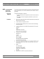
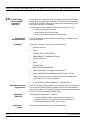
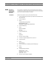
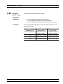
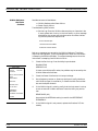
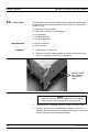
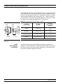
Tools Required:
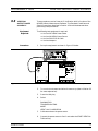
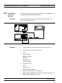
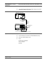
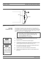
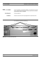
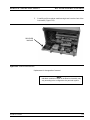
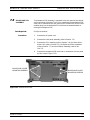
The following procedure describes the proper steps to remove and install
the Test Port Connector and Port Module.
q
q
q
q
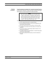
Removal
Procedure:
Installation
Procedure:
7-20
Anritsu 01-202 universal adapter wrench
5/8” open end wrench
5/8” open end torque wrench, 120 in-lb
5/16” open end torque wrench, 8 in-lb
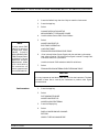
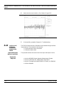
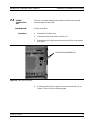
1.
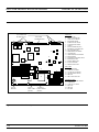
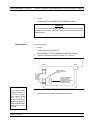
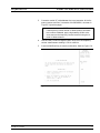
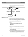
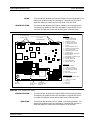
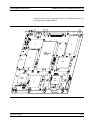
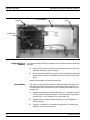
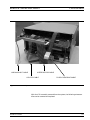
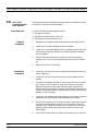
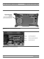
Remove the Port Module mounting screws from the receiver PCB.
2.
Loosen the RF cables connected to the Port Module.
3.
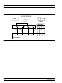
Loosen the K connection between the Port Module and the Test Port
Connector and carefully slide the Port Module backward. Remove
the Port Module.
4.
Use the 5/8” open end wrench to loosen the Test Port connector
mounting nut. This nut is on the back side of the Test Port connector.
5.
Remove the Test Port Connector.
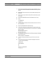
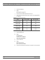
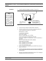
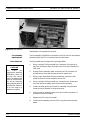
1.
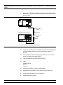
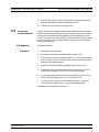
Install the Test Port Connector through the D-shape hole on the Receiver metal tray.
2.
Install the Test Port connector mounting nut and tighten the nut
slightly.
3.
Place the Port Module with the “P” port facing the Test Port connector. Connect the Port Module “P” port to the Test Port connector.
Make the connection finger tight and then loosen a quarter turn.
While making the connection, keep the Port Module flat against the
receiver PCB and be careful not to damage the center pin of the Port
Module “P” port connector.
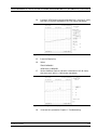
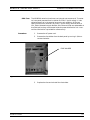
4.
Install the Port Module mounting screws only far enough to hold the
module flat but still allowing some movement front to back.
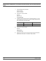
5.
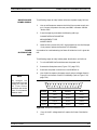
Use the 5/8” wrench on the Test Port connector mounting nut, while
using the universal adapter wrench in front to hold the Test Port
connector still. Tighten the mounting nut as tight as you can while
holding the Port Module flat against the receiver PCB with your
other fingers.
6.
Use the 5/8” torque wrench to tighten the mounting nut to 120 in-lb.
MS462XX MM