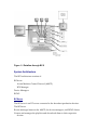
1
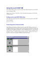
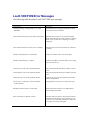
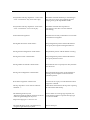
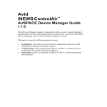
Avstar Systems, LLC™
Louth VDCP Device Manager
Version 1.0.2 Device Operation Guide
This addendum provides information on how to install and use the Avstar™
Newsroom Computer System (NRCS) Broadcast Control System™ (BCS) Device
Manager (DM) for the Louth Video Disk Control Protocol (VDCP).
Preface
Who Should Use This Manual
This manual is written for journalists, producers, directors, writers, and various
technical personnel using Avstar BCS in a broadcast newsroom.
About This Manual
This manual contains the following information:
Chapter 1, Installing the BCS Louth VDCP Device Manager
Chapter 2, Configuring the BCS Louth VDCP Device Manager
Chapter 3, Using the BCS Louth VDCP Device Manager
Appendix A, Louth VDCP DM Error Messages
Symbols and Conventions
This manual uses the following special symbols and conventions.
Structure of Text
Numbered lists, when the order of the primary items is important.
Alphabetical lists, when the order of secondary items is important.
Bulleted lists, when the order of primary items is unimportant.
Indented dashed lists, when the order of secondary items is unimportant.
Look here in the margin for tips and environment-specific information.
In the margin you will find tips that help you perform tasks more easily and
efficiently. You will also find information specific to a particular operating
environment.
A note provides important related information, reminders, recommendations, and strong
suggestions.
A caution means that a specific action you take could harm your computer or
cause you to lose data.
Keyboard Conventions
Control-x means to press and hold down the Control key and then press another
key.
“Type” in a command procedure means to type the command on the command
line and then press the Enter key.
Console Conventions
Commands that you enter at the console, console screen displays, and console
prompts are presented in a typewriter-style typeface called courier:
Commands that you need to type are in bold courier. If you are instructed to
type a console command, for instance, the instructions look something like
this:
Type so at the login: prompt.
Output to the console screen is in plain courier:
WAVSTAR_A: list s
T11
miller
A
T23
stevens A
T82
allen
B
Some console displays shown in this manual are quite long. To make them more
understandable, the lengthy console displays have been shortened to emphasize
only the most important information. An ellipsis (...) represents portions of the
console display not shown in the text.
The console can display each computer’s prompt, based on the system ID and the
computer’s name. Examples in this addendum may use a fictional station and
system ID of WAVSTAR. For example, the following is the console prompt for
computer A on the WAVSTAR system:
WAVSTAR_A:
Support
If you are having trouble performing a system operation, you should:
Repeat the procedure, carefully following the instructions provided for the task
in this guide.
Check the documentation that came with your hardware for maintenance or
hardware-related issues.
Check the Services & Support section of the Avstar web site at
http://www.avstarnews.com for the latest FAQs, Tips & Techniques,
Broadcast Update, and other Avstar online offerings.
Check the Avstar Bulletin Board for information on product and user
conferences. If you do not find the solution to your problem, you can
exchange information with other Avstar customers and Technical Support
representatives.
http://support.avstarnews.com/~avstar
Send E-mail to support
[email protected]
Maintenance Agreement contract customers can contact Avstar
Technical Support at:
1-800-547-8949 in the USA
44-1753-655999 in Europe
65-476-7666 in Asia/Pacific
Avstar Broadcast Control System Documentation
Avstar (formerly AvidNews) Broadcast Control Workstation User’s Guide describes
the user-level software functions for BCS.
Avstar (formerly AvidNews) Broadcast Control Workstation online help gives you
quick-reference information about user-level software functions.
Avstar (formerly AvidNews) Broadcast Control System Installation Guide provides
information on installing and setting up the BCS.
Avstar (formerly AvidNews) Broadcast Control System Release Notes provides
installation, administration, and user-level information that may not have
been available at the time the other documentation was printed.
MCS Release Notes describe administration and user-level information on how to
use the NetStation Machine Control System with the Avstar NRCS.
Documentation Comments
Avstar Systems, LLC continuously seeks to improve its customer documentation.
We value your comments about this manual or other Avstar-supplied
documentation.
Send your documentation comments by e-mail to Avstar Systems at:
[email protected]
Include the title of the document, its part number, revision, and the specific
section that you’re commenting on in all correspondence.
Installing the Louth VDCP
This chapter contains:
An overview of the Avstar Broadcast Control System (BCS)
An overview of the Device Manager (DM) installation process
An Overview of BCS
Avstar BCS
Avstar BCS is a machine control system for on-air operations. BCS can be
integrated into the Avstar Newsroom Computer System (NRCS), or into another
newsroom computer system. It can also operate in a standalone environment if
the NRCS connection is lost.
BCS consists of a server, one or more Broadcast Control Workstations (BCWS),
and several device managers. BCS:
Directly controls production devices
Receives information from the Avstar Workstation as control events are entered
into scripts
Handles several shows at the same time, enabling shows to be produced back-toback
Windows-based GUI clients allow technical directors to control events on the
Broadcast Control Server.
Avstar NRCS
The Avstar NRCS product set is constructed on a modular, open architecture,
enabling its components to work efficiently not only with other Avstar products,
but also with third-party hardware and software. Avstar NRCS operates on
industry-standard technologies, including Windows® 95 and Windows NT,
Intel®-based PCs, Intel and Silicon Graphics® (SGI) servers, and TCP/IP Internet
networking protocols.
Avstar Systems is publishing open Applications Programming Interfaces (APIs)
for the Broadcast Control System that will enable integration with third-party
software and hardware.
Overview of Broadcast Control
After the news staff has scripted stories and entered production cues in the
scripts, the producer can download rundowns to BCS using the monitor server in
Avstar NRCS.
From the BCWS, the technical director can access the playlists for downloaded
rundowns and control associated production devices to play production cues
requested.
Figure 1-1 depicts how data flows from Avstar NRCS, through the Avstar
Machine Control Protocol (AMCP), to the Broadcast Control Server (BCServer),
and then to the devices and BCWS.
Figure 1-1 Dataflow through BCS
System Architecture
The BCS architecture consists of:
BCServer
Avstar Machine Control Protocol (AMCP)
BCS Manager
Device Managers
BCWS
BCServer
The BCServer is an NT server connected to the broadcast production devices.
The BCServer:
Routes messages between the AMCP, the device managers, and BCWS clients
Creates and manages the playlists and downloads them to their respective
devices
Tracks which clients have playlists and devices reserved
AMCP
AMCP is the interface between NRCS and BCServer. It translates the data
coming in from Avstar Newsroom Computer System, or other newsroom
computer systems, into data that the BCS can manage.
BCS Manager
The BCS Manager:
Starts the BCS programs
Manages the programs that run on BCServer: AMCP and device managers
Device Managers
The BCWS lets the technical director control the following machines used for
broadcast production:
Character generators
Still stores
Video playback devices (such as Avid AirPlay)
BCWS
The BCWS is an application that runs on Windows NT. From the BCWS, the
technical director can view playlists and device and event status, and control the
broadcast production devices. The BCWS can run on the same machine as the
BCServer, or on a separate machine.
Overview of the Setup
To set up BCS:
Perform tasks for initial setup
Add new users to the system
Initial Setup
Setting up the BCS involves doing tasks in three places:
Avstar NRCS Server
BCServer
BCWS
You may need to consult the AvidNews System Operations Manual for specific
information on the Avstar server or various system operations related to the
news server.
Setup Tasks on the Avstar NRCS Server
In /etc/hosts file, add the IP address/ethernet address for BCServer(s),
devices, and BCWS(s).
If you’re upgrading from MCS, you may have to remove device information for
machines (CGs, and so on) from the /site/config file. See your installation
guide for information on what changes to make if upgrading.
Create a monitor server for each show.
In the System Map story, add an entry for each show.
In the System Map story, also add a device list.
Create composite and event list queues.
These tasks are described in subsequent chapters of this book.
Assign a form to the composite and event list queues. This is for viewing these
lists on the news system.
Set up the default BCWS form.
In the system resource stories, define styles for device commands.
These tasks are described in subsequent chapters of this book.
Setup Tasks on the Broadcast Control Server
In BCServer autostart.ini file, add an entry for each device. This file is in:
Program files/Avid/Broadcast Control System.
Add device manager profiles for all production devices.
These tasks are described in subsequent chapters of this
book.
Adding New Shows or Devices
After the initial setup, you may need to add shows or new devices to your
system. To do this, you will have to do only some of the setup tasks listed above.
Louth VDCP DM
Once BCS has been installed, you must set up the Avstar NRCS server before you
can use the system. There are setup tasks that must be performed on the Avstar
server at the console, and tasks that must be performed on the Avstar Newsroom
Computer System (NRCS) Workstation (the client).
For more information about any Avstar/AvidNews task, see the AvidNews
Newsroom Computer System Operations Manual and the AvidNews Newsroom
Computer System User’s Guide. For further information on installing and operating
BCS, refer to the AvidNews BCS Installation Guide, AvidNews BCS Operations
Manual, and the AvidNews BCS User Guide.
New Features of BCS Components
If channels are being assigned by BCWS and a new playlist is downloaded to the
DM, it will report a status of Available for each event available on a
channel.
If an event is not available on a channel, the status will be Unavailable. When
the playlist is reserved, BCWS will assign channels; at that point, the DM will
report the status of each event on its assigned channel.
However, if channels are assigned by NRCS or by the DM, the event is assigned
a channel at download time, and its status is reported relative to that channel.
BCWS New Channel Change Features:
The Broadcast Æ Channel Override menu entry has been renamed Cycle
Channels.
There is a new Broadcast submenu named Change Channel. It contains 10
channels with corresponding accelerator keys 1 through 0. The effect is to
change the channel of a selected event directly to a desired channel, rather
than cycling through channels to reach the desired channels.
There is a new option on the Channel Policy tab of the Broadcast Æ Options
dialog. It is a check box labeled “Enable Cycle Channels key;” by default it is
unchecked. This option allows the user to disable the Cycle Channels key in
favor of direct channel change.
Device Profile Files
For each device and device manager (except AirPlay devices), there must be a
separate profile. A profile is a text file with the extension .dmp, which is opened
and parsed at start-up. In addition to user-configurable formation, this file must
contain the operational name of the device manager and the network name of the
BCS computer. The profile can have any name, but it is recommended that you
use the name of the device manager.
Multiple instances of any device and its device manager can be run on BCS by
launching each with its own .dmp file. Whenever you add a device or change its
speed or location, you’ll need to create or modify the appropriate device profile.
Text is case-insensitive. Device profiles are located in the BCS install directory:
program files/avstar systems/broadcast control system
Format of the profile file is the same as any Windows .ini file, with the syntax
<key> = <value>, and sections for Configuration, Communications,
Channels, Dictionary, and CG Character Mapping.
Setting up the Louth VDCP DM
Hardware Requirements
To install and run the Broadcast Control System, you’ll need the base equipment
detailed on the following table. For a list of qualified PCs, contact your Avstar
dealer or call Avstar Technical Support at:
1-800-547-8949 in the USA
44-1753-655999 in Europe
65-476-7666 in Asia/Pacific
For information about hardware installation and system preparation, see the
AvidNews (Avstar) Site Preparation Guide.
Device Manager Computer
In a typical setup, the Louth VDCP Device Manager (DM) will run on the same
computer as the BCServer. Therefore, hardware requirements are identical to
those used for the BCServer.
BCServer Hardware
To install and run the BCServer/Louth VDCP Device Manager, you’ll need the
base equipment detailed in the following table.
Device
Description
CPU
200 MHz Pentium®
Memory
64 MB RAM
Keyboard
104 keyboard
Monitor
15-inch monitor
Video card
SVGA 800x600 or better
Hard drive configuration
2 GB drive
Floppy drive
1.44 MB
Operating system
Microsoft NT 4.0,
with a minimum of Service Pack 3
Mouse
Windows-compatible mouse
(except Microsoft Intellipoint Mouse)
CD-ROM drive
4X CD-ROM drive
Video Server Requirements
The video server must support the Louth Video Disk Communications Protocol
commands listed in Appendix B.
Tektronix Profile PDR-200 - software must be version 2.5.2.6 or higher
Tektronix Profile PDR-400 - software must be version 3.1.1.2 or higher
Cabling
The Louth VDCP DM requires one serial RS-422 connection to a VDCPcompatible device for each channel that it will control. Following are the RS-422
pin-outs for common Video Playback machines such as the Grass Valley Profile
PDR, Pluto AirSPACE, and Leitch ASC VR300. The playback device must be
configured as a SLAVE device—for a Profile PDR, that means setting the DIP
switches for the serial ports DOWN. AirSPACE is SLAVE only.
A 4- or 8-wire RJ-45 terminated straight cable goes from the Equinox module on
the BCS Server to the Profile. An RJ-45 modular adapter connects to the video
server. The color-codes below are using Inmac RJ-45 modular adapters. Most
brands will follow the TELCO standard, but at least one supplier had the colors
reversed).
On the BCS Server, we recommend the Equinox SST-64 board with the PM16RJ/422 Port Module, which has 16 RS-422 ports using RJ-45 sockets. Up to 4
such Port Modules can be attached to each other in series for a total of 64 ports
without opening the computer or changing software or driver settings.
NOTE: On the back of the Equinox board is a pin-out diagram. Several
manufacturers' documentation conflict over the meaning of symbols like "TX A"
and "TX B". Equinox and Digi use "A" to represent "+", while Sony, Profile and
AirSPACE (Sony compatibles) use "A" to represent "-". In this document, we will
only use the -/+ symbols.
From Equinox RJ45 to DB-9
Profile
RJ45 cable
Adapter DB9 RS-422 port
n/c
1
n/c
n/c
2
Blue n/c
GND
3
Orange to
1
1 GND (frame ground)
RX 4
Black
to
2
2 TX TX +
5
Red
to
3
3 RX +
not provided
4 RX Common
not provided
6 TX Common
TX 6
Green
to
8
8 RX RX +
7
Yellow to
7
7 TX +
GND
8
Brown
to
9
9 GND (frame ground)
n/c
9
White n/c
n/c
10
n/c
(using Frame Ground is optional.)
If you wish to use a DIGI board with a DB25 Octopus cable in place of the
Equinox, you can still use the connector and cable described above, with this RJ45/DB-25 modular adapter on the DIGI Octopus cable:
Digiboard BCS DB25 to RJ-45 adapter pin-outs:
RJ45 cable to
RJ45 to DB25 DIGIboard
BCS Device
Adapter
DB25 on BCSrvr
n/c 1
n/c
n/c 2
Blue n/c
GND 3
Orange
to 1 1
GND
RX - 4
Black
to 16 16
RX TX + 5
Red
to 2 2
TX +
TX - 6
Green
to 14 14
TX RX + 7
Yellow
to 3 3
RX +
GND 8
Brown
to 7 7
GND
n/c 9
White n/c
n/c 10
n/c
Louth VDCP DM Software Configuration
BCServer and BCWS Requirements
To install and operate the Broadcast Control System, you will need:
Windows NT Server 4.0 operating system, with a minimum of Service Pack 3, to
install and run the BCServer and BCWS.
LouthDM Profile Options
The LouthDm profile contains four different sections: Configuration,
VideoServers, Channels, and Communications.
Configuration Section
The Configuration section contains several different types of keywords:
•
The Identification keywords name the device manager and the BCS server to
which it connects.
•
The Device Control keywords control specific behaviors of the device
manager.
•
The Logging keywords specify how many log files the device manager will
create and where they will be stored.
•
The Diagnostic Messages keywords specify which diagnostic messages are
displayed on the device manager screen and placed in the log file.
Identification Keywords
DeviceName
The DeviceName keyword specifies the name by which Avstar NRCS can refer
to the device manager.
Example: DeviceName=louth
BCSHostName
The BCSHostName keyword specifies the hostname of the computer running
BCServer.
Example: BCSHostName=localhost
Device Control Keywords
NumberOfChannels
Specify the number of channels that the device manager will control with the
NumberOfChannels keyword.
Example: NumberOfChannels=4
AutoCueDelay
The AutoCueDelay keyword specifies how many seconds to wait after a video
clip has finished playing before cueing the next clip on that channel. If the
keyword is absent, there is no delay.
Example: AutoCueDelay=0
DisableAutoCue
The DisableAutoCue keyword can be used to prevent the device manager from
automatically cueing the next clip after a clip has ended. The default is to
enable auto-cueing.
Example: DisableAutoCue=No
CueReplacesPlayingEvent
To make a Cue request on a channel stop any playing event on that channel, set
the CueReplacesPlayingEvent keyword to Yes. If the keyword is set to No or
is absent, a Cue request will put the new event into Standby status until the
playing event ends, at which point the new event would be cued.
Example: CueReplacesPlayingEvent=No
ChannelPollInterval
Check at this interval (measured in seconds) to see if any channels that are
offline can be brought back online. The default is 10 seconds.
Example: ChannelPollInterval=10
CanPlayTransferringMedia
CanPlayTransferringMedia indicates whether or not the DM should allow a
transferring clip to be played. The default value is No, in which case a
transferring clip cannot be played. Once the transfer is finished, the clip can
be played. If you specify Yes, then the DM allows a transferring clip to be
played.
Example: CanPlayTransferringMedia=No
SignalStartOfTransfer and SignalEndOfTransfer
SignalStartOfTransfer and SignalEndOfTransfer provide for signalling behavior
only if the CanPlayTransferringMedia key is set to Yes. SignalStartOfTransfer
tells the DM to send a message to BCS on detection of a clip that is
transferring. This gives you feedback that the clip is playable, but it may not
be safe to do so. SignalEndOfTransfer tells the DM to send a message to BCS
on detection that a clip transfer has finished. At this point the clip is safe to
play. The default value for both of these keys is Yes; that is, messages will be
sent to BCS at both the start and end of each transfer. The messages will
appear in the Error Log dropdown list in BCWS and in the Message bar in
ASWS.
Examples:
SignalStartOfTransfer=Yes
SignalEndOfTransfer=Yes
Logging Keywords
LogFileDirectory
To specify the directory in which log files are created, use the LogFileDirectory
keyword. You can specify either an absolute or relative path to the directory.
This option is required. WARNING: If more than one instance of LouthDM
will be running on the same computer, they must have different log file
directories.
Example: LogFileDirectory=logs\LouthDM
NumberOfLogFiles
To specify the maximum number of log files that will be created, use the
NumberOfLogFiles keyword. If it is not specified, the LouthDM will create at
most 10 log files.
Example: NumberOfLogFiles=10
StartLoggingOnProgramStart
The StartLoggingOnProgramStart keyword indicates whether the LouthDM
should start logging immediately upon starting up, or should wait until the
user explicitly starts logging using the Logging / Start Logging menu option.
The default is to start logging immediately.
Example: StartLoggingOnProgramStart=Yes
Diagnostic Messages Keywords
The diagnostic message keywords come in pairs: Report<messagetype> and
Report<messagetype>Details. Each takes a Yes or No. To specify Yes on a
"details" keyword, you must also specify Yes on the "general" keyword for
that message type. If no keywords are specified, the defaults are:
ReportOnAirControl=Yes
ReportPlaylistManagement=Yes
ReportErrors=Yes
All others=No
ReportOnAirControl and ReportOnAirControlDetails
OnAirControl messages occur whenever a Play, Stop, Cue, Pause, or Channel
Change command is received from BCWS.
Examples:
ReportOnAirControl=Yes
ReportOnAirControlDetails=Yes
ReportPlaylistManagement and ReportPlaylistManagementDetails
PlaylistManagement messages occur whenever an event or story is added to,
deleted from, or moved in the playlist.
Examples:
ReportPlaylistManagement=Yes
ReportPlaylistManagementDetails=No
ReportEventStatusChange and ReportEventStatusChangeDetails
EventStatusChange messages describe changes in the status of individual
events.
Examples:
ReportEventStatusChange=No
ReportEventStatusChangeDetails=No
ReportDeviceStatusChange and ReportDeviceStatusChangeDetails
DeviceStatusChange messages describe changes in the status of the VDCPcompatible device being controlled by the device manager.
Examples:
ReportDeviceStatusChange=No
ReportDeviceStatusChangeDetails=No
ReportErrors and ReportErrorsDetails
Error messages describe situations where the device manager could not perform
an action or a status changed unpredictably.
Examples:
ReportErrors=Yes
ReportErrorDetails=No
ReportVDCPData and ReportVDCPDataDetails
VDCP messages report the Louth protocol message bytes sent to and received
from each video server.
Examples:
ReportVDCPData=No
ReportVDCPDataDetails=No
DisplayVDCPDataOnScreen
DisplayVDCPDataOnScreen enables the device manager to display the VDCP
messages on its display. Because there are so many VDCP messages sent, the
default is not to display these messages on the display. The messages will
still get put in the logfile even if they are not displayed on the device
manager screen.
Example: DisplayVDCPDataOnScreen=No
VideoServers Section
This section contains keys Server1, Server2, etc., one for each physical machine
being controlled by the device manager. A video server is specified by a line
of the form Server<n>=<name>:Chan<n1>:Chan<n2>:... where:
•
<name> is an identifier for the physical machine (e.g., its host name), and
•
<n1>, <n2>, ... are the numbers from the [Channels] section that indicate the
channels on that machine.
Examples:
Server1=PDR001:Chan1:Chan2
Server2=PDR002:Chan3:Chan4
Channels Section
A channel is specified by a line of the form
Chan<NRCSChannel>=<Name>:<VideoPort>:<SerialLine>
where:
•
<NRCSChannel> is a number (1, 2, ...); this is the channel number used by
Avstar NRCS
•
<Name> is a string containing any character except a colon; this is the name
of the channel displayed in BCWS;
•
<VideoPort> is a number 1, 2, ...; this is the video port of the Louth video
server to associate with this channel;
•
<SerialLine> is one of the names for a serial line in the [Communications]
section.
Examples:
Chan1=A:1:Serial1
Chan2=B:2:Serial2
Chan3=C:1:Serial3
Chan4=D:2:Serial4
Communications Section
The Communications section specifies details of the serial communication to the
Louth-compatible device. There are two keywords: Serial<n> (n=1,2,3,…) and
SerialOfflineInterval.
A serial port is specified by a line of the form:
•
Serial<n>=<comm port>:<baudrate>:<bitcount>:<parity>:<stopbits>
The Louth protocol specifies that the baud rate is 38400, the bit count is 8, the
parity is odd, and there is one stop bit.
Examples:
Serial1=com3:38400:8:o:1
Serial2=com4:38400:8:o:1
Serial3=com5:38400:8:o:1
Serial4=com6:38400:8:o:1
The SerialOfflineInterval keyword specifies a timeout interval. If a serial line
does not respond to a command within this number of milliseconds, it is
assumed to be offline. The default is 2000 milliseconds.
Example: SerialOfflineInterval=2000
Complete Profile File Example
The required elements of the profile file are in bold; all other elements are
optional.
;--------------------------------------------------[Configuration]
DeviceName=louth
BCSHostName=localhost
NumberOfChannels=2
AutoCueDelay=0
DisableAutoCue=No
LogFileDirectory=logs\LouthDM
NumberOfLogFiles=10
StartLoggingOnProgramStart=Yes
ReportOnAirControl=Yes
ReportOnAirControlDetails=Yes
ReportPlaylistManagement=Yes
ReportPlaylistManagementDetails=No
ReportEventStatusChange=No
ReportEventStatusChangeDetails=No
ReportDeviceStatusChange=No
ReportDeviceStatusChangeDetails=No
ReportErrors=Yes
ReportErrorDetails=No
ReportVDCPData=No
ReportVDCPDataDetails=No
DisplayVDCPDataOnScreen=No
CueReplacesPlayingEvent=No
ChannelPollInterval=10
CanPlayTransferringMedia=No
SignalStartOfTransfer=Yes
SignalEndOfTransfer=Yes
;--------------------------------------------------[VideoServers]
Server1=PDR001:Chan1:Chan2
Server2=PDR002:Chan3:Chan4
;--------------------------------------------------[Channels]
Chan1=A:1:Serial1
Chan2=B:2:Serial2
Chan3=C:1:Serial3
Chan4=D:2:Serial4
;--------------------------------------------------[Communications]
Serial1=com3:38400:8:o:1
Serial2=com4:38400:8:o:1
Serial3=com5:38400:8:o:1
Serial4=com6:38400:8:o:1
SerialOfflineInterval=2000
Using the Louth VDCP DM
This section tells you how to use the Louth Video Disk Control Protocol (VDCP)
Device Manager (DM).
(Refer to the Tektronix Profile User Guide for detailed information on the Profile
VdrPanel setup.)
Setting up the Louth VDCP DM to Run
The following program must be running before you can set up the Louth VDCP
Device Manager:
Bcserver.exe
Connecting to the Tektronix Profile
The PDR must be running VdrPanel for the Louth VDCP DM to connect to it.
VDR panel must have one panel open for each channel that will be controlled by
the DM, with each panel running the Louth Automation protocol. To set this up,
run VdrPanel. (VdrPanel provides you with a VTR-like interface, complete with
transport controls, to directly manage media operations.) (Refer to the Tektronix
Profile User Manual for further VdrPanel setup instructions.)
VdrPanel
To set up the PDR for connecting to the Louth VDCP Device Manager (DM):
VdrPanel
Select the VdrPanel menu item Window Æ Open Panel....
Select the menu item Controller Æ Select....
Choose Louth Automation and press OK to set the panel’s controller.
Select Controller Æ Comm Port... to set the COM port for the Louth Automation
protocol.
Select Video Æ Video Crosspoint... to set up the output channel associated with
each panel.
Louth VDCP DM Profile File Diagnostics
The Louth VDCP DM can report various status messages. To set the status
message types, set the diagnostic message keywords in the profile file. (Refer to
the “Louth VDCP Configuration File Example” in Chapter 2 for an explanation
of the keywords to set up diagnostic messages.) To change the message types at
run-time, open the View menu and select the Diagnostics... entry.
A dialog opens:
Each message type has two levels of detail, indicated by the two columns. The
“high level” is in the left column. If the “On-air control” check box is checked
(enabled) as shown, then the Louth VDCP DM will report a message every time
it receives a Cue, Play, or Stop command. If the “Details on on-air control” box is
checked, it will further report which event is being controlled. If a box in the left
column is not checked, the corresponding box in the right column is grayed out;
you cannot request details on a message without requesting the message.
Changes made in the dialog are in effect only while the program is running. To
make these changes persistent across sessions, change the corresponding
keyword settings in the profile file. (Refer to the “Louth VDCP Configuration
File Example” in Chapter 2 for an explanation of the keywords.)
Logging
Messages reported to the Louth VDCP DM screen can also be captured in a log
file. Choose Logging Æ Start Logging to start capturing messages into a log file.
Choose Logging Æ Stop Logging to stop logging if logging is already active.
(Refer to the Chapter 2, “PDR Configuration File Example,” for an explanation of
the keywords to set up logging.)
By default, no more than 10 log files will be created by the program, named:
000.txt
....
009.txt
You can change the number of log files in the setup procedure. Any information
reported to the screen will be transferred to the log file(s) specified.
The profile file keyword StartLoggingOnProgramStart sets the application
to start logging immediately.
Running the Program
To run the Louth VDCP DM program:
Click on the LouthDM icon in Explorer.
-ORType louthdm at a command prompt. A profile file can be specified on the
command line; for example:
louthdm file.dmp
If a file is not specified, an open dialog will prompt
you to choose a profile file. After the Louth VDCP Device
Manager is started, it can be run unattended.
To exit the Louth VDCP DM program, select the menu item File→
→Exit.
Louth VDCP Device Manager (Running)
Louth VDCP DM Error Messages
The following table describes Louth VDCP DM error messages.
Error Message
Description
<<<Received Msg -- Message Type = %s - NOT
TRAPPED
The DM received a message from BCServer that it
does not know how to handle.
Can't establish connection to any channel. Good Bye!
The DM cannot connect to any specified channel.
Check the Profile file, the serial connections, and the
VDCP server to make sure everything is correctly
configured.
Can't establish connection to the server. Good Bye!
The DM cannot connect to the BCServer. It must be
restarted.
Channel '<channelname>' is back online
Channel was offline and is now online again
Channel '<channelname>' is offline
Channel went offline. Check the VDCP server setup
and serial connections.
Could not Cue event on the specified channel
DM could not find the channel on which to cue the
event.
Could not Play event on the specified channel
DM could not find the channel on which to play the
event.
Could not Stop event on the specified channel
User tried to stop an event and the device told the
DM the attempt failed.
Cue of event ‘<eventname>’ failed on channel
‘<channelname>’
A clip that the user tried to cue could not be cued.
DEVICE: Channel <name> is back online
The channel named <name> was offline but has
been brought back online.
Error Connecting to Channel :<name>
The DM could not connect to the specified channel.
Check the Profile file, the serial connections, and
VDCP server (on the PDR, VdrPanel) to make sure
everything is correctly configured.
Error getting duration from device
The DM could not determine a clip’s duration.
Error getting position
The DM could not determine the amount of time
remaining on a playing clip.
Error reading Communications section of Profile file
The DM could not read the [Communications]
section of the Profile file.
Error reading Configuration section of Profile file
The DM could not read the [Configuration] section
of the Profile file.
Error reading VideoServers section of Profile file
The DM could not read the [VideoServers] section of
the Profile file.
ERROR: At least one thread used for channel control
failed to start
The DM could not start all the threads it needs to
control the VDCP-compatible device.
ERROR: Channel #X is not assigned to any video
server in the [VideoServers] section of the Profile
file.
Every channel must be assigned to some video
server.
ERROR: Invalid channel 'ChanX' specified on line
'<line>' of the [Video Servers] section of the Profile
file. There are only Y channels.
The channel number X must be between 1 and Y,
inclusive.
ERROR: Line '<line>' in the [VideoServers] section
of the Profile file contains no video server name.
Each line in the [VideoServers] section must contain
a video servername.
ERROR: Line '<line>' in the [VideoServers] section
of the Profile file has no channels specified.
At least one channel must be specified for each
video server.
ERROR: Line '<line>' in the [VideoServers] section
of therofile file has a bad channel specification:
<spec> (should be of the form "ChanX").
A channel is specified by a string of the form
"ChanX", where X is a number.
ERROR: The Profile file does not contain a
[VideoServers] section.
The Profile file must contain a [VideoServers]
section.
Event failed to play.
The DM was unable to play an event the user tried
to play.
EVT_STATUS: The clip '<clipname>' on the video
server '<servername>' may not be safe to play.
The DM has detected that the clip is transferring to
the video server and is not completely present.
Playing it may yield unpredictable results.
EVT_STATUS: The clip '<clipname>' on the video
server '<servername>' is now safe to play.
The DM has detected that a clip that was
transferring to the video server has finished
transferring.
Invalid channel assignment.
The DM received a Play command for an event with
a bad channel assingment.
Missing BCS host name. Check Profile...
The [Configuration] section of the Profile file does
not specify the computer running the BCServer.
Missing channel configuration. Check Profile...
The [Channels] section of the Profile file is missing.
Missing device name. Check Profile...
The [Configuration] section of the Profile file does
not specify the device name.
Missing number of channels. Check Profile...
The Profile file does not specify how many channels
the device has.
Missing serial configuration. Check Profile...
The [Communications] section of the Profile file is
missing a Serial setup that is referenced in the
[Channels] section.
No channel assigned for selected event
User tried to cue or play an event that had not been
assigned to a channel.
The clip '<clipname>' is not on these channels:
<channel1 ...>
DM checked all channels for the clip and is reporting
the channels that lack the clip.
The detail diagnostic keyword
‘Report<messagetype>Details’ cannot be set to Yes
unless the general diagnostic keyword
To have details on a message type reported, user
must tell the program to report the message type,
as well as its details.
‘Report<messagetype>’ is also set to Yes.
The Profile file must specify a log file directory
using the LogFileDirectory keyword.
The user must put:
LogFileDirectory=<directory>
in the Profile file, with an appropriate value for
<directory>.
Unable to cue event '<clipname>' for playing
User tried to play an uncued event, and the DM
could not cue the event prior to playing it.
Unable to open the Profile file '%s'
DM cannot open the specified Profile file. Check the
name and path.
Required Louth VDCP Commands
The Louth VDCP Device Manager uses the following Louth VDCP commands.
Any video server controlled by the device manager must support these
commands.
Required Louth VDCP Commands
Command
Description
1X.00
Stop
1X.01
Play
1X.04
Still
1X.06
Continue
2X.21
Close Port
2X.22
Select Port
2X.24
Play Cue
3X.01
Open Port
3X.02
Next
3X.05
Port Status Request
3X.06
Position Request
3X.11
ID List
3X.14
ID Size Request
3X.16
ID Request
3X.18
IDs Added List
3X.19
IDs Deleted List
Copyright and Disclaimer
Product specifications are subject to change without notice and do not represent a commitment on the part of Avstar Systems, LLC. The software
described in this document is furnished under a license agreement. The software may not be reverse assembled and may be used or copied only in
accordance with the terms of the license agreement. It is against the law to copy the software on any medium except as specifically allowed in the license
agreement. Avid products or portions thereof may be protected by one or more of the following patents: 4,746,994; 4,970,663; 5,045,940; 5,077,604;
5,267,351; 5,309,528; 5,355,450; 5,396,594; 5,440,348; 5,452,378; 5,467,288; 5,513,375; 5,528,310; 5,557,423; 5,568,275; 5,577,190; 5,583,496;
5,584,006; 5,627,765; 5,634,020; 5,640,601; 5,644,364; 5,654,737; D352,278; D372,478; D373,778. No part of this document may be reproduced or
transmitted in any form or by any means, electronic or mechanical, including photocopying and recording, for any purpose without the express written
permission of Avstar Systems, LLC.
Copyright © 1999 Avstar Systems, LLC. All rights reserved. Printed in USA.
The following disclaimer is required by Apple Computer, Inc.
APPLE COMPUTER, INC. MAKES NO WARRANTIES WHATSOEVER, EITHER EXPRESS OR IMPLIED, REGARDING THIS PRODUCT,
INCLUDING WARRANTIES WITH RESPECT TO ITS MERCHANTABILITY OR ITS FITNESS FOR ANY PARTICULAR PURPOSE. THE
EXCLUSION OF IMPLIED WARRANTIES IS NOT PERMITTED BY SOME STATES. THE ABOVE EXCLUSION MAY NOT APPLY TO YOU.
THIS WARRANTY PROVIDES YOU WITH SPECIFIC LEGAL RIGHTS. THERE MAY BE OTHER RIGHTS THAT YOU MAY HAVE WHICH
VARY FROM STATE TO STATE.
The following disclaimer is required by Sam Leffler and Silicon Graphics, Inc. for the use of their TIFF library
Copyright © 1988-1997 Sam Leffler
Copyright © 1991-1997 Silicon Graphics, Inc.
Permission to use, copy, modify, distribute, and sell this software [i.e., the TIFF library] and its documentation for any purpose is hereby granted without
fee, provided that (i) the above copyright notices and this permission notice appear in all copies of the software and related documentation, and (ii) the
names of Sam Leffler and Silicon Graphics may not be used in any advertising or publicity relating to the software without the specific, prior written
permission of Sam Leffler and Silicon Graphics.
THE SOFTWARE IS PROVIDED “AS-IS” AND WITHOUT WARRANTY OF ANY KIND, EXPRESS, IMPLIED OR OTHERWISE, INCLUDING
WITHOUT LIMITATION, ANY WARRANTY OF MERCHANTABILITY OR FITNESS FOR A PARTICULAR PURPOSE.
IN NO EVENT SHALL SAM LEFFLER OR SILICON GRAPHICS BE LIABLE FOR ANY SPECIAL, INCIDENTAL, INDIRECT OR
CONSEQUENTIAL DAMAGES OF ANY KIND, OR ANY DAMAGES WHATSOEVER RESULTING FROM LOSS OF USE, DATA OR PROFITS,
WHETHER OR NOT ADVISED OF THE POSSIBILITY OF DAMAGE, AND ON ANY THEORY OF LIABILITY, ARISING OUT OF OR IN
CONNECTION WITH THE USE OR PERFORMANCE OF THIS SOFTWARE.
The following disclaimer is required by the Independent JPEG Group
This software [i.e., the JPEG modules] is based in part on the work of the Independent JPEG Group.
The following disclaimer is required by Ray Sauers Associates, Inc.
“Install-It” is licensed from Ray Sauers Associates, Inc. End-User is prohibited from taking any action to derive a source code equivalent of “Install-It,”
including by reverse assembly or reverse compilation, Ray Sauers Associates, Inc. shall in no event be liable for any damages resulting from reseller’s
failure to perform reseller’s obligation; or any damages arising from use or operation of reseller’s products or the software; or any other damages,
including but not limited to, incidental, direct, indirect, special or consequential Damages including lost profits, or damages resulting from loss of use or
inability to use reseller’s products or the software for any reason including copyright or patent infringement, or lost data, even if Ray Sauers Associates
has been advised, knew or should have known of the possibility of such damages.
The following disclaimer is required by Videomedia, Inc.
“Videomedia, Inc. makes no warranties whatsoever, either express or implied, regarding this product, including warranties with respect to its
merchantability or its fitness for any particular purpose.”
“This software contains V-LAN ver. 3.0 Command Protocols which communicate with V-LAN ver. 3.0 products developed by Videomedia, Inc. and VLAN ver. 3.0 compatible products developed by third parties under license from Videomedia, Inc. Use of this software will allow “frame accurate”
editing control of applicable videotape recorder decks, videodisc recorders/players and the like.”
Attn. Government User(s). Restricted Rights Legend
U.S. GOVERNMENT RESTRICTED RIGHTS. Use, duplication or disclosure by the government of the software, documentation and other technical
data is subject to restrictions as set forth in subparagraph (c) of FAR clause 52.227-19, COMMERCIAL COMPUTER SOFTWARE-RESTRICTED
RIGHTS or, in the case of the Department of Defense or its contractor, is subject to DFARS 227.7202-3, Rights in Commercial Computer Software or
Commercial Computer Software Documentation.
Electromagnetic Compatibility
FCC Notice
This device complies with Part 15 of the FCC Rules. Operation is subject to the following two conditions: (1) This device may not cause harmful
interference, and (2) this device must accept any interference received, including interference that may cause undesired operation.
This equipment has been tested and found to comply with the limits for a Class A digital device, pursuant to Part 15 of the FCC Rules. These limits are
designed to provide reasonable protection against harmful interference when the equipment is operated in a commercial environment. This equipment
generates, uses, and can radiate radio frequency energy and, if not installed in accordance with the instruction manual, may cause harmful interference to
radio communications. Operation of this equipment in a residential area is likely to cause harmful interference in which case the user will be required to
correct the interference at his own expense. Ref: C97029a
Canadian ICES-003
This Class A digital apparatus meets all requirements of the Canadian Interference Causing Equipment Regulations.
Cet appareil numérique de class A respecte toutes les exigences du Règlement sur le matériel brouilleur du Canada.
Declaration of Conformity (according to ISO/IEC Guide 22 and EN 45014)
Application of Council Directives: 73/23/EEC, 89/336/EEC. Standards to which Conformity is Declared: EN 60950: 1992 + A1, A2: 1993, IEC950: 1992
+ A1, A2: 1993 Mod., CISPR 22:1985 / EN 55022:1988 Class A (1), EN 50082-1, IEC801 -2, -3, -4. Manufacturer’s Name: Avid Technology Inc., 1925
Andover Street, Tewksbury, MA 01876, USA. European Contact: Nearest Avid Sales and Service Office or Avid Technology Int’l B.V., Sandyford
Business Center, Unit 3, Dublin 18, Ireland. Type of Equipment: Information Technology Equipment. Product Name: Avid Editing System, PCI Media
Composer, MCXpress for Macintosh, Film Composer. Base Model Numbers: 400S, 800, 900, 1000, 4000, 8000, MC Offline, Media Station. Product
Options: All. Year of Manufacture:1997. (1) The product was tested in a typical Avid Media Composer configuration.
I the undersigned, hereby declare that the equipment specified above conforms to the above Directives and Standards.
George R. Smith, Quality Manager
Ref: C97029a, C97030a
Trademarks
AirPlay, AudioVision, Avid, FieldPak, Film Composer, HIIP, Image Independence, Media Composer, MediaMatch, Media Recorder, Media Suite,
NewsCutter, OMF, OMF Interchange, Open Media Framework, and the Avid logo, are registered trademarks and Advance, AniMatte, AudioStation,
AutoSequence, AutoSync, AVIDdrive, AVIDdrive Towers, AvidDroid, AvidNet, AvidNews, AVIDstripe, Avid Xpress, Film Cutter, Krypton,
MCXpress, Media Fusion, Media Illusion, MediaLog, Media Reader, MediaServer, and MediaShare, NetStation, NewsView, and Tools for Storytellers
are trademarks of Avid Technology, Inc. Digidesign is a registered trademark and Audiomedia II, Audiomedia III, Pro Tools, Sound Accelerator II,
Sound Designer II, Sound Tools II, and Video Slave Driver are trademarks of Digidesign, a division of Avid Technology, Inc. Elastic Reality and
TransJammer are registered trademarks and the Elastic Reality logo is a trademark of Elastic Reality, Inc., a division of Avid Technology, Inc. Matador is
a registered trademark of Avid Technology, Inc. in the United Kingdom.
PostScript is a registered trademark of Adobe Systems, Incorporated. PowerEdge is a registered trademark of Dell Computer Corporation. DigiBoard is a
registered trademark of Digi International Inc. INFORMIX is a worldwide trademark of Informix Software, Inc., or its subsidiaries, registered in the
United States and in numerous other countries worldwide. IEEE is a registered trademark of Institute of Electrical and Electronic Engineers, Inc. Intel and
Pentium are registered trademarks and EtherExpress is a trademark of Intel Corporation. Windows is a trademark used under license from Microsoft
Corporation. Windows NT is a registered trademark of Microsoft Corporation. O2 and Origin200 are registered trademarks and IRIX is trademarks of
Silicon Graphics, Inc. pcANYWHERE is a trademark of Symantec Corporation. V-LAN and VLXi are registered trademarks of Videomedia, Inc.
Ethernet is a trademark of Xerox Corporation. UNIX is a registered trademark in the United States and other countries, licensed exclusively through
X/Open Company, Ltd. All other trademarks and registered trademarks used herein are the property of their respective owners.
Avstar Louth VDCP Device Manager Addendum, Version 1.0.2.x• November 1999
Part Number 0130-01326
Printed in USA