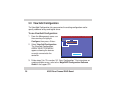
1
E1369
Zero-Channel RAID Board
(AZCRB)
Installation Guide
First Edition V1
August 2003
No part of this documentation, including the products and software described in it, may be reproduced, transmitted, transcribed,
stored in a retrieval system, or translated into any language in any form or by any means, except documentation kept by the
purchaser for backup purposes, without the express written permission of ASUSTeK COMPUTER INC. (“ASUS”).
ASUS PROVIDES THIS DOCUMENTATION “AS IS” WITHOUT WARRANTY OF ANY KIND, EITHER EXPRESS OR IMPLIED,
INCLUDING BUT NOT LIMITED TO THE IMPLIED WARRANTIES OR CONDITIONS OF MERCHANTABILITY OR FITNESS
FOR A PARTICULAR PURPOSE. IN NO EVENT SHALL ASUS, ITS DIRECTORS, OFFICERS, EMPLOYEES OR AGENTS BE
LIABLE FOR ANY INDIRECT, SPECIAL, INCIDENTAL, OR CONSEQUENTIAL DAMAGES (INCLUDING DAMAGES FOR
LOSS OF PROFITS, LOSS OF BUSINESS, LOSS OF USE OR DATA, INTERRUPTION OF BUSINESS AND THE LIKE), EVEN
IF ASUS HAS BEEN ADVISED OF THE POSSIBILITY OF SUCH DAMAGES ARISING FROM ANY DEFECT OR ERROR IN
THIS DOCUMENTATION OR PRODUCT.
Product warranty or service will not be extended if: (1) the product is repaired, modified or altered, unless such repair, modification
of alteration is authorized in writing by ASUS; or (2) the serial number of the product is defaced or missing.
Products and corporate names appearing in this documentation may or may not be registered trademarks or copyrights of their
respective companies, and are used only for identification or explanation and to the owners’ benefit, without intent to infringe.
For documentation updates, visit the ASUS website at www.asus.com.tw.
The specifications and information contained in this documentation are furnished for informational use only, and are subject to
change at any time without notice, and should not be construed as a commitment by ASUS. ASUS assumes no responsibility or
liability for any errors or inaccuracies that may appear in this documentation, including the products and the software described
in it.
Copyright © 2003 ASUSTeK COMPUTER INC. All Rights Reserved.
2
ASUS Zero-Channel RAID Board
Contents
Conventions ............................................................................................ 4
Symbols ............................................................................................ 4
Typography ....................................................................................... 4
Welcome! ................................................................................................ 5
1. Package contents ............................................................................. 5
2. Features ........................................................................................... 6
3. Board layout ..................................................................................... 8
4. Board installation .............................................................................. 9
5. RAID configuration ......................................................................... 13
5.1
5.2
5.3
5.3
Configuring arrays and logical drives .................................... 15
Easy Configuration ................................................................ 16
New Configuration ................................................................. 25
View/Add Configuration ......................................................... 28
ASUS Contact Information .................................................................... 32
ASUS Zero-Channel RAID Board
3
Conventions
Symbols
NOTE
Tips and additional information.
CAUTION Information to prevent damage to the components.
Typography
4
<Enter>
Indicates a keyboard key to press
<Ctrl><M>
Indicates a key combination to press simultaneously or consecutively
text input
Indicates text or command that you have to type on the screen
ASUS Zero-Channel RAID Board
Welcome!
Thank you for buying the ASUS Zero-Channel RAID board (AZCRB)! Now, you can
create and manage multiple disk arrays within your ASUS AP1600R 1U system with
PR-DSLR533 motherboard. With the convenient online management and configuration
utilities bundled, creating a RAID system has never been easier.
1. Package contents
Check the following items in your ASUS Zero-Channel RAID board package. Contact
your retailer if any item is damaged or missing.
ASUS Zero-Channel RAID Board
Screws ans standoffs
Support CD
Installation guide
If any of the items is damaged or missing, contact your dealer immediately.
ASUS Zero-Channel RAID Board
5
2. Features
The AZCRB is a proprietary daughterboard for the RAID connectors on the ASUS
PR-DLSR533 motherboard. The AZCRB includes the Intel® GC80303 integrated I/O
processor and 64MB ECC SDRAM cache, and 64MB ECC SDRAM.
RAID features
•
RAID levels 0/1/5 support
•
Background initialization for Quick RAID 5 setup
•
40 logical drives per controller
•
Auto-resume during array rebuild or reconstruction if the system shuts down
•
Variable stripe size for all logical drives
•
Supports multiple caching policies
- Write-back/Write-through
- Read Ahead: disable/enable/adaptive
- Cached direct I/O
6
ASUS Zero-Channel RAID Board
Fault tolerance
•
COD (Configuration on Disk) and NVRAM
•
Auto-detection of failed drives
•
Automatic and transparent rebuild of hot spare drives
•
Hot-swapping of drives without shutting the system down
•
SAF-TE enclosure management support
•
SMART support
Utilities
•
Power Console Plus for Windows® NT®/2000/XP/203
•
MegaManager
•
WebBIOS™
ASUS Zero-Channel RAID Board
7
3. Board layout
The two connectors underneath the board fit the RAID connectors on the PRDLSR533 motherboard.
AZCRB
RAID connectors
PR-DLSR533
®
PR-DLSR533 AZCRB Connectors
Standoff
Make sure that your system motherboard is PR-DLSR533. Only the
proprietary RAID connectors on this motherboard will support the AZCRB.
8
ASUS Zero-Channel RAID Board
4. Board installation
Before handling the board, touch a bare metal portion of the system to
discharge static electricity from your body. Wear a wrist strap grounded to the
system chassis when handling the board.
To install the board:
1. Make sure that the system is off.
PCI Riser Card and Bracket Assembly
2. Remove the system cover to access
the RAID connectors on the
motherboard. Refer to the AP1600R
system manual for instructions.
3. Remove the PCI riser card and
bracket assembly by pulling up the
metal lever to release and detach
the assembly from the chassis.
Metal Lever
ASUS Zero-Channel RAID Board
9
4. Locate the proprietary RAID
connectors on the motherboard.
5. Remove the board from its antistatic packaging.
RAID connectors on the motherboard
10
ASUS Zero-Channel RAID Board
6. Position the board as shown, then
plug the RAID connectors to the
corresponding connectors on the
motherboard.
The two holes (with standoffs) on
the board should also align with the
holes beside the RAID connectors
on the motherboard.
7. Use a Phillips screwdriver to secure
the board with two screws through
the holes.
ASUS Zero-Channel RAID Board
11
8. When the board is secure, replace
the riser card assembly into the
chassis.
9. Replace the chassis cover.
Install the hard disks following the instructions on your system manual.
12
ASUS Zero-Channel RAID Board
5. RAID configuration
The MegaRAID BIOS on your AZCRB board includes the MegaRAID Configuration
Utillity. Use this utility to create and configure disk arrays and logical drives.
The MegaRAID Configuration Utility is independent of the operating system so you
have to start the utility during the Power-On Self-Tests (POST), prior to entering the
operating system.
To start the MegaRAID Configuration Utility:
Turn on the system. During POST, hold the <Ctrl> and press <M> when the following
message appears:
Press <Ctrl><M> to run MegaRAID BIOS Configuration Utility
The MegaRAID BIOS Configuration Utility menu appears. See the menu image on
the next page.
If you do not press <Ctrl><M> within a few seconds after the message, the
system continues with the normal boot procedure.
ASUS Zero-Channel RAID Board
13
The initial menu of the MegaRAID BIOS Configuration Utility shows the Management
menu. Each option in the menu leads to different sub-menus that allow you to create
and configure RAID drives.
Management menu options
Configure
Select to configure physical arrays and logical
drives.
Initialize
Select to initialize one or more logical drives.
MegaRAID BIOS Config Utility(40-Ld) Ver5.40 Apr 21, 2003 Standard:Adapter-01
Management
Configure
Initialize
Objects
Format
Rebuild
Check Consistency
Objects
Select to access controllers, logical drives,
and physical drives individually.
Format
Select to format hard disk drives.
Configure Logical Drive(s)
Use cursor keys to navigate between items and Press ENTER to select an option
Rebuild
Select to rebuild failed hard disk drives.
Check Consistency
Select to verify the correctness of the redundancy data in logical drives configured as RAID
level 0, 1, or 5.
14
ASUS Zero-Channel RAID Board
5.1 Configuring arrays and logical drives
Depending on your current drive configuration or number of existing drives, you may
create physical arrays and logical drives using either one of the following methods:
•
•
•
Easy Configuration
New Configuration
View/Add Configuration
General procedure for configuring arrays and logical drives
1. Select a configuration method.
2. Designate hot spares (optional).
3. Create arrays using the available
physical drives.
4. Define logical drive(s) using the
space in the arrays.
5. Save the configuration information.
6. Initialize the new logical drives.
The procedure for each configuration method varies on the level of user input.
The succeeding sections give specific instructions on the method that you
wish to use. Refer to the MegaRAID Configuration Software Guide in the
support CD for detailed information.
ASUS Zero-Channel RAID Board
15
5.2 Easy Configuration
The Easy Configuration method allows you to create a basic logical drive
configuration where every physical array you define is automatically associated with
one logical drive.
If you have an existing logical drive configuration, using this method does not erase
the current configuration information.
This method allows you to change the RAID level, stripe size, write policy, read
policy, and cache policy parameters.
MegaRAID BIOS Config Utility(40-Ld) Ver5.40 Apr 21, 2003 Standard:Adapter-01
To use Easy Configuration:
1. From the Management menu, use
the arrow keys to highlight
Configure, then press <Enter>.
Configure
Management Easy Configuration
New Configuration
Configure
View/Add Configuration
Initialize
Clear Configuration
Objects
Specify
Bootable
Logical Drive
Format
Rebuild
Check Consistency
2. Select Easy Configuration, then
press <Enter>.
Defines Physical Arrays. An array will automatically become a logical drive
Use cursor keys to navigate between items and Press ENTER to select an option
16
ASUS Zero-Channel RAID Board
The Easy Configuration-ARRAY
SELECTION MENU appears. Use
the command bar hot keys to
perform the configuration functions.
MegaRAID BIOS Config Utility(40-Ld) Ver5.40 Apr 21, 2003 Standard:Adapter-01
Easy Configuration - ARRAY SELECTION MENU
Channel-1
Management
ID
Configure
0 READY
Initialize
Objects
1 READY
Format
Rebuild
Check Consistency 2 READY
3
Press:
<F2> to display the manufacturer
data and error count for the
selected drive
<F3> to display the logical drives
that have been configured
Channel-2
ID
0
1
2
3
READY
4
4
5
5
6
6
Ch-1 ID-0 DISK
17521MB
FUJITSU MAN3184MC
0109
SPACE-Array,ENTER-Configure,F2-Drive Information,F3-Logical Drives,F4-HotSpare
Command bar hot keys
<F4> to designate the selected
drive as a hot spare
The command bar hot keys change depending on the active configuration
window.
ASUS Zero-Channel RAID Board
17
3. Use the arrow keys to select a
specific physical drive, then press
the <Space bar> to associate the
selected drive with the current array.
The indicator for the selected drive
changes from READY to ONLIN
Axx-xx.
>> where Axx-xx means:
A[array number]-[drive number]
MegaRAID BIOS Config Utility(40-Ld) Ver5.40 Apr 21, 2003 Standard:Adapter-01
Easy Configuration - ARRAY SELECTION MENU
Channel-1
Management
ID
Configure
0 ONLIN A01-01
Initialize
Objects
1 ONLIN A01-02
Format
Rebuild
Check Consistency 2 ONLIN A01-03
3
ONLIN A01-04
Channel-2
ID
0
1
2
3
4
4
5
5
6
6
Ch-1 ID-0 DISK
17521MB
FUJITSU MAN3184MC
0109
SPACE-Array,ENTER-Configure,F2-Drive Information,F3-Logical Drives,F4-HotSpare
For example, ONLIN A01-01 means
disk drive 1 in array 1.
If possible, use identical drives (with the same type and capacity) in one array.
If you use drives of different capacities in one array, all the drives are treated
as if they have the capacity of the smallest drive in the array.
18
ASUS Zero-Channel RAID Board
The number of physical drives in an array determines the RAID levels that can be
implemented with the array.
RAID 0 requires one or more physical drives
RAID 1 requires exactly two physical drives
RAID 3 requires at least three physical drives
RAID 5 requires at least three physical drives
The ASUS AP1600R system with PR-DLSR533 motherboard supports four (4)
hard disk drives (HDDs) that may be configured to RAID 0 or RAID 5 using
the AZCRB. If you wish to configure more HDDs into multiple physical arrays
(spanning of arrays), you may opt to connect a storage system to the
AP1600R. Refer to the MegaRAID Configuration Software Guide in the
support CD for detailed information on this feature.
ASUS Zero-Channel RAID Board
19
4. When finished creating the array,
press <Enter> to start the
configuration. The Logical Drive
Configured screen appears
showing the logical drive being
configured and the existing logical
drives, if any.
5. Set the RAID level for the logical
drive. Highlight RAID then press
<Enter> to display the available
RAID levels.
Logical Drive Configured
LD
1
RAID
5
Size #Stripes
52563MB
4
Logical Drive 1
RAID = 5
Size = 52563MB
Advanced Menu
Accept
6. Select your desired RAID level,
e.g. RAID 5, and press <Enter> to
confirm.
20
ASUS Zero-Channel RAID Board
StrpSz
64KB
Drive-State
OPTIMAL
RAID Level
RAID = 0
RAID = 5
7. Select the Advanced Menu to set the stripe size, write policy, read policy, and
cache policy.
Logical Drive 1
RAID = 5
Size = 52563MB
Advanced Menu
Accept
Cache Policy
Advanced
Cache IO
StripeSize = 64MB
Direct IO
Write Policy = WRTHRU
Read Policy = NORMAL
Cache Policy = Direct I/O
Stripe Size - specifies the size of the segments written to each disk in an array. You
can set the stripe size to either 2KB, 4KB, 8KB, 16KB, 32KB, 64KB, or 128KB. A
larger stripe size allows better performance when your system does sequential reads
often. Other set to a smaller stripe size.
Write Policy - sets the caching method. In Write-back method, the controller sends
a data transfer completion signal to the host when the controller cache has received
all the data in a transaction. In Write-through, the controller sends a data transfer
completion signal to the host when the disk subsystem has received all the data in a
transaction. Write-through allows more data security than Write-back, but the latter
allows better performance.
ASUS Zero-Channel RAID Board
21
Read Policy - enables the SCSI read-ahead feature for the logical drive. The
configuration options are Normal, Read-ahead, or Adaptive. In Normal setting, the
controller does not use read-ahead for the current logical drive. In Read-ahead, the
controller uses read-ahead for the current logical drive. In Adaptive setting, the
controller begins using read-ahead fi the two most recent disk accesses occurred in
sequential sectors. If all the requests are random, the algorithm reverts to Normal,
but succeeding requests are still evaluated for possible sequential operation.
Cache Policy - applies to reads on a specific logical drive, and does not affect the
read-ahead cache. Cache I/O specifies that all reads are buffered in the cache
memory. Direct I/O specifies that reads are not buffered in the cache memory. Data
is transferred concurrently to cache and host. Direct I/O does not override the cache
policy settings.
22
ASUS Zero-Channel RAID Board
8. When finished defining the current logical drive, select
Accept then press <Enter>.
9. If you have remaining unconfigured disk drives, the
array selection menu re-appears. Configure the drives
following steps 3 to 8.
10. When done, press <Esc> to exit
Easy Configuration. A screen
appears with a list of the configured
logical drive(s).
Logical Drive 1
RAID = 5
Size = 52563MB
Advanced Menu
Accept
MegaRAID BIOS Config Utility(40-Ld) Ver5.40 Apr 21, 2003 Standard:Adapter-01
Logical Drives Configured
Management
Configure
Initialize
Objects
Format
Rebuild
Logical
Drives
Check
Consistency
Logical Drive 1
LD
1
RAID
5
Size #Stripes
52563MB
4
StrpSz
64KB
Drive-State
OPTIMAL
Select Logical Drive
SPACE-(De)Select, F2-(De)Select All Drives, F10-Initialize
ASUS Zero-Channel RAID Board
23
Before doing the next steps, make sure that you do not have data in the hard
disk drives that you wish to keep. Initializing erases all data stored in the
drives!
11. From the Management menu, use
the arrow keys to highlight
Initialize, then press <Enter>.
12. When prompted, select YES to start
initialing the logical drive(s) that you
have configured.
MegaRAID BIOS Config Utility(40-Ld) Ver5.40 Apr 21, 2003 Standard:Adapter-01
Logical Drives Configured
Management
Configure
Initialize
Objects
Format
Rebuild
Logical
Drives
Check
Consistency
Logical Drive 1
LD
1
RAID
5
Size #Stripes
52563MB
4
StrpSz
64KB
Drive-State
OPTIMAL
Initialize?
YES
NO
Initialize Will Destroy Data on Selected Logical Drive(s)
ENTER-Select
24
ASUS Zero-Channel RAID Board
5.3 New Configuration
The New Configuration method allows you to discard the existing configuration
information, and configure a new array and logical drives. This method lets you
change the RAID level, stripe size, write policy, read policy, and cache policy
parameters, and associate logical drives with multiple or partial arrays.
Choosing New Configuration erases the existing configuration information on
the selected controller. If you want to keep the current configuration and add
other drives to the array, select View/Add Configuration. See page 28.
To use New Configuration:
1. From the Management menu, use
the arrow keys to highlight
Configure, then press <Enter>.
2. Select New Configuration. The
New Configuration-ARRAY
SELECTION MENU appears
showing the devices currently
connected to the controller.
MegaRAID BIOS Config Utility(40-Ld) Ver5.40 Apr 21, 2003 Standard:Adapter-01
Configure
Management Easy Configuration
New Configuration
Configure
View/Add Configuration
Initialize
Clear Configuration
Objects
Specify
Bootable
Logical Drive
Format
Rebuild
Check Consistency
Erases Configuration
Use cursor keys to navigate between items and Press ENTER to select an option
ASUS Zero-Channel RAID Board
25
The New Configuration-ARRAY
SELECTION MENU appears. Use
the command bar hot keys to
perform the configuration functions.
MegaRAID BIOS Config Utility(40-Ld) Ver5.40 Apr 21, 2003 Standard:Adapter-01
New Configuration - ARRAY SELECTION MENU
Channel-1
Management
ID
Configure
0 READY
Initialize
Objects
1 READY
Format
Rebuild
Check Consistency 2 READY
3
Press:
<F2> to display the manufacturer
data and error count for the
selected drive
Channel-2
ID
0
1
2
3
READY
4
4
5
5
6
6
Ch-1 ID-0 DISK
17521MB
FUJITSU MAN3184MC
0109
SPACE-Array,ENTER-Configure,F2-Drive Information,F3-Logical Drives,F4-HotSpare
<F3> to display the logical drives
that have been configured
<F4> to designate the selected
drive as a hot spare
<F10> to display the logical drive
configuration screen
The command bar hot keys change depending on the active configuration
window.
26
ASUS Zero-Channel RAID Board
3. Use the arrow keys to select a
specific physical drive, then press
the <Space bar> to associate the
selected drive with the current array.
The indicator for the selected drive
changes from READY to ONLIN
Axx-xx.
>> where Axx-xx means:
A[array number]-[drive number]
MegaRAID BIOS Config Utility(40-Ld) Ver5.40 Apr 21, 2003 Standard:Adapter-01
New Configuration - ARRAY SELECTION MENU
Channel-1
Management
ID
Configure
0 ONLIN A01-01
Initialize
Objects
1 ONLIN A01-02
Format
Rebuild
Check Consistency 2 ONLIN A01-03
3
ONLIN A01-04
Channel-2
ID
0
1
2
3
4
4
5
5
6
6
Ch-1 ID-0 DISK
17521MB
FUJITSU MAN3184MC
0109
SPACE-Array,ENTER-Configure,F2-Drive Information,F3-Logical Drives,F4-HotSpare
For example, ONLIN A01-01 means
disk drive 1 in array 1.
If possible, use identical drives (with the same type and capacity) in one array.
If you use drives of different capacities in one array, all the drives are treated
as if they have the capacity of the smallest drive in the array.
4. Follow steps 4 to 12 in section “5.2 Easy Configuration.” For instructions on
creating multiple arrays, refer to the MegaRAID Configuration Software
Guide in the support CD.
ASUS Zero-Channel RAID Board
27
5.3 View/Add Configuration
The View/Add Configuration lets you examine the existing configuration and/or
specify additional arrays and logical drives.
To use View/Add Configuration:
1. From the Management menu, use
the arrow keys to highlight
Configure, then press <Enter>.
2. Select View/Add Configuration.
The View/Add ConfigurationARRAY SELECTION MENU
appears showing the devices
currently connected to the
controller.
MegaRAID BIOS Config Utility(40-Ld) Ver5.40 Apr 21, 2003 Standard:Adapter-01
Configure
Management Easy Configuration
New Configuration
Configure
View/Add Configuration
Initialize
Clear Configuration
Objects
Specify Bootable Logical Drive
Format
Rebuild
Check Consistency
Use cursor keys to navigate between items and Press ENTER to select an option
3. Follow steps 3 to 12 in section “5.2 Easy Configuration.” For instructions on
creating multiple arrays, refer to the MegaRAID Configuration Software
Guide in the support CD.
28
ASUS Zero-Channel RAID Board
NOTES
ASUS Zero-Channel RAID Board
29
NOTES
30
ASUS Zero-Channel RAID Board
NOTES
ASUS Zero-Channel RAID Board
31
ASUS Contact Information
ASUSTeK COMPUTER INC. (Asia-Pacific)
Marketing
Address:
150 Li-Te Road
Peitou, Taipei, Taiwan 112
General Tel.: +886-2-2894-3447
General Fax: +886-2-2894-3449
Web Site:
www.asus.com.tw
ASUS COMPUTER INTERNATIONAL (America)
Marketing
Address:
44370 Nobel Drive, Fremont,
CA 94538, USA
General Fax: +1-502-933-8713
General Email: [email protected]
ASUS COMPUTER GmbH (Germany and Austria)
Marketing
Address:
Harkortstr. 25 D-40880 Ratingen,
BRD, Germany
General Fax: +49-2102-9599-31
General Email: [email protected]
(for marketing requests only)
Technical Support
MB/Others (Tel):
Notebook (Tel):
Desktop/Server (Tel):
Support Fax:
+886-2-2890-7121 (English)
+886-2-2890-7122 (English)
+886-2-2890-7123 (English)
+886-2-2890-7698
Technical Support
Support Fax:
General Support:
Web Site:
Support E-mail:
+1-502-933-8713
+1-502-995-0883
usa.asus.com
[email protected]
Technical Support
Support Hotline:
Support Fax:
Support (Email):
Web Site:
15-061095000
32
+49-2102-95990 (Components)
+49-2102-959910 (Notebook PC)
+49-2102-959911
www.asuscom.de/support
(for online support)
www.asuscom.de
ASUS Zero-Channel RAID Board