1
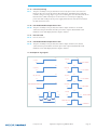
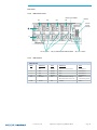
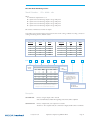
DESIGN GUIDE DESIGN GUIDE Table of Contents Overview of Product............................................................................................................................ 1 Standard Features................................................................................................................................ 1 Optional Features................................................................................................................................ 1 Mechanical Considerations................................................................................................................. 2 MicroPAC Do’s and Don’ts................................................................................................................... 2 Terms and Acronyms............................................................................................................................ 2 Brief Technical Description.................................................................................................................. 3 Output Power De-rating Curve.......................................................................................................... 4 MicroPAC to MIcroPAC Current Sharing............................................................................................ 4 MicroPAC Power Shed Mode.............................................................................................................. 5 1.1.1 Introduction to the MicroPAC Power Shed Mode..................................................................... 5 1.1.2 Power Shed Mode Prerequisites............................................................................................... 5 1.1.3 Configuring Power Shed Mode................................................................................................ 5 1.1.4 Power Shedding Bands............................................................................................................. 5 1.1.5 Power Shed Mode Functional Description................................................................................ 6 1.1.6 Shoot First, Ask Questions Later............................................................................................... 7 1.1.7 No Load Power Dissipation with and without Power Shed Mode.............................................. 7 Customer Interface Connector Kit (19-130066)................................................................................. 8 Field Replacement Unit....................................................................................................................... 8 Field Replacement Unit Instructions.................................................................................................. 9 Customer Interface............................................................................................................................ 10 1.1.8 Input Power Connector Pin Designation (AC Use Only)........................................................... 10 1.1.9 Input Power Connector Pin Designation (DC Use Only)........................................................... 10 1.1.10 Customer Interface Pin Designation........................................................................................ 10 DESIGN GUIDE Table of Contents (Cont.) J2 Customer Interface Signals........................................................................................................... 11 1.1.11 Auxiliary Supply...................................................................................................................... 11 1.1.12 ED/1 Enable/Disable Output Channel One.............................................................................. 11 1.1.13 Over Temperature Warning (Non Latching)............................................................................. 11 1.1.14 Over Temperature Shutdown (latching).................................................................................. 11 1.1.15 ED/3 Enable/Disable Output Channel Three............................................................................ 11 1.1.16Power.................................................................................................................................... 11 1.1.17 Standby Mode........................................................................................................................ 11 1.1.18 General Shut Down (GSD)...................................................................................................... 11 1.1.19 Fan Fault (Latching)................................................................................................................ 12 1.1.20 ED/2 Enable/Disable Output Channel Two.............................................................................. 12 1.1.21 Not Connected....................................................................................................................... 12 1.1.22 ED/4 Enable/Disable Output Channel Four.............................................................................. 12 1.1.23 Output TTL Logic Signals........................................................................................................ 12 Mechanical......................................................................................................................................... 13 1.1.24 Physical Dimensions/Markings................................................................................................ 13 1.1.25 Physical Weight...................................................................................................................... 13 Front Panel......................................................................................................................................... 14 1.1.26 LED Indicator Panel................................................................................................................. 14 1.1.27 LED Function.......................................................................................................................... 14 MicroPAC Model Numbering Scheme.............................................................................................. 15 Specifications..................................................................................................................................... 16 Overview of Product The MicroPAC is a factory configurable power supply providing up to 1,300 W of continuous power in a small slimline 1u package. The power supply provides up to 4 isolated outputs and combines power factor correction along with high efficiency and power density. The MicroPAC boasts a power density of 25Win3 and efficiency up to 92%, the power supply is available in a wide temperature range configuration and for harsh environments and mil-cots applications conformal coated. All configurations carry full safety agency approvals i.E. Ul60950 en60950 and are CE marked. The MicroPAC power supply platform supports a wide range of customer power requirements and is especially suited for distributed power architectures. The design offers a small flexible cost-effective solution for applications requiring high efficiency and power density. The isolated outputs may be placed in parallel/series configurations with automatic current sharing. For applications requiring higher power levels the MicroPAC's can be configured in arrays with box to box current sharing. Applications > > > > > > > > Factorized power architectures Distributed bus architectures Industrial Automation equipment Printing MIL-COTS applications Telecommunications Renewable energy Standard Features > High efficiency up to 92% > Small Size > High power density (25W/In3) > Up to 1,300 W (configuration dependent) > Low power standby mode (Green mode) > Universal Input (85 – 264 Vac) (47 – 400 Hz) > DC Input (120 – 300 Vdc) > Up to 4 Isolated outputs > 12 V output standard > 48 V output standard > Aux isolated 5 V @ > Individual output > > > > > > > > > > 500 mA bias standby supply Output parallel capability Output series capability Output current sharing MicroPAC to MicroPAC current sharing Power shed capability Vibration MIL-STD 810-F figure 514.5C-17 Over temperature warning Over temperature shutdown Intelligent Fan control Field replaceable Fan > > > > enable / disable All output enables / disable capability TTL control signals Visual LED display panel Shock MIL-STD 810F Method 516.5 procedure 1, terminal peak saw-tooth wave, 40G 11 mS Optional Features > Extended temperature range -40ºC to +55ºC operation > Conformal coated > Power shed Mode vicorpower.com Applications Engineering: 800 927.9474 Page 1 Mechanical Considerations The MicroPAC power supply can be mounted on four of the six surfaces using standard 6-32 screws with a maximum torque of 7 inch-lb. When using the mounting points the maximum insertion depth of the screw into the chassis from the outside surface must not exceed 0.125”. When considering a mounting location and/or orientation it is important not to restrict the air flow entering and exiting the MicroPAC. Air is drawn into the MicroPAC through the fan guard located next to the input power connector at the rear of the power supply and exhausts through the load side of the power supply next to the LED display panel. Westcor recommends a minimum clearance of 2” be kept at the front and rear of the MicroPAC. Care should be taken to minimize the output cabling as not impede the air exhausting from the MicroPAC, the output screw securing the cabling to the output terminals should be torque to 15 inc-lb not to exceed 20 inc-lb. MicroPAC Do’s and Don’ts > Do not operate the without a secure protective earth (PE) lead connected to the input power connector. Do not operate the MicroPAC with AC input without inserting a correctly rated Vac fuse. Do not operate the MicroPAC with DC input without inserting a correctly rated Vdc fuse. Do not obstruct the fan air intake or air exhaust. (Care should be taken when connecting cabling). Do not connect or disconnect the output +Out or –Out cabling while the MicroPAC is in operation. Always make sure the output screws are properly torqued [15 inch-lb] before applying power. Run the output +Out and –Out cabling together preferably in a twisted pair configuration from the MicroPAC to the load. > Do not attempt to repair or modify the MicroPAC power supply. > Use correctly rated wire size for both input and output to avoid overheating and excessive voltage drop. > > > > > > Terms and Acronyms The following terms and acronyms are used throughout this document. Acronym Term AMLApproved Manufacturing List Acronym VAC Volts Alternating Current VDC Volts Direct Current FPA Factorized Power Architecture FRU GSD Field Replaceable Unit General shutdown MTBF Mean Time Between Failure NTC Negative Temperature Coefficient BCM Bus Converter Module PE LED Protective Earth Light Emitting Diode vicorpower.com Term EMIElectro-Magnetic Interference Acronym PFC Term Power Factor Correction PCB Printed Circuit Board PS Power Supply PSM Power Shed Mode PC Performance Criteria RoHSRestriction of Hazardous Substances Applications Engineering: 800 927.9474 Page 2 vicorpower.com PE AC PE +5 V +12 V Smart Fan controller FAN EMI Filter DC 85 – 264 Vrms 47 – 400 Hz 120 – 300 Vdc External 15 A fuse required MicroPAC Chassis PIC program Port T Temp detecon on Boost heatsink Bridge Recfier PE Microcontroller PFC Control +12 V Boost Converters 20 MHz +5 V +12 V BCM control So Start +5 V +12 V House Keeping BCM_1 BCM_1 BCM_1 BCM_1 Applications Engineering: 800 927.9474 Over Temp Fan Fault AC_OK Standby Mode GSD ED/4 ED/3 ED/2 ED/1 Reverse logic 1) +5.0 Vdc 2) OV 3) ED 1 4) Over Temp Warning 5) ED 3 6) AC_OK 7) Standby Mode 8) General Shutdown 9) Fan Fault 10) ED 2 11) N/C 12) ED 4 Interface Connector LED Indicators Isolated +5 Vdc / 500 mA Isolated Output Isolated Output Isolated Output Isolated Output Brief Technical Description The MicroPAC power supply is designed to operate using a single phase voltage source input between 85 Vrms and 264 Vrms or 120 to 300 V dc source. The basic building blocks of the MicroPAC are an EMI filter, Power Factor Correction stage, cooling fan, and housekeeping, associated microcontroller circuits along with customer interfaces and galvanic isolated outputs and control signals. Figure 1: Simple Block Diagram Page 3 Output Power De-rating Curve The MicroPAC is designed to operate from a single electrical phase; as such it can be operated directly from a normal wall outlet socket. These sockets are normally rated for 12 A continuous current draw and 15 A peak current draw. With this in mind it is necessary to institute a power de-rating curve to maintain the operational range of the MicroPAC within these boundaries. Figure 2: Output Power De-rating Curve vs. AC Input Voltage Output Power De-rating Curve vs. AC Input voltage Output Power (W) 1300 1255 1210 1165 1120 1075 1030 985 940 Output Power (Watts) 895 850 80 90 100 110 120 130 140 150 160 170 180 190 200 210 220 230 AC Input (Vrms) MicroPAC to MicroPAC Current Sharing The MicroPAC power supplys with the same output voltages can be placed in parallel arrays by connecting the output positive (+) and return (-) rails to the respective positive and return rails of the next MicroPAC. If individual MicroPAC's are configured in an array it is necessary to make sure all MicroPAC are powered up at the same time. Pin 2 (0V +5V return) of the customer interface connector should be daisy chained together on each MicroPAC in the array. The GSD signal Pin 8 should also be daisy chained together and be used to turn on all outputs at the same time. The current sharing is achieved by using the droop sharing method and produces in the order of 5 –10% Current sharing accuracy. (Contact factory for details). It is important to note that following good cable routing and symmetry is critical for good current sharing and load balancing. vicorpower.com Applications Engineering: 800 927.9474 Page 4 MicroPAC Power Shed Mode 1.1.1 Introduction to the MicroPAC Power Shed Mode The aim of the power shed mode is to increase the overall light load efficiency of the MicroPAC. This is achieved by minimizing the power dissipation when light load or no load conditions are present on the MicroPAC output. The original concept of improving light load efficiency for VI Chip Bus Converter arrays was developed by Mr. Ankur Patel (Vicor Product Line Engineer). The following is an alternative method of power shedding incorporated within the MicroPAC. 1.1.2 Power Shed Mode Prerequisites > > > > > 1.1.3 Configuring Power Shed Mode Slots 1 to 4 must be populated All outputs must be the same voltage All slots must be configured in a parallel array Current rate slew rate not to exceed 20.8 A/s The PSM is not suitable for constant dynamic loads The Power Shed Mode is factory configured. 1.1.4 Power Shedding Bands There are four operational modes for the power shedding scheme. Category Customer Load Output 1 2 3 4 0.0 – 250 W 250 – 500 W 500 – 750 W 750 – 1200 W/1300 W Applications Engineering: 800 927.9474 vicorpower.com Output 1, active Output 1 and 2, active Output1, 2 and 3 active Output 1, 2, 3 and 4 active Page 5 1.1.5 Power Shed Mode Functional Description On power up with the power shed function enabled all four output channels are initially enabled, channel one to four LED’s should be illuminated. Circuitry internal to the MicroPAC monitors the amount of current drawn from the MicroPAC and is proportional to the customer load. If the load falls into category 1, the following will be observed. After 5 seconds output 4 will turn off, after 10 seconds output 3 will turn off, after 15 seconds output 2 will turn off. If the customer load falls into category 2, the following will be observed. After 5 seconds output 4 will turn off, after 10 seconds output 3 will turn off, output 1 and 2 will remain on. If the customer load falls into category 3, the following will be observed. After 5 seconds output 4 will turn off, output 1, 2 and 3 will remain on. If the customer load falls into category 4, all output will remain on. Figure 3: Power Shed Category 2 Category 1 On On Output 1 Output 1 Off Off On On Output 2 Output 2 Off On Off Off Off Off Off Off On Output 3 Output 3 Off On On Off Output 4 Output 4 Off Off 5 sec 5 sec 5 sec 5 sec 5 sec 10 sec 10 sec 15 sec Category 3 Category 4 On On Output 1 Output 1 Off On Off On Off On Output 2 Output 2 Off Output 3 On Output 3 Off On Off On Output 4 Output 4 Off Off Off 5 sec vicorpower.com Applications Engineering: 800 927.9474 Page 6 Shoot First, Ask Questions Later When the MicroPAC is operating in categories 1 to 3 and detects an increase in load current applied to the output which incurs into the next power band the internal microcontroller will turn all outputs on, regardless of the actual amount of load added. (Shoot first ask question later) with all the outputs enabled, the microcontroller will turn off redundant outputs In the Power Shed Mode this is a constant cycle of detecting output load and continually adjusting the outputs to satisfy that need. 1.1.7 No Load Power Dissipation with and without Power Shed Mode Power (Was) Figure 4: Plotted to the right is the average no load power dissipation when using four 12 V outputs. With the power shed enabled the average power dissipation is about 7.05 W; With the power shed disabled the power dissipation is around 28.20 W No Load Power Dissipaon @ 25C with 12 V Output 7.06 30 27.5 25 7.055 22.5 20 7.05 17.5 15 12.5 7.045 10 7.5 5 7.04 1 3 4 2 Number of BCM’s Power (Was) 1.1.6 Power (Was) Figure 5: Plotted to the right is the average no load power dissipation when using four 48 V outputs. With the power shed enabled the average power dissipation is about 8.25 W; With the power shed disabled the power dissipation is around 33 W. No Load Power Dissipaon @ 25C with 48 V Output 8.26 35 32 29 8.255 26 23 8.25 20 17 14 8.245 11 8 5 8.24 1 3 4 2 Number of BCM’s Power (Was) Power Shed Mode Disabled Power Shed Mode Enabled Power Shed Mode Disabled Power Shed Mode Enabled vicorpower.com Applications Engineering: 800 927.9474 Page 7 Customer Interface Connector Kit (19-130066) Material List Westcor Vendor Vendor # Item QTY Description Part Number Part Number 1 1 2 12 3 1 4 3 CONN HOUSING 12 POS MINITEK63-00168-12 FCI90311-012LF TERM FEM CRIMP 26-30 AWG63-00167-01FCI 77138-101LF CRIMP TOOL FOR ITEM 2----------------- FCI HT-151/RCY21151 CONN HOUSING 3 POS W/LATCH63-00084-03 MOLEX 39-01-4030 TERM FEM CRIMP 16 AWG63-00125-01 MOLEX 45750-3211 CRIMP TOOL FOR ITEM 4----------------- MOLEX 11-01-0199 Field Replacement Unit Field Replacement Unit Item QTY Description Westcor Part Number 10-130240-01 10-130241-01 1 2 1 1 ASSY FAN AVC DV-12M 40X28MM 14.4 CFM ASSY FAN SANYO DENKI -40C J-SPEED 40X28MM 18.4 CFM vicorpower.com Applications Engineering: 800 927.9474 Page 8 Field Replacement Unit Instructions. > Remove input power connector. > > > > > > > > > > > > > > > (this should never be attempted with the input power cable inserted) Remove output power connections Remove four screws, from the back panel (ref 1) two either side (ref; 2) Remove back panel (ref 1) Pull back the insulating material to gain access to the fan connector (ref 7) Depress the latching point on the fan connector (ref 7) The connector is polarized and removes vertically from the PCB housing Remove four screws (ref 4). The fan guard and fan are now free from the back panel. Insert new fan, making sure the arrow (ref 3) is pointed in the direction shown. (Towards the inside of the MicroPAC) Replace fan guard in the correct orientation (ref 5) Replace 4 screws (ref 4). The torque on these screw should be 5-6 inch-lb. (Friction tight) Insert fan connector (ref 7) into the fan housing. When inserted correctly you will not be able to remove without depressing the latch Fold the insulating material back Replace the back panel (ref 1) making sure the fan wire is routed to the side of the fan. Replace the four screws (ref 2). The torque on these screw is 5-6 inch-lb Never apply power to the MicroPAC until all of the reassembly is complete. Estimated replacement time 15 minutes Figure 5: Fan Assembly vicorpower.com Applications Engineering: 800 927.9474 Page 9 Customer Interface 1.1.8 Input Power Connector Pin Designation (AC Use Only) Pin 1.1.9 Designation 1Live (L1) 2Neutral (L2) 3Protective Earth (PE) Input Power Connector Pin Designation (DC Use Only) Pin Designation 1 + DC (L1) 2 - DC (L2) 3 Protective Earth (PE) 1.1.10 Customer Interface Pin Designation Pin Designation 1 2 3 4 5 6 7 8 9 10 11 12 +5V 0V (+5V RETURN) ED 1 Overtemperature warning /Overtemperature shutdown ED 3 AC-OK STANDBY MODE GENERAL SHUTDOWN FAN FAULT ED 2 N/C ED 4 vicorpower.com Applications Engineering: 800 927.9474 Page 10 J2 Customer Interface Signals All customer interface signals are referenced to the auxiliary +5V return (pin 2) 1.1.11 Auxiliary Supply Pin 1 An auxiliary +5V supply output is available Pin 2 with a maximum output of 500 mA (2.5 W). 0 V; this is the return for the above +5V. 1.1.12 ED/1 Enable/Disable Output Channel One Pin 3 ED/1: This pin is normally at +5V potential, this enables output channel one. To disable output one this pin should be shorted to pin 2. If the output is disabled LED 1 will illuminate on the LED display until the output is enabled. 1.1.13 Over Temperature Warning (Non Latching) Pin 4 This pin is normally at +5V potential when referenced to pin 2. At approximately 50°C ambient temperature the over temperature warning signal will be pulled low, the fault LED indicator will illuminate solid yellow. This is just a warning that you are approximately +5°C away from the maximum operating temperature of the MicroPAC. No other action by the power supply will be taken. 1.1.14 Over Temperature Shutdown (Latching) Pin 4 The same pin is used as the over temperature warning. At approximately +56°C the over temperature shutdown is triggered, the fault LED previously illuminated a solid yellow due to the over temperature warning will now begin to flash at approximately 2 Hz. All outputs will be disabled. The power supply will go into a shutdown mode; however the fan will be left running to cool the unit, the MicroPAC will remain in shutdown mode until the temperature reaches an acceptable level and the power is recycled. 1.1.15 ED/3 Enable/Disable Output Channel Three Pin 5 ED/3: This pin is normally at +5V potential, this enables output channel three. To disable channel three this pin should be shorted to pin 2. If the output is disabled LED 3 will illuminate on the LED display until the output is enabled. 1.1.16 Power Pin 6 If the AC or DC power input is present the pin is normally at +5V potential when referenced to pin 2. The blue power LED will illuminate. If the AC or DC input is lost pin 6 will fall to logic level zero and the blue power LED will turn off. This will allow a minimum 10 mS power loss warning to the customer. 1.1.17 Standby Mode Pin 7 This pin is normally at +5V potential when referenced to pin 2. If this pin is shorted to pin 2 the MicroPAC will enter a low power standby mode. In this mode all outputs will be disabled, the main PFC power supply will be shut-down along with the fan. The blue power LED will change to an amber color. When the short is removed the power power supply will return to normal operation and the power LED will turn to blue. 1.1.18 General Shut Down (GSD) Pin 8 This pin is normally at +5V potential when referenced to pin 2. If this pin is shorted to pin 2 all the channels will be disabled and all four of the GSD LED’s (1-4) will illuminate. vicorpower.com Applications Engineering: 800 927.9474 Page 11 1.1.19 Fan Fault (Latching) Pin 9 This pin is normally at +5V potential when referenced to pin 2. In the event of the fan failing the detection circuit will shut the MicroPAC down, and illuminate the fault LED red. Pin 9; will go from logic high to logic low level during this event. The MicroPAC will be latched in this condition until power is removed for 30 seconds, upon reapplying power if the fault is still persist the power supply will latch in the shut-down mode until the fault has been cleared. 1.1.20 Ed/2 Enable/Disable Output Channel Two Pin 10 This pin is normally at +5V potential, this enables output channel two. To disable channel two this pin should be shorted to pin 2. If the output is disabled LED 2 will illuminate on the LED display until the output is enabled 1.1.21 Not Connected Pin 11 Pin 11 is not u sed 1.1.22 Ed/4 Enable/Disable Output Channel Four Pin 12 This pin is normally at +5V potential, this enables output channel four. To disable channel four this pin should be shorted to pin 2. If the output is disabled LED 4 will illuminate on the LED display until the output is enabled 1.1.23 Output TTL logic Signals +5 V +5 V ED/ 1 ( Pin 3) +5 V ( Pin 1) 0V 0V 0 V ( Pin 2) BCM 1 DISABLED +5 V +5 V ED/ 2 ( Pin 10) AC_ OK ( Pin 6) 0V 0 V +5 V 0V BCM 2 DISABLED +5 V FAN_ FAULT ( Pin 9) ED/ 3 ( Pin 5) 0 V 0 V 0 V BCM 3 DISABLED +5 V +5 V ED/ 4 ( Pin 12) OVER TEMPERATURE WARNING ( Pin 4) 0 V 0 V 0 V BCM 4 DISABLED +5 V +5 V 0V 0V 250 mS 250 mS vicorpower.com 0V 0 V ALL BCM’S DISABLED 0 V STANDBY MODE +5 V 250 mS 250 mS 2 Hz Pulse GSD( Pin 8) +5 V STANDBY MODE ( Pin 7) 0 V Applications Engineering: 800 927.9474 Page 12 Applications Engineering: 800 927.9474 0 USE SCREW #6-32 . MAXIMUM INTRUSION OF SCREW INTO CHASSIS FROM OUTSIDE SURFACE OF CHASSIS = .125" USE CRIMP TOOL FROM MOLEX P/N - 11-01-0199 FOR J5 4. 3.2 . 4 2X CUSTOMER MOUNTING USE CRIMP TOOL FROM FCI P/N - HT-151 OR RCY21151 FOR J2 2 . WESTCOR MATING CONNECTORS KIT P/N 19-130066. INTERPRET DRAWING PER ANSI Y14.5-1994. 5.800 3.1 . 1. NOTES: UNLESS OTHERWISE SPECIFIED 0 .500 AIR FLOW 1.329 0 2X 1.329 2X 5.863 2X 6.486 7.38 7.44 7.45 CH-1 CH-2 CH-3 .312 2X 1.325 0 .287 .502 .644 vicorpower.com CH-4 A 3.542 4.00 3.688 0 3.502 3.356 .19 0 4X CUSTOMER MOUNTING 4 SEE DETAIL-A FOR PINOUT 4X CUSTOMER MOUNTING 4 4 J2 12 11 DETAIL A SCALE 8 : 1 8 10 6 5 7 4 3 0 0 0 1.000 2 , 3.1 2X .500 1.72 SEE NOTE - 9 2 1.329 1 2X CUSTOMER MOUNTING 4 A/C OKAY STANDBY MODE GENERAL SHUTDOWN FAN FAULT ENABLED/DISABLED - 2 NOT CONNECTED ENABLED/DISABLED - 4 6 7 8 9 10 11 12 ENABLED/DISABLED - 1 ENABLED/DISABLED - 3 5 0 VOLT OVER TEMPERATURE WARNING .500 3 3.2 CHASSIS GROUND NEUTRAL LIVE J5 CHASSIS GROUND 0 4 +5 VOLT 2 FUNCTION 1 PIN NUMBER OUTPUT POWER CONNECTOR USE SCREW SIZE #6-32 Mechanical 1.1.24 Physical Dimensions/Markings 1.1.25 Physical Weight 2.15Lbs Page 13 5.800 Front Panel 1.1.26 LED Indicator Panel PWR /AC_OK / STANDBY CH1 CH2 CH3 LED Panel CH4 Customer Interface Connector CH 1-4 DC_OK LED FAN_FLT /OVER TEMP/OVER TEMP SHUTDOWN GSD / CH 1 - 4 Disable 1.1.27 LED Function LED Function LED# Function 1 Color Function 2 Color 1 ED 1 OrangeGSD (General Shutdown) 2 ED 2 OrangeGSD 3 ED 3 OrangeGSD 4 ED 4 OrangeGSD FLT Fan Fault Red Overtemperature warning Overtemperature shut down Yellow/Green Yellow/Green Yellow/Green Yellow/Green Yellow 2 Hz Flashing Yellow PWR Amber AC-OK vicorpower.com Blue Standby Applications Engineering: 800 927.9474 Page 14 MicroPAC Model Numbering Scheme Model Number: UPa - bbbb - cde Where a = number of outputs from 1 to 4 b = equals a character denoting output 1 voltage and power b = equals a character denoting output 2 voltage and power b = equals a character denoting output 3 voltage and power b = equals a character denoting output 4 voltage and power One character will denote a null for an output c, d, e will be characters denoting box level options such as fan cooling, conduction cooling, convection cooling, interfacing scheme, and rohs status. Output Voltage and Voltage Table (bbbb) Character Vout A B C D E F UP a - Number of outputs, 1 to 4 Watts 12300 12 600 12 900 12 1200 24 600 24 1200 b b b Character G H I J K Z b c Output Configuration Cooling Fill in character from chart below for each output F =Fan L = -40°C Fan b= Vout Watts b= Vout Watts A 12 300 G 48 325 B 12 600 H 48 650 C 12 900 I 48 975 D 12 1200 J 48 1300 E 24 600 K 36 900 F 24 1200 M [a] [a] Z [b] [b] Vout Watts 48 48 48 48 36 Null 325 650 975 1300 900 Null d e Interface Customer Option Non-Safety Related S=Standard (TTL levels) Signaling and Control I=Digital Bus Signaling and Control [a] M defines a slot with an air block filler, no BCM board [b] Z indicates the slot is populated with a BCM board that is connected in series or parallel with the adjacent slot RoHS Compliant G =RoHS N =Non-RoHS Examples: UP1-FZZZ-FSG Denotes a single output of 24 V 1200 W with a standard fan, standard TTL signaling and control, RoHS compliant UP4-AAAA-LIN Denotes 4 output unit, each output is 12 V 300 W. The fan is a -40°C capable unit, the control bus is digital, and the unit is non-RoHS vicorpower.com Applications Engineering: 800 927.9474 Page 15 Specifications Input Input Voltage 85 – 264 Vac DC Rating: 120 Vdc – 300 Vdc (¼” x 1¼”)Cooper Bussmann, (5 x 20 mm)Littelfuse, ABC-15, 216 series, External Fuse rated 15 Arated 16 A Littelfuse, (¼” x 1¼”)Littelfuse, 505 series, 505 series, rated 16 A/500 Vdcrated 16 A/500 Vdc Frequency 47 ~ 400 Hz Inrush Current Efficiency 30 A Peak ≥92% @ Full load @ 25°C ambient 48 V output Power factor >0.95 typ. Meets EN61000-3-2 ≥91% @ Full load @ 25°C ambient 12 V output Turn-on time AC on 1.5 sec TYP Conducted EMI EN55022 Class B Information technology equipment — Radio disturbances characteristics — Limits and methods of measurement BS EN55022:1998; CISPR 22:1997, incorporating corrigendum Harmonic distortion Meets IEC 61000-3-2 Isolation Meets IEC 60950 Leakage current <3.5 mA @ 264 Vac @ 63 Hz Hold up time 20 mS typical Warranty 2 Years Output Number of outputs 1 to 4 Normal output voltages 12 V, 24 V, 36 V and 48 V (contact factory for details) Maximum output current 100 A @ 12 V Auxiliary output 5 V @ 0.5 A 50 mV p-p Voltage regulation 12 V output (11.3 V ~ 12.5 V) 48 V output (45 V ~ 50 V) Ripple and noise 12 V output (197 mV ~ 400 mV p-p) 48 V output (1.6 Vp-p) [27 A @ 48 V] (20 MHz bandwidth) Current sharing accuracy 5 to 10% Short circuit protection “Fold-Back” Technique Over voltage protection 12 V output set point 12.5 V typical Thermal protection All outputs disabled when internal temperature exceeds safe operating Maximum load 12 V up to 1200 W Maximum load 48 V up to 1300 W Maximum load 5.0 V Aux up to 2.5 W Maximum load capacitance 1000 µF per 12 V output vicorpower.com 48 V modules 50 V typical 100 µF per 48 V output Applications Engineering: 800 927.9474 Page 16 Specifications (Cont.) Environmental Storage temperature -40°C ~ +85°C Operating temperature -20°C ~ +55°C (Extended temperature range is available; -40°C to +55°C) Functional shock MIL-STD 810F Method 516.5 procedure 1, terminal peak saw-tooth wave, 40G 11 mS Vibration MIL-STD 810G for minimum integrity vibration Humidity 95% non condensing Cooling Fan cooled (field replaceable) temperature speed control Electromagnetic Compatibility EN61000-6-1n European General EMC Immunity IEC 61000-4-11 [50 Hz] Voltage Dips 30% for 0.5 prd, pc C Voltage Interrupts (pc C) IEC 61000-4-4 [TRANSIENT] EFT/Burst ± 1 kV AC leads ± 500 V DC leads. 5/50 nsec 5 kHz rep rate (pc B) IEC 61000-4-5 [SURGE] EN 61000-4-6 [0.15 to 80 MHz] Power line Surge AC in ± 2 kV CM ± 1 kV DM DC in ± 500 V CM & DM 1.2/μSec (pc B) RF Common Mode Input leads, AC & DC leads, CDN 150 kHz to 80 MHz, 3 Vrms with 80% AM @1 kHz (pa A) EN 61000-4-2 [ELECTROSTATIC] Electrostatic Discharge ± 4 kV Contact ± 8 kV Discharge (pc B) EN 61000-4-3 RF E-Field 80 MHz to 1 GHz 3 V/m with 80% AM @ 1 kHz (pc A) EN 61000-4-8 Power Freq H-Field 3A/M @ 50 Hz (pa A) Reliability FITTBD Service life 5 Years Safety & Regulatory UL UL 60950-1:2007 CAN C22.2 No. 60950-1-07 CSA CSA*60950 3rd Edition (CB Report to include all national deviations) EN EN 60950-1/A1:2010 IEC 60950-1-2005 2 Ed. +A1:2009 The Power Behind Performance vicorpower.com Applications Engineering: 800 927.9474 Page 17 Vicor’s comprehensive line of power solutions includes high density AC-DC and DC-DC modules and accessory components, fully configurable AC-DC and DC-DC power supplies, and complete custom power systems. Information furnished by Vicor is believed to be accurate and reliable. However, no responsibility is assumed by Vicor for its use. Vicor makes no representations or warranties with respect to the accuracy or completeness of the contents of this publication. Vicor reserves the right to make changes to any products, specifications, and product descriptions at any time without notice. Information published by Vicor has been checked and is believed to be accurate at the time it was printed; however, Vicor assumes no responsibility for inaccuracies. Testing and other quality controls are used to the extent Vicor deems necessary to support Vicor’s product warranty. Except where mandated by government requirements, testing of all parameters of each product is not necessarily performed. Specifications are subject to change without notice. Vicor’s Standard Terms and Conditions All sales are subject to Vicor’s Standard Terms and Conditions of Sale, which are available on Vicor’s webpage or upon request. Product Warranty In Vicor’s standard terms and conditions of sale, Vicor warrants that its products are free from non-conformity to its Standard Specifications (the “Express Limited Warranty”). This warranty is extended only to the original Buyer for the period expiring two (2) years after the date of shipment and is not transferable. UNLESS OTHERWISE EXPRESSLY STATED IN A WRITTEN SALES AGREEMENT SIGNED BY A DULY AUTHORIZED VICOR SIGNATORY, VICOR DISCLAIMS ALL REPRESENTATIONS, LIABILITIES, AND WARRANTIES OF ANY KIND (WHETHER ARISING BY IMPLICATION OR BY OPERATION OF LAW) WITH RESPECT TO THE PRODUCTS, INCLUDING, WITHOUT LIMITATION, ANY WARRANTIES OR REPRESENTATIONS AS TO MERCHANTABILITY, FITNESS FOR PARTICULAR PURPOSE, INFRINGEMENT OF ANY PATENT, COPYRIGHT, OR OTHER INTELLECTUAL PROPERTY RIGHT, OR ANY OTHER MATTER. This warranty does not extend to products subjected to misuse, accident, or improper application, maintenance, or storage. Vicor shall not be liable for collateral or consequential damage. Vicor disclaims any and all liability arising out of the application or use of any product or circuit and assumes no liability for applications assistance or buyer product design. Buyers are responsible for their products and applications using Vicor products and components. Prior to using or distributing any products that include Vicor components, buyers should provide adequate design, testing and operating safeguards. Vicor will repair or replace defective products in accordance with its own best judgment. For service under this warranty, the buyer must contact Vicor to obtain a Return Material Authorization (RMA) number and shipping instructions. Products returned without prior authorization will be returned to the buyer. The buyer will pay all charges incurred in returning the product to the factory. Vicor will pay all reshipment charges if the product was defective within the terms of this warranty. Life Support Policy VICOR’S PRODUCTS ARE NOT AUTHORIZED FOR USE AS CRITICAL COMPONENTS IN LIFE SUPPORT DEVICES OR SYSTEMS WITHOUT THE EXPRESS PRIOR WRITTEN APPROVAL OF THE CHIEF EXECUTIVE OFFICER AND GENERAL COUNSEL OF VICOR CORPORATION. As used herein, life support devices or systems are devices which (a) are intended for surgical implant into the body, or (b) support or sustain life and whose failure to perform when properly used in accordance with instructions for use provided in the labeling can be reasonably expected to result in a significant injury to the user. A critical component is any component in a life support device or system whose failure to perform can be reasonably expected to cause the failure of the life support device or system or to affect its safety or effectiveness. Per Vicor Terms and Conditions of Sale, the user of Vicor products and components in life support applications assumes all risks of such use and indemnifies Vicor against all liability and damages. Intellectual Property Notice Vicor and its subsidiaries own Intellectual Property (including issued U.S. and Foreign Patents and pending patent applications) relating to the products described in this data sheet. No license, whether express, implied, or arising by estoppel or otherwise, to any intellectual property rights is granted by this document. Interested parties should contact Vicor's Intellectual Property Department. Vicor Corporation 25 Frontage Road Andover, MA, USA 01810 Tel: 800-735-6200 Fax: 978-475-6715 Email Customer Service: [email protected] Technical Support: [email protected] Rev 1.0 7/12 vicorpower.com Applications Engineering: 800 927.9474 Page 18